EP0463399A2 - Sweep and vacuum xerographic cleaning method and apparatus - Google Patents
Sweep and vacuum xerographic cleaning method and apparatus Download PDFInfo
- Publication number
- EP0463399A2 EP0463399A2 EP91109011A EP91109011A EP0463399A2 EP 0463399 A2 EP0463399 A2 EP 0463399A2 EP 91109011 A EP91109011 A EP 91109011A EP 91109011 A EP91109011 A EP 91109011A EP 0463399 A2 EP0463399 A2 EP 0463399A2
- Authority
- EP
- European Patent Office
- Prior art keywords
- slit
- imaging surface
- toner
- cleaning
- housing
- Prior art date
- Legal status (The legal status is an assumption and is not a legal conclusion. Google has not performed a legal analysis and makes no representation as to the accuracy of the status listed.)
- Withdrawn
Links
Images

Classifications
-
- G—PHYSICS
- G03—PHOTOGRAPHY; CINEMATOGRAPHY; ANALOGOUS TECHNIQUES USING WAVES OTHER THAN OPTICAL WAVES; ELECTROGRAPHY; HOLOGRAPHY
- G03G—ELECTROGRAPHY; ELECTROPHOTOGRAPHY; MAGNETOGRAPHY
- G03G21/00—Arrangements not provided for by groups G03G13/00 - G03G19/00, e.g. cleaning, elimination of residual charge
- G03G21/0005—Arrangements not provided for by groups G03G13/00 - G03G19/00, e.g. cleaning, elimination of residual charge for removing solid developer or debris from the electrographic recording medium
- G03G21/0035—Arrangements not provided for by groups G03G13/00 - G03G19/00, e.g. cleaning, elimination of residual charge for removing solid developer or debris from the electrographic recording medium using a brush; Details of cleaning brushes, e.g. fibre density
-
- G—PHYSICS
- G03—PHOTOGRAPHY; CINEMATOGRAPHY; ANALOGOUS TECHNIQUES USING WAVES OTHER THAN OPTICAL WAVES; ELECTROGRAPHY; HOLOGRAPHY
- G03G—ELECTROGRAPHY; ELECTROPHOTOGRAPHY; MAGNETOGRAPHY
- G03G21/00—Arrangements not provided for by groups G03G13/00 - G03G19/00, e.g. cleaning, elimination of residual charge
- G03G21/0005—Arrangements not provided for by groups G03G13/00 - G03G19/00, e.g. cleaning, elimination of residual charge for removing solid developer or debris from the electrographic recording medium
- G03G21/0052—Arrangements not provided for by groups G03G13/00 - G03G19/00, e.g. cleaning, elimination of residual charge for removing solid developer or debris from the electrographic recording medium using an air flow; Details thereof, e.g. nozzle structure
-
- G—PHYSICS
- G03—PHOTOGRAPHY; CINEMATOGRAPHY; ANALOGOUS TECHNIQUES USING WAVES OTHER THAN OPTICAL WAVES; ELECTROGRAPHY; HOLOGRAPHY
- G03G—ELECTROGRAPHY; ELECTROPHOTOGRAPHY; MAGNETOGRAPHY
- G03G21/00—Arrangements not provided for by groups G03G13/00 - G03G19/00, e.g. cleaning, elimination of residual charge
- G03G21/0005—Arrangements not provided for by groups G03G13/00 - G03G19/00, e.g. cleaning, elimination of residual charge for removing solid developer or debris from the electrographic recording medium
- G03G21/007—Arrangement or disposition of parts of the cleaning unit
- G03G21/0076—Plural or sequential cleaning devices
-
- G—PHYSICS
- G03—PHOTOGRAPHY; CINEMATOGRAPHY; ANALOGOUS TECHNIQUES USING WAVES OTHER THAN OPTICAL WAVES; ELECTROGRAPHY; HOLOGRAPHY
- G03G—ELECTROGRAPHY; ELECTROPHOTOGRAPHY; MAGNETOGRAPHY
- G03G2221/00—Processes not provided for by group G03G2215/00, e.g. cleaning or residual charge elimination
- G03G2221/0005—Cleaning of residual toner
- G03G2221/001—Plural sequential cleaning devices
Definitions
- the present invention relates to an improved cleaning method and apparatus that collects residual toner from the photoconductive surface of an electrophotographic copying machine by using a vacuum slit and fiber-like bristles or open-cell foam padding.
- U. S. Patent 3,536,528 discloses a method and apparatus for cleaning toner particles form the surface of a web. The removal of freed particles from the vicinity of the web material is achieved by one or more air currents maintained by suction and/or blowing devices.
- An ionized air cleaning device is shown in U. S. Patent 3,668,008 for use in an automatic xerographic reproducing machine.
- the apparatus is adapted to clean residual toner powder images from a photoreceptor where an ionized air flows to the surface to be cleaned and neutralizes the particles thereon to allow the particles to be readily removed.
- the ionized flow may be directed against the surface to neutralize the particles, allowing for removal by a brush or vacuum nozzle.
- U. S. Patent 3,743,540 a method and apparatus for cleaning a residual toner powder image surface by ionized flow is shown. Fans or air pumps are utilized to direct a flow of ionized air to the surface to be cleaned. The air flow neutralizes any charge of the residual particles remaining on the surface to allow the particles to be readily removed.
- Patent 4,014,065 discloses a vacuum removal means for removing excessive developer material from a member having a latent magnetic image developed with magnetic developer material.
- the vacuum removal means comprises a chamber having entrance and exit ports sized such that the ratio of entrance port to exit port is sufficiently small to assure substantial uniform air flow across the entrance port when the chamber is subjected to a negative pressure through the exit port.
- a method of cleaning a photoreceptor includes the steps of exposing a photoconductive layer of the photoreceptor to light, charging the photoconductive layer, vibrating the photoreceptor to dislodge the toner therefrom and subjecting the toner to a force such as vacuum or gravity which draws the toner away from the photoreceptor.
- Patent 4,610,534 discloses a cleaning device for copying machines which collects residual toner from a photoconductive surface of a copy machine by using a rotary brush and deposits the collected toner into a specific part such as a filter.
- the residual toner is forced into the filter by a vacuum means which includes an air duct formed between a specific part of the rotary brush and a vacuum activating fan mounted inside the air duct.
- Electrostatic "developer” cleaning requires complete manual cleaning out of the equipment too frequently, or the use of forced air and a filter bag. Accordingly, if one must use forced air and a filter bag anyway, the present invention adds a compact, no moving parts (except for the air blower) cleaning method and apparatus which uses a vacuum slit and fiber-like bristles or open-cell foam padding.
- the foam covered or non-covered slit is pressed lightly into sliding contact with an imaging surface to be cleaned, the foam padding acting like a random array of cleaning blades permitting toner to be carried away by the moving air.
- the fiber-like bristles are adapted for positioning in sliding contact with an imaging surface and connected to a vacuum source such that toner that is loosened on the imaging surface by the fiber-like bristles is suctioned off the imaging surface by the vacuum source.
- FIG. 1 schematically depicts the various components of an illustrative electrophotographic copying machine incorporating the cleaning apparatus of the present invention therein.
- an automatic electrostatographic recording machine 10 that could be electrophotographic or electrographic, such as, ionographic means for latent image formation which includes a toner cleaning system.
- the reproducing machine depicted in Figure 1 illustrates the various components utilized therein for producing copies from an original document.
- the apparatus of the present invention is particularly well adapted for use with automatic electrostatographic reproducing machines, it should become evident from the following description that it is equally well suited for use in a wide variety of processing systems including other electrostatographic systems and is not necessarily limited in application to the particular embodiment or embodiments shown herein.
- the conventional reproducing machine illustrated in Figure 1 employs the above-mentioned cleaning method and apparatus in which corona discharger 2, developer brush 3, transfer corona charger 4, charge corona charger 5, cleaning unit 20, and discharge lamp 7, are respectively provided around the photoconductive surface 1 at proper intervals.
- a latent image is formed on the photoconductive surface 1 by corona charger 2 and exposure light 8 and is developed by developer brush 3 before being transferred onto a copying paper by the transfer corona charger 4.
- residual toner is then removed from the photoconductive surface 1 by neutralizing with corona discharger 5 and cleaning with cleaner 20 in accordance with the present invention before being sent to a filter 9 by a conventional vacuum source 10.
- Filter 9 is provided with a filter bag 90 containing an air filter that collects toner from the cleaner for deposit.
- a vacuum unit 10 absorbs the removed toner from the cleaner 20 into filter 9 and is provided above the filter. It should be understood that the cleaning device 20 is just as effective in a printer as a copier and with belt photoreceptors as with drum shaped photoreceptors, and also with belt or drum charge receptors in ionographic printers.
- the cleaning apparatus 20 in the preferred embodiment shown in Figure 2 comprises short velvet-like or fiber-like flocked bristles 16 embedded in or adhered to an impervious material. Contact with photoreceptor 1 is gentle and non-abrasive and resistance to air flow through the flocked bristles is minimal. A seamed photoreceptor will provide a "flicking" action to shake loose any adhering toner particles from the fibers.
- vacuum flow from vacuum source 10 of about 12 cm of water produces adequate air velocity where the fibrous, air pervious layer 16 rubs against and loosens the toner on the surface of rotating photoreceptor 1, so that the toner is carried into and thru a slit 23 where it passes into filter bag 90.
- the vacuum slit is preferably about 2.5 mm wide while the surfaces of housing 22 that are opposite photoreceptor 1 extend about 3 mm and bristles 16 (which comprise high pile precision acrylic fibers) are about 25 micrometers in diameter with a length of about 1.0 mm and a density of about 300,000/cm2.
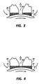
- the cleaning apparatus in the embodiment shown in Figure 3 includes open-cell foam pad 21 adhered to the face of a cleaner housing 22 adjacent to a slit opening 23.
- a vacuum source 10 provides a negative pressure to slit 23.
- the foam pad covers the face of a surface of cleaner housing 22 adjacent photoconductive surface 1 but does not cover slit 23.
- the foam is pressed gently into sliding contact with the imaging surface to be cleaned and recycled for further imaging. In this way, the foam acts like a random array of cleaning blades, and also permits loosened toner to be carried away by moving air from the vacuum source.
- open-cell foam pad 21 is adhered to the face of cleaner housing 22 as shown in Figure 2, but this time is covering slit opening 23.
- the foam covered slit is brought into contact with the imaging surface (photoreceptor or electroreceptor) or photoconductive surface 1 in order to loosen and sweep residual toner away from the photoconductive surface.
- the cleaner embodiment of Figure 2 is preferred over this embodiment because if the foam bridges across the slit, there will be zero air velocity at the photoconductive surface at the center of the slit. With either embodiment, very little space is occupied around the drum on which the photoconductive surface is mounted and air blower power is lessened. Conducting or non-conducting pads could be used, if desired. Also, a seamed image surface can be beneficial for use with this invention in that "declogging" of the foam pads could be accomplished.
- a low cost vacuum cleaner in which fiber-like bristles are adhered to the face of a slit through which air is pulled by a vacuum pump and the foam is pressed gently into sliding contact with the imaging surface to be cleaned and recycled. This method of cleaning allows agitation of toner to take place where the air flow is greatest.
Abstract
Description
- The present invention relates to an improved cleaning method and apparatus that collects residual toner from the photoconductive surface of an electrophotographic copying machine by using a vacuum slit and fiber-like bristles or open-cell foam padding.
- Conventionally, there are a variety of methods used for cleaning residual toner from the surface of a photoconductor. For example, U. S. Patent 3,536,528 discloses a method and apparatus for cleaning toner particles form the surface of a web. The removal of freed particles from the vicinity of the web material is achieved by one or more air currents maintained by suction and/or blowing devices. A cleaning head with wedge-like channels having a rectangular cross section and a plurality of ducts. Pressurized air is fed therethrough one duct to a channel. Air laden with particles is removed from a web and carried through another of the channels. An ionized air cleaning device is shown in U. S. Patent 3,668,008 for use in an automatic xerographic reproducing machine. The apparatus is adapted to clean residual toner powder images from a photoreceptor where an ionized air flows to the surface to be cleaned and neutralizes the particles thereon to allow the particles to be readily removed. The ionized flow may be directed against the surface to neutralize the particles, allowing for removal by a brush or vacuum nozzle. In U. S. Patent 3,743,540 a method and apparatus for cleaning a residual toner powder image surface by ionized flow is shown. Fans or air pumps are utilized to direct a flow of ionized air to the surface to be cleaned. The air flow neutralizes any charge of the residual particles remaining on the surface to allow the particles to be readily removed. U. S. Patent 4,014,065 discloses a vacuum removal means for removing excessive developer material from a member having a latent magnetic image developed with magnetic developer material. The vacuum removal means comprises a chamber having entrance and exit ports sized such that the ratio of entrance port to exit port is sufficiently small to assure substantial uniform air flow across the entrance port when the chamber is subjected to a negative pressure through the exit port. In U. S. Patent 4,121,947 a method of cleaning a photoreceptor includes the steps of exposing a photoconductive layer of the photoreceptor to light, charging the photoconductive layer, vibrating the photoreceptor to dislodge the toner therefrom and subjecting the toner to a force such as vacuum or gravity which draws the toner away from the photoreceptor. U. S. Patent 4,610,534 discloses a cleaning device for copying machines which collects residual toner from a photoconductive surface of a copy machine by using a rotary brush and deposits the collected toner into a specific part such as a filter. The residual toner is forced into the filter by a vacuum means which includes an air duct formed between a specific part of the rotary brush and a vacuum activating fan mounted inside the air duct. All of the above-referenced patents are included herein by reference to the extent necessary to practice the present invention.
- As is now apparent, common methods of cleaning in use in current copiers are brush cleaning, web cleaning, blade cleaning and electrostatic brush (magnetic brush or carrier bead) cleaning. Fur brush cleaning has been used since the 1950s. The complexity of a high speed rotating brush makes it costly and it is also space consuming. Web cleaning dates back to the 1960s and its main problem is the cost of consumable webs, spooling of the web supply and of the take-up means. Blade cleaning is compact, but susceptible to nicking, lint collection, and "tuck under" problems. It also requires smoother photoreceptors, and needs self-lubricating developers (such as one percent Kynar).
- Electrostatic "developer" cleaning requires complete manual cleaning out of the equipment too frequently, or the use of forced air and a filter bag. Accordingly, if one must use forced air and a filter bag anyway, the present invention adds a compact, no moving parts (except for the air blower) cleaning method and apparatus which uses a vacuum slit and fiber-like bristles or open-cell foam padding. The foam covered or non-covered slit is pressed lightly into sliding contact with an imaging surface to be cleaned, the foam padding acting like a random array of cleaning blades permitting toner to be carried away by the moving air. Similarly, the fiber-like bristles are adapted for positioning in sliding contact with an imaging surface and connected to a vacuum source such that toner that is loosened on the imaging surface by the fiber-like bristles is suctioned off the imaging surface by the vacuum source.
- The above-mentioned features and others of the invention, together with the manner of obtaining them will be best understood by making reference to the following specification in conjunction with the accompanying drawings, wherein:
- Figure 1 is a simplified block diagram of a conventional copying machine containing a cleaning system as a preferred embodiment of the present invention.
- Figure 2 is an enlarged, partial side view of the cleaning system of Figure 1.
- Figure 3 is an enlarged, partial side view of an alternative embodiment of the cleaning system of Figure 1.
- Figure 4 is an enlarged, partial side view of yet another alternative embodiment of the cleaning system of the present invention.
- While the present invention will hereinafter be described in connection with a preferred embodiment thereof, it will be understood that it is not intended to limit the invention to that embodiment. On the contrary, it is intended to cover all alternatives, modifications and equivalents as may be included within the spirit and scope of the invention as defined by the appended claims.
- For a general understanding of the features of the present invention, reference is had to the drawings. In the drawings, like reference numerals have been used throughout to designate identical elements. Figure 1 schematically depicts the various components of an illustrative electrophotographic copying machine incorporating the cleaning apparatus of the present invention therein.
- Inasmuch as the art of electrophotographic recording is well known, the various processing stations employed in the Figure 1 recording machine will be shown hereinafter schematically and their operation described briefly with reference thereto.
- Referring now to Figure 1, there is shown by way of example, an automatic
electrostatographic recording machine 10 that could be electrophotographic or electrographic, such as, ionographic means for latent image formation which includes a toner cleaning system. The reproducing machine depicted in Figure 1 illustrates the various components utilized therein for producing copies from an original document. Although the apparatus of the present invention is particularly well adapted for use with automatic electrostatographic reproducing machines, it should become evident from the following description that it is equally well suited for use in a wide variety of processing systems including other electrostatographic systems and is not necessarily limited in application to the particular embodiment or embodiments shown herein. - The conventional reproducing machine illustrated in Figure 1 employs the above-mentioned cleaning method and apparatus in which corona discharger 2, developer brush 3, transfer corona charger 4, charge corona charger 5,
cleaning unit 20, and discharge lamp 7, are respectively provided around the photoconductive surface 1 at proper intervals. A latent image is formed on the photoconductive surface 1 by corona charger 2 and exposure light 8 and is developed by developer brush 3 before being transferred onto a copying paper by the transfer corona charger 4. After a transfer operation is completed, residual toner is then removed from the photoconductive surface 1 by neutralizing with corona discharger 5 and cleaning withcleaner 20 in accordance with the present invention before being sent to a filter 9 by aconventional vacuum source 10. Filter 9 is provided with afilter bag 90 containing an air filter that collects toner from the cleaner for deposit. Avacuum unit 10 absorbs the removed toner from thecleaner 20 into filter 9 and is provided above the filter. It should be understood that thecleaning device 20 is just as effective in a printer as a copier and with belt photoreceptors as with drum shaped photoreceptors, and also with belt or drum charge receptors in ionographic printers. - The
cleaning apparatus 20 in the preferred embodiment shown in Figure 2 comprises short velvet-like or fiber-like flockedbristles 16 embedded in or adhered to an impervious material. Contact with photoreceptor 1 is gentle and non-abrasive and resistance to air flow through the flocked bristles is minimal. A seamed photoreceptor will provide a "flicking" action to shake loose any adhering toner particles from the fibers. In operation, vacuum flow fromvacuum source 10 of about 12 cm of water produces adequate air velocity where the fibrous, airpervious layer 16 rubs against and loosens the toner on the surface of rotating photoreceptor 1, so that the toner is carried into and thru aslit 23 where it passes intofilter bag 90. The vacuum slit is preferably about 2.5 mm wide while the surfaces ofhousing 22 that are opposite photoreceptor 1 extend about 3 mm and bristles 16 (which comprise high pile precision acrylic fibers) are about 25 micrometers in diameter with a length of about 1.0 mm and a density of about 300,000/cm². - The cleaning apparatus in the embodiment shown in Figure 3, includes open-
cell foam pad 21 adhered to the face of acleaner housing 22 adjacent to a slit opening 23. Avacuum source 10 provides a negative pressure to slit 23. The foam pad covers the face of a surface ofcleaner housing 22 adjacent photoconductive surface 1 but does not coverslit 23. The foam is pressed gently into sliding contact with the imaging surface to be cleaned and recycled for further imaging. In this way, the foam acts like a random array of cleaning blades, and also permits loosened toner to be carried away by moving air from the vacuum source. - Alternatively, as shown in Figure 4, open-
cell foam pad 21 is adhered to the face ofcleaner housing 22 as shown in Figure 2, but this time is covering slit opening 23. In use, the foam covered slit is brought into contact with the imaging surface (photoreceptor or electroreceptor) or photoconductive surface 1 in order to loosen and sweep residual toner away from the photoconductive surface. The cleaner embodiment of Figure 2 is preferred over this embodiment because if the foam bridges across the slit, there will be zero air velocity at the photoconductive surface at the center of the slit. With either embodiment, very little space is occupied around the drum on which the photoconductive surface is mounted and air blower power is lessened. Conducting or non-conducting pads could be used, if desired. Also, a seamed image surface can be beneficial for use with this invention in that "declogging" of the foam pads could be accomplished. - In summary, a low cost vacuum cleaner is disclosed in which fiber-like bristles are adhered to the face of a slit through which air is pulled by a vacuum pump and the foam is pressed gently into sliding contact with the imaging surface to be cleaned and recycled. This method of cleaning allows agitation of toner to take place where the air flow is greatest.
- While this invention has been described with reference to the structures disclosed herein, they are not confined to the details as set forth and are intended to cover modifications and changes that may come within the scope of the following claims.
Claims (11)
- A cleaning device for removing residual toner from an imaging surface, comprising:
a housing means having a surface thereof with a slit therethrough; and
open-cell foam means adhered to said surface of said housing adjacent said slit and adapted for positioning in sliding contact with an imaging surface. - The cleaning device of claim 1, wherein said housing means includes a vacuum source adapted to suction toner through said slit loosened on an imaging surface by said foam means.
- The cleaning device of claim 2, including an imaging member and wherein said imaging surface includes at least one seam.
- A method for removing residual toner from an imaging surface, comprising the steps of:
providing a housing means having a surface thereof with a slit therethrough; and
providing open-cell foam means adhered to said surface of said housing adjacent said slit and adapted for positioning in sliding contact with an imaging surface. - The method of claim 4, including the step of providing a vacuum source adapted to suction toner that is loosened on an imaging surface by said foam means into and through said slit.
- A cleaning device for removing residual toner from an imaging surface, comprising:
a housing means having a surface thereof with a slit therethrough; and
open-cell foam means adhered to said surface of said housing and covering said slit and adapted for positioning in sliding contact with an imaging surface. - The cleaning device of claim 6, wherein said housing means includes a vacuum source adapted to suction toner that is loosened on an imaging surface by said foam means into and through said slit.
- A cleaning device for removing residual toner from an imaging surface, comprising:
a housing means having a surface thereof with a slit therethrough; and
fiber-like bristle means adhered to said surface of said housing adjacent said slit and adapted for positioning in sliding contact with an imaging surface. - The cleaning device of claim 8, wherein said housing means includes a vacuum source adapted to suction toner that is loosened on an imaging surface by said fiber-like bristle means into and through said slit.
- A method for removing residual toner from an imaging surface, comprising the steps of:
providing a housing means having a surface thereof with a slit therethrough; and
providing fiber-like bristle means adhered to said surface of said housing adjacent said slit and adapted for positioning in sliding contact with an imaging surface. - The method of claim 10, including the step of providing a vacuum source adapted to suction toner that is loosened on an imaging surface by said fiber-like bristle means into and through said slit.
Applications Claiming Priority (2)
| Application Number | Priority Date | Filing Date | Title |
|---|---|---|---|
| US07/544,439 US5121167A (en) | 1990-06-27 | 1990-06-27 | Sweep and vacuum xerographic cleaning method and apparatus |
| US544439 | 1990-06-27 |
Publications (2)
| Publication Number | Publication Date |
|---|---|
| EP0463399A2 true EP0463399A2 (en) | 1992-01-02 |
| EP0463399A3 EP0463399A3 (en) | 1992-11-19 |
Family
ID=24172200
Family Applications (1)
| Application Number | Title | Priority Date | Filing Date |
|---|---|---|---|
| EP19910109011 Withdrawn EP0463399A3 (en) | 1990-06-27 | 1991-06-03 | Sweep and vacuum xerographic cleaning method and apparatus |
Country Status (3)
| Country | Link |
|---|---|
| US (1) | US5121167A (en) |
| EP (1) | EP0463399A3 (en) |
| JP (1) | JPH04233571A (en) |
Cited By (1)
| Publication number | Priority date | Publication date | Assignee | Title |
|---|---|---|---|---|
| DE102005027588A1 (en) * | 2005-06-14 | 2007-01-18 | Eastman Kodak Co. | Powdered toner particles removing device for electrographically operating printing machine, has cleaning unit operating like scraper, where unit is combined with vacuum cleaner whose suction head is integrated in wiper blade |
Families Citing this family (6)
| Publication number | Priority date | Publication date | Assignee | Title |
|---|---|---|---|---|
| JP3078037B2 (en) * | 1991-06-21 | 2000-08-21 | 株式会社東芝 | Image forming device |
| US5332642A (en) * | 1991-10-18 | 1994-07-26 | Xerox Corporation | Vacuum assisted dispersant reduction system |
| US5751329A (en) * | 1994-03-04 | 1998-05-12 | Hewlett-Packard Company | Ionographic color printer with plural print heads removable toner cartridge and one-time usable polymeric web |
| US6553205B1 (en) | 2001-12-14 | 2003-04-22 | Xerox Corporation | System for toner cleaning |
| JP4857637B2 (en) * | 2005-07-27 | 2012-01-18 | ブラザー工業株式会社 | Cleaning member for photoreceptor, photoreceptor cartridge having the same, and image forming apparatus |
| CN107678265B (en) * | 2017-09-27 | 2020-12-29 | 珠海意动智能装备有限公司 | Toner cartridge regeneration and recovery system and method for recovering residual toner |
Citations (3)
| Publication number | Priority date | Publication date | Assignee | Title |
|---|---|---|---|---|
| US3395042A (en) * | 1966-03-18 | 1968-07-30 | William C. Herbert Jr. | Paper-cleaning apparatus |
| FR2136634A5 (en) * | 1971-04-24 | 1972-12-22 | Kalle Ag | |
| US4014065A (en) * | 1975-08-27 | 1977-03-29 | Xerox Corporation | Magnetic developer removal system |
Family Cites Families (18)
| Publication number | Priority date | Publication date | Assignee | Title |
|---|---|---|---|---|
| GB1181368A (en) * | 1967-08-16 | 1970-02-18 | Agfa Gevaert Nv | Electrostatic cleaner |
| US3668008A (en) * | 1969-06-04 | 1972-06-06 | Xerox Corp | Ionized air cleaning device |
| US3570224A (en) * | 1969-11-17 | 1971-03-16 | Xerox Corp | Filter for electrostatographic developer |
| BE758141A (en) * | 1969-12-29 | 1971-04-01 | Ibm | DEVICE FOR CLEANING SURFACES AND IN PARTICULAR XEROGRAPHIC CLICHES |
| US3743540A (en) * | 1971-08-30 | 1973-07-03 | F Hudson | Surface cleaning by ionized flow |
| BE792642A (en) * | 1971-12-22 | 1973-03-30 | Ibm | DEVICE FOR CLEANING AN ELECTROSTATIC IMAGE SUPPORT FOR USE IN AN ELECTROPHOTOGRAPHIC REPRODUCTION APPARATUS |
| US3807853A (en) * | 1972-08-09 | 1974-04-30 | Xerox Corp | Electrophotographic cleaning apparatus |
| US3795025A (en) * | 1972-11-21 | 1974-03-05 | Xerox Corp | Electrophotographic photoreceptor cleaning apparatus |
| US4026701A (en) * | 1975-02-24 | 1977-05-31 | Xerox Corporation | Gas impingement and suction cleaning apparatus |
| US4007983A (en) * | 1975-10-29 | 1977-02-15 | Xerox Corporation | Liquid developer cleaning means |
| US4121947A (en) * | 1977-07-05 | 1978-10-24 | Xerox Corporation | Method of cleaning a photoreceptor |
| JPS58125079A (en) * | 1982-01-20 | 1983-07-25 | Ricoh Co Ltd | Cleaning device for image carrier |
| JPS59153565U (en) * | 1983-03-31 | 1984-10-15 | シャープ株式会社 | cleaning equipment |
| JPS6011869A (en) * | 1983-07-01 | 1985-01-22 | Fuji Xerox Co Ltd | Cleaning device of electrophotography copying machine |
| US4522488A (en) * | 1983-12-21 | 1985-06-11 | Xerox Corporation | Cleaning apparatus for a magnetographic printing device |
| JPH0622862Y2 (en) * | 1986-09-22 | 1994-06-15 | 三田工業株式会社 | Cleaning device for electrophotographic copying machine |
| JPH01250982A (en) * | 1988-03-30 | 1989-10-05 | Nec Corp | Cleaning mechanism |
| US4878093A (en) * | 1988-10-03 | 1989-10-31 | Xerox Corporation | Dual roll cleaning apparatus for charge retentive surface |
-
1990
- 1990-06-27 US US07/544,439 patent/US5121167A/en not_active Expired - Fee Related
-
1991
- 1991-06-03 EP EP19910109011 patent/EP0463399A3/en not_active Withdrawn
- 1991-06-20 JP JP3149020A patent/JPH04233571A/en not_active Withdrawn
Patent Citations (3)
| Publication number | Priority date | Publication date | Assignee | Title |
|---|---|---|---|---|
| US3395042A (en) * | 1966-03-18 | 1968-07-30 | William C. Herbert Jr. | Paper-cleaning apparatus |
| FR2136634A5 (en) * | 1971-04-24 | 1972-12-22 | Kalle Ag | |
| US4014065A (en) * | 1975-08-27 | 1977-03-29 | Xerox Corporation | Magnetic developer removal system |
Non-Patent Citations (4)
| Title |
|---|
| IBM TECHNICAL DISCLOSURE BULLETIN. vol. 12, no. 11, April 1970, NEW YORK US page 1819; W. CROOKS: 'ELECTROPHOTOGRAPHIC CLEANING APPARATUS' * |
| PATENT ABSTRACTS OF JAPAN vol. 7, no. 18 (P-170)(1163) 25 January 1983 & JP-A-57 172 379 ( RICOH K.K. ) 23 October 1982 * |
| RESEARCH DISCLOSURE. no. 161, September 1977, HAVANT GB page 14; M.L. STAUB,JR: 'Oscillating cleaner' * |
| RESEARCH DISCLOSURE. no. 214, February 1982, HAVANT GB page 44; DISCLOSURE NØ 21417: 'Web cleaning apparatus' * |
Cited By (1)
| Publication number | Priority date | Publication date | Assignee | Title |
|---|---|---|---|---|
| DE102005027588A1 (en) * | 2005-06-14 | 2007-01-18 | Eastman Kodak Co. | Powdered toner particles removing device for electrographically operating printing machine, has cleaning unit operating like scraper, where unit is combined with vacuum cleaner whose suction head is integrated in wiper blade |
Also Published As
| Publication number | Publication date |
|---|---|
| JPH04233571A (en) | 1992-08-21 |
| US5121167A (en) | 1992-06-09 |
| EP0463399A3 (en) | 1992-11-19 |
Similar Documents
| Publication | Publication Date | Title |
|---|---|---|
| US3807853A (en) | Electrophotographic cleaning apparatus | |
| EP0233589A1 (en) | Cleaning device and multi-color electrophotographic apparatus | |
| US4878093A (en) | Dual roll cleaning apparatus for charge retentive surface | |
| US4518248A (en) | Apparatus for forming image by developing charge latent image with two component dry developing agent | |
| US4134673A (en) | Dual brush cleaning apparatus | |
| US5121167A (en) | Sweep and vacuum xerographic cleaning method and apparatus | |
| US5576822A (en) | Ultrasonic transducer for brush detoning assist | |
| JPH0259997B2 (en) | ||
| JP3283631B2 (en) | Cleaning device for removing residual toner | |
| US5381218A (en) | Conductive cleaning brush belt and detoning thereof | |
| US6169872B1 (en) | Electrostatic cleaning belt brush | |
| EP0639804B1 (en) | Apparatus for removing residual developer material from a surface of a printing machine | |
| JPH04267282A (en) | Cleanerless image formation device | |
| US5561513A (en) | Enhanced brush detoning by rotating the detoning roll in the "with" direction | |
| US5241352A (en) | Air detoned cleaner brush | |
| EP0602928A2 (en) | Xerographic brush cleaner detoner | |
| JP4068725B2 (en) | Development device | |
| JPH04371977A (en) | Electrophotographic recorder | |
| JPH03246571A (en) | Developing device provided with cleaning means | |
| JP2000194242A (en) | Image forming device | |
| JPS5911909B2 (en) | electrophotographic copying device | |
| JPH0675510A (en) | Cleaning device | |
| JP2004020690A (en) | Image forming apparatus | |
| JPS6135475A (en) | Cleaning device of electrophotographic copying machine | |
| JPS58107570A (en) | Cleaning device |
Legal Events
| Date | Code | Title | Description |
|---|---|---|---|
| PUAI | Public reference made under article 153(3) epc to a published international application that has entered the european phase |
Free format text: ORIGINAL CODE: 0009012 |
|
| AK | Designated contracting states |
Kind code of ref document: A2 Designated state(s): DE FR GB |
|
| PUAL | Search report despatched |
Free format text: ORIGINAL CODE: 0009013 |
|
| AK | Designated contracting states |
Kind code of ref document: A3 Designated state(s): DE FR GB |
|
| 17P | Request for examination filed |
Effective date: 19930518 |
|
| 17Q | First examination report despatched |
Effective date: 19930720 |
|
| STAA | Information on the status of an ep patent application or granted ep patent |
Free format text: STATUS: THE APPLICATION IS DEEMED TO BE WITHDRAWN |
|
| 18D | Application deemed to be withdrawn |
Effective date: 19930131 |