EP0716245B1 - Drum brake assembly - Google Patents
Drum brake assembly Download PDFInfo
- Publication number
- EP0716245B1 EP0716245B1 EP95306755A EP95306755A EP0716245B1 EP 0716245 B1 EP0716245 B1 EP 0716245B1 EP 95306755 A EP95306755 A EP 95306755A EP 95306755 A EP95306755 A EP 95306755A EP 0716245 B1 EP0716245 B1 EP 0716245B1
- Authority
- EP
- European Patent Office
- Prior art keywords
- arcuate
- brake shoe
- mass damper
- brake
- slug
- Prior art date
- Legal status (The legal status is an assumption and is not a legal conclusion. Google has not performed a legal analysis and makes no representation as to the accuracy of the status listed.)
- Expired - Lifetime
Links
Images
Classifications
-
- F—MECHANICAL ENGINEERING; LIGHTING; HEATING; WEAPONS; BLASTING
- F16—ENGINEERING ELEMENTS AND UNITS; GENERAL MEASURES FOR PRODUCING AND MAINTAINING EFFECTIVE FUNCTIONING OF MACHINES OR INSTALLATIONS; THERMAL INSULATION IN GENERAL
- F16D—COUPLINGS FOR TRANSMITTING ROTATION; CLUTCHES; BRAKES
- F16D65/00—Parts or details
- F16D65/0006—Noise or vibration control
- F16D65/0018—Dynamic vibration dampers, e.g. mass-spring systems
-
- F—MECHANICAL ENGINEERING; LIGHTING; HEATING; WEAPONS; BLASTING
- F16—ENGINEERING ELEMENTS AND UNITS; GENERAL MEASURES FOR PRODUCING AND MAINTAINING EFFECTIVE FUNCTIONING OF MACHINES OR INSTALLATIONS; THERMAL INSULATION IN GENERAL
- F16D—COUPLINGS FOR TRANSMITTING ROTATION; CLUTCHES; BRAKES
- F16D65/00—Parts or details
- F16D65/0006—Noise or vibration control
-
- F—MECHANICAL ENGINEERING; LIGHTING; HEATING; WEAPONS; BLASTING
- F16—ENGINEERING ELEMENTS AND UNITS; GENERAL MEASURES FOR PRODUCING AND MAINTAINING EFFECTIVE FUNCTIONING OF MACHINES OR INSTALLATIONS; THERMAL INSULATION IN GENERAL
- F16D—COUPLINGS FOR TRANSMITTING ROTATION; CLUTCHES; BRAKES
- F16D65/00—Parts or details
- F16D65/02—Braking members; Mounting thereof
- F16D65/04—Bands, shoes or pads; Pivots or supporting members therefor
- F16D65/08—Bands, shoes or pads; Pivots or supporting members therefor for internally-engaging brakes
Definitions
- This invention relates generally to a drum brake assembly for motor vehicles.
- Drum brake designers have directed significant effort towards reducing the generation of objectionable noise generated during braking application. Recently, as exemplified by U.S. Patent 4,773,512, some of this effort has been directed to examining the contribution of the internal brake shoe to the generation of this noise or squeal.
- the '512 patent discloses non-uniform stiffening and reinforcing of the brake shoe to shift its natural frequency beyond that of the frequency of the objectionable noise being generated. Practising this involves accurately placing several reinforcements between the brake shoe web and the table, or alternatively utilising new blanks for the table to provide upturned flanges.
- the present invention seeks to reduce the objectionable noise generated by brake shoes in a drum brake assembly without requiring new blanks for the table or requiring precision positioning and welding of reinforcements at the intersection of the web and the table.
- the present invention provides a brake shoe for a drum brake assembly, including a mass damper attached to the brake shoe for reducing objectionable noises emanating therefrom.
- a brake shoe for use in a drum brake of a motor vehicle, said brake shoe comprising:
- FIG. 1 illustrates a drum brake assembly 10 for a motor vehicle.
- the drum brake assembly 10 includes a brake backing plate 12 having a primary brake shoe 14 and a secondary brake shoe 16 pivotally secured to the backing plate 12 by steady rest springs 18, 20 and pins 22, 24.
- An anchor pin 26 is rigidly attached to the backing plate 12.
- a brake drum 28 surrounds the brake shoes 14, 16 in spaced relation and attaches to a rotating wheel assembly (not shown). Brake linings 30, 32 on the brake shoes 14, 16 are moved against an inner surface of the brake drum 28 by a wheel cylinder 34 for frictionally stopping the motor vehicle.
- FIG. 2 illustrates the primary brake shoe 14, which will now be described, it being understood that the secondary brake shoe 16 is a mirror image of the primary brake shoe 14 for the purposes of this description.
- the brake shoe 14 includes an arcuate table 40 having a web 46 fixed to an inner periphery 42 substantially midway between opposite arcuate edges 48, 50 of the arcuate table 40.
- the arcuate table 40 further includes an outer periphery 44 to which the lining 30 is fixed between first and second ends 52, 54 of the arcuate table 40.
- the brake shoe 14 also includes a mass damper, shown in the presently preferred form of an arcuate plate 60, fixed to the inner periphery 42 of the arcuate table 40.
- the mass damper provides a concentrated location of mass, that may be shaped as required for packaging the neighbouring components within the drum brake assembly 10.
- the arcuate plate 60 includes inner and outer peripheries 62, 64 about one quarter of an inch (6.5 mm) apart and parallel to the inner periphery 42 of the arcuate table 40.
- the arcuate plate 60 further includes opposite arcuate edges 66, 68 about one inch (25 mm) apart and first and second ends 70, 72 about two and a half inches (63 mm) apart.
- the present invention is not so limited, however, as various shaped slugs of material are contemplated for conforming within the limited space available in the drum brake assembly 10.
- One such example contemplated includes a cylindrical body having one end resiliently attached to the internal periphery 42 of the arcuate table 40.
- a protuberance 74 projects from the outer periphery 64 of the arcuate plate 60 toward the inner periphery 42 of the arcuate table 40.
- the arcuate plate 60 is stamped from mild steel, which allows the protuberance 74 to be projection welded to the inner periphery 42 of the arcuate table 40 when constructed from a weld compatible material. This provides the most cost effective manner of attaching the mass damper to the arcuate table 40, however, the present invention is not so limited. Alternative fastening techniques may be required for materials not capable of welding.
- the mass damper may be bonded, riveted or secured by a threaded fastener while providing the equivalent function and operability.
- the position of the mass damper on the arcuate table 40 is preferably determined through testing the drum brake assembly 10.
- an objectionable noise in the frequency range of 8-14 khz, emanates from the drum brake assembly 10 during operation it can be traced, at least in part, to a torsional vibration mode of the brake shoe 14.
- This vibration mode is characterised in that the arcuate table 40 undergoes what is referred to as flutter.
- the opposite arcuate edges 48, 50 at a particular point between the first and second ends 52, 54 of the arcuate table 40 experience an out-of-phase sinusoidal displacement. This point is referred to as an anti-node.
- a brake shoe 14 having an arcuate table 40 being twelve inches (30 cm) between first and second ends 52, 54 and three inches (7.5 cm) between opposite edges 48, 50
- the arcuate plate 60 is best positioned-midway between the first and second ends 52, 54 adjacent to one of the opposite edges, 48, 50.
- two arcuate plates 60 are preferred for a brake shoe 14 having an arcuate table 40 being twelve and one-eighth inches (30.8 cm) between with first and second ends 52, 54 and three and one-half inches (3.9 cm) between opposite edges 48, 50.
- a first arcuate plate is positioned substantially midway between a first end 52 and a midpoint 56 of the arcuate table 40, and a second arcuate plate 60 is positioned substantially midway between a second end 54 and the midpoint 56 of the arcuate table 40.
Landscapes
- Engineering & Computer Science (AREA)
- General Engineering & Computer Science (AREA)
- Mechanical Engineering (AREA)
- Braking Arrangements (AREA)
Description
- This invention relates generally to a drum brake assembly for motor vehicles.
- Drum brake designers have directed significant effort towards reducing the generation of objectionable noise generated during braking application. Recently, as exemplified by U.S. Patent 4,773,512, some of this effort has been directed to examining the contribution of the internal brake shoe to the generation of this noise or squeal. The '512 patent discloses non-uniform stiffening and reinforcing of the brake shoe to shift its natural frequency beyond that of the frequency of the objectionable noise being generated. Practising this involves accurately placing several reinforcements between the brake shoe web and the table, or alternatively utilising new blanks for the table to provide upturned flanges.
- The present invention seeks to reduce the objectionable noise generated by brake shoes in a drum brake assembly without requiring new blanks for the table or requiring precision positioning and welding of reinforcements at the intersection of the web and the table.
- The present invention provides a brake shoe for a drum brake assembly, including a mass damper attached to the brake shoe for reducing objectionable noises emanating therefrom.
- In accordance with the present invention, there is provided a brake shoe for use in a drum brake of a motor vehicle, said brake shoe comprising:
- an arcuate table having inner and outer peripheries;
- a web fixed to the inner periphery of said table substantially midway between opposite arcuate edges of said arcuate table;
- a lining secured to said outer periphery of said table, said lining being operative to effect braking contact with a brake drum; characterised in that;
-
- It is an advantage of the mass damper that it attenuates torsional vibration of the brake shoe and thereby reduces objectionable noises emanating therefrom.
- The invention will now be described further, by way of example, with reference to the accompanying drawings, in which :-
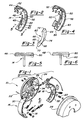
- FIG. 1 is an exploded view of an internal drum brake assembly having brake shoes fitted with mass dampers according to the present invention,
- FIG. 2 is a perspective view of a brake shoe having a mass damper according to the present invention,
- FIG. 3 is a perspective view of a mass damper in the form of an arcuate plate according to the present invention,
- FIG. 4 is a perspective view of an alternative embodiment of a brake shoe requiring two mass dampers according to the present invention,
- FIG. 5 is a sectional view taken from Fig. 2 showing an arcuate table undergoing a flutter mode of vibration, and
- FIG. 6 is a sectional view taken from Fig. 3 showing a mass damper disposed along an arcuate edge of an arcuate table to attenuate a flutter mode of vibration according to the present invention.
-
- Referring now to the figures, FIG. 1 illustrates a
drum brake assembly 10 for a motor vehicle. Thedrum brake assembly 10 includes abrake backing plate 12 having aprimary brake shoe 14 and asecondary brake shoe 16 pivotally secured to thebacking plate 12 bysteady rest springs pins anchor pin 26 is rigidly attached to thebacking plate 12. Abrake drum 28 surrounds thebrake shoes Brake linings brake shoes brake drum 28 by awheel cylinder 34 for frictionally stopping the motor vehicle. - FIG. 2 illustrates the
primary brake shoe 14, which will now be described, it being understood that thesecondary brake shoe 16 is a mirror image of theprimary brake shoe 14 for the purposes of this description. Thebrake shoe 14 includes an arcuate table 40 having aweb 46 fixed to aninner periphery 42 substantially midway between oppositearcuate edges outer periphery 44 to which thelining 30 is fixed between first andsecond ends brake shoe 14 also includes a mass damper, shown in the presently preferred form of anarcuate plate 60, fixed to theinner periphery 42 of the arcuate table 40. - Referring to Figs. 2 and 3, the mass damper provides a concentrated location of mass, that may be shaped as required for packaging the neighbouring components within the
drum brake assembly 10. In the preferred embodiment, thearcuate plate 60 includes inner andouter peripheries inner periphery 42 of the arcuate table 40. Thearcuate plate 60 further includes oppositearcuate edges second ends drum brake assembly 10. One such example contemplated includes a cylindrical body having one end resiliently attached to theinternal periphery 42 of the arcuate table 40. - A
protuberance 74 projects from theouter periphery 64 of thearcuate plate 60 toward theinner periphery 42 of the arcuate table 40. In the preferred embodiment, thearcuate plate 60 is stamped from mild steel, which allows theprotuberance 74 to be projection welded to theinner periphery 42 of the arcuate table 40 when constructed from a weld compatible material. This provides the most cost effective manner of attaching the mass damper to the arcuate table 40, however, the present invention is not so limited. Alternative fastening techniques may be required for materials not capable of welding. For example, the mass damper may be bonded, riveted or secured by a threaded fastener while providing the equivalent function and operability. - Referring now to Figs. 5 and 6, the position of the mass damper on the arcuate table 40 is preferably determined through testing the
drum brake assembly 10. Generally, when an objectionable noise, in the frequency range of 8-14 khz, emanates from thedrum brake assembly 10 during operation it can be traced, at least in part, to a torsional vibration mode of thebrake shoe 14. This vibration mode is characterised in that the arcuate table 40 undergoes what is referred to as flutter. At a characteristic frequency unique for each drum brake design, the oppositearcuate edges second ends - Referring to Figs. 2 and 3, testing has indicated that for a
brake shoe 14 having an arcuate table 40 being twelve inches (30 cm) between first andsecond ends opposite edges arcuate plate 60 is best positioned-midway between the first andsecond ends brake shoe 14 having an arcuate table 40 being twelve and one-eighth inches (30.8 cm) between with first andsecond ends opposite edges arcuate plates 60 are preferred. A first arcuate plate is positioned substantially midway between afirst end 52 and amidpoint 56 of the arcuate table 40, and a secondarcuate plate 60 is positioned substantially midway between asecond end 54 and themidpoint 56 of the arcuate table 40.
a mass damper is fastened to the arcuate table in a position on said inner periphery of said arcuate table adjacent to an arcuate edge and close to an anti-node of the arcuate table, said mass damper providing a concentrated location of mass operative to attenuate torsional vibration of said brake shoe and thereby reduce objectionable noises emanating therefrom.
Claims (7)
- A brake shoe for use in a drum brake (10) of a motor vehicle, said brake shoe comprising:characterised in that;an arcuate table (40) having inner and outer peripheries;a web (46) fixed to the inner periphery of said table (40) substantially midway between opposite arcuate edges (48,50) of said arcuate table (40);a lining (30) secured to said outer periphery of said table (40), said lining (30) being operative to effect braking contact with a brake drum (28);
a mass damper (60) is fastened to the arcuate table (40) in a position on said inner periphery of said arcuate table (40) adjacent to an arcuate edge (50) and close to an anti-node of the arcuate table (40), said mass damper (60) providing a concentrated location of mass operative to attenuate torsional vibration of said brake shoe (14) and thereby reduce objectionable noises emanating therefrom. - A brake shoe as claimed in claim 1, wherein said mass damper (60) comprises an arcuate slug fastened midway between first and second ends (52,54) of said arcuate table (40).
- A brake shoe as claimed in claim 1, wherein said mass damper (60) comprises a first arcuate slug fastened substantially between a first end (52) and a midpoint (56) of said arcuate table (40), and a second arcuate slug fastened substantially midway between a second end (54) and said midpoint (56) of said arcuate table (40).
- A brake shoe as claimed in any preceding claim, wherein said mass damper (60) is projection welded to said arcuate table (40).
- A brake shoe as claimed in claim 2 or 3, wherein the or each arcuate slug comprises:an arcuate plate (60) having inner (62) and outer (64) peripheries parallel to the said inner and outer peripheries of said arcuate table (40);a protuberance (74) projecting from said outer periphery (64) of aid arcuate plate (60) toward said inner periphery of said arcuate table (40), said protuberance adapted to be projection welded to said arcuate table (40).
- A brake shoe as claimed in claim 5, wherein said arcuate plate (60) is constructed from mild steel.
- A brake shoe as claimed in claim 5 or 6, wherein said arcuate plate (60) comprises;opposite arcuate edges about one inch (2.5 cm.) apart,first and second ends (70,72) about one and one-half inches (3.8 cm.) apart; andsaid inner and outer peripheries (62,64) being about one quarter of an inch (6.5 mm.) apart.
Applications Claiming Priority (2)
| Application Number | Priority Date | Filing Date | Title |
|---|---|---|---|
| US08/349,574 US5515952A (en) | 1994-12-05 | 1994-12-05 | Drum brake assembly including brake shoes with mass dampening |
| US349574 | 1994-12-05 |
Publications (2)
| Publication Number | Publication Date |
|---|---|
| EP0716245A1 EP0716245A1 (en) | 1996-06-12 |
| EP0716245B1 true EP0716245B1 (en) | 2000-03-15 |
Family
ID=23372997
Family Applications (1)
| Application Number | Title | Priority Date | Filing Date |
|---|---|---|---|
| EP95306755A Expired - Lifetime EP0716245B1 (en) | 1994-12-05 | 1995-09-25 | Drum brake assembly |
Country Status (3)
| Country | Link |
|---|---|
| US (1) | US5515952A (en) |
| EP (1) | EP0716245B1 (en) |
| DE (1) | DE69515607T2 (en) |
Families Citing this family (14)
| Publication number | Priority date | Publication date | Assignee | Title |
|---|---|---|---|---|
| US6336533B1 (en) | 2000-06-09 | 2002-01-08 | Dana Corporation | Noise dampening brake shoe |
| US6345712B1 (en) | 2000-06-09 | 2002-02-12 | Dana Corporation | Axle assembly with liquid cooled brake |
| US7032723B2 (en) * | 2002-10-22 | 2006-04-25 | Ford Global Technologies, Llc | Brake assembly with tuned mass damper |
| US20080087508A1 (en) * | 2006-10-16 | 2008-04-17 | Kenmode Tool And Engineering, Inc. | Drum brake adjusters |
| JP4984273B2 (en) * | 2007-06-27 | 2012-07-25 | フレニ ブレンボ エス.ピー.エー. | Disc brake pad |
| US9033119B2 (en) * | 2008-07-18 | 2015-05-19 | Bendix Spicer Foundation Brake Llc | Double dogleg wide stance brake shoe web |
| FR2947022B1 (en) * | 2009-06-17 | 2012-08-24 | Sonomev Freins | SEGMENT FOR DRUM BRAKE, AND DRUM BRAKE |
| US20110127124A1 (en) * | 2009-12-01 | 2011-06-02 | Gm Global Technology Operations, Inc. | Coulomb Friction Damped Disc Brake Caliper Bracket |
| US10428883B2 (en) * | 2015-07-17 | 2019-10-01 | Bendix Spicer Foundation Brake Llc | Drum brake assembly configured to reduce audible noise during braking |
| US20170146080A1 (en) | 2015-11-23 | 2017-05-25 | Bendix Spicer Foundation Brake Llc | Noise Dampening Brake Shoe for a Drum Brake |
| CN110439941B (en) * | 2019-08-20 | 2020-12-29 | 重庆中帝机械制造股份有限公司 | High-stability cast forging type impact welding brake shoe |
| US11739804B2 (en) | 2020-02-18 | 2023-08-29 | Bendix Commercial Vehicle Systems Llc | Drum brake shoe with vibration damping supports |
| CN114310021A (en) * | 2021-12-31 | 2022-04-12 | 泰州市扬帆车件有限公司 | Special equipment for welding braking part of braking system |
| KR20250015331A (en) * | 2023-07-25 | 2025-02-03 | 에이치엘만도 주식회사 | Drum brake |
Family Cites Families (8)
| Publication number | Priority date | Publication date | Assignee | Title |
|---|---|---|---|---|
| JPS5264569A (en) * | 1975-11-26 | 1977-05-28 | Akebono Brake Ind Co Ltd | Brake shoe for drum brake |
| JPS57103941A (en) * | 1980-12-18 | 1982-06-28 | Akebono Brake Ind Co Ltd | Brake shoe |
| DE3109992A1 (en) * | 1981-03-14 | 1982-09-23 | DON-Deutschland GmbH, 6200 Wiesbaden | Brake shoe arrangement |
| JPS5813235A (en) * | 1981-07-15 | 1983-01-25 | Yamaha Motor Co Ltd | Drum brake apparatus |
| JPS6127324A (en) * | 1984-07-18 | 1986-02-06 | Nissan Motor Co Ltd | Shoe for drum brake |
| US4708226A (en) * | 1984-09-12 | 1987-11-24 | Autoipari Kutato Es Fejleszto Vallalat | Brake lining, particularly for a vehicle drum brake |
| GB8817007D0 (en) * | 1988-07-16 | 1988-08-17 | Bba Group Plc | Drum brake assembly |
| JP2762266B2 (en) * | 1990-03-31 | 1998-06-04 | 日野自動車工業株式会社 | Brake shoe for drum type brake |
-
1994
- 1994-12-05 US US08/349,574 patent/US5515952A/en not_active Expired - Fee Related
-
1995
- 1995-09-25 EP EP95306755A patent/EP0716245B1/en not_active Expired - Lifetime
- 1995-09-25 DE DE69515607T patent/DE69515607T2/en not_active Expired - Fee Related
Also Published As
| Publication number | Publication date |
|---|---|
| DE69515607T2 (en) | 2000-07-20 |
| DE69515607D1 (en) | 2000-04-20 |
| US5515952A (en) | 1996-05-14 |
| EP0716245A1 (en) | 1996-06-12 |
Similar Documents
| Publication | Publication Date | Title |
|---|---|---|
| US5515952A (en) | Drum brake assembly including brake shoes with mass dampening | |
| US5099961A (en) | Disc brake | |
| US7032723B2 (en) | Brake assembly with tuned mass damper | |
| US5109959A (en) | Disc brake pad assembly which resists radial outward displacement | |
| GB2258505A (en) | Floating-caliper spot-type disc brake for high-powered vehicles | |
| US6234284B1 (en) | Friction pad for a disc brake assembly | |
| US4886147A (en) | Brake arrangement | |
| JPS6319638Y2 (en) | ||
| US8286762B2 (en) | Drum brakes | |
| JP2762266B2 (en) | Brake shoe for drum type brake | |
| JPH052846B2 (en) | ||
| JPH11287266A (en) | Disc brake | |
| JPS59200819A (en) | Caliper for disc brake | |
| US6336533B1 (en) | Noise dampening brake shoe | |
| GB2262145A (en) | Floating-caliper spot-type disc brake for high-powered vehicles | |
| GB2039644A (en) | Vehicle friction brake | |
| JP4077090B2 (en) | Disc brake | |
| JPS6021572Y2 (en) | Power unit displacement regulating device | |
| JPH0423134B2 (en) | ||
| JPH0547300Y2 (en) | ||
| JPH08193630A (en) | Brake drum | |
| JPS60509Y2 (en) | drum brake | |
| JPH03282026A (en) | Drum type brake | |
| JPH03272334A (en) | Brake lining of drum type brake | |
| JPS602346Y2 (en) | disc brake |
Legal Events
| Date | Code | Title | Description |
|---|---|---|---|
| PUAI | Public reference made under article 153(3) epc to a published international application that has entered the european phase |
Free format text: ORIGINAL CODE: 0009012 |
|
| AK | Designated contracting states |
Kind code of ref document: A1 Designated state(s): DE FR GB |
|
| 17P | Request for examination filed |
Effective date: 19961111 |
|
| 17Q | First examination report despatched |
Effective date: 19981117 |
|
| GRAG | Despatch of communication of intention to grant |
Free format text: ORIGINAL CODE: EPIDOS AGRA |
|
| GRAG | Despatch of communication of intention to grant |
Free format text: ORIGINAL CODE: EPIDOS AGRA |
|
| GRAH | Despatch of communication of intention to grant a patent |
Free format text: ORIGINAL CODE: EPIDOS IGRA |
|
| GRAH | Despatch of communication of intention to grant a patent |
Free format text: ORIGINAL CODE: EPIDOS IGRA |
|
| GRAA | (expected) grant |
Free format text: ORIGINAL CODE: 0009210 |
|
| AK | Designated contracting states |
Kind code of ref document: B1 Designated state(s): DE FR GB |
|
| REF | Corresponds to: |
Ref document number: 69515607 Country of ref document: DE Date of ref document: 20000420 |
|
| ET | Fr: translation filed | ||
| REG | Reference to a national code |
Ref country code: FR Ref legal event code: TP |
|
| PLBE | No opposition filed within time limit |
Free format text: ORIGINAL CODE: 0009261 |
|
| STAA | Information on the status of an ep patent application or granted ep patent |
Free format text: STATUS: NO OPPOSITION FILED WITHIN TIME LIMIT |
|
| 26N | No opposition filed | ||
| REG | Reference to a national code |
Ref country code: GB Ref legal event code: IF02 |
|
| PGFP | Annual fee paid to national office [announced via postgrant information from national office to epo] |
Ref country code: GB Payment date: 20030827 Year of fee payment: 9 |
|
| PGFP | Annual fee paid to national office [announced via postgrant information from national office to epo] |
Ref country code: DE Payment date: 20030903 Year of fee payment: 9 |
|
| PGFP | Annual fee paid to national office [announced via postgrant information from national office to epo] |
Ref country code: FR Payment date: 20030904 Year of fee payment: 9 |
|
| PG25 | Lapsed in a contracting state [announced via postgrant information from national office to epo] |
Ref country code: GB Free format text: LAPSE BECAUSE OF NON-PAYMENT OF DUE FEES Effective date: 20040925 |
|
| PG25 | Lapsed in a contracting state [announced via postgrant information from national office to epo] |
Ref country code: DE Free format text: LAPSE BECAUSE OF NON-PAYMENT OF DUE FEES Effective date: 20050401 |
|
| GBPC | Gb: european patent ceased through non-payment of renewal fee |
Effective date: 20040925 |
|
| PG25 | Lapsed in a contracting state [announced via postgrant information from national office to epo] |
Ref country code: FR Free format text: LAPSE BECAUSE OF NON-PAYMENT OF DUE FEES Effective date: 20050531 |
|
| REG | Reference to a national code |
Ref country code: FR Ref legal event code: ST |