EP0715392B1 - Thermal management using a hybrid spiral/helical winding geometry for inductive charger - Google Patents
Thermal management using a hybrid spiral/helical winding geometry for inductive charger Download PDFInfo
- Publication number
- EP0715392B1 EP0715392B1 EP95118969A EP95118969A EP0715392B1 EP 0715392 B1 EP0715392 B1 EP 0715392B1 EP 95118969 A EP95118969 A EP 95118969A EP 95118969 A EP95118969 A EP 95118969A EP 0715392 B1 EP0715392 B1 EP 0715392B1
- Authority
- EP
- European Patent Office
- Prior art keywords
- transformer
- spiral
- charge
- winding
- turns
- Prior art date
- Legal status (The legal status is an assumption and is not a legal conclusion. Google has not performed a legal analysis and makes no representation as to the accuracy of the status listed.)
- Expired - Lifetime
Links
Images



Classifications
-
- B—PERFORMING OPERATIONS; TRANSPORTING
- B60—VEHICLES IN GENERAL
- B60L—PROPULSION OF ELECTRICALLY-PROPELLED VEHICLES; SUPPLYING ELECTRIC POWER FOR AUXILIARY EQUIPMENT OF ELECTRICALLY-PROPELLED VEHICLES; ELECTRODYNAMIC BRAKE SYSTEMS FOR VEHICLES IN GENERAL; MAGNETIC SUSPENSION OR LEVITATION FOR VEHICLES; MONITORING OPERATING VARIABLES OF ELECTRICALLY-PROPELLED VEHICLES; ELECTRIC SAFETY DEVICES FOR ELECTRICALLY-PROPELLED VEHICLES
- B60L53/00—Methods of charging batteries, specially adapted for electric vehicles; Charging stations or on-board charging equipment therefor; Exchange of energy storage elements in electric vehicles
- B60L53/30—Constructional details of charging stations
- B60L53/34—Plug-like or socket-like devices specially adapted for contactless inductive charging of electric vehicles
-
- B—PERFORMING OPERATIONS; TRANSPORTING
- B60—VEHICLES IN GENERAL
- B60L—PROPULSION OF ELECTRICALLY-PROPELLED VEHICLES; SUPPLYING ELECTRIC POWER FOR AUXILIARY EQUIPMENT OF ELECTRICALLY-PROPELLED VEHICLES; ELECTRODYNAMIC BRAKE SYSTEMS FOR VEHICLES IN GENERAL; MAGNETIC SUSPENSION OR LEVITATION FOR VEHICLES; MONITORING OPERATING VARIABLES OF ELECTRICALLY-PROPELLED VEHICLES; ELECTRIC SAFETY DEVICES FOR ELECTRICALLY-PROPELLED VEHICLES
- B60L53/00—Methods of charging batteries, specially adapted for electric vehicles; Charging stations or on-board charging equipment therefor; Exchange of energy storage elements in electric vehicles
- B60L53/10—Methods of charging batteries, specially adapted for electric vehicles; Charging stations or on-board charging equipment therefor; Exchange of energy storage elements in electric vehicles characterised by the energy transfer between the charging station and the vehicle
- B60L53/12—Inductive energy transfer
- B60L53/122—Circuits or methods for driving the primary coil, e.g. supplying electric power to the coil
-
- H—ELECTRICITY
- H01—ELECTRIC ELEMENTS
- H01F—MAGNETS; INDUCTANCES; TRANSFORMERS; SELECTION OF MATERIALS FOR THEIR MAGNETIC PROPERTIES
- H01F38/00—Adaptations of transformers or inductances for specific applications or functions
- H01F38/14—Inductive couplings
-
- H—ELECTRICITY
- H02—GENERATION; CONVERSION OR DISTRIBUTION OF ELECTRIC POWER
- H02J—ELECTRIC POWER NETWORKS; CIRCUIT ARRANGEMENTS OR SYSTEMS FOR SUPPLYING OR DISTRIBUTING ELECTRIC POWER; SYSTEMS FOR STORING ELECTRIC ENERGY
- H02J4/00—Circuit arrangements for mains or distribution networks not specified as AC or DC; Circuit arrangements for mains or distribution networks combining AC and DC sections or sub-networks
- H02J4/20—Networks integrating separated AC and DC power sections
- H02J4/25—Networks integrating separated AC and DC power sections for transfer of electric power between AC and DC networks, e.g. for supplying the DC section within a load from an AC mains system
-
- H—ELECTRICITY
- H02—GENERATION; CONVERSION OR DISTRIBUTION OF ELECTRIC POWER
- H02J—ELECTRIC POWER NETWORKS; CIRCUIT ARRANGEMENTS OR SYSTEMS FOR SUPPLYING OR DISTRIBUTING ELECTRIC POWER; SYSTEMS FOR STORING ELECTRIC ENERGY
- H02J50/00—Circuit arrangements or systems for wireless supply or distribution of electric power
- H02J50/10—Circuit arrangements or systems for wireless supply or distribution of electric power using inductive coupling
- H02J50/12—Circuit arrangements or systems for wireless supply or distribution of electric power using inductive coupling of the resonant type
-
- H—ELECTRICITY
- H02—GENERATION; CONVERSION OR DISTRIBUTION OF ELECTRIC POWER
- H02J—ELECTRIC POWER NETWORKS; CIRCUIT ARRANGEMENTS OR SYSTEMS FOR SUPPLYING OR DISTRIBUTING ELECTRIC POWER; SYSTEMS FOR STORING ELECTRIC ENERGY
- H02J7/00—Circuit arrangements for charging or discharging batteries or for supplying loads from batteries
- H02J7/70—Circuit arrangements for charging or discharging batteries or for supplying loads from batteries characterised by the mechanical construction
-
- B—PERFORMING OPERATIONS; TRANSPORTING
- B60—VEHICLES IN GENERAL
- B60L—PROPULSION OF ELECTRICALLY-PROPELLED VEHICLES; SUPPLYING ELECTRIC POWER FOR AUXILIARY EQUIPMENT OF ELECTRICALLY-PROPELLED VEHICLES; ELECTRODYNAMIC BRAKE SYSTEMS FOR VEHICLES IN GENERAL; MAGNETIC SUSPENSION OR LEVITATION FOR VEHICLES; MONITORING OPERATING VARIABLES OF ELECTRICALLY-PROPELLED VEHICLES; ELECTRIC SAFETY DEVICES FOR ELECTRICALLY-PROPELLED VEHICLES
- B60L2210/00—Converter types
- B60L2210/30—AC to DC converters
-
- B—PERFORMING OPERATIONS; TRANSPORTING
- B60—VEHICLES IN GENERAL
- B60L—PROPULSION OF ELECTRICALLY-PROPELLED VEHICLES; SUPPLYING ELECTRIC POWER FOR AUXILIARY EQUIPMENT OF ELECTRICALLY-PROPELLED VEHICLES; ELECTRODYNAMIC BRAKE SYSTEMS FOR VEHICLES IN GENERAL; MAGNETIC SUSPENSION OR LEVITATION FOR VEHICLES; MONITORING OPERATING VARIABLES OF ELECTRICALLY-PROPELLED VEHICLES; ELECTRIC SAFETY DEVICES FOR ELECTRICALLY-PROPELLED VEHICLES
- B60L2240/00—Control parameters of input or output; Target parameters
- B60L2240/10—Vehicle control parameters
- B60L2240/36—Temperature of vehicle components or parts
-
- Y—GENERAL TAGGING OF NEW TECHNOLOGICAL DEVELOPMENTS; GENERAL TAGGING OF CROSS-SECTIONAL TECHNOLOGIES SPANNING OVER SEVERAL SECTIONS OF THE IPC; TECHNICAL SUBJECTS COVERED BY FORMER USPC CROSS-REFERENCE ART COLLECTIONS [XRACs] AND DIGESTS
- Y02—TECHNOLOGIES OR APPLICATIONS FOR MITIGATION OR ADAPTATION AGAINST CLIMATE CHANGE
- Y02T—CLIMATE CHANGE MITIGATION TECHNOLOGIES RELATED TO TRANSPORTATION
- Y02T10/00—Road transport of goods or passengers
- Y02T10/60—Other road transportation technologies with climate change mitigation effect
- Y02T10/70—Energy storage systems for electromobility, e.g. batteries
-
- Y—GENERAL TAGGING OF NEW TECHNOLOGICAL DEVELOPMENTS; GENERAL TAGGING OF CROSS-SECTIONAL TECHNOLOGIES SPANNING OVER SEVERAL SECTIONS OF THE IPC; TECHNICAL SUBJECTS COVERED BY FORMER USPC CROSS-REFERENCE ART COLLECTIONS [XRACs] AND DIGESTS
- Y02—TECHNOLOGIES OR APPLICATIONS FOR MITIGATION OR ADAPTATION AGAINST CLIMATE CHANGE
- Y02T—CLIMATE CHANGE MITIGATION TECHNOLOGIES RELATED TO TRANSPORTATION
- Y02T10/00—Road transport of goods or passengers
- Y02T10/60—Other road transportation technologies with climate change mitigation effect
- Y02T10/7072—Electromobility specific charging systems or methods for batteries, ultracapacitors, supercapacitors or double-layer capacitors
-
- Y—GENERAL TAGGING OF NEW TECHNOLOGICAL DEVELOPMENTS; GENERAL TAGGING OF CROSS-SECTIONAL TECHNOLOGIES SPANNING OVER SEVERAL SECTIONS OF THE IPC; TECHNICAL SUBJECTS COVERED BY FORMER USPC CROSS-REFERENCE ART COLLECTIONS [XRACs] AND DIGESTS
- Y02—TECHNOLOGIES OR APPLICATIONS FOR MITIGATION OR ADAPTATION AGAINST CLIMATE CHANGE
- Y02T—CLIMATE CHANGE MITIGATION TECHNOLOGIES RELATED TO TRANSPORTATION
- Y02T10/00—Road transport of goods or passengers
- Y02T10/60—Other road transportation technologies with climate change mitigation effect
- Y02T10/72—Electric energy management in electromobility
-
- Y—GENERAL TAGGING OF NEW TECHNOLOGICAL DEVELOPMENTS; GENERAL TAGGING OF CROSS-SECTIONAL TECHNOLOGIES SPANNING OVER SEVERAL SECTIONS OF THE IPC; TECHNICAL SUBJECTS COVERED BY FORMER USPC CROSS-REFERENCE ART COLLECTIONS [XRACs] AND DIGESTS
- Y02—TECHNOLOGIES OR APPLICATIONS FOR MITIGATION OR ADAPTATION AGAINST CLIMATE CHANGE
- Y02T—CLIMATE CHANGE MITIGATION TECHNOLOGIES RELATED TO TRANSPORTATION
- Y02T90/00—Enabling technologies or technologies with a potential or indirect contribution to GHG emissions mitigation
- Y02T90/10—Technologies relating to charging of electric vehicles
- Y02T90/12—Electric charging stations
-
- Y—GENERAL TAGGING OF NEW TECHNOLOGICAL DEVELOPMENTS; GENERAL TAGGING OF CROSS-SECTIONAL TECHNOLOGIES SPANNING OVER SEVERAL SECTIONS OF THE IPC; TECHNICAL SUBJECTS COVERED BY FORMER USPC CROSS-REFERENCE ART COLLECTIONS [XRACs] AND DIGESTS
- Y02—TECHNOLOGIES OR APPLICATIONS FOR MITIGATION OR ADAPTATION AGAINST CLIMATE CHANGE
- Y02T—CLIMATE CHANGE MITIGATION TECHNOLOGIES RELATED TO TRANSPORTATION
- Y02T90/00—Enabling technologies or technologies with a potential or indirect contribution to GHG emissions mitigation
- Y02T90/10—Technologies relating to charging of electric vehicles
- Y02T90/14—Plug-in electric vehicles
-
- Y—GENERAL TAGGING OF NEW TECHNOLOGICAL DEVELOPMENTS; GENERAL TAGGING OF CROSS-SECTIONAL TECHNOLOGIES SPANNING OVER SEVERAL SECTIONS OF THE IPC; TECHNICAL SUBJECTS COVERED BY FORMER USPC CROSS-REFERENCE ART COLLECTIONS [XRACs] AND DIGESTS
- Y10—TECHNICAL SUBJECTS COVERED BY FORMER USPC
- Y10S—TECHNICAL SUBJECTS COVERED BY FORMER USPC CROSS-REFERENCE ART COLLECTIONS [XRACs] AND DIGESTS
- Y10S336/00—Inductor devices
- Y10S336/02—Separable
Definitions
- the present invention relates to an inductive charging system for use in charging batteries of an electric vehicle, wherein said inductive charging system comprises a power source, a charge station coupled to the power source, a charge probe that comprises a primary core and a primary winding of a transformer coupled to the charge station by means of an extendable charging cable, a charge port disposed in the electric vehicle that comprises a secondary core and secondary windings of the transformer, and a charge controller coupled between the charge port and the batteries of the electric vehicle, wherein the primer winding comprises a predetermined number of turns stacked in a predetermined number of layers.
- the present invention relates generally to inductive battery charging systems, and more particularly, to the use of spiral/helical foil windings in an inductive charging probe that moves the outer foil windings of the probe closer to a heat sink, thereby improving thermal management.
- the assignee of the present invention designs, develops and manufactures inductive battery charging systems for use in charging the propulsion batteries of electric vehicles.
- the inductive charging system is employed to charge the propulsion batteries of an electric vehicle.
- a charge station is coupled to a power source and has an extendable charging cord that is coupled to a charge probe.
- the charge probe comprises a primary core and a primary winding of a transformer and is inserted into a charge port disposed in the electric vehicle that comprises secondary core and secondary windings of the transformer.
- the charge port and the charge probe form an inductive coupler.
- the charge port is coupled by way of a charge controller that interfaces to the propulsion batteries of the electric vehicle to supply power thereto.
- the closest prior art relating to the present invention is the use of a helical foil stack of windings in a planer transformer.
- the disadvantages of this type of transformer are that as the foil sack of windings grows in thickness, the losses in each foil windings increase because of the AC loss proximity effect.
- inductive chargers that permits inductive coupling at very high charge rates or power charging levels, such as on the order of 120 KW or more.
- power charging levels such as on the order of 120 KW or more.
- overheating at the interface between the inductive charger and electric vehicle becomes a limiting factor.
- Providing for improved thermal management of the inductive coupler is necessary to help overcome this limitation if the power transfer goal is to be met.
- an objective of the present invention to provide for an inductive charging system that employs spiral/helical foil windings in an inductive charging probe that moves the outer foil windings of the probe closer to a heat sink, thereby improving the power handling capacity and thermal management of the system.
- an inductive charging system mentioned at the outset, wherein at least one of the turns comprises a flat spiral multi-turn winding such that the number of layers is less than the number of turns.
- the present invention is generally an inductive battery charging system that employs spiral/helical foil windings in an inductive charging probe that moves the outer foil windings of the probe closer to a heat sink.
- Use of the spiral/helical foil windings improves the power handling capacity and thermal management of the inducuve battery charging system.
- the present invention may be employed in an inductive charging system for use in charging propulsion batteries of an electric vehicle.
- the inductive charging system comprises a power source and a charge station coupled to the power source.
- a charge probe that comprises a primary core and a primary winding of a transformer is coupled to the charge station by means of an extendable charging cable.
- a charge port is disposed in the electric vehicle that comprises a secondary core and secondary windings of the transformer.
- a charge controller is coupled between the charge port and the batteries of the electric vehicle for coupling power to the batteries.
- the improvement provided by the present invention comprises a primary winding having a predetermined number of turns stacked in a predetermined number of layers, wherein at least one of the turns comprises a spiral multi-turn winding such that the number of layers is less than the number of turns.
- spiral/helical foil windings are used to move the outer foil conductors closer to the heat sink to improve thermal management and provide for higher power handling capacity.
- the present invention addresses the need to raise inductive power charging capacity of electric vehicle propulsion batteries to on the order of 120 KW and beyond.
- Fig. 1a illustrates an electric vehicle inductive charging system 10 employing an inductive charger 11 comprising employing novel spiral/helical foil windings in accordance with the principles of the present invention.
- Fig. 1a shows the interconnection of the inductive charger 11 to an electric vehicle 12.
- Fig. 1c is an electrical diagram corresponding to the components shown in the inductive charging system 10 of Fig. 1b.
- Fig. 2 is a enlarged cross sectional view of a transformer 20 of the inductive charging system 10 of Figs. 1b and 1c employing spiral/helical foil windings in accordance with the principles of the present invention.
- a charge station 13 is coupled to a power source 14 and has an extendable charging cable 15 that is coupled to a charge probe 16.
- the charge probe 16 comprises a primary core 29 and a primary winding 21 of a transformer 20 and is inserted into a charge port 22 disposed in an electric vehicle 12.
- the charge port 22 comprises a secondary core 33 and secondary windings 23 of the transformer 20.
- the charge port 22 and the charge probe 16 form an inductive coupler.
- the charge port 22 is coupled by way of a charge controller 24 to propulsion batteries 25 of the electric vehicle 12.
- Fig. 1b shows the two portions of the inductive coupler, namely the charge probe 16 and the charge port 22.
- the charge probe 16 corresponds to the primary core 29 and primary winding 21 of the transformer 20 while the charge port 22 contains the secondary transformer cores 33, typically E-shaped cores, and the secondary windings 23.
- Fig. 1c shows a simplified electrical schematic of the interface between the charger 11 and the electric vehicle 12.
- Fig. 1c shows that the charge station 13 produces a 75 KHz output that is passed through a resonant tank circuit 26 and inductor 27 and is coupled to the charge probe 16 which comprises the primary winding 21 of the transformer 20.
- the charge port 22 comprises the secondary windings 23 of the transformer 20 and is coupled through a rectifier 28 which produces a 375 volt signal at 300 amps which is coupled to the propulsion batteries 25 of the electric vehicle 12.
- the probe 16 is comprised of the primary core 29, the primary winding 21 which includes four-turns 31 (P1 to P4), and a primary bladder 32 or heat sink 32.
- the probe 16 may use a 6/8 turn primary (P1 to P6/P8) and the primary bladder 32 or heat sink 32.
- the charge port 22 is comprised of of two E-shaped secondary cores 33, the secondary winding 23 comprising four turns 34 (S1 to S4), and upper and lower secondary bladders 35, 36. All of the turns 31, 34 of the windings 21, 23 of the transformer 20 are made from flat spiral or helical foil.
- the bladders 32, 35, 36 comprise heat sinks 32 that are heat conducting and that are typically comprised of copper, for example, that are inserted between or adjacent to turns 31, 34 of the windings 21, 23 and that remove heat from windings 21, 23 of the transformer 20.
- Fig. 3a shows a conventional four-layer helical foil transformer winding 21, such as is employed in a conventional primary winding 21 for use in the transformer 20.
- the computed losses for this transformer winding 21 are 121.4 watts for an input current of 333 amps RMS at 75 KHz.
- Fig. 3b shows a hybrid two-spiral/two-helix turn transformer winding 21 in accordance with the present invention for use in the transformer 20 that replaces the conventional four-layer helical foil transformer winding 21 of Fig. 3a.
- the transformer winding 21 comprises two spiral turns 31a disposed in a single layer 38a and two helical turns 31b disposed in second and third stacked layers 38b, 38c.
- the computed losses for this transformer winding 21 are 122.2 watts for an input current of 333 amps RMS at 75 KHZ.
- the total AC losses increase by about 0.8 W but the losses in the top foil turn 31b decrease by 1.5 W
- the farthest out hybrid turn 31b of the winding 21 is disposed closer to the bladder 32, or heat sink 32, which makes thermal management easier.
- the improvement provided by the present invention comprises a primary winding 21 having a predetermined number of turns 31 stacked in a predetermined number of layers 38, wherein at least one of the turns 31 comprises a spiral multi-turn winding 31a so that the number of layers 38 is less than the number of turns 21.
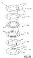
- Fig. 4a shows an exploded view of the six-turn transformer winding 21 of Fig. 3b.
- the vertical dashed lines in Fig. 4a indicate weld points between the respective turns 31a, 31b of the six-turn transformer winding 21. This embodiment reduces the number of layers 38 from six to four.
- Fig. 4b shows an exploded view of an eight-turn transformer winding 21 in accordance with the present invention.
- the vertical dashed lines in Fig. 4b again indicate weld points between the respective turns 31a, 31b of the eight-turn transformer winding 21.
- This embodiment reduces the number of layers 38 from eight to six.
- the present invention is not limited to the above described designs.
- Other designs which are possible are two-spiral, three-spiral, two-spiral/one-helix, three-spiral/one-helix, two-spiral/two-spiral, and four-spiral designs. These are described with references to Figs. 5a-c and 6a-c.
- Fig. 5a shows a cross sectional view of a hybrid two-spiral transformer winding in accordance with the present invention for use in the transformer 20.
- Fig. 5b shows a cross sectional view of a hybrid three-spiral transformer winding in accordance with the present invention for use in the transformer 20.
- Fig. 5c shows a cross sectional view of a hybrid two-spiral/one-helix transformer winding in accordance with the present invention for use in the transformer 20.
- Fig. 6a shows a cross sectional view of a hybrid three-spiral/one-helix transformer winding in accordance with the present invention for use in the transformer 20.
- Fig. 6b shows a cross sectional view of a hybrid two-spiral/two-spiral transformer winding in accordance with the present invention for use in the transformer 20.
- Fig. 6c shows a cross sectional view of a hybrid four-spiral transfomer winding in accordance with the present invention for use in the transformer 20.
- Figs. 5a-c and 6a-c represent different possible configurations of the spiral and helical turns 31a, 31b of the primary winding 21.
Landscapes
- Engineering & Computer Science (AREA)
- Power Engineering (AREA)
- Transportation (AREA)
- Mechanical Engineering (AREA)
- Computer Networks & Wireless Communication (AREA)
- Charge And Discharge Circuits For Batteries Or The Like (AREA)
- Coils Of Transformers For General Uses (AREA)
- Electric Propulsion And Braking For Vehicles (AREA)
Description
- The present invention relates to an inductive charging system for use in charging batteries of an electric vehicle, wherein said inductive charging system comprises a power source, a charge station coupled to the power source, a charge probe that comprises a primary core and a primary winding of a transformer coupled to the charge station by means of an extendable charging cable, a charge port disposed in the electric vehicle that comprises a secondary core and secondary windings of the transformer, and a charge controller coupled between the charge port and the batteries of the electric vehicle, wherein the primer winding comprises a predetermined number of turns stacked in a predetermined number of layers.
- Such an inductive charging system is known from the paper "An actively cooled 120 kW coaxial winding transformer for fast charging electric vehicles" by Klontz et al. in the Conference Record of the 1994 Industry Applications Conference 29th IAS Annual Meeting.
- The present invention relates generally to inductive battery charging systems, and more particularly, to the use of spiral/helical foil windings in an inductive charging probe that moves the outer foil windings of the probe closer to a heat sink, thereby improving thermal management.
- The assignee of the present invention designs, develops and manufactures inductive battery charging systems for use in charging the propulsion batteries of electric vehicles. The inductive charging system is employed to charge the propulsion batteries of an electric vehicle. A charge station is coupled to a power source and has an extendable charging cord that is coupled to a charge probe. The charge probe comprises a primary core and a primary winding of a transformer and is inserted into a charge port disposed in the electric vehicle that comprises secondary core and secondary windings of the transformer. The charge port and the charge probe form an inductive coupler. The charge port is coupled by way of a charge controller that interfaces to the propulsion batteries of the electric vehicle to supply power thereto.
- The closest prior art relating to the present invention is the use of a helical foil stack of windings in a planer transformer. The disadvantages of this type of transformer are that as the foil sack of windings grows in thickness, the losses in each foil windings increase because of the AC loss proximity effect.
- There is a desire to produce inductive chargers that permits inductive coupling at very high charge rates or power charging levels, such as on the order of 120 KW or more. However, it has been found that, at 50 KW power charging levels and higher, overheating at the interface between the inductive charger and electric vehicle becomes a limiting factor. Providing for improved thermal management of the inductive coupler is necessary to help overcome this limitation if the power transfer goal is to be met.
- Therefore, it is an objective of the present invention to provide for an inductive charging system that employs spiral/helical foil windings in an inductive charging probe that moves the outer foil windings of the probe closer to a heat sink, thereby improving the power handling capacity and thermal management of the system.
- The above and other objectives are met by an inductive charging system, mentioned at the outset, wherein at least one of the turns comprises a flat spiral multi-turn winding such that the number of layers is less than the number of turns.
- In order to meet the above and other objectives, the present invention is generally an inductive battery charging system that employs spiral/helical foil windings in an inductive charging probe that moves the outer foil windings of the probe closer to a heat sink. Use of the spiral/helical foil windings improves the power handling capacity and thermal management of the inducuve battery charging system.
- More specifically, the present invention may be employed in an inductive charging system for use in charging propulsion batteries of an electric vehicle. The inductive charging system comprises a power source and a charge station coupled to the power source. A charge probe that comprises a primary core and a primary winding of a transformer is coupled to the charge station by means of an extendable charging cable. A charge port is disposed in the electric vehicle that comprises a secondary core and secondary windings of the transformer. A charge controller is coupled between the charge port and the batteries of the electric vehicle for coupling power to the batteries. The improvement provided by the present invention comprises a primary winding having a predetermined number of turns stacked in a predetermined number of layers, wherein at least one of the turns comprises a spiral multi-turn winding such that the number of layers is less than the number of turns.
- Removing heat from transformer windings is difficult because the winding wires or foils are insulated. In the present invention, spiral/helical foil windings are used to move the outer foil conductors closer to the heat sink to improve thermal management and provide for higher power handling capacity. The present invention addresses the need to raise inductive power charging capacity of electric vehicle propulsion batteries to on the order of 120 KW and beyond.
- The various features and advantages of the present invention may be more readily understood with reference to the following detailed description taken in conjunction with the accompanying drawing, wherein like reference numerals designate like structural elements, and in which:
- Fig. 1a shows an electric vehicle inductive charging system employing novel spiral/helical foil windings in accordance with the principles of the present invention;
- Fig. 1b shows the primary components of the inductive charging system of Fig. 1a;
- Fig. 1c is an electrical diagrams corresponding to the components shown in the inductive charging system of Fig. 1b;
- Fig. 2 is a enlarged cross sectional view of the transformer of the inductive charging system of Figs. 1b and 1c employing the spiral/helical foil windings of the present invention;
- Fig 3a shows a conventional four-layer helical foil transformer winding;
- Fig. 3b shows a hybrid two-spiral/two-helix six-turn transformer winding in accordance with the present invention that replaces the conventional four-layer helical foil transformer winding of Fig. 3a;
- Fig. 4a shows an exploded view of the six-turn transformer winding of Fig 3b;
- Fig. 4b shows an exploded view of an eight-turn transformer winding in accordance with the present invention;
- Fig. 5a shows a cross sectional view of a two-spiral transformer winding for use in the six-turn transformer winding of Fig. 3b;
- Fig. 5b shows a cross sectional view of a three-spiral transformer winding for use in the six-turn transformer winding of Fig. 3b;
- Fig. 5c shows a cross sectional view of a two-spiral/one-helix transformer winding for use in the six-turn transformer winding of Fig. 3b;
- Fig. 6a shows a cross sectional view of a three-spiral/one-helix transformer winding for use in the eight-turn transformer of Fig. 4b;
- Fig. 6b shows a cross sectional view of a two-spiral/two-spiral transformer winding for use in the eight-turn transformer of Fig 4b; and
- Fig. 6c shows a cross sectional view of a four-spiral transformer winding for use in the eight-turn transformer of Fig. 4b.
-
- Referring to the drawing figure, Fig. 1a illustrates an electric vehicle
inductive charging system 10 employing an inductive charger 11 comprising employing novel spiral/helical foil windings in accordance with the principles of the present invention. Fig. 1a shows the interconnection of the inductive charger 11 to anelectric vehicle 12. Fig. 1c is an electrical diagram corresponding to the components shown in theinductive charging system 10 of Fig. 1b. Fig. 2 is a enlarged cross sectional view of atransformer 20 of theinductive charging system 10 of Figs. 1b and 1c employing spiral/helical foil windings in accordance with the principles of the present invention. - Referring to Figs. 1a-c and 2, a
charge station 13 is coupled to apower source 14 and has anextendable charging cable 15 that is coupled to acharge probe 16. Thecharge probe 16 comprises aprimary core 29 and a primary winding 21 of atransformer 20 and is inserted into acharge port 22 disposed in anelectric vehicle 12. Thecharge port 22 comprises asecondary core 33 andsecondary windings 23 of thetransformer 20. Thecharge port 22 and thecharge probe 16 form an inductive coupler. Thecharge port 22 is coupled by way of acharge controller 24 topropulsion batteries 25 of theelectric vehicle 12. - Low frequency AC provided by the
power source 14 is converted to medium frequency AC (75 KHZ) and then passed through the inductive coupler. The output of thesecondary windings 23 of the inductive coupler is rectified and filtered in thecharge controller 24 and is used to charge thepropulsion batteries 25 of theelectric vehicle 12. Fig. 1b shows the two portions of the inductive coupler, namely thecharge probe 16 and thecharge port 22. Thecharge probe 16 corresponds to theprimary core 29 and primary winding 21 of thetransformer 20 while thecharge port 22 contains thesecondary transformer cores 33, typically E-shaped cores, and thesecondary windings 23. - Fig. 1c shows a simplified electrical schematic of the interface between the charger 11 and the
electric vehicle 12. Fig. 1c shows that thecharge station 13 produces a 75 KHz output that is passed through a resonant tank circuit 26 andinductor 27 and is coupled to thecharge probe 16 which comprises the primary winding 21 of thetransformer 20. Thecharge port 22 comprises thesecondary windings 23 of thetransformer 20 and is coupled through arectifier 28 which produces a 375 volt signal at 300 amps which is coupled to thepropulsion batteries 25 of theelectric vehicle 12. - Referring to Fig. 2, the
probe 16 is comprised of theprimary core 29, the primary winding 21 which includes four-turns 31 (P1 to P4), and aprimary bladder 32 orheat sink 32. Theprobe 16 may use a 6/8 turn primary (P1 to P6/P8) and theprimary bladder 32 orheat sink 32. Thecharge port 22 is comprised of of two E-shapedsecondary cores 33, the secondary winding 23 comprising four turns 34 (S1 to S4), and upper and lowersecondary bladders turns windings transformer 20 are made from flat spiral or helical foil. Thebladders heat sinks 32 that are heat conducting and that are typically comprised of copper, for example, that are inserted between or adjacent to turns 31, 34 of thewindings windings transformer 20. - Fig. 3a shows a conventional four-layer helical foil transformer winding 21, such as is employed in a conventional primary winding 21 for use in the
transformer 20. The computed losses for this transformer winding 21 are 121.4 watts for an input current of 333 amps RMS at 75 KHz. - Fig. 3b shows a hybrid two-spiral/two-helix turn transformer winding 21 in accordance with the present invention for use in the
transformer 20 that replaces the conventional four-layer helical foil transformer winding 21 of Fig. 3a. The transformer winding 21 comprises two spiral turns 31a disposed in asingle layer 38a and twohelical turns 31b disposed in second and thirdstacked layers top foil turn 31b decrease by 1.5 W Also, the farthest outhybrid turn 31b of the winding 21 is disposed closer to thebladder 32, orheat sink 32, which makes thermal management easier. - Thus, as can be seen by means of a comparison of Figs. 3a and 3b, the improvement provided by the present invention comprises a primary winding 21 having a predetermined number of
turns 31 stacked in a predetermined number of layers 38, wherein at least one of theturns 31 comprises a spiral multi-turn winding 31a so that the number of layers 38 is less than the number ofturns 21. - Fig. 4a shows an exploded view of the six-turn transformer winding 21 of Fig. 3b. The vertical dashed lines in Fig. 4a indicate weld points between the
respective turns - Fig. 4b shows an exploded view of an eight-turn transformer winding 21 in accordance with the present invention. The vertical dashed lines in Fig. 4b again indicate weld points between the
respective turns - The present invention is not limited to the above described designs. Other designs which are possible are two-spiral, three-spiral, two-spiral/one-helix, three-spiral/one-helix, two-spiral/two-spiral, and four-spiral designs. These are described with references to Figs. 5a-c and 6a-c.
- Fig. 5a shows a cross sectional view of a hybrid two-spiral transformer winding in accordance with the present invention for use in the
transformer 20. Fig. 5b shows a cross sectional view of a hybrid three-spiral transformer winding in accordance with the present invention for use in thetransformer 20. Fig. 5c shows a cross sectional view of a hybrid two-spiral/one-helix transformer winding in accordance with the present invention for use in thetransformer 20. - Fig. 6a shows a cross sectional view of a hybrid three-spiral/one-helix transformer winding in accordance with the present invention for use in the
transformer 20. Fig. 6b shows a cross sectional view of a hybrid two-spiral/two-spiral transformer winding in accordance with the present invention for use in thetransformer 20. Fig. 6c shows a cross sectional view of a hybrid four-spiral transfomer winding in accordance with the present invention for use in thetransformer 20. - The various winding designs illustrated in Figs. 5a-c and 6a-c represent different possible configurations of the spiral and
helical turns - Thus, thee has been disclosed a new and improved inductive charging system that employs spiral/helical foil windings in an inductive charging probe that moves the outer foil windings of the probe closer to a heat sink, thereby improving the power handling capacity and thermal management of the system. It is to be understood that the above-described embodiment is merely illustrative of some of the many specific embodiments that represent applications of the principles of the present invention. Clearly, numerous and other arrangements can be readily devised by those skilled in the art without departing from the scope of the invention as defined by the appended claims.
Claims (3)
- An inductive charging system (10) for use in charging batteries (25) of an electric vehicle (12), wherein said inductive charging system (10) comprises a power source (14), a charge station (13) coupled to the power source (14), a charge probe (16) that comprises a primary core (29) and a primary winding (21) of a transformer (20) coupled to the charge station (13) by means of an extendable charging cable (15), a charge port (22) disposed in the electric vehicle (12) that comprises a secondary core (33) and secondary windings (23) of the transformer (20), and a charge controller (24) coupled between the charge port (22) and the batteries (25) of the electric vehicle (12), wherein the primary winding (21) comprises a predetermined number of turns (31) stacked in a predetermined number of layers (38), characterized in that:
at least one of the turns (31) of the primary winding (21) comprises a flat spiral multi-turn winding (31a) such that the number of layers (38) is less than the number of turns (31). - The system of claim 1, characterized in that the primary winding (21) comprises a first layer (38a) comprising two spiral turns (31a) that form the multi-turn winding and second and third layers (38b, 38c) each comprising helical turns (31b).
- The system of claim 1 or 2, characterized in that the charge probe (16) comprises a heat sink (32).
Applications Claiming Priority (2)
| Application Number | Priority Date | Filing Date | Title |
|---|---|---|---|
| US348665 | 1994-12-02 | ||
| US08/348,665 US5600222A (en) | 1993-10-25 | 1994-12-02 | Thermal management using a hybrid spiral/helical winding geometry |
Publications (2)
| Publication Number | Publication Date |
|---|---|
| EP0715392A1 EP0715392A1 (en) | 1996-06-05 |
| EP0715392B1 true EP0715392B1 (en) | 1999-09-15 |
Family
ID=23369013
Family Applications (1)
| Application Number | Title | Priority Date | Filing Date |
|---|---|---|---|
| EP95118969A Expired - Lifetime EP0715392B1 (en) | 1994-12-02 | 1995-12-01 | Thermal management using a hybrid spiral/helical winding geometry for inductive charger |
Country Status (5)
| Country | Link |
|---|---|
| US (1) | US5600222A (en) |
| EP (1) | EP0715392B1 (en) |
| JP (1) | JPH08280139A (en) |
| DE (1) | DE69512183T2 (en) |
| ES (1) | ES2135647T3 (en) |
Families Citing this family (37)
| Publication number | Priority date | Publication date | Assignee | Title |
|---|---|---|---|---|
| US5703462A (en) * | 1996-07-15 | 1997-12-30 | Delco Electronics Corp. | Inductive coupler assembly having its primary winding formed in a printed wiring board |
| IL120002A0 (en) * | 1997-01-13 | 1997-04-15 | Amt Ltd | Electrical coupler device |
| JPH11103531A (en) * | 1997-09-29 | 1999-04-13 | Nec Mori Energy Kk | Contactless charging device |
| US9425638B2 (en) | 1999-11-01 | 2016-08-23 | Anthony Sabo | Alignment independent and self-aligning inductive power transfer system |
| US6865080B2 (en) * | 2002-01-16 | 2005-03-08 | Rockwell Automation Technologies, Inc. | Compact fluid cooled power converter supporting multiple circuit boards |
| US7177153B2 (en) | 2002-01-16 | 2007-02-13 | Rockwell Automation Technologies, Inc. | Vehicle drive module having improved cooling configuration |
| US6965514B2 (en) | 2002-01-16 | 2005-11-15 | Rockwell Automation Technologies, Inc. | Fluid cooled vehicle drive module |
| US6972957B2 (en) * | 2002-01-16 | 2005-12-06 | Rockwell Automation Technologies, Inc. | Modular power converter having fluid cooled support |
| US7061775B2 (en) * | 2002-01-16 | 2006-06-13 | Rockwell Automation Technologies, Inc. | Power converter having improved EMI shielding |
| US6982873B2 (en) * | 2002-01-16 | 2006-01-03 | Rockwell Automation Technologies, Inc. | Compact vehicle drive module having improved thermal control |
| US7187568B2 (en) * | 2002-01-16 | 2007-03-06 | Rockwell Automation Technologies, Inc. | Power converter having improved terminal structure |
| US7032695B2 (en) * | 2002-01-16 | 2006-04-25 | Rockwell Automation Technologies, Inc. | Vehicle drive module having improved terminal design |
| US7187548B2 (en) * | 2002-01-16 | 2007-03-06 | Rockwell Automation Technologies, Inc. | Power converter having improved fluid cooling |
| US6909607B2 (en) * | 2002-01-16 | 2005-06-21 | Rockwell Automation Technologies, Inc. | Thermally matched fluid cooled power converter |
| US7142434B2 (en) * | 2002-01-16 | 2006-11-28 | Rockwell Automation Technologies, Inc. | Vehicle drive module having improved EMI shielding |
| US6898072B2 (en) * | 2002-01-16 | 2005-05-24 | Rockwell Automation Technologies, Inc. | Cooled electrical terminal assembly and device incorporating same |
| EP1547222B1 (en) * | 2002-06-10 | 2018-10-03 | City University of Hong Kong | Planar inductive battery charger |
| US8917057B2 (en) | 2002-06-10 | 2014-12-23 | City University Of Hong Kong | Battery charging system |
| US6960968B2 (en) * | 2002-06-26 | 2005-11-01 | Koninklijke Philips Electronics N.V. | Planar resonator for wireless power transfer |
| US7164584B2 (en) * | 2004-10-19 | 2007-01-16 | Honeywell International Inc. | Modular heatsink, electromagnetic device incorporating a modular heatsink and method of cooling an electromagnetic device using a modular heatsink |
| EP1699107B1 (en) | 2005-03-05 | 2017-05-31 | TRUMPF Hüttinger GmbH + Co. KG | 3 dB coupler |
| KR100792309B1 (en) * | 2006-02-06 | 2008-01-07 | 엘에스전선 주식회사 | Contactless charging system with heat dissipation means and charging unit thereof |
| US8307967B2 (en) * | 2007-07-04 | 2012-11-13 | Satyajit Patwardhan | Widely deployable charging system for vehicles |
| US20110221387A1 (en) * | 2010-03-09 | 2011-09-15 | Robert Louis Steigerwald | System and method for charging an energy storage system for an electric or hybrid-electric vehicle |
| US8841881B2 (en) | 2010-06-02 | 2014-09-23 | Bryan Marc Failing | Energy transfer with vehicles |
| EP2515410A1 (en) * | 2011-04-18 | 2012-10-24 | RRC power solutions GmbH | System, device and method for inductive energy transfer |
| WO2013142866A1 (en) | 2012-03-23 | 2013-09-26 | Hevo Inc. | Systems and mobile application for electric wireless charging stations |
| TW201407921A (en) * | 2012-08-03 | 2014-02-16 | 致伸科技股份有限公司 | Wireless charging transmission device |
| DE102012214199A1 (en) | 2012-08-09 | 2014-04-03 | Bayerische Motoren Werke Aktiengesellschaft | Device and method for positioning by triangulation |
| RU2534020C1 (en) * | 2013-06-19 | 2014-11-27 | Корпорация "САМСУНГ ЭЛЕКТРОНИКС Ко., Лтд." | Wireless charging system for mobile devices |
| US10369894B2 (en) | 2016-10-21 | 2019-08-06 | Hevo, Inc. | Parking alignment sequence for wirelessly charging an electric vehicle |
| US10128697B1 (en) | 2017-05-01 | 2018-11-13 | Hevo, Inc. | Detecting and deterring foreign objects and living objects at wireless charging stations |
| WO2019189760A1 (en) * | 2018-03-30 | 2019-10-03 | 大日本印刷株式会社 | Coil and coil pair, power transmission device and power receiving device, and power transmission system |
| US11605496B2 (en) | 2018-04-09 | 2023-03-14 | Abb Schweiz Ag | Foil wound magnetic assemblies with thermally conductive tape and methods of assembling same |
| US11160144B2 (en) | 2018-11-21 | 2021-10-26 | Illinois Tool Works Inc. | Modular transformers and induction heating systems having modular transformers |
| DE102019209467A1 (en) * | 2019-06-28 | 2020-12-31 | Audi Ag | Charging connector for a charging station for the transmission of electrical energy and a charging system for this |
| EP3826038A1 (en) | 2019-11-20 | 2021-05-26 | EnerSys Delaware Inc. | Electrical transformer and method of manufacturing an electrical transformer |
Family Cites Families (7)
| Publication number | Priority date | Publication date | Assignee | Title |
|---|---|---|---|---|
| US4656412A (en) * | 1985-07-08 | 1987-04-07 | California Institute Of Technology | Ferroresonant flux coupled battery charger |
| JPH056829A (en) * | 1990-12-28 | 1993-01-14 | Tokin Corp | Thin transformer |
| EP0552737A1 (en) * | 1992-01-22 | 1993-07-28 | Hughes Aircraft Company | Weatherized curb-side charger |
| US5341281A (en) * | 1993-05-14 | 1994-08-23 | Allen-Bradley Company, Inc. | Harmonic compensator using low leakage reactance transformer |
| US5434493A (en) * | 1993-10-25 | 1995-07-18 | Hughes Aircraft Company | Fixed core inductive charger |
| US5463303A (en) * | 1993-11-02 | 1995-10-31 | Hughes Aircraft Company | Multilayer separate windings of inductive charge coupler for automobile battery charging transformer |
| US5545966A (en) * | 1994-04-29 | 1996-08-13 | Delco Electronics Corp. | Air/liquid cooled metallic turn for high frequency high power charging transformers |
-
1994
- 1994-12-02 US US08/348,665 patent/US5600222A/en not_active Expired - Fee Related
-
1995
- 1995-12-01 EP EP95118969A patent/EP0715392B1/en not_active Expired - Lifetime
- 1995-12-01 ES ES95118969T patent/ES2135647T3/en not_active Expired - Lifetime
- 1995-12-01 DE DE69512183T patent/DE69512183T2/en not_active Expired - Lifetime
- 1995-12-04 JP JP7315679A patent/JPH08280139A/en active Pending
Non-Patent Citations (1)
| Title |
|---|
| KLONTZ ET AL: "An actively cooled 120kW coaxial winding transformer for fast charging electric vehicles", CONFERENCE RECORD OF THE 1994 INDUSTRY APPLICATIONS CONFERENCE - 29TH IAS ANNUAL MEETING 2-5 OCTOBER 1994, 2 October 1994 (1994-10-02), DENVER, USA, pages 1049 - 1054 * |
Also Published As
| Publication number | Publication date |
|---|---|
| ES2135647T3 (en) | 1999-11-01 |
| DE69512183D1 (en) | 1999-10-21 |
| EP0715392A1 (en) | 1996-06-05 |
| JPH08280139A (en) | 1996-10-22 |
| US5600222A (en) | 1997-02-04 |
| DE69512183T2 (en) | 2000-04-27 |
Similar Documents
| Publication | Publication Date | Title |
|---|---|---|
| US5600222A (en) | Thermal management using a hybrid spiral/helical winding geometry | |
| US5594317A (en) | Inductive charger field shaping using nonmagnetic metallic conductors | |
| KR102744731B1 (en) | Resonant dc-dc voltage converter | |
| US8188708B2 (en) | Battery charger with high frequency transformer | |
| JP5646470B2 (en) | Non-contact power supply device | |
| US5341083A (en) | Contactless battery charging system | |
| Severns et al. | An ultra-compact transformer for a 100 W to 120 kW inductive coupler for electric vehicle battery charging | |
| EP0552738A1 (en) | Separable inductive coupler | |
| JP3253592B2 (en) | Transmission side coupler | |
| KR102004230B1 (en) | Wireless power supply and pickup coil for solid-state transformer of railway vehicle and module thereof | |
| Klontz et al. | An electric vehicle charging system with'universal'inductive interface | |
| KR102563445B1 (en) | Medium-to-large-capacity three-dimensional winding planar transformer and power conversion apparatus including the same | |
| Gould et al. | A comparative study of on-board bidirectional chargers for electric vehicles to support vehicle-to-grid power transfer | |
| CN115668412A (en) | Inductance type quick charger | |
| JP2022072731A (en) | Coil device, power transmission device and power receiving device, and power transmission system | |
| US20240283293A1 (en) | Wireless power transfer device comprising coil structure and power transfer circuit for wireless power transfer, and wireless power reception device | |
| US6100781A (en) | High leakage inductance transformer | |
| JP2022012461A (en) | Coil, power transmission device and power receiving device, and power transmission system | |
| JPS5874021A (en) | Voltage feeding device for electric load | |
| JPH0614447Y2 (en) | High frequency transformer for welding | |
| JPH1022131A (en) | High frequency transformer winding | |
| JP6780909B2 (en) | Non-contact power transmission circuit and non-contact power transmission device | |
| EP4682918A1 (en) | Planar transformer | |
| CN113330674A (en) | Design and optimization of high power density low voltage DC-DC converter for electric vehicles | |
| EP4621810A1 (en) | High-power telescope transformer |
Legal Events
| Date | Code | Title | Description |
|---|---|---|---|
| PUAI | Public reference made under article 153(3) epc to a published international application that has entered the european phase |
Free format text: ORIGINAL CODE: 0009012 |
|
| AK | Designated contracting states |
Kind code of ref document: A1 Designated state(s): BE CH DE DK ES FR GB GR IT LI NL SE |
|
| RBV | Designated contracting states (corrected) |
Designated state(s): BE CH DE DK ES FR GB GR IT LI NL SE |
|
| 17P | Request for examination filed |
Effective date: 19961126 |
|
| 17Q | First examination report despatched |
Effective date: 19980213 |
|
| RAP1 | Party data changed (applicant data changed or rights of an application transferred) |
Owner name: HE HOLDINGS, INC. |
|
| RAP1 | Party data changed (applicant data changed or rights of an application transferred) |
Owner name: HUGHES ELECTRONICS CORPORATION |
|
| GRAG | Despatch of communication of intention to grant |
Free format text: ORIGINAL CODE: EPIDOS AGRA |
|
| GRAG | Despatch of communication of intention to grant |
Free format text: ORIGINAL CODE: EPIDOS AGRA |
|
| GRAH | Despatch of communication of intention to grant a patent |
Free format text: ORIGINAL CODE: EPIDOS IGRA |
|
| GRAH | Despatch of communication of intention to grant a patent |
Free format text: ORIGINAL CODE: EPIDOS IGRA |
|
| GRAA | (expected) grant |
Free format text: ORIGINAL CODE: 0009210 |
|
| ITF | It: translation for a ep patent filed | ||
| RAP1 | Party data changed (applicant data changed or rights of an application transferred) |
Owner name: GENERAL MOTORS CORPORATION |
|
| AK | Designated contracting states |
Kind code of ref document: B1 Designated state(s): BE CH DE DK ES FR GB GR IT LI NL SE |
|
| PG25 | Lapsed in a contracting state [announced via postgrant information from national office to epo] |
Ref country code: SE Free format text: THE PATENT HAS BEEN ANNULLED BY A DECISION OF A NATIONAL AUTHORITY Effective date: 19990915 Ref country code: LI Free format text: LAPSE BECAUSE OF FAILURE TO SUBMIT A TRANSLATION OF THE DESCRIPTION OR TO PAY THE FEE WITHIN THE PRESCRIBED TIME-LIMIT Effective date: 19990915 Ref country code: GR Free format text: LAPSE BECAUSE OF NON-PAYMENT OF DUE FEES Effective date: 19990915 Ref country code: CH Free format text: LAPSE BECAUSE OF FAILURE TO SUBMIT A TRANSLATION OF THE DESCRIPTION OR TO PAY THE FEE WITHIN THE PRESCRIBED TIME-LIMIT Effective date: 19990915 Ref country code: BE Free format text: LAPSE BECAUSE OF FAILURE TO SUBMIT A TRANSLATION OF THE DESCRIPTION OR TO PAY THE FEE WITHIN THE PRESCRIBED TIME-LIMIT Effective date: 19990915 |
|
| REG | Reference to a national code |
Ref country code: CH Ref legal event code: EP |
|
| REF | Corresponds to: |
Ref document number: 69512183 Country of ref document: DE Date of ref document: 19991021 |
|
| ET | Fr: translation filed | ||
| REG | Reference to a national code |
Ref country code: ES Ref legal event code: FG2A Ref document number: 2135647 Country of ref document: ES Kind code of ref document: T3 |
|
| PG25 | Lapsed in a contracting state [announced via postgrant information from national office to epo] |
Ref country code: DK Free format text: LAPSE BECAUSE OF FAILURE TO SUBMIT A TRANSLATION OF THE DESCRIPTION OR TO PAY THE FEE WITHIN THE PRESCRIBED TIME-LIMIT Effective date: 19991215 |
|
| REG | Reference to a national code |
Ref country code: CH Ref legal event code: PL |
|
| PLBE | No opposition filed within time limit |
Free format text: ORIGINAL CODE: 0009261 |
|
| STAA | Information on the status of an ep patent application or granted ep patent |
Free format text: STATUS: NO OPPOSITION FILED WITHIN TIME LIMIT |
|
| 26N | No opposition filed | ||
| PGFP | Annual fee paid to national office [announced via postgrant information from national office to epo] |
Ref country code: NL Payment date: 20001231 Year of fee payment: 6 |
|
| REG | Reference to a national code |
Ref country code: GB Ref legal event code: IF02 |
|
| PG25 | Lapsed in a contracting state [announced via postgrant information from national office to epo] |
Ref country code: NL Free format text: LAPSE BECAUSE OF NON-PAYMENT OF DUE FEES Effective date: 20020701 |
|
| NLV4 | Nl: lapsed or anulled due to non-payment of the annual fee |
Effective date: 20020701 |
|
| PG25 | Lapsed in a contracting state [announced via postgrant information from national office to epo] |
Ref country code: IT Free format text: LAPSE BECAUSE OF NON-PAYMENT OF DUE FEES;WARNING: LAPSES OF ITALIAN PATENTS WITH EFFECTIVE DATE BEFORE 2007 MAY HAVE OCCURRED AT ANY TIME BEFORE 2007. THE CORRECT EFFECTIVE DATE MAY BE DIFFERENT FROM THE ONE RECORDED. Effective date: 20051201 |
|
| REG | Reference to a national code |
Ref country code: GB Ref legal event code: 732E Free format text: REGISTERED BETWEEN 20090226 AND 20090304 |
|
| REG | Reference to a national code |
Ref country code: GB Ref legal event code: 732E Free format text: REGISTERED BETWEEN 20090305 AND 20090311 |
|
| REG | Reference to a national code |
Ref country code: GB Ref legal event code: 732E Free format text: REGISTERED BETWEEN 20091105 AND 20091111 |
|
| REG | Reference to a national code |
Ref country code: FR Ref legal event code: TP Ref country code: FR Ref legal event code: CD |
|
| PGFP | Annual fee paid to national office [announced via postgrant information from national office to epo] |
Ref country code: GB Payment date: 20101201 Year of fee payment: 16 |
|
| REG | Reference to a national code |
Ref country code: ES Ref legal event code: PC2A Owner name: GM GLOBAL TECHNOLOGY OPERTATIONS, INC. Effective date: 20110429 |
|
| PGFP | Annual fee paid to national office [announced via postgrant information from national office to epo] |
Ref country code: DE Payment date: 20101124 Year of fee payment: 16 |
|
| REG | Reference to a national code |
Ref country code: DE Ref legal event code: R081 Ref document number: 69512183 Country of ref document: DE Owner name: GENERAL MOTORS LLC ( N. D. GES. D. STAATES DEL, US Free format text: FORMER OWNER: GENERAL MOTORS COMPANY, DETROIT, MICH., US Effective date: 20110428 Ref country code: DE Ref legal event code: R081 Ref document number: 69512183 Country of ref document: DE Owner name: GENERAL MOTORS LLC ( N. D. GES. D. STAATES DEL, US Free format text: FORMER OWNER: GENERAL MOTORS COMPANY, DETROIT, US Effective date: 20110428 |
|
| PGFP | Annual fee paid to national office [announced via postgrant information from national office to epo] |
Ref country code: FR Payment date: 20111219 Year of fee payment: 17 |
|
| PGFP | Annual fee paid to national office [announced via postgrant information from national office to epo] |
Ref country code: ES Payment date: 20120116 Year of fee payment: 17 |
|
| GBPC | Gb: european patent ceased through non-payment of renewal fee |
Effective date: 20121201 |
|
| REG | Reference to a national code |
Ref country code: FR Ref legal event code: ST Effective date: 20130830 |
|
| REG | Reference to a national code |
Ref country code: DE Ref legal event code: R119 Ref document number: 69512183 Country of ref document: DE Effective date: 20130702 |
|
| PG25 | Lapsed in a contracting state [announced via postgrant information from national office to epo] |
Ref country code: DE Free format text: LAPSE BECAUSE OF NON-PAYMENT OF DUE FEES Effective date: 20130702 |
|
| PG25 | Lapsed in a contracting state [announced via postgrant information from national office to epo] |
Ref country code: GB Free format text: LAPSE BECAUSE OF NON-PAYMENT OF DUE FEES Effective date: 20121201 Ref country code: FR Free format text: LAPSE BECAUSE OF NON-PAYMENT OF DUE FEES Effective date: 20130102 |
|
| REG | Reference to a national code |
Ref country code: ES Ref legal event code: FD2A Effective date: 20140307 |
|
| PG25 | Lapsed in a contracting state [announced via postgrant information from national office to epo] |
Ref country code: ES Free format text: LAPSE BECAUSE OF NON-PAYMENT OF DUE FEES Effective date: 20121202 |