EP0715389B1 - Contactless battery charging system with high voltage cable - Google Patents
Contactless battery charging system with high voltage cable Download PDFInfo
- Publication number
- EP0715389B1 EP0715389B1 EP95118966A EP95118966A EP0715389B1 EP 0715389 B1 EP0715389 B1 EP 0715389B1 EP 95118966 A EP95118966 A EP 95118966A EP 95118966 A EP95118966 A EP 95118966A EP 0715389 B1 EP0715389 B1 EP 0715389B1
- Authority
- EP
- European Patent Office
- Prior art keywords
- cable
- coupled
- power
- electric vehicle
- primary
- Prior art date
- Legal status (The legal status is an assumption and is not a legal conclusion. Google has not performed a legal analysis and makes no representation as to the accuracy of the status listed.)
- Expired - Lifetime
Links
Images
Classifications
-
- H—ELECTRICITY
- H01—ELECTRIC ELEMENTS
- H01F—MAGNETS; INDUCTANCES; TRANSFORMERS; SELECTION OF MATERIALS FOR THEIR MAGNETIC PROPERTIES
- H01F38/00—Adaptations of transformers or inductances for specific applications or functions
- H01F38/50—Transformers for galvanic isolation
-
- H—ELECTRICITY
- H02—GENERATION; CONVERSION OR DISTRIBUTION OF ELECTRIC POWER
- H02J—ELECTRIC POWER NETWORKS; CIRCUIT ARRANGEMENTS OR SYSTEMS FOR SUPPLYING OR DISTRIBUTING ELECTRIC POWER; SYSTEMS FOR STORING ELECTRIC ENERGY
- H02J50/00—Circuit arrangements or systems for wireless supply or distribution of electric power
- H02J50/10—Circuit arrangements or systems for wireless supply or distribution of electric power using inductive coupling
- H02J50/12—Circuit arrangements or systems for wireless supply or distribution of electric power using inductive coupling of the resonant type
-
- B—PERFORMING OPERATIONS; TRANSPORTING
- B60—VEHICLES IN GENERAL
- B60L—PROPULSION OF ELECTRICALLY-PROPELLED VEHICLES; SUPPLYING ELECTRIC POWER FOR AUXILIARY EQUIPMENT OF ELECTRICALLY-PROPELLED VEHICLES; ELECTRODYNAMIC BRAKE SYSTEMS FOR VEHICLES IN GENERAL; MAGNETIC SUSPENSION OR LEVITATION FOR VEHICLES; MONITORING OPERATING VARIABLES OF ELECTRICALLY-PROPELLED VEHICLES; ELECTRIC SAFETY DEVICES FOR ELECTRICALLY-PROPELLED VEHICLES
- B60L53/00—Methods of charging batteries, specially adapted for electric vehicles; Charging stations or on-board charging equipment therefor; Exchange of energy storage elements in electric vehicles
- B60L53/10—Methods of charging batteries, specially adapted for electric vehicles; Charging stations or on-board charging equipment therefor; Exchange of energy storage elements in electric vehicles characterised by the energy transfer between the charging station and the vehicle
- B60L53/12—Inductive energy transfer
- B60L53/122—Circuits or methods for driving the primary coil, e.g. supplying electric power to the coil
-
- H—ELECTRICITY
- H02—GENERATION; CONVERSION OR DISTRIBUTION OF ELECTRIC POWER
- H02J—ELECTRIC POWER NETWORKS; CIRCUIT ARRANGEMENTS OR SYSTEMS FOR SUPPLYING OR DISTRIBUTING ELECTRIC POWER; SYSTEMS FOR STORING ELECTRIC ENERGY
- H02J50/00—Circuit arrangements or systems for wireless supply or distribution of electric power
- H02J50/70—Circuit arrangements or systems for wireless supply or distribution of electric power involving the reduction of electric, magnetic or electromagnetic leakage fields
-
- B—PERFORMING OPERATIONS; TRANSPORTING
- B60—VEHICLES IN GENERAL
- B60L—PROPULSION OF ELECTRICALLY-PROPELLED VEHICLES; SUPPLYING ELECTRIC POWER FOR AUXILIARY EQUIPMENT OF ELECTRICALLY-PROPELLED VEHICLES; ELECTRODYNAMIC BRAKE SYSTEMS FOR VEHICLES IN GENERAL; MAGNETIC SUSPENSION OR LEVITATION FOR VEHICLES; MONITORING OPERATING VARIABLES OF ELECTRICALLY-PROPELLED VEHICLES; ELECTRIC SAFETY DEVICES FOR ELECTRICALLY-PROPELLED VEHICLES
- B60L2270/00—Problem solutions or means not otherwise provided for
- B60L2270/10—Emission reduction
- B60L2270/14—Emission reduction of noise
- B60L2270/147—Emission reduction of noise electro magnetic [EMI]
-
- H—ELECTRICITY
- H02—GENERATION; CONVERSION OR DISTRIBUTION OF ELECTRIC POWER
- H02J—ELECTRIC POWER NETWORKS; CIRCUIT ARRANGEMENTS OR SYSTEMS FOR SUPPLYING OR DISTRIBUTING ELECTRIC POWER; SYSTEMS FOR STORING ELECTRIC ENERGY
- H02J7/00—Circuit arrangements for charging or discharging batteries or for supplying loads from batteries
- H02J7/90—Regulation of charging or discharging current or voltage
- H02J7/933—Regulation of charging or discharging current or voltage the cycle being controlled or terminated in response to electric parameters
-
- Y—GENERAL TAGGING OF NEW TECHNOLOGICAL DEVELOPMENTS; GENERAL TAGGING OF CROSS-SECTIONAL TECHNOLOGIES SPANNING OVER SEVERAL SECTIONS OF THE IPC; TECHNICAL SUBJECTS COVERED BY FORMER USPC CROSS-REFERENCE ART COLLECTIONS [XRACs] AND DIGESTS
- Y02—TECHNOLOGIES OR APPLICATIONS FOR MITIGATION OR ADAPTATION AGAINST CLIMATE CHANGE
- Y02T—CLIMATE CHANGE MITIGATION TECHNOLOGIES RELATED TO TRANSPORTATION
- Y02T10/00—Road transport of goods or passengers
- Y02T10/60—Other road transportation technologies with climate change mitigation effect
- Y02T10/70—Energy storage systems for electromobility, e.g. batteries
-
- Y—GENERAL TAGGING OF NEW TECHNOLOGICAL DEVELOPMENTS; GENERAL TAGGING OF CROSS-SECTIONAL TECHNOLOGIES SPANNING OVER SEVERAL SECTIONS OF THE IPC; TECHNICAL SUBJECTS COVERED BY FORMER USPC CROSS-REFERENCE ART COLLECTIONS [XRACs] AND DIGESTS
- Y02—TECHNOLOGIES OR APPLICATIONS FOR MITIGATION OR ADAPTATION AGAINST CLIMATE CHANGE
- Y02T—CLIMATE CHANGE MITIGATION TECHNOLOGIES RELATED TO TRANSPORTATION
- Y02T10/00—Road transport of goods or passengers
- Y02T10/60—Other road transportation technologies with climate change mitigation effect
- Y02T10/7072—Electromobility specific charging systems or methods for batteries, ultracapacitors, supercapacitors or double-layer capacitors
-
- Y—GENERAL TAGGING OF NEW TECHNOLOGICAL DEVELOPMENTS; GENERAL TAGGING OF CROSS-SECTIONAL TECHNOLOGIES SPANNING OVER SEVERAL SECTIONS OF THE IPC; TECHNICAL SUBJECTS COVERED BY FORMER USPC CROSS-REFERENCE ART COLLECTIONS [XRACs] AND DIGESTS
- Y02—TECHNOLOGIES OR APPLICATIONS FOR MITIGATION OR ADAPTATION AGAINST CLIMATE CHANGE
- Y02T—CLIMATE CHANGE MITIGATION TECHNOLOGIES RELATED TO TRANSPORTATION
- Y02T90/00—Enabling technologies or technologies with a potential or indirect contribution to GHG emissions mitigation
- Y02T90/10—Technologies relating to charging of electric vehicles
- Y02T90/12—Electric charging stations
-
- Y—GENERAL TAGGING OF NEW TECHNOLOGICAL DEVELOPMENTS; GENERAL TAGGING OF CROSS-SECTIONAL TECHNOLOGIES SPANNING OVER SEVERAL SECTIONS OF THE IPC; TECHNICAL SUBJECTS COVERED BY FORMER USPC CROSS-REFERENCE ART COLLECTIONS [XRACs] AND DIGESTS
- Y02—TECHNOLOGIES OR APPLICATIONS FOR MITIGATION OR ADAPTATION AGAINST CLIMATE CHANGE
- Y02T—CLIMATE CHANGE MITIGATION TECHNOLOGIES RELATED TO TRANSPORTATION
- Y02T90/00—Enabling technologies or technologies with a potential or indirect contribution to GHG emissions mitigation
- Y02T90/10—Technologies relating to charging of electric vehicles
- Y02T90/14—Plug-in electric vehicles
Definitions
- the present invention relates to a cable system for use with a battery charging system that charges a battery of an electric vehicle, wherein the battery charging system includes a primary power converter that is coupled to a power source that is located external to the electric vehicle, and a secondary power converter disposed on the electric vehicle that is coupled to the battery of the electric vehicle, and wherein the primary and secondary power converters are connected by way of a power cable.
- Such a cable system is known from WO 94/09544.
- the present invention relates generally to battery charging systems, and more particularly, to a high voltage cable system for use with contactless battery charging systems.
- a charging system has a power source that is coupled by way of a primary converter which transfers power through a charge port transformer to a secondary converter.
- the primary converter drives a cable that is coupled to the secondary converter from a full transistor bridge primary converter through a series resonant tank.
- the voltage in the cable is limited to the voltage that powers the transistor bridge. If a coaxial cable is used, the cable return has large dv/dt. This generates a large amount of electromagnetic interference (EMI) which is difficult to shield.
- EMI electromagnetic interference
- the power cable is a coaxial power cable having a central conductor and a ground return
- an isolation transformer is provided, having a primary winding coupled to an output of the primary power converter and having a secondary winding coupled to the central conductor and to the ground return of the coaxial power cable.
- the present invention is a high voltage cable system for use with contactless battery charging systems that charge electric vehicles, and the like.
- the contactless battery charging system includes a high frequency primary power converter that is coupled to a power source and that is located external to the electric vehicle, and a secondary power converter, known as a charge port, located on the electric vehicle that is coupled a propulsion battery or batteries of the electric vehicle.
- the primary and secondary converters are connected by way of a power cable.
- an isolation transformer is added at the output of the high frequency primary converter that is coupled to a coaxial power cable. This transformer allows one of the two outputs of the high frequency primary power converter to be connected to ground potential.
- the use of the isolation transformer eliminates the disadvantages of conventional cable arrangements.
- the isolation transformer provides improved safety and reduces electromagnetic interference (EMI) when driving the coaxial power cable connected between output of the isolation transformer and the charge port transformer located on the electric vehicle to couple power to the secondary converter.
- EMI electromagnetic interference
- the use of the present isolation transformer also allows for the use of a stepped-up voltage level to be used in the primary converter. This reduces the amount of current in the cable when delivering power to the secondary converter in the electric vehicle. This allows a much higher charge power to be delivered to the electric vehicle using a reasonably sized cable.
- the high level voltage transferred through the cable is stepped down to the required battery charging voltage by increasing the number of primary turns in the transformer in the secondary converter or charge port.
- the present invention increases safety, reduces EMI, and reduces the cable size required to transfer a given amount of charge power to electric vehicles utilizing contactless battery charging systems such as are disclosed in U.S. Patent No. 5,157,319.
- the present invention may be used with electric vehicle battery recharging systems manufactured by the assignee of the present invention for use in charging electric vehicles.
- the contactless battery charging system 11 includes a primary power converter 14 that is coupled to a power source 19 (typically providing an output voltage on the order of 208 VAC) and that is located external to the electric vehicle 13.
- a secondary power converter 15, also referred to as a charge port 15, is disposed on the electric vehicle 13 and is coupled to the propulsion batteries 12 of the electric vehicle 13.
- the primary and secondary power converters 14, 15 are connected by way of a coaxial power cable 16 having a central conductor 17 and aground return 18.
- the primary power converter 14 is comprised of a filter capacitor 20, a transistor bridge 21 comprising four field effect transistors 22, for example, that is coupled by way of a series resonant tank circuit 23 comprising an inductor 24 and a capacitor 25 to a primary winding 31 of an isolation transformer 30 in accordance with the present invention.
- the isolation transformer 30 has a predetermined step up turns ratio to increase the voltage and lower the current in the coaxial power cable 16.
- One side of the secondary winding 32 of the isolation transformer 30 is coupled to a first end of the coaxial power cable 16.
- the other side of the secondary winding 32 of the isolation transformer 30 is connected to chassis ground 33 to ground the ground return 18 of the coaxial power cable 16.
- the secondary power converter 15 is comprised of a secondary transformer 26 that comprises the charge port 15 for the electric vehicle 13.
- a secondary winding 27 of the secondary transformer 26 is coupled by way of rectifiers 28 to the propulsion batteries 12 of the electric vehicle 13.
- the second end of the coaxial power cable 16 forms a charge probe 35 that comprises a primary winding 29 of the secondary transformer 26.
- the transistor bridge 21 produces a square wave power drive signal that is coupled through the series resonant tank circuit 23 to the primary winding 31 of the isolation transformer 30.
- the step up turns ratio of the isolation transformer 30 increases the voltage and lowers the current in the coaxial power cable 16 that couples the power drive signal to the secondary transformer 26 in the charge port 15.
- the secondary transformer 26 then steps down the voltage as required for charging the propulsion batteries 12.
- One side of the secondary winding 32 of the isolation transformer 30 is connected to chassis ground so that the ground return 18 of the coaxial power cable 16 is at ground potential. This ensures that the ground return 18 of the coaxial power cable 16 has no signal voltage to contribute to electromagnetic interference (EMI).
- EMI electromagnetic interference
- the present invention thus increases safety, reduces EMI, and reduces the size of the coaxial power cable 16 required to transfer a given amount of charge power to the electric vehicle 13 utilizing the contactless battery charging system 11.
Landscapes
- Engineering & Computer Science (AREA)
- Power Engineering (AREA)
- Computer Networks & Wireless Communication (AREA)
- Transportation (AREA)
- Mechanical Engineering (AREA)
- Physics & Mathematics (AREA)
- Electromagnetism (AREA)
- Charge And Discharge Circuits For Batteries Or The Like (AREA)
- Electric Propulsion And Braking For Vehicles (AREA)
- Secondary Cells (AREA)
Description
- The present invention relates to a cable system for use with a battery charging system that charges a battery of an electric vehicle, wherein the battery charging system includes a primary power converter that is coupled to a power source that is located external to the electric vehicle, and a secondary power converter disposed on the electric vehicle that is coupled to the battery of the electric vehicle, and wherein the primary and secondary power converters are connected by way of a power cable.
- Such a cable system is known from WO 94/09544.
- The present invention relates generally to battery charging systems, and more particularly, to a high voltage cable system for use with contactless battery charging systems.
- The prior art relating to the present invention is disclosed in U.S. Patent No. 5,157,319 entitled "Contactless Battery Charging Systems". In this patent a charging system has a power source that is coupled by way of a primary converter which transfers power through a charge port transformer to a secondary converter. The primary converter drives a cable that is coupled to the secondary converter from a full transistor bridge primary converter through a series resonant tank. The voltage in the cable is limited to the voltage that powers the transistor bridge. If a coaxial cable is used, the cable return has large dv/dt. This generates a large amount of electromagnetic interference (EMI) which is difficult to shield. The present invention eliminates these disadvantages.
- Therefore, it is an objective of the present invention to provide for a high voltage cable system for use with contactless battery charging systems that eliminates the disadvantages of conventional cabling arrangements.
- The above and other objections are met by a cable system, mentioned at the outset, wherein the power cable is a coaxial power cable having a central conductor and a ground return, and wherein an isolation transformer is provided, having a primary winding coupled to an output of the primary power converter and having a secondary winding coupled to the central conductor and to the ground return of the coaxial power cable.
- In general, the present invention is a high voltage cable system for use with contactless battery charging systems that charge electric vehicles, and the like. The contactless battery charging system includes a high frequency primary power converter that is coupled to a power source and that is located external to the electric vehicle, and a secondary power converter, known as a charge port, located on the electric vehicle that is coupled a propulsion battery or batteries of the electric vehicle. The primary and secondary converters are connected by way of a power cable.
- In accordance with the present invention, an isolation transformer is added at the output of the high frequency primary converter that is coupled to a coaxial power cable. This transformer allows one of the two outputs of the high frequency primary power converter to be connected to ground potential.
- The use of the isolation transformer eliminates the disadvantages of conventional cable arrangements. The isolation transformer provides improved safety and reduces electromagnetic interference (EMI) when driving the coaxial power cable connected between output of the isolation transformer and the charge port transformer located on the electric vehicle to couple power to the secondary converter.
- The use of the present isolation transformer also allows for the use of a stepped-up voltage level to be used in the primary converter. This reduces the amount of current in the cable when delivering power to the secondary converter in the electric vehicle. This allows a much higher charge power to be delivered to the electric vehicle using a reasonably sized cable. The high level voltage transferred through the cable is stepped down to the required battery charging voltage by increasing the number of primary turns in the transformer in the secondary converter or charge port.
- The present invention increases safety, reduces EMI, and reduces the cable size required to transfer a given amount of charge power to electric vehicles utilizing contactless battery charging systems such as are disclosed in U.S. Patent No. 5,157,319. The present invention may be used with electric vehicle battery recharging systems manufactured by the assignee of the present invention for use in charging electric vehicles.
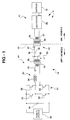
- The various features and advantages of the present invention may be more readily understood with reference to the following detailed description taken in conjunction with the accompanying drawing, wherein like reference numerals designate like structural elements, and in which the sole drawing illustrates a high voltage cable system in accordance with the principles of the present invention for use with contactless battery charging systems, and the like.
- Referring to the drawing figure, it illustrates a high
voltage cable system 10 for use with a contactlessbattery charging system 11 that charges apropulsion battery 12 orbatteries 12 of anelectric vehicle 13, for example. The contactlessbattery charging system 11 includes aprimary power converter 14 that is coupled to a power source 19 (typically providing an output voltage on the order of 208 VAC) and that is located external to theelectric vehicle 13. Asecondary power converter 15, also referred to as acharge port 15, is disposed on theelectric vehicle 13 and is coupled to thepropulsion batteries 12 of theelectric vehicle 13. The primary andsecondary power converters coaxial power cable 16 having acentral conductor 17 andaground return 18. - The
primary power converter 14 is comprised of afilter capacitor 20, atransistor bridge 21 comprising fourfield effect transistors 22, for example, that is coupled by way of a seriesresonant tank circuit 23 comprising aninductor 24 and acapacitor 25 to aprimary winding 31 of anisolation transformer 30 in accordance with the present invention. Theisolation transformer 30 has a predetermined step up turns ratio to increase the voltage and lower the current in thecoaxial power cable 16. One side of thesecondary winding 32 of theisolation transformer 30 is coupled to a first end of thecoaxial power cable 16. The other side of thesecondary winding 32 of theisolation transformer 30 is connected tochassis ground 33 to ground the ground return 18 of thecoaxial power cable 16. - The
secondary power converter 15 is comprised of asecondary transformer 26 that comprises thecharge port 15 for theelectric vehicle 13. Asecondary winding 27 of thesecondary transformer 26 is coupled by way ofrectifiers 28 to thepropulsion batteries 12 of theelectric vehicle 13. The second end of thecoaxial power cable 16 forms acharge probe 35 that comprises aprimary winding 29 of thesecondary transformer 26. - In operation, the
transistor bridge 21 produces a square wave power drive signal that is coupled through the seriesresonant tank circuit 23 to theprimary winding 31 of theisolation transformer 30. The step up turns ratio of theisolation transformer 30 increases the voltage and lowers the current in thecoaxial power cable 16 that couples the power drive signal to thesecondary transformer 26 in thecharge port 15. Thesecondary transformer 26 then steps down the voltage as required for charging thepropulsion batteries 12. One side of thesecondary winding 32 of theisolation transformer 30 is connected to chassis ground so that the ground return 18 of thecoaxial power cable 16 is at ground potential. This ensures that the ground return 18 of thecoaxial power cable 16 has no signal voltage to contribute to electromagnetic interference (EMI). The present invention thus increases safety, reduces EMI, and reduces the size of thecoaxial power cable 16 required to transfer a given amount of charge power to theelectric vehicle 13 utilizing the contactlessbattery charging system 11. - Thus there has been described a new and improved high voltage cable system for use with a contactless
battery charging system 10 that reduces electromagnetic interference, permits the use of an increased level charge power to be delivered to the electric vehicle using a reasonably sized cable, and reduces the amount of current in the cable when delivering power to the secondary converter in the electric vehicle. - It is to be understood that the above-described embodiment is merely illustrative of some of the many specific embodiments that represent applications of the principles of the present invention. Clearly, numerous and other arrangements can be readily devised by those skilled in the art without departing from the scope of the invention as defined by the appended claims.
Claims (3)
- A cable system (10) for use with a battery charging system (11) that charges a battery (12) of an electric vehicle (13), wherein the battery charging system (11) includes a primary power converter (14) that is coupled to a power source (19) that is located external to the electric vehicle (13), and a secondary power converter (15) disposed on the electric vehicle (13) that is coupled to the battery (12) of the electric vehicle (13), and wherein the primary and secondary power converters (14, 15) are connected by way of a power cable (17), characterized in that:the power cable (17) is a coaxial power cable (17) having a central conductor (17) and a ground return (18);an isolation transformer (30) having a primary winding (31) coupled to an output of the primary power converter (14) and having a secondary winding (32) coupled to the central conductor (17) and to the ground return (18) of the coaxial power cable (17).
- The cable system of claim 1, characterized in that the isolation transformer (30) has a predetermined step up turns ratio to increase the voltage and lower the current carried by the coaxial power cable (17).
- The cable system of claim 1 or 2, characterized in that the primary power converter (14) is comprised of a transistor bridge (21) that is coupled to a series resonant tank circuit (23), that the secondary power converter (15) is comprised of a secondary transformer (26) that is coupled by way of rectifiers (28) to the battery (12) of the electric vehicle (13), and that the isolation transformer (30) has its primary winding (31) coupled to the transistor bridge (21) of the primary power converter (14).
Applications Claiming Priority (2)
| Application Number | Priority Date | Filing Date | Title |
|---|---|---|---|
| US348663 | 1994-12-02 | ||
| US08/348,663 US5568036A (en) | 1994-12-02 | 1994-12-02 | Contactless battery charging system with high voltage cable |
Publications (2)
| Publication Number | Publication Date |
|---|---|
| EP0715389A1 EP0715389A1 (en) | 1996-06-05 |
| EP0715389B1 true EP0715389B1 (en) | 1999-03-31 |
Family
ID=23369004
Family Applications (1)
| Application Number | Title | Priority Date | Filing Date |
|---|---|---|---|
| EP95118966A Expired - Lifetime EP0715389B1 (en) | 1994-12-02 | 1995-12-01 | Contactless battery charging system with high voltage cable |
Country Status (6)
| Country | Link |
|---|---|
| US (1) | US5568036A (en) |
| EP (1) | EP0715389B1 (en) |
| JP (1) | JPH08293326A (en) |
| KR (1) | KR960027128A (en) |
| DE (1) | DE69508709T2 (en) |
| ES (1) | ES2131257T3 (en) |
Cited By (1)
| Publication number | Priority date | Publication date | Assignee | Title |
|---|---|---|---|---|
| CN103192742A (en) * | 2012-01-06 | 2013-07-10 | 李尔公司 | Control pilot frequency vehicle interface having non-local ground loop |
Families Citing this family (49)
| Publication number | Priority date | Publication date | Assignee | Title |
|---|---|---|---|---|
| US5684380A (en) * | 1996-07-26 | 1997-11-04 | Delco Electronics Corp. | Oil cooled high power inductive coupler |
| US5803215A (en) * | 1997-01-22 | 1998-09-08 | Schott Power Systems Incorporated | Method and apparatus for charging a plurality of electric vehicles |
| AU3046297A (en) | 1997-06-16 | 1999-01-04 | Yehuda Binder | Battery substitute pack |
| JPH1127870A (en) * | 1997-07-03 | 1999-01-29 | Toyota Autom Loom Works Ltd | Charge method, charging equipment, charger, and vehicle |
| US5959433A (en) * | 1997-08-22 | 1999-09-28 | Centurion Intl., Inc. | Universal inductive battery charger system |
| DE19836401A1 (en) * | 1997-09-19 | 2000-02-17 | Salcomp Oy Salo | Device for charging accumulators |
| US5926004A (en) * | 1997-10-10 | 1999-07-20 | Schott Power Systems Incorporated | Method and apparatus for charging one or more electric vehicles |
| JPH11178234A (en) * | 1997-12-10 | 1999-07-02 | Nissan Motor Co Ltd | Home power supply system using electric vehicles |
| US6104169A (en) * | 1999-08-19 | 2000-08-15 | General Motors Corporation | Battery charging system that controls charging power using fourth element capacitors |
| JP2002002335A (en) * | 2000-06-27 | 2002-01-09 | Shinko Electric Co Ltd | Non-contact power supply |
| GB2365304A (en) * | 2000-07-22 | 2002-02-13 | X Tek Systems Ltd | A compact X-ray source |
| JP3857508B2 (en) * | 2000-08-29 | 2006-12-13 | 株式会社日立製作所 | Elevator equipment |
| GB2388715B (en) * | 2002-05-13 | 2005-08-03 | Splashpower Ltd | Improvements relating to the transfer of electromagnetic power |
| US6906495B2 (en) * | 2002-05-13 | 2005-06-14 | Splashpower Limited | Contact-less power transfer |
| US6844702B2 (en) * | 2002-05-16 | 2005-01-18 | Koninklijke Philips Electronics N.V. | System, method and apparatus for contact-less battery charging with dynamic control |
| JP2005168167A (en) * | 2003-12-02 | 2005-06-23 | Honda Motor Co Ltd | DC-DC converter |
| JP4318174B2 (en) * | 2003-12-11 | 2009-08-19 | 本田技研工業株式会社 | DC-DC converter |
| KR100554889B1 (en) * | 2005-03-21 | 2006-03-03 | 주식회사 한림포스텍 | Contactless charging system |
| EP1864932A4 (en) * | 2005-04-01 | 2012-11-07 | Mitsubishi Electric Corp | POWER SUPPLY SYSTEM FOR ELEVATOR |
| US7548040B2 (en) * | 2005-07-28 | 2009-06-16 | Zerog Wireless, Inc. | Wireless battery charging of electronic devices such as wireless headsets/headphones |
| DE102006009312A1 (en) * | 2006-03-01 | 2007-09-06 | Jungheinrich Aktiengesellschaft | Industrial truck with a charger |
| US8228025B2 (en) * | 2007-11-09 | 2012-07-24 | City University Of Hong Kong | Electronic control method for a planar inductive battery charging apparatus |
| CA2729109A1 (en) | 2008-07-09 | 2010-01-14 | David W. Baarman | Wireless charging system |
| US8405346B2 (en) * | 2009-02-17 | 2013-03-26 | Diversified Power International, Llc | Inductively coupled power transfer assembly |
| US9397508B2 (en) * | 2009-05-22 | 2016-07-19 | Intersil Americas LLC | System and method for cell balancing and charging using a serially coupled inductor and capacitor |
| US8541980B2 (en) * | 2009-05-22 | 2013-09-24 | Intersil Americas LLC | System and method for cell balancing and charging |
| US8758323B2 (en) | 2009-07-30 | 2014-06-24 | Tandem Diabetes Care, Inc. | Infusion pump system with disposable cartridge having pressure venting and pressure feedback |
| US8174234B2 (en) * | 2009-10-08 | 2012-05-08 | Etymotic Research, Inc. | Magnetically coupled battery charging system |
| US8237402B2 (en) * | 2009-10-08 | 2012-08-07 | Etymotic Research, Inc. | Magnetically coupled battery charging system |
| US8174233B2 (en) * | 2009-10-08 | 2012-05-08 | Etymotic Research, Inc. | Magnetically coupled battery charging system |
| US8022775B2 (en) * | 2009-10-08 | 2011-09-20 | Etymotic Research, Inc. | Systems and methods for maintaining a drive signal to a resonant circuit at a resonant frequency |
| US8460816B2 (en) * | 2009-10-08 | 2013-06-11 | Etymotic Research, Inc. | Rechargeable battery assemblies and methods of constructing rechargeable battery assemblies |
| US10343535B2 (en) | 2010-04-08 | 2019-07-09 | Witricity Corporation | Wireless power antenna alignment adjustment system for vehicles |
| US9561730B2 (en) | 2010-04-08 | 2017-02-07 | Qualcomm Incorporated | Wireless power transmission in electric vehicles |
| US8841881B2 (en) | 2010-06-02 | 2014-09-23 | Bryan Marc Failing | Energy transfer with vehicles |
| EP2393181B1 (en) | 2010-06-02 | 2019-09-04 | FRIWO Gerätebau GmbH | Circuit for a system for a contactless, inductive energy transfer |
| FR2964266B1 (en) | 2010-09-01 | 2012-08-31 | Renault Sa | ELECTRIC MOTOR VEHICLE EQUIPPED WITH A CHARGER WITH OR WITHOUT CONTACT |
| US8749194B1 (en) | 2011-02-18 | 2014-06-10 | Vanguard Products Group, Inc. | Inductive charging retail display device |
| US20120244969A1 (en) | 2011-03-25 | 2012-09-27 | May Patents Ltd. | System and Method for a Motion Sensing Device |
| JP5732307B2 (en) * | 2011-04-22 | 2015-06-10 | 矢崎総業株式会社 | Resonant contactless power supply system |
| US9112373B2 (en) | 2012-01-06 | 2015-08-18 | Lear Corporation | Control pilot vehicle interface with non-local return to ground |
| WO2013121535A1 (en) * | 2012-02-15 | 2013-08-22 | パイオニア株式会社 | Non-contact power supply apparatus |
| FR2988232B1 (en) * | 2012-03-14 | 2015-01-16 | Renault Sa | CONTACTLESS RECHARGE DEVICE FOR MOTOR VEHICLE BATTERY AND METHOD OF CONTROLLING THE SAME |
| CN104104234A (en) * | 2013-04-07 | 2014-10-15 | 华云逸力(北京)光纤传感技术有限公司 | Secondary power supply technology under high-voltage environment based on electromagnetic theory |
| CN109687595B (en) * | 2013-05-09 | 2022-01-14 | 泰科电子(上海)有限公司 | Non-contact power supply circuit |
| CN103956618A (en) * | 2014-05-13 | 2014-07-30 | 安徽中家智锐科技有限公司 | Non-contact type safety socket in direct current power distribution network |
| RU179239U1 (en) * | 2017-11-17 | 2018-05-07 | Публичное акционерное общество "Межрегиональная распределительная сетевая компания Центра" (ПАО "МРСК Центра") | CURRENT POWER TAKE-OFF DEVICE |
| CN108023384A (en) * | 2017-12-26 | 2018-05-11 | 深圳市恒浩伟业科技有限公司 | Car emergency startup power supply |
| US11420524B2 (en) | 2019-12-20 | 2022-08-23 | Ut-Battelle, Llc | Wireless power system |
Family Cites Families (11)
| Publication number | Priority date | Publication date | Assignee | Title |
|---|---|---|---|---|
| US2708719A (en) * | 1949-02-17 | 1955-05-17 | Nat Cylinder Gas Co | High frequency generator |
| DE3305224A1 (en) * | 1983-02-16 | 1984-08-16 | Bbc Brown Boveri & Cie | ON-BOARD BATTERY CHARGER |
| DE3818150A1 (en) * | 1988-05-28 | 1989-11-30 | Blaupunkt Werke Gmbh | CIRCUIT ARRANGEMENT FOR COMPENSATING INTERFERENCE |
| US5157319A (en) * | 1991-09-27 | 1992-10-20 | Electric Power Research Institute | Contactless battery charging system |
| US5341083A (en) * | 1991-09-27 | 1994-08-23 | Electric Power Research Institute, Inc. | Contactless battery charging system |
| US5301096A (en) * | 1991-09-27 | 1994-04-05 | Electric Power Research Institute | Submersible contactless power delivery system |
| US5216402A (en) * | 1992-01-22 | 1993-06-01 | Hughes Aircraft Company | Separable inductive coupler |
| US5327065A (en) * | 1992-01-22 | 1994-07-05 | Hughes Aircraft Company | Hand-held inductive charger having concentric windings |
| US5323099A (en) * | 1992-01-22 | 1994-06-21 | Hughes Aircraft Company | Wall/ceiling mounted inductive charger |
| EP0552737A1 (en) * | 1992-01-22 | 1993-07-28 | Hughes Aircraft Company | Weatherized curb-side charger |
| US5341281A (en) * | 1993-05-14 | 1994-08-23 | Allen-Bradley Company, Inc. | Harmonic compensator using low leakage reactance transformer |
-
1994
- 1994-12-02 US US08/348,663 patent/US5568036A/en not_active Expired - Lifetime
-
1995
- 1995-12-01 ES ES95118966T patent/ES2131257T3/en not_active Expired - Lifetime
- 1995-12-01 EP EP95118966A patent/EP0715389B1/en not_active Expired - Lifetime
- 1995-12-01 DE DE69508709T patent/DE69508709T2/en not_active Expired - Fee Related
- 1995-12-02 KR KR1019950046217A patent/KR960027128A/en not_active Withdrawn
- 1995-12-04 JP JP7315676A patent/JPH08293326A/en active Pending
Cited By (2)
| Publication number | Priority date | Publication date | Assignee | Title |
|---|---|---|---|---|
| CN103192742A (en) * | 2012-01-06 | 2013-07-10 | 李尔公司 | Control pilot frequency vehicle interface having non-local ground loop |
| CN103192742B (en) * | 2012-01-06 | 2015-09-09 | 李尔公司 | There is the control pilot tone vehicle interface of non-local circuit ground |
Also Published As
| Publication number | Publication date |
|---|---|
| DE69508709T2 (en) | 1999-07-29 |
| ES2131257T3 (en) | 1999-07-16 |
| US5568036A (en) | 1996-10-22 |
| JPH08293326A (en) | 1996-11-05 |
| EP0715389A1 (en) | 1996-06-05 |
| DE69508709D1 (en) | 1999-05-06 |
| KR960027128A (en) | 1996-07-22 |
Similar Documents
| Publication | Publication Date | Title |
|---|---|---|
| US5568036A (en) | Contactless battery charging system with high voltage cable | |
| KR102692322B1 (en) | united converter apparatus | |
| DE69827733T2 (en) | Battery charger in a mobile electrical unit | |
| US5926004A (en) | Method and apparatus for charging one or more electric vehicles | |
| US6087802A (en) | Lightweight, compact, on-board electric vehicle battery charger | |
| EP0764359B1 (en) | Improved emi filter topology for power inverters | |
| US5600222A (en) | Thermal management using a hybrid spiral/helical winding geometry | |
| US4922396A (en) | DC-DC converter | |
| CA2097787A1 (en) | Electric system for an electric vehicle | |
| Al-Saadi et al. | Capacitive Power Transfer for Wireless Batteries Charging. | |
| US20210300192A1 (en) | Wired/wireless integrated power reception system | |
| EP0398723A2 (en) | Switching power supply apparatus and isolating method thereof | |
| US4807105A (en) | Circuit arrangement for producing high DC voltage from medium-frequency AC voltage | |
| US20210399570A1 (en) | Electric vehicle DC charging system using a voltage of 1250 volts output by a transformer | |
| US20240006908A1 (en) | Apparatus and/or system for providing pulsating buffer converter with a boost circuit | |
| EP0064483B1 (en) | High voltage converter | |
| JPH11235024A (en) | Inverter device | |
| Tomar et al. | An efficient bi-directional dc/dc charger for electric vehicle battery charging | |
| DE102024123094A1 (en) | CHARGING DEVICE AND ELECTRIC VEHICLE | |
| US6104169A (en) | Battery charging system that controls charging power using fourth element capacitors | |
| KR20160046416A (en) | Noise compensation circuit | |
| DE102011089989A1 (en) | Arrangement for charging battery of car, in garage, has reception unit connected with inputs of charging unit over output of reception unit, where one of inputs of charging unit is connected with intermediate circuit capacitor | |
| JPH0731075A (en) | Charger | |
| JPH0823673A (en) | Switching power supply device and insulation method thereof | |
| JP2607736B2 (en) | Automotive microwave oven |
Legal Events
| Date | Code | Title | Description |
|---|---|---|---|
| PUAI | Public reference made under article 153(3) epc to a published international application that has entered the european phase |
Free format text: ORIGINAL CODE: 0009012 |
|
| AK | Designated contracting states |
Kind code of ref document: A1 Designated state(s): BE CH DE DK ES FR GB GR IT LI NL SE |
|
| RBV | Designated contracting states (corrected) |
Designated state(s): BE CH DE DK ES FR GB GR IT LI NL SE |
|
| 17P | Request for examination filed |
Effective date: 19961110 |
|
| GRAG | Despatch of communication of intention to grant |
Free format text: ORIGINAL CODE: EPIDOS AGRA |
|
| GRAG | Despatch of communication of intention to grant |
Free format text: ORIGINAL CODE: EPIDOS AGRA |
|
| GRAH | Despatch of communication of intention to grant a patent |
Free format text: ORIGINAL CODE: EPIDOS IGRA |
|
| 17Q | First examination report despatched |
Effective date: 19980313 |
|
| GRAH | Despatch of communication of intention to grant a patent |
Free format text: ORIGINAL CODE: EPIDOS IGRA |
|
| RAP1 | Party data changed (applicant data changed or rights of an application transferred) |
Owner name: HE HOLDINGS, INC. |
|
| RAP1 | Party data changed (applicant data changed or rights of an application transferred) |
Owner name: HUGHES ELECTRONICS CORPORATION |
|
| GRAA | (expected) grant |
Free format text: ORIGINAL CODE: 0009210 |
|
| AK | Designated contracting states |
Kind code of ref document: B1 Designated state(s): BE CH DE DK ES FR GB GR IT LI NL SE |
|
| PG25 | Lapsed in a contracting state [announced via postgrant information from national office to epo] |
Ref country code: SE Free format text: THE PATENT HAS BEEN ANNULLED BY A DECISION OF A NATIONAL AUTHORITY Effective date: 19990331 Ref country code: LI Free format text: LAPSE BECAUSE OF FAILURE TO SUBMIT A TRANSLATION OF THE DESCRIPTION OR TO PAY THE FEE WITHIN THE PRESCRIBED TIME-LIMIT Effective date: 19990331 Ref country code: GR Free format text: LAPSE BECAUSE OF NON-PAYMENT OF DUE FEES Effective date: 19990331 Ref country code: CH Free format text: LAPSE BECAUSE OF FAILURE TO SUBMIT A TRANSLATION OF THE DESCRIPTION OR TO PAY THE FEE WITHIN THE PRESCRIBED TIME-LIMIT Effective date: 19990331 Ref country code: BE Free format text: LAPSE BECAUSE OF FAILURE TO SUBMIT A TRANSLATION OF THE DESCRIPTION OR TO PAY THE FEE WITHIN THE PRESCRIBED TIME-LIMIT Effective date: 19990331 |
|
| REG | Reference to a national code |
Ref country code: CH Ref legal event code: EP |
|
| REF | Corresponds to: |
Ref document number: 69508709 Country of ref document: DE Date of ref document: 19990506 |
|
| ET | Fr: translation filed | ||
| RAP2 | Party data changed (patent owner data changed or rights of a patent transferred) |
Owner name: GENERAL MOTORS CORPORATION |
|
| PG25 | Lapsed in a contracting state [announced via postgrant information from national office to epo] |
Ref country code: DK Free format text: LAPSE BECAUSE OF FAILURE TO SUBMIT A TRANSLATION OF THE DESCRIPTION OR TO PAY THE FEE WITHIN THE PRESCRIBED TIME-LIMIT Effective date: 19990630 |
|
| REG | Reference to a national code |
Ref country code: ES Ref legal event code: FG2A Ref document number: 2131257 Country of ref document: ES Kind code of ref document: T3 |
|
| NLT2 | Nl: modifications (of names), taken from the european patent patent bulletin |
Owner name: GENERAL MOTORS CORPORATION |
|
| REG | Reference to a national code |
Ref country code: CH Ref legal event code: PL |
|
| NLXE | Nl: other communications concerning ep-patents (part 3 heading xe) |
Free format text: PAT. BUL. 07/99 PAGE 948: CORR.: GENERAL MOTORS CORPORATION. |
|
| PGFP | Annual fee paid to national office [announced via postgrant information from national office to epo] |
Ref country code: GB Payment date: 19991201 Year of fee payment: 5 Ref country code: FR Payment date: 19991201 Year of fee payment: 5 |
|
| PGFP | Annual fee paid to national office [announced via postgrant information from national office to epo] |
Ref country code: ES Payment date: 19991203 Year of fee payment: 5 |
|
| PGFP | Annual fee paid to national office [announced via postgrant information from national office to epo] |
Ref country code: DE Payment date: 19991222 Year of fee payment: 5 |
|
| PGFP | Annual fee paid to national office [announced via postgrant information from national office to epo] |
Ref country code: NL Payment date: 19991231 Year of fee payment: 5 |
|
| PLBE | No opposition filed within time limit |
Free format text: ORIGINAL CODE: 0009261 |
|
| STAA | Information on the status of an ep patent application or granted ep patent |
Free format text: STATUS: NO OPPOSITION FILED WITHIN TIME LIMIT |
|
| 26N | No opposition filed | ||
| PG25 | Lapsed in a contracting state [announced via postgrant information from national office to epo] |
Ref country code: GB Free format text: LAPSE BECAUSE OF NON-PAYMENT OF DUE FEES Effective date: 20001201 |
|
| PG25 | Lapsed in a contracting state [announced via postgrant information from national office to epo] |
Ref country code: NL Free format text: LAPSE BECAUSE OF NON-PAYMENT OF DUE FEES Effective date: 20010701 |
|
| GBPC | Gb: european patent ceased through non-payment of renewal fee |
Effective date: 20001201 |
|
| PG25 | Lapsed in a contracting state [announced via postgrant information from national office to epo] |
Ref country code: FR Free format text: LAPSE BECAUSE OF NON-PAYMENT OF DUE FEES Effective date: 20010831 |
|
| NLV4 | Nl: lapsed or anulled due to non-payment of the annual fee |
Effective date: 20010701 |
|
| REG | Reference to a national code |
Ref country code: FR Ref legal event code: ST |
|
| PG25 | Lapsed in a contracting state [announced via postgrant information from national office to epo] |
Ref country code: DE Free format text: LAPSE BECAUSE OF NON-PAYMENT OF DUE FEES Effective date: 20011002 |
|
| PG25 | Lapsed in a contracting state [announced via postgrant information from national office to epo] |
Ref country code: ES Free format text: LAPSE BECAUSE OF NON-PAYMENT OF DUE FEES Effective date: 20011202 |
|
| REG | Reference to a national code |
Ref country code: ES Ref legal event code: FD2A Effective date: 20020112 |
|
| PG25 | Lapsed in a contracting state [announced via postgrant information from national office to epo] |
Ref country code: IT Free format text: LAPSE BECAUSE OF NON-PAYMENT OF DUE FEES;WARNING: LAPSES OF ITALIAN PATENTS WITH EFFECTIVE DATE BEFORE 2007 MAY HAVE OCCURRED AT ANY TIME BEFORE 2007. THE CORRECT EFFECTIVE DATE MAY BE DIFFERENT FROM THE ONE RECORDED. Effective date: 20051201 |