EP0715158A2 - Electrochemical force and pressure sensor - Google Patents
Electrochemical force and pressure sensor Download PDFInfo
- Publication number
- EP0715158A2 EP0715158A2 EP96101243A EP96101243A EP0715158A2 EP 0715158 A2 EP0715158 A2 EP 0715158A2 EP 96101243 A EP96101243 A EP 96101243A EP 96101243 A EP96101243 A EP 96101243A EP 0715158 A2 EP0715158 A2 EP 0715158A2
- Authority
- EP
- European Patent Office
- Prior art keywords
- sensor
- pressure
- electrode pair
- gas
- chamber
- Prior art date
- Legal status (The legal status is an assumption and is not a legal conclusion. Google has not performed a legal analysis and makes no representation as to the accuracy of the status listed.)
- Withdrawn
Links
Images


Classifications
-
- G—PHYSICS
- G01—MEASURING; TESTING
- G01L—MEASURING FORCE, STRESS, TORQUE, WORK, MECHANICAL POWER, MECHANICAL EFFICIENCY, OR FLUID PRESSURE
- G01L1/00—Measuring force or stress, in general
- G01L1/20—Measuring force or stress, in general by measuring variations in ohmic resistance of solid materials or of electrically-conductive fluids; by making use of electrokinetic cells, i.e. liquid-containing cells wherein an electrical potential is produced or varied upon the application of stress
-
- G—PHYSICS
- G01—MEASURING; TESTING
- G01L—MEASURING FORCE, STRESS, TORQUE, WORK, MECHANICAL POWER, MECHANICAL EFFICIENCY, OR FLUID PRESSURE
- G01L9/00—Measuring steady of quasi-steady pressure of fluid or fluent solid material by electric or magnetic pressure-sensitive elements; Transmitting or indicating the displacement of mechanical pressure-sensitive elements, used to measure the steady or quasi-steady pressure of a fluid or fluent solid material, by electric or magnetic means
- G01L9/18—Measuring steady of quasi-steady pressure of fluid or fluent solid material by electric or magnetic pressure-sensitive elements; Transmitting or indicating the displacement of mechanical pressure-sensitive elements, used to measure the steady or quasi-steady pressure of a fluid or fluent solid material, by electric or magnetic means by making use of electrokinetic cells, i.e. liquid-containing cells wherein an electric potential is produced or varied upon the application of stress
Definitions
- This invention involves generally devices for sensing and effecting force and pressure and more particularly involves a pressure transducer that reversibly converts mechanical force or pressure into an electrical voltage by means of an electrochemical process.
- the piezoelectric transducer uses a crystalline material that produces an output voltage proportional to the rate of change in strain over time. Because the output voltage is generated only under dynamic conditions, the piezoelectric device cannot be used for static or steady-state pressure or force measurements. It is normally used as a miniature instrument intended to measure vibration or dynamic pressure.
- the vibrating-wire transducer comprises a fine wire supported so that its tension and strain varies according to the applied pressure or force. When this wire lies between the poles of a permanent magnet, it vibrates at its natural frequency upon application of an oscillating voltage.
- the vibrating-wire transducer output is an oscillating voltage that changes in frequency according to changes in the wire tension induced by the applied pressure or force.
- Each of these transducer principles requires a displacement to generate a voltage output from the sensor.
- Pressure measurements are achieved by summing applied pressure over a flexible material that in turn is permitted limited travel.
- the flexible member may be a diaphragm, capsule, bellows or several variations of bourdon tubes. Each of these provides a limited displacement under applied pressure.
- Absolute pressures are generally determined by sealing either the capsule or bellows assembly, or the instrument chamber, at a reference pressure usually close to zero.
- Gauge pressure relative to ambient atmospheric pressure
- Differential pressure can be measured by permitting the two pressures in question access to opposite sides of the sensing member.
- each of the above-mentioned transduction techniques is subject to several limitations. Except for the piezoelectric transducer, all such methods require a separate voltage source. The piezoelectric transducer requires no separate voltage source, but it is not useful for static pressure measurement. Again except for the piezoelectric transducer, none of the above transduction techniques are amenable to self-calibration. Although a piezoelectric transducer can be self-calibrated by means of the reciprocity principle, this method is useful only for dynamic (sinusoidally-varying) pressures. A simple, self-calibrating pressure sensor that can be calibrated to accurately sense the absolute value of static pressure without reference to a calibration standard is unknown in the art.
- An electrochemical cell is typically formed by positioning an electrolytic membrane between and in contact with a cathode and an anode.
- a cell can either generate electricity (as a fuel cell) or do mechanical work (as a motor), it has not heretofore been used as a transducer for the sensing or effecting of force and pressure.
- a fuel gas such as hydrogen is supplied to the anode and a gaseous oxidant such as oxygen is supplied to the cathode, as disclosed by Wentworth in U.S. Patent 3,418,168.
- a force sensor comprising:
- the invention also includes a force sensor/effector comprising the force sensor described in relation to said first aspect and further comprising:
- a method for determining the pressure of an electrochemically active gas in a storage chamber and a sensor chamber of an electrochemical fluid pressure sensor having an electrolytic membrane with at least one electrode pair comprising the steps of:
- a method for calibrating a dual-chamber electrochemical pressure sensor having an electrolytic membrane with at least one electrode pair and a rigid wall disposed in contact with the flexible wall of the sensor chamber the chambers containing an electrochemically active gas, comprising the steps of:
- the present invention offers several advantages over the related art.
- the electrochemical transduction phenomenon is reversible, which means that the present invention is well-suited for both sensing and applying or effecting a force.
- the precision of the electrochemical force sensor/effector exceeds 0.05% without special provision for internal calibration because of the nature of the transduction phenomenon.
- the dual-chamber embodiment of the electrochemical pressure sensor can be self-calibrated merely by first measuring the output voltage, applying a known direct current for a known period of time, and remeasuring the output voltage. Using a simple algebraic relationship, the absolute pressure of the electrochemical gas on both sides of the electrolytic membrane can be calculated with an accuracy and precision limited only by the electrical voltage and current measurement means.
- the applicable formula can be understood from an examination of the electrochemical transduction phenomenon, wherein the current flow through the electrolytic membrane is equal to the number of ions transported across the membrane per unit time.
- the gas pressure ratio across the electrolytic membrane is also related to the number of ions (gas molecules) transported across the membrane, an exact relationship exists between membrane current and membrane pressure ratio. That is, the number of electrons flowing is precisely related to the number of gas molecules transported, except for diffusion losses induced by the pressure differential across the electrolytic membrane.
- Simple control means for applying a bias current to the electrolytic membrane in response to the sensor voltage output will compensate for diffusion losses. That is, a counter-diffusion gas flow can be automatically induced by a controller in response to a diffusion estimate computed for the measured pressure differential.
- Yet another advantage of the present invention arising from the reversibility of the electrochemical transduction phenomenon is the capacity for effecting a desired force using the same sensing device.
- This has application to the robotic arts for use in a mechanical gripper or manipulator.
- Most contact sensors are passive. Mechanical effectors require considerable feedback and computation to allow a manipulator to react to contact forces.
- the present invention permits an embodiment that can sense and react to contact forces with simple local control means involving simple feedback of sensor output voltage to a means for applying current to the electrolytic membrane. The force applied by the effector/sensor responds immediately and precisely to the applied current.
- the present invention is uniquely suited to the measurement of partial-pressure of selected electrochemically active gases such as hydrogen, oxygen, and the halogens.
- the electrolytic membrane output voltage will always be directly related to the ratio of partial-pressures across the electrolytic membrane and not to the ratio of gas mixture pressures.
- Another advantage of the present invention is its suitability for miniaturization.
- the output voltage from the electrolytic membrane is not related to the membrane area.
- membranes with areas of less than 2 mm 2 can function effectively as pressure sensors for use within catheters for measurement of internal blood and tissues pressures.
- the typical pressure sensor transducer known in the art relies on some physical displacement to generate the transducer output signal, these sensors often comprise a number of moving parts, thereby limiting the practicality of miniaturization.
- the present invention offers the additional advantages of high efficiency, low power requirements, and flexible geometry. All of these advantages together with the absence of moving parts (other than a flexing bellows or diaphragm) result in a low production cost for the preferred embodiments of the present invention.
- An integrated sensor/effector embodiment includes an additional micro-controller for the electrochemical cell drive current and is responsive to the electrochemical cell output voltage (sensed pressure) and a remote robotics-controller signal that establishes the desired contact.
- This local micro-controller responds to the sensed force by changing the drive current and thereby the gas pressure under the diaphragm or bellows.
- the locally-controlled pressure change constitutes a physical contact interaction with the external environment useful for robotic mechanical manipulators.
- the present invention is also ideally suited for application as an internal pressure sensor in an electrochemical motor as disclosed in copending application 07/563,050 by the inventor, entitled “Efficient Electrochemical Motor,” filed concurrently herewith.
- Three illustrated embodiments of the present invention are of primary interest as pressure and force sensors and effectors.
- Figure 1 illustrates a dual-chamber pressure sensor 10 showing a reference chamber 12 and a sensing chamber 14 separated by a rigidly-supported electrolytic membrane 16 having pervious conductors 18 and 20 on either side of membrane 16 and rigid supporting printed-circuit boards (PCB's) 17 and 19 on either side of the electrode/ionomer assembly.
- Sensing chamber 14 comprises a flexible diaphragm 22 which deforms under the external measured pressure, until the pressure within sensing chamber 14 is equal to the external measured pressure.
- Both chambers 12 and 14 contain an electrochemically active gas.
- Rigid supports 17 and 19 and electrodes 18 and 20 are pervious to the electrochemically active gas, permitting the gas molecule to move from the electrode surface to the surface of the ionomer 16.
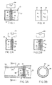
- FIG. 2A shows a gas sensor 26 having reference chamber 12 and an electrochemical cell comprising membrane 16, electrodes 18 and 20, and rigid supports 17 and 19 exposed to the gas pressure to be measured.
- Reference chamber 12 contains an electrochemically active gas, which can be oxygen. If electrode 20 is exposed to an air mixture, the oxidation-reduction process occurring across the electrochemical cell will induce a voltage between electrodes 18 and 20 which is related to the ratio of the electrochemically active gas pressure in reference chamber 12 to the electrochemically active gas pressure in air mixture 28.
- the embodiment illustrated in Figure 2A acts to measure the partial pressure of the electrochemically active gas component of air mixture 28.
- the desired component whether hydrogen, oxygen or a selected halogen, is established by the chemical properties of the electrochemically active gas contained in reference chamber 12.
- a similar partial-pressure gas sensor embodiment is illustrated.
- a semi-pervious membrane 30 is added to cover the electrochemical cell assembly to prevent evaporation of the moisture content of ionomer 16.
- Membrane 30 is selected to be pervious to the electrochemical gas to be measured while also being impervious to moisture.
- the third illustrated embodiment of interest is the dual-chamber force sensor shown in Figure 8, which is discussed in detail later below.
- FIG. 3B shows a section through Figure 3A illustrating the conductors 32 and 34 plated on the outside and inside, respectively, of the catheter tube 36.
- Conductors 32 and 34 provide connection means to electrodes 18 and 20 for monitoring the output voltage of the electrochemical cell in response to the pressure ratio to reference chamber 12 to sensing chamber 14.
- Catheter 36 is substantially 1.6mm in diameter.
- the electrical connection to electrode 18 is provided by contact with rigid conducting wall 38 in contact with inner-plated electrode 34.
- Electrical connection to electrode 20 is provided by metallic inset 40 in contact with outer plated electrode 32.
- Equation (2) is valid for an electrochemical pressure sensor using hydrogen as the electrochemically active gas. For example, if P R equal 1.01, voltmeter 24 will read a voltage of 0.13 mV.
- the pressure in chamber 12 may assume any value, including zero.
- the electrochemical pressure sensor can operate at any pressure level up to the mechanical limits of membrane 16. To prevent excessive pressure differentials across membrane 16, reference pressures in reference chamber 12 can be established to approximate the external pressure to be measured in sensor chamber 14.
- gases other than hydrogen may be used. Suitable gases include any that can participate in a reversible redox reaction, such as oxygen/water, chlorine/hydrochloric acid, etc.
- gases include any that can participate in a reversible redox reaction, such as oxygen/water, chlorine/hydrochloric acid, etc.
- Electrodes 18 and 20 in Figure 1 can be from about 5 to about 20 mils thick (0.13 mm to 0.50 mm). Electrodes 18 and 20 should be sufficiently electrochemically active to avoid undesirable and unpredictable overpotentials and may consist of platinum or palladium metal black, rigidly supported by porous metal or non-conducting rigid supports 17 and 19. Electronic conduction from electrodes 18 and 20 can be provided by metal screen or similar current carriers.
- Electrodes 18 and 20 may comprise several isolated pairs covering separate portions of the surface area of membrane 16. These pairs may be interconnected for enhanced output voltage, or separately connected for active pumping, passive sensing, or both, using well-known electrical techniques. Two isolated pairs are preferred for the active/passive applications shown in Figures 5, 8 and 9, although a single pair can provide both active and passive functions with the appropriate control means as disclosed later below in connection with Figure 6.
- chambers 12 and 14 are not critical because the sensor output is related to the ratio of pressures rather than the rate of ionic transfer across membrane 16.
- Diaphragm 22 can also be a bellows or other similar flexible structure designed to respond to pressure fluctuations.
- sensor 26 will function as an oxygen sensor.
- protective film 30 can be placed over electrode 20 as shown in Figure 2B. Film 30 can be a silicon sheet or other similar semi-pervious material.
- the illustrated embodiments of the present invention are capable of converting pressure ratios into voltage according to Equation 1 above.
- Either a known reference pressure or the self-calibration method discussed below will enable the illustrated embodiments to accurately measure absolute pressure.
- One useful method for providing a known reference pressure is to pump reference chamber 12 down to a high vacuum (zero pressure).
- electrochemical active gases tend to diffuse across ionomer 16 in response to the pressure difference between chambers 12 and 14, eventually achieving pressure equality between chambers 12 and 14.
- An important part of the present invention comprises means for inducing a gas counterflow canceling the pressure-induced diffusion across membrane 16. This is accomplished by applying a bias current in the direction opposite to the diffusion flux.
- the equilibration involves the following parameters:
- a diffusion flux compensation bias current can be computed from voltage V measured by voltmeter 24 in Figure 1 and initial pressure P 1 in reference chamber 12. This bias current is useful for maintaining accuracy in sensors operating over high pressure ranges but is not necessary for sensors operating over low pressure ranges.
- this diffusion represents a change in pressure of ⁇ 0.1% /day . That is, if reference chamber 12 pressure is initially at 760 mmHg, it will be stable for long periods, drifting only 0.2%/day if and when used at the maximum 1,000 mmHg level. Therefore, we see that device stability is adequate for all reasonable purposes over low pressure ranges without using diffusion compensation bias current means.
- reference chamber 12 pressure is initially established at 1 atmosphere. If the pressure in sensor chamber 14 is 10 atmospheres, the hydrogen diffusion rate would be 4(10) - 3 cm 3 /day. For a reference chamber 12 volume of 0.05 cm 3 , this diffusion represents a drift rate of 8%/day. A 3.3 microampere bias current opposed to the direction of this diffusional flow will maintain a constant 1 atmosphere pressure in reference chamber 12, according to Equation (4) above.
- An important feature of the present invention is the capability for self-calibration of the sensor embodiment illustrated in Figures 1 and 4.
- the following discussion demonstrates how the known volumes V 1 and V 2 shown in Figure 4 can be used to compute unknown pressures P 1 and P 2 for any dual-chamber electrochemical pressure sensor.
- Equations 9 express the pressures P 1 and P 2 in chambers 12 and 14 (having known Volumes V 1 and V 2 ) in terms of voltage measurements E and E' and physical constants a and b.
- This self-calibration method is useful in a pressure sensor embodiment employing local control means such as are illustrated in Figure 5. Although a diffusion compensation bias current will minimize sensor calibration drift, the relationships in Equations (9) will allow sensor recalibration at any time to correct for any draft that is not compensated in the bias current.
- sensor 10 is configured essentially as described above for Figure 1, with the addition of temperature sensor 42. Temperature sensor 42 is required because Equations 1 and 5 are temperature-dependent. Voltmeter 24 and temperature sensor 42 provide analog signals to A/D converter 44. Converter 44 passes the digital temperature and pressure data to microprocessor 46. Microprocessor 46 performs several functions under stored-program control. First, the pressure data from voltmeter 24 is converted to a form suitable for display 48. The diffusion compensation bias current from Equation 4 is computed by microprocessor 46 and passed to current controller 50, which accordingly adjusts the current level through ionomer membrane 16 by means of variable resistor 52 and voltage source (battery) 54.
- components 42 through 54 can be eliminated, making the embodiment identical to that illustrated in Figure 1.
- the electrochemical pressure sensor principle can be used in two different ways to monitor differential pressure within an electrochemical device as illustrated in Figure 6.
- One method uses the single pair of drive electrodes to monitor pressure during a brief interrupt period. Assuming that hydrogen gas is used with palladium black electrodes, the gas is shuttled back and forth between the pump chambers 56 and 58 by means of current controller 50 and variable resistor 52. The reciprocating transfer of gas can be part of a work-producing process within an electrochemical motor (not shown).
- Current controller 50 initiates a current interrupt in the driver circuit by way of interrupter 60.
- Voltage sensor 24 and temperature sensor 42 provide information to A/D converter 44 and microprocessor 46, which operates on the data to produce the pressure ratio shown by display 48.
- V D IR D + 0.013 ln P 2 /P 1 , where R D is the resistance of ionic membrane 16.
- the dual-chamber sensor of Figures 1 and 5 is useful for passive or reactive sensing modes.
- the passive sensing mode merely provides an electrical voltage output, which varies as a function of the measured pressure.
- the reactive sensing mode provides the pressure sensing output and also maintains a desired pressure at the measurement point in response to a drive current imposed on the sensor.
- Figure 8 illustrates a dual-chamber sensor embodiment that will effect a desired force at the measurement point.
- Figure 7 illustrates the behavior of a reactive contact sensor for various modes of operation.
- Figure 7A illustrates the behavior of a passive sensor having no interaction with the applied force.
- the applied force characteristic 82 causes the gas pressure characteristic 84 and the sensor output voltage characteristic 86.
- the important feature in Figure 7A is the similar shape of applied force characteristic 82, gas pressure characteristic 84 and sensor output voltage characteristic 86.
- Figure 7B illustrates sensor operation as a proximity sensor to maintain a zero force contact.
- the reactive drive current required to maintain a zero net force balance against force characteristic 82 is shown as driver current characteristic 88.
- the combination of force characteristic 82 and current characteristic 88 results in gas pressure characteristic 90 and sensor output voltage characteristic 92. Note that gas pressure characteristic 90 is essentially flat.
- Figure 7C illustrates a similar sensor reactive mode where the sensor acts as a forced contact sensor or effector to maintain a non-zero contact force.
- Driver current 94 is imposed on the contact sensor by control means (not shown) responsive to the applied force 82.
- Gas pressure characteristic 96 and sensor output voltage characteristic 98 result from the combination of force characteristic 82 and current characteristic 94. Note that both pressure and voltage output start at zero and rise quickly to the desired force level, maintaining a substantially fixed force level thereafter.
- Figure 7 shows how a passive sensor responds to an externally applied force by means of a voltage and a reactive sensor maintains a soft contact (zero force) or a hard contact (non-zero force) with the environment in response to stored-program control.
- the reactive sensor responds to the external force stimulus by applying a current to electrochemical cell membrane 16 which changes the gas pressure in sensor chamber 14.
- Figure 8 illustrates such a reactive force sensor.
- sensor chambers 12 and 14 and rigidly-supported membrane 16 act as described for Figure 1 above.
- Electrical conductors 68 and 70 provide access to one or more pairs of sensing electrodes (not shown) and electrical conductors 72 and 74 provide access to one or more independent pairs of active driving electrodes (not shown) on a single membrane 16. Both sets of electrodes are isolated from one another and disposed on either side of membrane 16 in the manner disclosed for Figures 1 and 5.
- Bellows 76 and contactor 78 act to transmit the external force sensed at 80 to sensing chamber 14.
- chamber 14 is shown larger than chamber 12.
- Figure 8B chamber 12 is enlarged with respect to chamber 14 and the area of membrane 16 is also enlarged to permit high transfer rates at reasonably constant storage pressure levels in chamber 12.
- Figure 9A shows a multiple reactive force sensor with more than one independent sensor sharing the same reference chamber 12.
- each sensor operates separately under local stored-program control and will effect two external forces 180 and 280.
- the two or more contactors share the same sensor chamber 14.
- a single electrolytic membrane 16 will operate to control several contactors having a single sensor chamber 14 pressure, effecting a single external fore 80 with two contactors 178 and 278.
- the illustrated embodiments in Figure 9A are useful for robotic manipulator applications with the addition of appropriate local microprocessor control routines of a type well-known in the control arts and similar to those mentioned with respect to Figure 7.
- the illustrated embodiment from Figure 1 can include a bellows or a diaphragm sensing chamber or equivalent. With a bellows sensing chamber, the sensor can be used to measure pressure in a manner than incorporates a self-calibration step. Referring to Figure 10, this "flexible wall" concept can be understood from the following description.
- the calibration of the senor is accomplished at P e less than any pressure within the intended measurement ranges.
- a current I flows from batter 54 until bellows 104 makes contact with rigid wall 100 as determined by means for monitoring the electrical conductivity from 100 to 104 (not shown).
- P 2 P s /(e bE2 ) can be computed because P 1 and E 2 are known.
- This technique is an alternative self-calibrating pressure sensing method suitable for use with the illustrated embodiment of the dual-chamber sensor shown in Figure 10.
Landscapes
- Physics & Mathematics (AREA)
- General Physics & Mathematics (AREA)
- Chemical & Material Sciences (AREA)
- Chemical Kinetics & Catalysis (AREA)
- Measuring Fluid Pressure (AREA)
- Measuring Oxygen Concentration In Cells (AREA)
Abstract
Description
- This invention involves generally devices for sensing and effecting force and pressure and more particularly involves a pressure transducer that reversibly converts mechanical force or pressure into an electrical voltage by means of an electrochemical process.
- Several methods for measuring force and pressure are known in the art. Except for gravity column measurements, such methods generally use a pressure transducer to convert applied pressure to an electrical voltage. Pressure transducers generally rely on an intermediate physical displacement induced by the applied pressure to generate an electrical voltage. The transduction principles or means of transforming a change in physical displacement into a change in electrical voltage or current circuit are as varied as the many physical relationships known to modern science. However, the transduction techniques in general use are limited to a relative few. These are essentially those which involve variations in resistance, inductance, and reluctance. Useful data are obtained by supplying such transducers with an input voltage and developing an output voltage as a function of the changes in displacement produced as an intermediate result of the application of the pressure or force to be measured.
- Of the remaining transduction principles, the piezoelectric and vibrating-wire types are most commonly used. The piezoelectric transducer uses a crystalline material that produces an output voltage proportional to the rate of change in strain over time. Because the output voltage is generated only under dynamic conditions, the piezoelectric device cannot be used for static or steady-state pressure or force measurements. It is normally used as a miniature instrument intended to measure vibration or dynamic pressure.
- The vibrating-wire transducer comprises a fine wire supported so that its tension and strain varies according to the applied pressure or force. When this wire lies between the poles of a permanent magnet, it vibrates at its natural frequency upon application of an oscillating voltage. The vibrating-wire transducer output is an oscillating voltage that changes in frequency according to changes in the wire tension induced by the applied pressure or force.
- Each of these transducer principles requires a displacement to generate a voltage output from the sensor. Pressure measurements are achieved by summing applied pressure over a flexible material that in turn is permitted limited travel. The flexible member may be a diaphragm, capsule, bellows or several variations of bourdon tubes. Each of these provides a limited displacement under applied pressure. Absolute pressures are generally determined by sealing either the capsule or bellows assembly, or the instrument chamber, at a reference pressure usually close to zero. Gauge pressure (relative to ambient atmospheric pressure) is generally measured by connecting the reference side of the instrument to the ambient condition. Differential pressure can be measured by permitting the two pressures in question access to opposite sides of the sensing member.
- Each of the above-mentioned transduction techniques is subject to several limitations. Except for the piezoelectric transducer, all such methods require a separate voltage source. The piezoelectric transducer requires no separate voltage source, but it is not useful for static pressure measurement. Again except for the piezoelectric transducer, none of the above transduction techniques are amenable to self-calibration. Although a piezoelectric transducer can be self-calibrated by means of the reciprocity principle, this method is useful only for dynamic (sinusoidally-varying) pressures. A simple, self-calibrating pressure sensor that can be calibrated to accurately sense the absolute value of static pressure without reference to a calibration standard is unknown in the art.
- In addition to the simple measurement of force or pressure, two other related sensing requirements exist in the art. First, there is often a requirement for measurement of the partial-pressure of a gas in a mixture of gases. For instance, the direct sensing of the partial-pressure of oxygen (O2) is required in the arts of medicine, biology, automotive engineering, chemistry, petroleum engineering, and others. Secondly, in the emerging robotics arts there is a well-known requirement for a transducer that combines the capacity to sense force or pressure with the capacity to effect a desired force or pressure. Such a device may be considered a force or pressure sensor/effector and is useful for robotic manipulators. The above-mentioned force transduction techniques cannot meet either of these important requirements because the transduction phenomenon is either nonreversible or (in the case of the piezoelectric transducer) the transduction phenomenon does not exist under static conditions.
- Another method for measuring the partial pressure of oxygen was demonstrated by R. Richter at Jet Propulsion Laboratory in 1984, as reported in Richter, R., "Measuring Absolute Oxygen Pressure," NASA Tech Brief 8, No. 3, Item #97. Richter did his work with a high temperature (>1000°c) zirconia-electrolyte fuel cell, using it to measure the partial-pressure of oxygen. Richter's method is not useful for measuring the partial-pressure of oxygen. Richter's method is not useful for measuring the partial-pressure of other electrochemically active gases (eg. H2, Cl2, et al) at ambient temperature.
- An electrochemical cell is typically formed by positioning an electrolytic membrane between and in contact with a cathode and an anode. Although such a cell can either generate electricity (as a fuel cell) or do mechanical work (as a motor), it has not heretofore been used as a transducer for the sensing or effecting of force and pressure. When the cell is configured as a fuel cell to generate electricity, a fuel gas such as hydrogen is supplied to the anode and a gaseous oxidant such as oxygen is supplied to the cathode, as disclosed by Wentworth in U.S. Patent 3,418,168. When the cell is configured as a motor to produce mechanical energy, an electrical voltage is applied across the anode and cathode and an electrochemically active gas capable of entering into an oxidation/reduction reaction is supplied to the anode, as disclosed by Maget in U.S. Patent 4,402,817. Neither of these patents teaches or suggests the use of an electrochemical cell as a force or pressure sensor. Such an application is briefly disclosed by the inventor in copending patent application 07/563,050 entitled "Efficient Electrochemical Motor" filed concurrently herewith.
- According to a first aspect of the invention, there is provided a force sensor comprising:
- a fluid-tight housing, having two ends and a first wall at a first end;
- a flexible diaphragm having a contacting surface for transferring an external force to said sensor, said flexible diaphragm disposed to form a second wall at a second end of said fluid-tight housing and defining therein a storage chamber for holding a supply of electrochemically active gas;
- a rigidly supported electrolytic membrane having two sides disposed between said first and second walls to divide said storage chamber into a smaller storage chamber and a sensor chamber;
- at least one pervious electrode disposed on each said side of and in contact with said electrolytic membrane;
- said at least one electrode on the first side of said electrolytic membrane being separated from one another by spaces and said at least one electrode on the second side of said electrolytic membrane being disposed to form, with said at least one electrode on said first side, at least one electrode pair separated by said electrolytic membrane;
- said gas being electrochemically reversibly active so as to enter into an anodic reaction at one side of said at least one electrode pair where the gas molecules are converted to ions transportable through said electrolytic membrane and a cathodic reaction at the opposite side of said at least one electrode pair where said ions are reconverted to gas molecules; and
- measurement means for measuring the voltage between said at least one electrode pair.
- The invention also includes a force sensor/effector comprising the force sensor described in relation to said first aspect and further comprising:
- means for providing a reversible electric current to said at least one electrode pair, said current acting to transport said ions through said electrolytic membrane whereby said gas is pumped reversibly from said storage chamber to said sensor chamber and back; and
- control means for varying the magnitude and direction of said electric current to cause said gas to flow from one said chamber to the other.
- According to a second aspect of the invention there is provided a method for determining the pressure of an electrochemically active gas in a storage chamber and a sensor chamber of an electrochemical fluid pressure sensor having an electrolytic membrane with at least one electrode pair comprising the steps of:
- measuring the voltage between said at least one electrode pair;
- providing an electric current to said at least one electrode pair for a time;
- remeasuring the voltage between said at least one electrode pair; and
- computing the electrochemically active gas pressure on both said sides of said electrolytic membrane.
- According to a third aspect of the invention there is provided a method for calibrating a dual-chamber electrochemical pressure sensor having an electrolytic membrane with at least one electrode pair and a rigid wall disposed in contact with the flexible wall of the sensor chamber the chambers containing an electrochemically active gas, comprising the steps of:
- measuring the voltage between said at least one electrode pair when said flexible and rigid walls are in contact and the measured pressure is known;
- providing an electric current to said at least one electrode pair for the time necessary to cause said flexible and rigid walls to make contact when the measured pressured is unknown:
- remeasuring the voltage between said at least one electrode pair when said flexible and rigid walls are in contact; and
- computing the unknown measured pressure.
- The present invention offers several advantages over the related art. The electrochemical transduction phenomenon is reversible, which means that the present invention is well-suited for both sensing and applying or effecting a force. The precision of the electrochemical force sensor/effector exceeds 0.05% without special provision for internal calibration because of the nature of the transduction phenomenon.
- An additional advantage arising from the reversibility of the transduction phenomenon is the capability for a simple self-calibrating procedure. The dual-chamber embodiment of the electrochemical pressure sensor can be self-calibrated merely by first measuring the output voltage, applying a known direct current for a known period of time, and remeasuring the output voltage. Using a simple algebraic relationship, the absolute pressure of the electrochemical gas on both sides of the electrolytic membrane can be calculated with an accuracy and precision limited only by the electrical voltage and current measurement means. The applicable formula can be understood from an examination of the electrochemical transduction phenomenon, wherein the current flow through the electrolytic membrane is equal to the number of ions transported across the membrane per unit time. Because the gas pressure ratio across the electrolytic membrane is also related to the number of ions (gas molecules) transported across the membrane, an exact relationship exists between membrane current and membrane pressure ratio. That is, the number of electrons flowing is precisely related to the number of gas molecules transported, except for diffusion losses induced by the pressure differential across the electrolytic membrane. Simple control means for applying a bias current to the electrolytic membrane in response to the sensor voltage output will compensate for diffusion losses. That is, a counter-diffusion gas flow can be automatically induced by a controller in response to a diffusion estimate computed for the measured pressure differential.
- Yet another advantage of the present invention arising from the reversibility of the electrochemical transduction phenomenon is the capacity for effecting a desired force using the same sensing device. This has application to the robotic arts for use in a mechanical gripper or manipulator. Most contact sensors are passive. Mechanical effectors require considerable feedback and computation to allow a manipulator to react to contact forces. The present invention permits an embodiment that can sense and react to contact forces with simple local control means involving simple feedback of sensor output voltage to a means for applying current to the electrolytic membrane. The force applied by the effector/sensor responds immediately and precisely to the applied current.
- Because the electrolytic membrane will transport only molecules of the electrochemically active gas involved in the ionic reaction at the membrane surface, the present invention is uniquely suited to the measurement of partial-pressure of selected electrochemically active gases such as hydrogen, oxygen, and the halogens. In fact, if one surface of the electrolytic membrane is exposed to the gas under measurement, the electrolytic membrane output voltage will always be directly related to the ratio of partial-pressures across the electrolytic membrane and not to the ratio of gas mixture pressures.
- Another advantage of the present invention is its suitability for miniaturization. The output voltage from the electrolytic membrane is not related to the membrane area. Thus, for instance, membranes with areas of less than 2 mm2 can function effectively as pressure sensors for use within catheters for measurement of internal blood and tissues pressures. Because the typical pressure sensor transducer known in the art relies on some physical displacement to generate the transducer output signal, these sensors often comprise a number of moving parts, thereby limiting the practicality of miniaturization.
- Finally, the present invention offers the additional advantages of high efficiency, low power requirements, and flexible geometry. All of these advantages together with the absence of moving parts (other than a flexing bellows or diaphragm) result in a low production cost for the preferred embodiments of the present invention.
- An integrated sensor/effector embodiment includes an additional micro-controller for the electrochemical cell drive current and is responsive to the electrochemical cell output voltage (sensed pressure) and a remote robotics-controller signal that establishes the desired contact. This local micro-controller responds to the sensed force by changing the drive current and thereby the gas pressure under the diaphragm or bellows. The locally-controlled pressure change constitutes a physical contact interaction with the external environment useful for robotic mechanical manipulators.
- The present invention is also ideally suited for application as an internal pressure sensor in an electrochemical motor as disclosed in copending application 07/563,050 by the inventor, entitled "Efficient Electrochemical Motor," filed concurrently herewith.
- The foregoing, together with other features and advantages of the present invention,will become more apparent when referring to the following specifications, claims and accompanying drawings.
- For a more complete understanding of the present invention, reference is now made to the following detailed description of the embodiments illustrated in the accompanying drawings, wherein:
- Figure 1 is a schematic illustration of a dual-chamber electrochemical pressure sensor;
- Figure 2, comprising Figures 2A and 2B, is a schematic illustration of two different versions of a single-chamber electrochemical partial-pressure sensor;
- Figure 3 is a schematic illustration of an electrochemical pressure sensor used as an integral part of a catheter;
- Figure 4 is a schematic illustration of a single gas storage chamber bisected by an electrolytic membrane;
- Figure 5 is a schematic diagram of an electrochemical pressure sensor having provision for diffusion-canceling bias current feedback;
- Figure 6 is a schematic diagram of an electrochemical pressure sensor showing electrical components for dynamic pressure ratio display;
- Figure 7, comprising Figures 7A, 7B and 7C, illustrates the applied force, gas pressure, and sensor voltage characteristics versus time for both a passive and a reactive electrochemical pressure sensor/effector;
- Figure 8, comprising Figures 8A and 8B, illustrates two configurations of an electrochemical force sensor/effector having a bellows and piston contactor arrangement; and
- Figure 9, comprising Figures 9A and 9B, illustrates two multiple force sensor/effector configurations with robotic manipulator applications.
- Three illustrated embodiments of the present invention are of primary interest as pressure and force sensors and effectors.
- Figure 1 illustrates a dual-
chamber pressure sensor 10 showing areference chamber 12 and asensing chamber 14 separated by a rigidly-supportedelectrolytic membrane 16 havingpervious conductors membrane 16 and rigid supporting printed-circuit boards (PCB's) 17 and 19 on either side of the electrode/ionomer assembly. Sensingchamber 14 comprises aflexible diaphragm 22 which deforms under the external measured pressure, until the pressure within sensingchamber 14 is equal to the external measured pressure. Bothchambers Rigid supports electrodes ionomer 16. - When the pressure in
chamber 12 is different fromchamber 14, well-known processes occur which result in the reduction of gas molecules at the surface betweenelectrode 12 andionomer 16 and oxidation of gas ions at the interface betweenionomer 16 andelectrode 20. As part of this process, in the case of hydrogen gas, an electron is removed fromelectrode 18 for each such reduction and an electron is added toelectrode 20 for each such oxidation. This process is reversed merely by inverting the pressure ratio ofchambers electrodes voltmeter 24. If the internal impedance ofvoltmeter 24 is very high, no current will flow betweenelectrodes membrane 16, thereby maintaining the relative pressure difference betweenchambers - The practical application of this electrochemical transduction phenomenon requires the use of a rigidly-supported electrolytic cell illustrated as a combination of
membrane 16,electrodes - Also, refer to LaConti, A. B., et al., "Electrode Materials and Processes for Energy Conversions."
ECS Proceedings, pp. 354-374, 1977. - The second illustrated embodiment of interest is the partial-pressure gas sensor illustrated in Figure 2. Figure 2A shows a
gas sensor 26 havingreference chamber 12 and an electrochemicalcell comprising membrane 16,electrodes rigid supports Reference chamber 12 contains an electrochemically active gas, which can be oxygen. Ifelectrode 20 is exposed to an air mixture, the oxidation-reduction process occurring across the electrochemical cell will induce a voltage betweenelectrodes reference chamber 12 to the electrochemically active gas pressure inair mixture 28. Thus, it is seen that the embodiment illustrated in Figure 2A acts to measure the partial pressure of the electrochemically active gas component ofair mixture 28. The desired component, whether hydrogen, oxygen or a selected halogen, is established by the chemical properties of the electrochemically active gas contained inreference chamber 12. - Referring to Figure 2B, a similar partial-pressure gas sensor embodiment is illustrated. However, a
semi-pervious membrane 30 is added to cover the electrochemical cell assembly to prevent evaporation of the moisture content ofionomer 16.Membrane 30 is selected to be pervious to the electrochemical gas to be measured while also being impervious to moisture. - The third illustrated embodiment of interest is the dual-chamber force sensor shown in Figure 8, which is discussed in detail later below.
- Referring to Figure 3, dual-
chamber pressure sensor 10 is incorporated in a catheter-based embodiment suitable for medical applications. Figure 3B shows a section through Figure 3A illustrating theconductors catheter tube 36.Conductors electrodes reference chamber 12 to sensingchamber 14.Catheter 36 is substantially 1.6mm in diameter. The electrical connection toelectrode 18 is provided by contact with rigid conductingwall 38 in contact with inner-platedelectrode 34. Electrical connection toelectrode 20 is provided bymetallic inset 40 in contact with outer platedelectrode 32. - To illustrate the electrochemical pressure-sensing phenomenon in more detail, consider Figures 1 and 4. The volumes of
chambers Reference chamber 12 contains a known amount of electrochemically active gas, such as oxygen or hydrogen, and is used as a reference pressure. In Figure 4, this reference pressure is P1. If sensingchamber 14 is initially also at pressure P1, the system is in equilibrium and the voltage atvoltmeter 24 is zero. If the external pressure increases to P2, a pressure differential is created betweenchambers 
- V =
- voltage between
electrodes - R =
- gas constant,
- T =
- absolute temperature in °K,
- n =
- the number of electrons involved in the electrochemical redox process per molecule of active gas (n = 2 for the redox couple hydrogen/hydrogen), and
- F =
- Faraday constant.
- The coefficient (RT/nF) is substantially equal to 13 mV at room temperature. If PR is defined as the pressure ratio P2/P1 and if PR approaches unity, Equation (1) can be rewritten as:

- Equation (2) is valid for an electrochemical pressure sensor using hydrogen as the electrochemically active gas. For example, if PR equal 1.01,
voltmeter 24 will read a voltage of 0.13 mV. - Because
sensor 10 is completely enclosed and sealed, the pressure inchamber 12 may assume any value, including zero. The electrochemical pressure sensor can operate at any pressure level up to the mechanical limits ofmembrane 16. To prevent excessive pressure differentials acrossmembrane 16, reference pressures inreference chamber 12 can be established to approximate the external pressure to be measured insensor chamber 14. - Obviously, gases other than hydrogen may be used. Suitable gases include any that can participate in a reversible redox reaction, such as oxygen/water, chlorine/hydrochloric acid, etc. To illustrate the use of other redox couples, consider the oxygen/water system. If oxygen is present in
chambers ionomer 16, then all the chemical components of the redox couple are available. Equations (1) and (2) are applicable except that n = 4 and Equation (2) becomes V = 0.0065 (R-1). -
Membrane 16 in Figure 1 can be from about 5 to about 20 mils thick (0.13 mm to 0.50 mm).Electrodes rigid supports electrodes - The design of
electrodes Electrodes membrane 16. These pairs may be interconnected for enhanced output voltage, or separately connected for active pumping, passive sensing, or both, using well-known electrical techniques. Two isolated pairs are preferred for the active/passive applications shown in Figures 5, 8 and 9, although a single pair can provide both active and passive functions with the appropriate control means as disclosed later below in connection with Figure 6. - The design of
chambers membrane 16.Diaphragm 22 can also be a bellows or other similar flexible structure designed to respond to pressure fluctuations. - In Figure 2A, if
chamber 12 is filled with oxygen or air,sensor 26 will function as an oxygen sensor. To avoid contamination or drying ofionomer 16,protective film 30 can be placed overelectrode 20 as shown in Figure 2B.Film 30 can be a silicon sheet or other similar semi-pervious material. - The illustrated embodiments of the present invention are capable of converting pressure ratios into voltage according to
Equation 1 above. Either a known reference pressure or the self-calibration method discussed below will enable the illustrated embodiments to accurately measure absolute pressure. One useful method for providing a known reference pressure is to pumpreference chamber 12 down to a high vacuum (zero pressure). However, electrochemical active gases tend to diffuse acrossionomer 16 in response to the pressure difference betweenchambers chambers membrane 16. This is accomplished by applying a bias current in the direction opposite to the diffusion flux. The equilibration involves the following parameters: - Voltage due to pressure ratio, V=0.013 ln P2/P1 (for hydrogen/hydrogen);
- Gas flux induced by the pressure differential, F=A(P1-P2), where the proportionality factor, A can be known accurately.
- If a current I is applied to oppose flux F, then I = -kA(P2-P1) where k is the factor is relating current to gas flow.
- Current I can be obtained from the above:

- At room temperature, Equation (3) yields


- Thus, we see that a diffusion flux compensation bias current can be computed from voltage V measured by
voltmeter 24 in Figure 1 and initial pressure P1 inreference chamber 12. This bias current is useful for maintaining accuracy in sensors operating over high pressure ranges but is not necessary for sensors operating over low pressure ranges. - To illustrate this, consider the embodiment in Figure 3. Assume that pressure measurements are required over the range from 760 to 1,000 mmHg, such as found in the human body at sea level. Assume also that P1 is maintained at 880 mmHg initially, and thus varied ± 120 mmHg. If a hydrogen electrode is selected and the hydrogen permeation rate across
ionomer 16 is 10-8(cm3/sec)/cm2-area/cm- thickness/atm. For a 0.02 cm2 area and a 0.05 cm thickness, the diffusion rate will vary between zero and ±6(10)-10 cm 3/sec or about 5(10)-5cm3/day. If the volume of gas inreference chamber 12 is 0.05 cm3, then this diffusion represents a change in pressure of ±0.1%/day. That is, ifreference chamber 12 pressure is initially at 760 mmHg, it will be stable for long periods, drifting only 0.2%/day if and when used at the maximum 1,000 mmHg level. Therefore, we see that device stability is adequate for all reasonable purposes over low pressure ranges without using diffusion compensation bias current means. - Considering applications of
sensor 10 at high pressure ranges, such as 1-10 atmospheres, assume thatreference chamber 12 pressure is initially established at 1 atmosphere. If the pressure insensor chamber 14 is 10 atmospheres, the hydrogen diffusion rate would be 4(10)- 3cm3/day. For areference chamber 12 volume of 0.05 cm3, this diffusion represents a drift rate of 8%/day. A 3.3 microampere bias current opposed to the direction of this diffusional flow will maintain a constant 1 atmosphere pressure inreference chamber 12, according to Equation (4) above. - An important feature of the present invention is the capability for self-calibration of the sensor embodiment illustrated in Figures 1 and 4. The following discussion demonstrates how the known volumes V1 and V2 shown in Figure 4 can be used to compute unknown pressures P1 and P2 for any dual-chamber electrochemical pressure sensor.
- The calculation of P1 and P2 are based on the relationship of open circuit voltage E and pressure ratio PR from Equation (1):

- First, measure E, which will yield


- The relationship for drive current I (amps) for time t (seconds) in either direction is then:

- The pressures now become:

- Measure the new open circuit voltage E' such that


- Approximating, for small values of bE and bE',

- Thus,


- Note that Equations 9 express the pressures P1 and P2 in
chambers 12 and 14 (having known Volumes V1 and V2) in terms of voltage measurements E and E' and physical constants a and b. This self-calibration method is useful in a pressure sensor embodiment employing local control means such as are illustrated in Figure 5. Although a diffusion compensation bias current will minimize sensor calibration drift, the relationships in Equations (9) will allow sensor recalibration at any time to correct for any draft that is not compensated in the bias current. - Referring to Figure 5,
sensor 10 is configured essentially as described above for Figure 1, with the addition oftemperature sensor 42.Temperature sensor 42 is required becauseEquations 1 and 5 are temperature-dependent.Voltmeter 24 andtemperature sensor 42 provide analog signals to A/D converter 44.Converter 44 passes the digital temperature and pressure data tomicroprocessor 46.Microprocessor 46 performs several functions under stored-program control. First, the pressure data fromvoltmeter 24 is converted to a form suitable fordisplay 48. The diffusion compensation bias current from Equation 4 is computed bymicroprocessor 46 and passed tocurrent controller 50, which accordingly adjusts the current level throughionomer membrane 16 by means ofvariable resistor 52 and voltage source (battery) 54. - For operating conditions where the pressure range is narrow and the temperature is constant,
components 42 through 54 can be eliminated, making the embodiment identical to that illustrated in Figure 1. - Experimental tests of the embodiment illustrated in Figure 5 (at 24.3°C, with palladium electrodes) has confirmed that the equilibrium voltage equals 50 + 12800 ln (P2/P1) in microvolts between 1 and 2 atmospheres. The 50 microvolt bias voltage is probably the result of slight differences between the electrodes or a difference in ion concentration at one of the two electrode-membrane interfaces. The theoretical value of the coefficient is 12818 microvolts, which is substantially identical to the measured value. A voltmeter reading error of 10 microvolts is equivalent to an error in pressure of 0.6 mmHg. At a pressure of 1.5 atm, this is equivalent to a precision of 0.05%, which demonstrates the high precision of the present invention.
- As previously suggested, the electrochemical pressure sensor principle can be used in two different ways to monitor differential pressure within an electrochemical device as illustrated in Figure 6. One method uses the single pair of drive electrodes to monitor pressure during a brief interrupt period. Assuming that hydrogen gas is used with palladium black electrodes, the gas is shuttled back and forth between the
pump chambers current controller 50 andvariable resistor 52. The reciprocating transfer of gas can be part of a work-producing process within an electrochemical motor (not shown).Current controller 50 initiates a current interrupt in the driver circuit by way ofinterrupter 60.Voltage sensor 24 andtemperature sensor 42 provide information to A/D converter 44 andmicroprocessor 46, which operates on the data to produce the pressure ratio shown bydisplay 48. At the end of the current interrupt,voltage source 54 is reconnected by means ofinterrupter 60 at the direction ofcurrent controller 50. The interrupt duration is approximately 20-50 msec. During the motor operation, the voltage betweenelectrodes ionic membrane 16. When the drive current is interrupted, VD decays to V0 = VD - IRD = 0.013 ln P2/P1. If the decay from VD to V0 is rapid, the pressure ratio can be measured and the current restarted after only a brief delay. - This teaching demonstrates that a very brief current interrupt cycle initiated by stored-program control permits the computation and display of the pressure ratio in an electrochemical motor or a sensor/effector having a single electrode pair. A second method for monitoring pressure within the motor is to use isolated pressure-sensor electrodes on the motor membrane. This second method allows continuous monitoring of pressure, without interruption of the motor drive circuit, in the manner discussed in connection with Figure 1.
- As already mentioned, the dual-chamber sensor of Figures 1 and 5 is useful for passive or reactive sensing modes. The passive sensing mode merely provides an electrical voltage output, which varies as a function of the measured pressure. The reactive sensing mode provides the pressure sensing output and also maintains a desired pressure at the measurement point in response to a drive current imposed on the sensor. Figure 8 illustrates a dual-chamber sensor embodiment that will effect a desired force at the measurement point.
- Figure 7 illustrates the behavior of a reactive contact sensor for various modes of operation. Figure 7A illustrates the behavior of a passive sensor having no interaction with the applied force. The applied force characteristic 82 causes the gas pressure characteristic 84 and the sensor
output voltage characteristic 86. The important feature in Figure 7A is the similar shape of applied force characteristic 82, gas pressure characteristic 84 and sensoroutput voltage characteristic 86. - Figure 7B illustrates sensor operation as a proximity sensor to maintain a zero force contact. The reactive drive current required to maintain a zero net force balance against force characteristic 82 is shown as driver current characteristic 88. The combination of force characteristic 82 and current characteristic 88 results in gas pressure characteristic 90 and sensor
output voltage characteristic 92. Note that gas pressure characteristic 90 is essentially flat. - Figure 7C illustrates a similar sensor reactive mode where the sensor acts as a forced contact sensor or effector to maintain a non-zero contact force. Driver current 94 is imposed on the contact sensor by control means (not shown) responsive to the applied
force 82. Gas pressure characteristic 96 and sensor output voltage characteristic 98 result from the combination of force characteristic 82 and current characteristic 94. Note that both pressure and voltage output start at zero and rise quickly to the desired force level, maintaining a substantially fixed force level thereafter. - Figure 7 shows how a passive sensor responds to an externally applied force by means of a voltage and a reactive sensor maintains a soft contact (zero force) or a hard contact (non-zero force) with the environment in response to stored-program control. The reactive sensor responds to the external force stimulus by applying a current to
electrochemical cell membrane 16 which changes the gas pressure insensor chamber 14. Figure 8 illustrates such a reactive force sensor. - In Figure 8,
sensor chambers membrane 16 act as described for Figure 1 above.Electrical conductors electrical conductors single membrane 16. Both sets of electrodes are isolated from one another and disposed on either side ofmembrane 16 in the manner disclosed for Figures 1 and 5. Bellows 76 andcontactor 78 act to transmit the external force sensed at 80 to sensingchamber 14. In Figure 8A,chamber 14 is shown larger thanchamber 12. In Figure 8B,chamber 12 is enlarged with respect tochamber 14 and the area ofmembrane 16 is also enlarged to permit high transfer rates at reasonably constant storage pressure levels inchamber 12. - Figure 9A shows a multiple reactive force sensor with more than one independent sensor sharing the
same reference chamber 12. In this case, each sensor operates separately under local stored-program control and will effect twoexternal forces same sensor chamber 14. In this case, a singleelectrolytic membrane 16 will operate to control several contactors having asingle sensor chamber 14 pressure, effecting a single external fore 80 with twocontactors - The illustrated embodiment from Figure 1 can include a bellows or a diaphragm sensing chamber or equivalent. With a bellows sensing chamber, the sensor can be used to measure pressure in a manner than incorporates a self-calibration step. Referring to Figure 10, this "flexible wall" concept can be understood from the following description.
- Consider a
rigid wall 100 with anorifice 102 which allows external pressure Pe to pass through and depress bellows 104. The initial state of the sensor exists with no deformation of bellows 104 and withsensor chamber 14 pressure P1 = Pe such that the end of bellows 104 is in contact with rigid wall 100 (x=0). The volume Vs ofstorage chamber 12 is known. The pressure Ps ofstorage chamber 12 is unknown. - The calibration of the senor is accomplished at Pe less than any pressure within the intended measurement ranges. To calibrate, a current I flows from
batter 54 until bellows 104 makes contact withrigid wall 100 as determined by means for monitoring the electrical conductivity from 100 to 104 (not shown). At contact, distance x=0, and
voltmeter 24. - Because E1 and P1 = Pe is known, then

- Following sensor calibration, external pressure Pe is permitted to increase to a value within the intended measurement range, Pe'. Bellows 104 moves away from
wall 100 by distance x, andvoltmeter 24 now reads a voltage E2. We now have the following relationship for sensor chamber pressure P2
- Where k = bellows spring constant

- Thus; P2 Ps/(ebE2) can be computed because P1 and E2 are known.
- If bellows 104 is calibrated such that k/s is known, then Pe' = Ps + kx/s can also be computed. If the bellows is not calibrated, Pe' can be found by the following procedure.
- Drive current I for time t to reestablish contact between bellows 104 and
wall 100. Measure current I, time t andvoltmeter 24 voltage e3. - Then: P s /=P s -

- Where:
- a = A physical constant defined earlier, and
- Ps = the initial storage chamber pressure computed from the earlier calibration step at Pe.
- Thus,

- Since I, t, b, E3, Vs, a, and Ps are known,

- This technique is an alternative self-calibrating pressure sensing method suitable for use with the illustrated embodiment of the dual-chamber sensor shown in Figure 10.
- Obviously, other embodiments and modifications of the present invention will occur readily to those of ordinary skill in the relevant arts in view of these teachings. Therefore, this invention is to be limited only by the following claims, which include all such obvious embodiments and modifications when viewed in conjunction with the above specification and accompanying drawings.
Claims (11)
- A force sensor comprising:a fluid-tight housing, having two ends and a first wall at a first end;a flexible diaphragm (76) having a contacting surface (78) for transferring an external force to said sensor, said flexible diaphragm (76) disposed to form a second wall at a second end of said fluid-tight housing and defining therein a storage chamber (14) for holding a supply of electrochemically active gas;a rigidly supported electrolytic membrane (16) having two sides disposed between said first and second walls to divide said storage chamber (14) into a smaller storage chamber (14) and a sensor chamber (12);at least one pervious electrode (18,20) disposed on each said side of and in contact with said electrolytic membrane (16);said at least one electrode (18,20) on the first side of said electrolytic membrane (16) being separated from one another by spaces and said at least one electrode (18,20) on the second side of said electrolytic membrane (16) being disposed to form, with said at least one electrode (18,20) on said first side, at least one electrode pair (18,20) separated by said electrolytic membrane (16);said gas being electrochemically reversibly active so as to enter into an anodic reaction at one side of said at least one electrode pair (18,20) where the gas molecules are converted to ions transportable through said electrolytic membrane (16) and a cathodic reaction at the opposite side of said at least one electrode pair (18,20) where said ions are reconverted to gas molecules; andmeasurement means (24) for measuring the voltage between said at least one electrode pair (18,20).
- A force sensor according to claim 1 in which the sensor is arranged to sense fluid pressure.
- The force sensor of Claim 1 or 2 wherein:said fluid-tight housing is disposed inside the tip of a rigid catheter (36) comprising a long hollow cylinder having an interior and an exterior surface.
- The force sensor of Claim 1 or 2 further comprising:means (32,34) for providing a reversible electric current to said at least one electrode pair (18,20), said current acting to transport said ions through said electrolytic membrane (16) whereby said gas is pumped reversibly from said storage chamber (14) to said sensor chamber (12) and back; andcontrol means (46) for varying the magnitude and direction of said electric current to cause said gas to flow from one said chamber to the other to cancel the effects of the diffusion through said electrolytic membrane induced by the difference in gas pressure across said electrolytic membrane.
- The force sensor of claim 4 further comprising second control means (46) for accomplishing automatic calibration of said sensor.
- The force sensor of claim 5 further comprising:temperature sensing means (42) for determining the temperature of said electrochemically active gas; andsecond control means (46) responsive to said temperature sensing means (42) for accomplishing automatic calibration of said sensor.
- A force sensor/effector comprising the force sensor of Claim 1 and further comprising:means (54) for providing a reversible electric current to said at least one electrode pair (18,20), said current acting to transport said ions through said electrolytic membrane (16) whereby said gas is pumped reversibly from said storage chamber (14) to said sensor chamber (12) and back: andcontrol means (50) for varying the magnitude and direction of said electric current to cause said gas to flow from one said chamber to the other.
- The force sensor/effector of Claim 7 further comprising second control means (46) for accomplishing automatic calibration of said sensor/effector.
- The force sensor/effector of Claim 8 further comprising second control means (46) for applying said current to said at least one electrode pair (18,20) to cancel the effects of the diffusion through said electrolytic membrane (16) induced by the difference in gas pressure across said electrolytic membrane (16).
- The force sensor/effector of Claim 8 further comprising:temperature sensing means (42) for determining the temperature of said electrochemically active gas; andsecond control means (46) responsive to said temperature sensing means (42) for accomplishing automatic calibration of said sensor.
- A method for determining the pressure of an electrochemically active gas in a storage chamber (14) and a sensor chamber (12) of an electrochemical fluid pressure sensor having an electrolytic membrane (16) with at least one electrode pair (18,20) comprising the steps of:measuring the voltage between said at least one electrode pair (18,20);providing an electric current to said at least one electrode pair (18,20) for a time;remeasuring the voltage between said at least one electrode pair (18,20); andcomputing the electrochemically active gas pressure on both said sides of said electrolytic membrane (16).12. A method for calibrating a dual-chamber electrochemical pressure sensor having an electrolytic membrane (16) with at least one electrode pair (18,20) and a rigid wall disposed in contact with the flexible wall of the sensor chamber the chambers (12,14) containing an electrochemically active gas, comprising the steps of:measuring the voltage between said at least one electrode pair (18,20) when said flexible and rigid walls are in contact and the measured pressure is known;providing an electric current to said at least one electrode pair (18,20) for the time necessary to cause said flexible and rigid walls to make contact when the measured pressure is unknown;remeasuring the voltage between said at least one electrode pair (18,20) when said flexible and rigid walls are in contact; andcomputing the unknown measured pressure.
Applications Claiming Priority (3)
| Application Number | Priority Date | Filing Date | Title |
|---|---|---|---|
| US56305190A | 1990-08-06 | 1990-08-06 | |
| US563051 | 1990-08-06 | ||
| EP91306874A EP0470744B1 (en) | 1990-08-06 | 1991-07-26 | Electrochemical force sensor |
Related Parent Applications (1)
| Application Number | Title | Priority Date | Filing Date |
|---|---|---|---|
| EP91306874.8 Division | 1991-07-26 |
Publications (2)
| Publication Number | Publication Date |
|---|---|
| EP0715158A2 true EP0715158A2 (en) | 1996-06-05 |
| EP0715158A3 EP0715158A3 (en) | 1996-10-16 |
Family
ID=24248905
Family Applications (2)
| Application Number | Title | Priority Date | Filing Date |
|---|---|---|---|
| EP91306874A Expired - Lifetime EP0470744B1 (en) | 1990-08-06 | 1991-07-26 | Electrochemical force sensor |
| EP96101243A Withdrawn EP0715158A3 (en) | 1990-08-06 | 1991-07-26 | Electrochemical force and pressure sensor |
Family Applications Before (1)
| Application Number | Title | Priority Date | Filing Date |
|---|---|---|---|
| EP91306874A Expired - Lifetime EP0470744B1 (en) | 1990-08-06 | 1991-07-26 | Electrochemical force sensor |
Country Status (4)
| Country | Link |
|---|---|
| US (2) | US5334304A (en) |
| EP (2) | EP0470744B1 (en) |
| JP (1) | JP3079156B2 (en) |
| DE (1) | DE69122009T2 (en) |
Cited By (2)
| Publication number | Priority date | Publication date | Assignee | Title |
|---|---|---|---|---|
| WO2013003162A1 (en) * | 2011-06-30 | 2013-01-03 | Caterpillar Inc. | Gas monitoring system implementing pressure detection |
| US8875560B2 (en) | 2011-06-30 | 2014-11-04 | Caterpillar Inc. | System implementing constituent identification and concentration detection |
Families Citing this family (18)
| Publication number | Priority date | Publication date | Assignee | Title |
|---|---|---|---|---|
| US5529015A (en) * | 1995-02-13 | 1996-06-25 | The United States Of America As Represented By The Administrator Of The National Aeronautics And Space Administration | Ampoule failure system |
| AU7671696A (en) * | 1996-01-18 | 1997-08-11 | University Of New Mexico | Soft actuators and artificial muscles |
| US6475639B2 (en) * | 1996-01-18 | 2002-11-05 | Mohsen Shahinpoor | Ionic polymer sensors and actuators |
| US5971722A (en) * | 1997-09-05 | 1999-10-26 | Baxter International Inc | Electrochemical syringe pump having a sealed storage reservoir for a charge transfer medium |
| US6321561B1 (en) | 1999-10-01 | 2001-11-27 | Henri J. R. Maget | Electrochemical refrigeration system and method |
| WO2002058994A1 (en) * | 2001-01-24 | 2002-08-01 | Spectrx, Inc. | Vacuum device for substance extraction |
| WO2002084768A1 (en) * | 2001-04-10 | 2002-10-24 | California Institute Of Technology | Actuatable and reversible pressure generation based on fuel cell operation |
| US7074509B2 (en) * | 2001-11-13 | 2006-07-11 | Eldat Communication Ltd. | Hydrogen generators for fuel cells |
| AU2003267164A1 (en) * | 2002-09-12 | 2004-04-30 | Cook Incorporated | Retrievable filter |
| EP1778071A2 (en) * | 2004-05-25 | 2007-05-02 | Altana Pharma AG | Device and method for monitoring the functioning of the lower esophageal sphincter |
| US7043960B1 (en) | 2004-06-17 | 2006-05-16 | The United States Of America As Represented By The Administrator Of The National Aeronautics And Space Administration | Self-calibrating pressure transducer |
| JP2006058201A (en) * | 2004-08-23 | 2006-03-02 | Gas Mitsukusu Kogyo Kk | Heat conduction type gas analyzer |
| US7372277B2 (en) * | 2005-04-15 | 2008-05-13 | Agamatrix, Inc. | Method and apparatus for providing stable voltage to analytical system |
| US7943034B2 (en) * | 2006-10-19 | 2011-05-17 | Agamatrix, Inc. | Method and apparatus for providing a stable voltage to an analytical system |
| US20100108536A1 (en) * | 2008-10-30 | 2010-05-06 | Mti Micro Fuel Cells, Inc. | Electrochemical actuator |
| US20100112381A1 (en) * | 2008-10-30 | 2010-05-06 | Mti Micro Fuel Cells, Inc. | Electrochemical actuator |
| US20100108534A1 (en) * | 2008-10-30 | 2010-05-06 | Mti Micro Fuel Cells, Inc. | Electrochemical actuator |
| US9266085B2 (en) | 2010-09-09 | 2016-02-23 | Johnson Research & Development Co. Inc. | Johnson ambient-heat engine |
Citations (8)
| Publication number | Priority date | Publication date | Assignee | Title |
|---|---|---|---|---|
| US4024036A (en) * | 1975-02-03 | 1977-05-17 | Agency Of Industrial Science & Technology | Proton permselective solid-state member and apparatus utilizing said permselective member |
| JPS5537967A (en) * | 1978-09-11 | 1980-03-17 | Fuji Electric Co Ltd | Pressure measuring instrument |
| GB2051374A (en) * | 1979-05-16 | 1981-01-14 | Chloride Silent Power Ltd | Transducer |
| US4522698A (en) * | 1981-11-12 | 1985-06-11 | Maget Henri J R | Electrochemical prime mover |
| EP0209644A1 (en) * | 1985-05-02 | 1987-01-28 | Ivac Corporation | Electrochemically driven drug dispenser |
| JPS6231777A (en) * | 1985-07-31 | 1987-02-10 | Shimadzu Corp | High-pressure force sealing mechanism |
| US4718991A (en) * | 1986-01-27 | 1988-01-12 | Figaro Engineering Inc. | Proton conductor gas sensor and method of detecting gas using proton conductor gas sensor |
| JPS63148020A (en) * | 1986-12-10 | 1988-06-20 | Matsushita Electric Ind Co Ltd | Device to prevent water channel from being freezed and damaged |
Family Cites Families (23)
| Publication number | Priority date | Publication date | Assignee | Title |
|---|---|---|---|---|
| US2661430A (en) * | 1951-11-27 | 1953-12-01 | Jr Edward V Hardway | Electrokinetic measuring instrument |
| US2913511A (en) * | 1955-06-29 | 1959-11-17 | Gen Electric | Fuel cell |
| US3056908A (en) * | 1958-11-28 | 1962-10-02 | Union Carbide Corp | Electrochemical detector |
| US3342558A (en) * | 1962-04-18 | 1967-09-19 | Phillips Petroleum Co | Electrical measuring system utilizing a fuel cell |
| US3334623A (en) * | 1964-11-02 | 1967-08-08 | Beckman Instruments Inc | Electrochemical transducer |
| GB1073099A (en) * | 1965-06-10 | 1967-06-21 | Kent Ltd G | Improvements in or relating to electro-chemical gas measuring system |
| US3400054A (en) * | 1966-03-15 | 1968-09-03 | Westinghouse Electric Corp | Electrochemical method for separating o2 from a gas; generating electricity; measuring o2 partial pressure; and fuel cell |
| US3503861A (en) * | 1966-03-21 | 1970-03-31 | Emilio Volpe | Apparatus for electrochemical analyses |
| US3510421A (en) * | 1967-06-12 | 1970-05-05 | Honeywell Inc | Polarographic cell |
| US3646814A (en) * | 1970-09-16 | 1972-03-07 | Us Navy | Pressure detector |
| US3978006A (en) * | 1972-02-10 | 1976-08-31 | Robert Bosch G.M.B.H. | Methods for producing oxygen-sensing element, particularly for use with internal combustion engine exhaust emission analysis |
| BG20702A1 (en) * | 1974-07-10 | 1975-12-20 | ||
| US4158166A (en) * | 1976-11-24 | 1979-06-12 | Westinghouse Electric Corp. | Combustibles analyzer |
| JPS5748649A (en) * | 1980-09-08 | 1982-03-20 | Nissan Motor Co Ltd | Controller for air-to-fuel ratio of internal combustion engine |
| JPS57192849A (en) * | 1981-05-25 | 1982-11-27 | Toyota Central Res & Dev Lab Inc | Detecting device for limit current system oxygen concentration performing temperature compensation of measuring output |
| JPS5824855A (en) * | 1981-08-05 | 1983-02-14 | Nippon Denso Co Ltd | Oxygen concentration detector |
| US4402817A (en) * | 1981-11-12 | 1983-09-06 | Maget Henri J R | Electrochemical prime mover |
| US4648955A (en) * | 1985-04-19 | 1987-03-10 | Ivac Corporation | Planar multi-junction electrochemical cell |
| US4886514A (en) * | 1985-05-02 | 1989-12-12 | Ivac Corporation | Electrochemically driven drug dispenser |
| US4687423A (en) * | 1985-06-07 | 1987-08-18 | Ivac Corporation | Electrochemically-driven pulsatile drug dispenser |
| US4661211A (en) * | 1985-07-10 | 1987-04-28 | Uop Inc. | Gas detection with three-component membrane and sensor using said membrane |
| US4902278A (en) * | 1987-02-18 | 1990-02-20 | Ivac Corporation | Fluid delivery micropump |
| US5149413A (en) * | 1990-08-06 | 1992-09-22 | Maget Henri J R | Efficient electrochemical motor |
-
1991
- 1991-07-26 EP EP91306874A patent/EP0470744B1/en not_active Expired - Lifetime
- 1991-07-26 EP EP96101243A patent/EP0715158A3/en not_active Withdrawn
- 1991-07-26 DE DE69122009T patent/DE69122009T2/en not_active Expired - Fee Related
- 1991-08-06 JP JP03219252A patent/JP3079156B2/en not_active Expired - Lifetime
- 1991-11-18 US US07/793,459 patent/US5334304A/en not_active Expired - Lifetime
-
1993
- 1993-12-30 US US08/175,633 patent/US5417822A/en not_active Expired - Lifetime
Patent Citations (8)
| Publication number | Priority date | Publication date | Assignee | Title |
|---|---|---|---|---|
| US4024036A (en) * | 1975-02-03 | 1977-05-17 | Agency Of Industrial Science & Technology | Proton permselective solid-state member and apparatus utilizing said permselective member |
| JPS5537967A (en) * | 1978-09-11 | 1980-03-17 | Fuji Electric Co Ltd | Pressure measuring instrument |
| GB2051374A (en) * | 1979-05-16 | 1981-01-14 | Chloride Silent Power Ltd | Transducer |
| US4522698A (en) * | 1981-11-12 | 1985-06-11 | Maget Henri J R | Electrochemical prime mover |
| EP0209644A1 (en) * | 1985-05-02 | 1987-01-28 | Ivac Corporation | Electrochemically driven drug dispenser |
| JPS6231777A (en) * | 1985-07-31 | 1987-02-10 | Shimadzu Corp | High-pressure force sealing mechanism |
| US4718991A (en) * | 1986-01-27 | 1988-01-12 | Figaro Engineering Inc. | Proton conductor gas sensor and method of detecting gas using proton conductor gas sensor |
| JPS63148020A (en) * | 1986-12-10 | 1988-06-20 | Matsushita Electric Ind Co Ltd | Device to prevent water channel from being freezed and damaged |
Non-Patent Citations (3)
| Title |
|---|
| PATENT ABSTRACTS OF JAPAN vol. 004, no. 070 (P-012), 23 May 1980 & JP-A-55 037967 (FUJI ELECTRIC CO LTD), 17 March 1980, * |
| PATENT ABSTRACTS OF JAPAN vol. 011, no. 215 (M-606), 11 July 1987 & JP-A-62 031777 (SHIMADZU CORP), 10 February 1987, * |
| PATENT ABSTRACTS OF JAPAN vol. 012, no. 404 (M-757), 26 October 1988 & JP-A-63 148020 (MATSUSHITA ELECTRIC IND CO LTD), 20 June 1988, * |
Cited By (3)
| Publication number | Priority date | Publication date | Assignee | Title |
|---|---|---|---|---|
| WO2013003162A1 (en) * | 2011-06-30 | 2013-01-03 | Caterpillar Inc. | Gas monitoring system implementing pressure detection |
| US8783112B2 (en) | 2011-06-30 | 2014-07-22 | Caterpillar Inc. | Gas monitoring system implementing pressure detection |
| US8875560B2 (en) | 2011-06-30 | 2014-11-04 | Caterpillar Inc. | System implementing constituent identification and concentration detection |
Also Published As
| Publication number | Publication date |
|---|---|
| JPH04232826A (en) | 1992-08-21 |
| EP0470744A2 (en) | 1992-02-12 |
| EP0470744A3 (en) | 1993-04-28 |
| DE69122009T2 (en) | 1997-02-06 |
| US5417822A (en) | 1995-05-23 |
| DE69122009D1 (en) | 1996-10-17 |
| EP0470744B1 (en) | 1996-09-11 |
| US5334304A (en) | 1994-08-02 |
| EP0715158A3 (en) | 1996-10-16 |
| JP3079156B2 (en) | 2000-08-21 |
Similar Documents
| Publication | Publication Date | Title |
|---|---|---|
| US5334304A (en) | Electrochemical force sensor | |
| US4431004A (en) | Implantable glucose sensor | |
| EP0035400B1 (en) | Apparatus and method for measuring the partial pressure of a gas | |
| US4406770A (en) | Gas sensor | |
| US3260656A (en) | Method and apparatus for electrolytically determining a species in a fluid | |
| EP1959253B1 (en) | Electrochemical sensor | |
| US5217595A (en) | Electrochemical gas sensor | |
| US4609452A (en) | Engine air/fuel ratio sensing device | |
| JPH03134552A (en) | Detecting apparatus with self-calibration function | |
| JP2000512745A (en) | Membrane electrode for measuring glucose concentration in liquid | |
| EP0152293A2 (en) | Engine air/fuel ratio sensing device | |
| US3787308A (en) | Oxygen sensor | |
| US7043960B1 (en) | Self-calibrating pressure transducer | |
| US5906726A (en) | Electrochemical sensor approximating dose-response behavior and method of use thereof | |
| JPH10115600A (en) | Electrochemical gas sensor and its correction method | |
| JPS646691B2 (en) | ||
| US4952300A (en) | Multiparameter analytical electrode structure and method of measurement | |
| EP0120108A1 (en) | Electrochemical cell for determining a particular component of a fluid | |
| Yu-Quan et al. | An auto-calibrated miniature microhole cathode array sensor system for measuring dissolved oxygen | |
| JPH0731153B2 (en) | Flammable gas sensor | |
| US4134304A (en) | Air pressure transducer of diffusion type | |
| Liu | Applications of microfabrication techniques in electrochemical sensor development | |
| GB2030706A (en) | Electrochemical sensor and method of calibration thereof | |
| JPH03118443A (en) | Hydrogen-quantity measuring apparatus | |
| SU1765720A1 (en) | Temperature-to-electric signal diffusive transducer |
Legal Events
| Date | Code | Title | Description |
|---|---|---|---|
| PUAI | Public reference made under article 153(3) epc to a published international application that has entered the european phase |
Free format text: ORIGINAL CODE: 0009012 |
|
| AC | Divisional application: reference to earlier application |
Ref document number: 470744 Country of ref document: EP |
|
| AK | Designated contracting states |
Kind code of ref document: A2 Designated state(s): DE FR GB |
|
| PUAL | Search report despatched |
Free format text: ORIGINAL CODE: 0009013 |
|
| AK | Designated contracting states |
Kind code of ref document: A3 Designated state(s): DE FR GB |
|
| RAP1 | Party data changed (applicant data changed or rights of an application transferred) |
Owner name: BAXTER INTERNATIONAL INC. |
|
| RIN1 | Information on inventor provided before grant (corrected) |
Inventor name: MAGET, HENRI JEAN ROBERT |
|
| 17P | Request for examination filed |
Effective date: 19961220 |
|
| 17Q | First examination report despatched |
Effective date: 19980417 |
|
| GRAG | Despatch of communication of intention to grant |
Free format text: ORIGINAL CODE: EPIDOS AGRA |
|
| GRAG | Despatch of communication of intention to grant |
Free format text: ORIGINAL CODE: EPIDOS AGRA |
|
| GRAH | Despatch of communication of intention to grant a patent |
Free format text: ORIGINAL CODE: EPIDOS IGRA |
|
| STAA | Information on the status of an ep patent application or granted ep patent |
Free format text: STATUS: THE APPLICATION IS DEEMED TO BE WITHDRAWN |
|
| 18D | Application deemed to be withdrawn |
Effective date: 19991013 |