EP0714741B1 - Tape end trimming apparatus - Google Patents
Tape end trimming apparatus Download PDFInfo
- Publication number
- EP0714741B1 EP0714741B1 EP19950118888 EP95118888A EP0714741B1 EP 0714741 B1 EP0714741 B1 EP 0714741B1 EP 19950118888 EP19950118888 EP 19950118888 EP 95118888 A EP95118888 A EP 95118888A EP 0714741 B1 EP0714741 B1 EP 0714741B1
- Authority
- EP
- European Patent Office
- Prior art keywords
- tape
- cutting
- blade
- insertion path
- width
- Prior art date
- Legal status (The legal status is an assumption and is not a legal conclusion. Google has not performed a legal analysis and makes no representation as to the accuracy of the status listed.)
- Expired - Lifetime
Links
- 238000009966 trimming Methods 0.000 title claims description 39
- 238000005520 cutting process Methods 0.000 claims description 196
- 238000003780 insertion Methods 0.000 claims description 140
- 230000037431 insertion Effects 0.000 claims description 140
- 238000001514 detection method Methods 0.000 claims description 55
- 230000007246 mechanism Effects 0.000 claims description 17
- 238000007639 printing Methods 0.000 claims description 15
- 230000009471 action Effects 0.000 claims description 6
- 238000003825 pressing Methods 0.000 claims description 2
- 238000009751 slip forming Methods 0.000 claims 1
- 230000001105 regulatory effect Effects 0.000 description 12
- 238000007493 shaping process Methods 0.000 description 6
- 238000005452 bending Methods 0.000 description 3
- 230000008859 change Effects 0.000 description 3
- 229910001220 stainless steel Inorganic materials 0.000 description 3
- 239000010935 stainless steel Substances 0.000 description 3
- 239000002313 adhesive film Substances 0.000 description 2
- 230000000295 complement effect Effects 0.000 description 2
- 238000010276 construction Methods 0.000 description 2
- 230000001276 controlling effect Effects 0.000 description 2
- 238000000034 method Methods 0.000 description 2
- 238000012986 modification Methods 0.000 description 2
- 230000004048 modification Effects 0.000 description 2
- 230000000717 retained effect Effects 0.000 description 2
- 229910000831 Steel Inorganic materials 0.000 description 1
- 230000007423 decrease Effects 0.000 description 1
- 230000001419 dependent effect Effects 0.000 description 1
- 230000000994 depressogenic effect Effects 0.000 description 1
- 238000010586 diagram Methods 0.000 description 1
- 239000000428 dust Substances 0.000 description 1
- 230000001771 impaired effect Effects 0.000 description 1
- 239000000463 material Substances 0.000 description 1
- 230000003287 optical effect Effects 0.000 description 1
- 238000013021 overheating Methods 0.000 description 1
- 238000005498 polishing Methods 0.000 description 1
- 239000011347 resin Substances 0.000 description 1
- 229920005989 resin Polymers 0.000 description 1
- 239000011435 rock Substances 0.000 description 1
- 238000000926 separation method Methods 0.000 description 1
- 239000010959 steel Substances 0.000 description 1
- 230000002459 sustained effect Effects 0.000 description 1
- 239000002699 waste material Substances 0.000 description 1
Images






Classifications
-
- B—PERFORMING OPERATIONS; TRANSPORTING
- B26—HAND CUTTING TOOLS; CUTTING; SEVERING
- B26D—CUTTING; DETAILS COMMON TO MACHINES FOR PERFORATING, PUNCHING, CUTTING-OUT, STAMPING-OUT OR SEVERING
- B26D1/00—Cutting through work characterised by the nature or movement of the cutting member or particular materials not otherwise provided for; Apparatus or machines therefor; Cutting members therefor
- B26D1/01—Cutting through work characterised by the nature or movement of the cutting member or particular materials not otherwise provided for; Apparatus or machines therefor; Cutting members therefor involving a cutting member which does not travel with the work
- B26D1/12—Cutting through work characterised by the nature or movement of the cutting member or particular materials not otherwise provided for; Apparatus or machines therefor; Cutting members therefor involving a cutting member which does not travel with the work having a cutting member moving about an axis
- B26D1/25—Cutting through work characterised by the nature or movement of the cutting member or particular materials not otherwise provided for; Apparatus or machines therefor; Cutting members therefor involving a cutting member which does not travel with the work having a cutting member moving about an axis with a non-circular cutting member
- B26D1/26—Cutting through work characterised by the nature or movement of the cutting member or particular materials not otherwise provided for; Apparatus or machines therefor; Cutting members therefor involving a cutting member which does not travel with the work having a cutting member moving about an axis with a non-circular cutting member moving about an axis substantially perpendicular to the line of cut
- B26D1/30—Cutting through work characterised by the nature or movement of the cutting member or particular materials not otherwise provided for; Apparatus or machines therefor; Cutting members therefor involving a cutting member which does not travel with the work having a cutting member moving about an axis with a non-circular cutting member moving about an axis substantially perpendicular to the line of cut with limited pivotal movement to effect cut
-
- B—PERFORMING OPERATIONS; TRANSPORTING
- B26—HAND CUTTING TOOLS; CUTTING; SEVERING
- B26D—CUTTING; DETAILS COMMON TO MACHINES FOR PERFORATING, PUNCHING, CUTTING-OUT, STAMPING-OUT OR SEVERING
- B26D1/00—Cutting through work characterised by the nature or movement of the cutting member or particular materials not otherwise provided for; Apparatus or machines therefor; Cutting members therefor
- B26D1/0006—Cutting members therefor
-
- B—PERFORMING OPERATIONS; TRANSPORTING
- B26—HAND CUTTING TOOLS; CUTTING; SEVERING
- B26D—CUTTING; DETAILS COMMON TO MACHINES FOR PERFORATING, PUNCHING, CUTTING-OUT, STAMPING-OUT OR SEVERING
- B26D3/00—Cutting work characterised by the nature of the cut made; Apparatus therefor
- B26D3/10—Making cuts of other than simple rectilinear form
-
- B—PERFORMING OPERATIONS; TRANSPORTING
- B26—HAND CUTTING TOOLS; CUTTING; SEVERING
- B26D—CUTTING; DETAILS COMMON TO MACHINES FOR PERFORATING, PUNCHING, CUTTING-OUT, STAMPING-OUT OR SEVERING
- B26D5/00—Arrangements for operating and controlling machines or devices for cutting, cutting-out, stamping-out, punching, perforating, or severing by means other than cutting
- B26D5/20—Arrangements for operating and controlling machines or devices for cutting, cutting-out, stamping-out, punching, perforating, or severing by means other than cutting with interrelated action between the cutting member and work feed
- B26D5/30—Arrangements for operating and controlling machines or devices for cutting, cutting-out, stamping-out, punching, perforating, or severing by means other than cutting with interrelated action between the cutting member and work feed having the cutting member controlled by scanning a record carrier
- B26D5/32—Arrangements for operating and controlling machines or devices for cutting, cutting-out, stamping-out, punching, perforating, or severing by means other than cutting with interrelated action between the cutting member and work feed having the cutting member controlled by scanning a record carrier with the record carrier formed by the work itself
-
- B—PERFORMING OPERATIONS; TRANSPORTING
- B26—HAND CUTTING TOOLS; CUTTING; SEVERING
- B26D—CUTTING; DETAILS COMMON TO MACHINES FOR PERFORATING, PUNCHING, CUTTING-OUT, STAMPING-OUT OR SEVERING
- B26D7/00—Details of apparatus for cutting, cutting-out, stamping-out, punching, perforating, or severing by means other than cutting
- B26D7/01—Means for holding or positioning work
- B26D7/015—Means for holding or positioning work for sheet material or piles of sheets
-
- B—PERFORMING OPERATIONS; TRANSPORTING
- B41—PRINTING; LINING MACHINES; TYPEWRITERS; STAMPS
- B41J—TYPEWRITERS; SELECTIVE PRINTING MECHANISMS, i.e. MECHANISMS PRINTING OTHERWISE THAN FROM A FORME; CORRECTION OF TYPOGRAPHICAL ERRORS
- B41J11/00—Devices or arrangements of selective printing mechanisms, e.g. ink-jet printers or thermal printers, for supporting or handling copy material in sheet or web form
- B41J11/66—Applications of cutting devices
- B41J11/70—Applications of cutting devices cutting perpendicular to the direction of paper feed
- B41J11/703—Cutting of tape
-
- B—PERFORMING OPERATIONS; TRANSPORTING
- B26—HAND CUTTING TOOLS; CUTTING; SEVERING
- B26D—CUTTING; DETAILS COMMON TO MACHINES FOR PERFORATING, PUNCHING, CUTTING-OUT, STAMPING-OUT OR SEVERING
- B26D1/00—Cutting through work characterised by the nature or movement of the cutting member or particular materials not otherwise provided for; Apparatus or machines therefor; Cutting members therefor
- B26D1/0006—Cutting members therefor
- B26D2001/002—Materials or surface treatments therefor, e.g. composite materials
-
- B—PERFORMING OPERATIONS; TRANSPORTING
- B26—HAND CUTTING TOOLS; CUTTING; SEVERING
- B26D—CUTTING; DETAILS COMMON TO MACHINES FOR PERFORATING, PUNCHING, CUTTING-OUT, STAMPING-OUT OR SEVERING
- B26D7/00—Details of apparatus for cutting, cutting-out, stamping-out, punching, perforating, or severing by means other than cutting
- B26D2007/0012—Details, accessories or auxiliary or special operations not otherwise provided for
- B26D2007/0062—Rounding off the end of self adhesive labels on tapes
-
- Y—GENERAL TAGGING OF NEW TECHNOLOGICAL DEVELOPMENTS; GENERAL TAGGING OF CROSS-SECTIONAL TECHNOLOGIES SPANNING OVER SEVERAL SECTIONS OF THE IPC; TECHNICAL SUBJECTS COVERED BY FORMER USPC CROSS-REFERENCE ART COLLECTIONS [XRACs] AND DIGESTS
- Y10—TECHNICAL SUBJECTS COVERED BY FORMER USPC
- Y10T—TECHNICAL SUBJECTS COVERED BY FORMER US CLASSIFICATION
- Y10T83/00—Cutting
- Y10T83/444—Tool engages work during dwell of intermittent workfeed
- Y10T83/4463—Work-sensing means to initiate tool feed
-
- Y—GENERAL TAGGING OF NEW TECHNOLOGICAL DEVELOPMENTS; GENERAL TAGGING OF CROSS-SECTIONAL TECHNOLOGIES SPANNING OVER SEVERAL SECTIONS OF THE IPC; TECHNICAL SUBJECTS COVERED BY FORMER USPC CROSS-REFERENCE ART COLLECTIONS [XRACs] AND DIGESTS
- Y10—TECHNICAL SUBJECTS COVERED BY FORMER USPC
- Y10T—TECHNICAL SUBJECTS COVERED BY FORMER US CLASSIFICATION
- Y10T83/00—Cutting
- Y10T83/525—Operation controlled by detector means responsive to work
- Y10T83/541—Actuation of tool controlled in response to work-sensing means
- Y10T83/544—With trip-switch in work-sensing mechanism
-
- Y—GENERAL TAGGING OF NEW TECHNOLOGICAL DEVELOPMENTS; GENERAL TAGGING OF CROSS-SECTIONAL TECHNOLOGIES SPANNING OVER SEVERAL SECTIONS OF THE IPC; TECHNICAL SUBJECTS COVERED BY FORMER USPC CROSS-REFERENCE ART COLLECTIONS [XRACs] AND DIGESTS
- Y10—TECHNICAL SUBJECTS COVERED BY FORMER USPC
- Y10T—TECHNICAL SUBJECTS COVERED BY FORMER US CLASSIFICATION
- Y10T83/00—Cutting
- Y10T83/727—With means to guide moving work
- Y10T83/739—Positively confines or otherwise determines path of work
-
- Y—GENERAL TAGGING OF NEW TECHNOLOGICAL DEVELOPMENTS; GENERAL TAGGING OF CROSS-SECTIONAL TECHNOLOGIES SPANNING OVER SEVERAL SECTIONS OF THE IPC; TECHNICAL SUBJECTS COVERED BY FORMER USPC CROSS-REFERENCE ART COLLECTIONS [XRACs] AND DIGESTS
- Y10—TECHNICAL SUBJECTS COVERED BY FORMER USPC
- Y10T—TECHNICAL SUBJECTS COVERED BY FORMER US CLASSIFICATION
- Y10T83/00—Cutting
- Y10T83/748—With work immobilizer
- Y10T83/7593—Work-stop abutment
- Y10T83/7607—Normal to plane of cut
-
- Y—GENERAL TAGGING OF NEW TECHNOLOGICAL DEVELOPMENTS; GENERAL TAGGING OF CROSS-SECTIONAL TECHNOLOGIES SPANNING OVER SEVERAL SECTIONS OF THE IPC; TECHNICAL SUBJECTS COVERED BY FORMER USPC CROSS-REFERENCE ART COLLECTIONS [XRACs] AND DIGESTS
- Y10—TECHNICAL SUBJECTS COVERED BY FORMER USPC
- Y10T—TECHNICAL SUBJECTS COVERED BY FORMER US CLASSIFICATION
- Y10T83/00—Cutting
- Y10T83/748—With work immobilizer
- Y10T83/7593—Work-stop abutment
- Y10T83/7667—Having curved cutting edge to make arcuate cut, plural nonaligned intersecting cutting edges, or spaced punches
- Y10T83/7673—Spaced edges
-
- Y—GENERAL TAGGING OF NEW TECHNOLOGICAL DEVELOPMENTS; GENERAL TAGGING OF CROSS-SECTIONAL TECHNOLOGIES SPANNING OVER SEVERAL SECTIONS OF THE IPC; TECHNICAL SUBJECTS COVERED BY FORMER USPC CROSS-REFERENCE ART COLLECTIONS [XRACs] AND DIGESTS
- Y10—TECHNICAL SUBJECTS COVERED BY FORMER USPC
- Y10T—TECHNICAL SUBJECTS COVERED BY FORMER US CLASSIFICATION
- Y10T83/00—Cutting
- Y10T83/869—Means to drive or to guide tool
- Y10T83/8798—With simple oscillating motion only
- Y10T83/8804—Tool driver movable relative to tool support
- Y10T83/8807—Gear or ratchet pawl drives toothed tool support
-
- Y—GENERAL TAGGING OF NEW TECHNOLOGICAL DEVELOPMENTS; GENERAL TAGGING OF CROSS-SECTIONAL TECHNOLOGIES SPANNING OVER SEVERAL SECTIONS OF THE IPC; TECHNICAL SUBJECTS COVERED BY FORMER USPC CROSS-REFERENCE ART COLLECTIONS [XRACs] AND DIGESTS
- Y10—TECHNICAL SUBJECTS COVERED BY FORMER USPC
- Y10T—TECHNICAL SUBJECTS COVERED BY FORMER US CLASSIFICATION
- Y10T83/00—Cutting
- Y10T83/869—Means to drive or to guide tool
- Y10T83/8798—With simple oscillating motion only
- Y10T83/8812—Cutting edge in radial plane
-
- Y—GENERAL TAGGING OF NEW TECHNOLOGICAL DEVELOPMENTS; GENERAL TAGGING OF CROSS-SECTIONAL TECHNOLOGIES SPANNING OVER SEVERAL SECTIONS OF THE IPC; TECHNICAL SUBJECTS COVERED BY FORMER USPC CROSS-REFERENCE ART COLLECTIONS [XRACs] AND DIGESTS
- Y10—TECHNICAL SUBJECTS COVERED BY FORMER USPC
- Y10T—TECHNICAL SUBJECTS COVERED BY FORMER US CLASSIFICATION
- Y10T83/00—Cutting
- Y10T83/929—Tool or tool with support
- Y10T83/9411—Cutting couple type
- Y10T83/9447—Shear type
-
- Y—GENERAL TAGGING OF NEW TECHNOLOGICAL DEVELOPMENTS; GENERAL TAGGING OF CROSS-SECTIONAL TECHNOLOGIES SPANNING OVER SEVERAL SECTIONS OF THE IPC; TECHNICAL SUBJECTS COVERED BY FORMER USPC CROSS-REFERENCE ART COLLECTIONS [XRACs] AND DIGESTS
- Y10—TECHNICAL SUBJECTS COVERED BY FORMER USPC
- Y10T—TECHNICAL SUBJECTS COVERED BY FORMER US CLASSIFICATION
- Y10T83/00—Cutting
- Y10T83/929—Tool or tool with support
- Y10T83/9493—Stationary cutter
Definitions
- the present invention relates to a tape end trimmer for cutting the comers of the ends of a printed label-like tape in a radius or other shape.
- Tape printing apparatus are commonly used to print letters and/or graphics on a blank tape.
- the blank tape is fed to the tape printing apparatus, and the printed tape is cut and then trimmed by a tape end trimmer.
- One type of conventional tape end trimmer known is utilized in the tape printing apparatus and described in Japanese JP-A-3-287397/1991.
- This type of tape printing apparatus comprises a trimmer for the specific width of the tape to be cut, and requires the trimmer to be changed each time a tape having different width is used.
- the trimmer comprises a cutter unit for trimming the tape end, and a guide member for guiding the inserted tape to the cutter unit.
- Trimming the tape end by the cutter unit is accomplished in this case by the cutter unit simultaneously cutting both comers of the tape end and the edge connecting those comers. More specifically, the end of the tape is cut to a known dimension so that the comers of the resulting tape end are curved.
- EP-A-0 449 465 discloses a tape end trimming apparatus according to the pre-characterizing portion of claim 1, in which the abutment surface of the end abutment means is displaced forward in the tape insertion direction relative to the cutting plane, so that in this prior art, like in the one discussed above, both comers of the tape end and the edge connecting those comers are simultaneously cut.
- trimmer itself must be manufactured according to the tape width, and cannot be used to cut tapes of any other width.
- tape printing apparatus of this type therefore, it is necessary to have plural trimmers to print and cut tapes of different widths, thus making the tape trimming operation more complex and cumbersome.
- the insertion position of the tape is determined by the end abutment means when the tape is inserted into the insertion path with at least one side abutting against the receptive lateral abutment means. More specifically, provided the tape width is smaller than the width of the insertion path, when the cutting blade of the cutting means is operated to cut the tape with one side of the tape positioned by the one lateral abutment means and the end of the tape positioned by the end abutment means, one end comer of the tape is cut to shape.
- both comers of the tape end can be cut to the desired shape using a single cutting blade irrespective of the actual tape width.
- an imaginary plane comprising said end abutment surface intersects with a cutting edge of the cutting blade means at two positions on opposite sides of said longitudinal axis, the comers of the tape end can be trimmed without trimming the edge of tape connecting those corner at the same time.
- the tape can be easily positioned for cutting the other corner by simply moving the tape horizontally to the other parallel side after cutting the first corner.
- both sides of the tape of the greatest insertable width can be automatically positioned at the same time by simply inserting the tape to the insertion path guided by the path walls, i.e. by simply inserting the tape, and both comers can be simultaneously cut with a single cutting action.
- the central angle of the curve is smaller than ninety degrees with this configuration, the sides and end of the tape are cut at an angle by the part of the cutting blade forming the tangential lines. Accordingly, the cut ends are cut cleanly, and the corners can be accurately cut to a curved shape even without the tape being accurately positioned.
- the cut end is not visually inferior when compared with a curved shape having a precise ninety degree central angle, and a pleasing cut finish can be obtained.
- the tape is cut by means of a pressure cutting action with pressure applied from both front and back sides of the tape.
- Cutting resistance is therefore low, and the tape can be cut with a relatively low cutting force.
- the tape comers can be consistently cut to a constant, accurate shape by positioning the tape corners to the cutting edge of the fixed blade.
- the plate-like blade forming the cutting edges of the fixed and moving blades are formed perpendicularly to and integrally with the respective plate-like blade holders, the fixed and moving blades can be formed by bending a sheet material, and the rigidity of both can be improved.
- the member pressing on the end of the inserted tape can be formed to incorporate the cutting blade of the fixed blade.
- the cutting operation can be accomplished using the moving blade as a lever, and the structure of the cutting means can thus be simplified.
- the tape can be cut using a scissors-like cutting operation in which the one cutting blade is fixed, and the moving blade can be assembled with good precision relative to the fixed blade. Furthermore, the shaft member positions the fixed blade to the moving blade with good precision, and the fixed blade can be assembled to the guide means while thus assembled.
- the tape is cut by means of a three-dimensional cutting action, i.e., the contact point of the cutting edge of the moving blade moves along the cutting edge of the fixed blade during the cutting operation.
- a three-dimensional cutting action i.e., the contact point of the cutting edge of the moving blade moves along the cutting edge of the fixed blade during the cutting operation.
- the shape of the cutting edges is retained and the cutting ability does not deteriorate even after the cutting edges of the fixed and moving blades wear as a result of repeated cutting operations.
- the cutting operation of the moving blade is executed to automatically cut and shape the tape comers when the tape is simply inserted into the insertion path.
- the cutting operation of the moving blade terminates automatically when the tape is removed from the insertion path.
- the cutting operation of the moving blade executes for as long as the tape is inserted into the insertion path. It is therefore possible for the tape to be cut while it is being positioned, and the tape comers can be reliably cut to the desired shape. In addition, the tape will be reliably cut irrespective of where the cutting start position of the moving blade is located. More specifically, it is not necessary to control the stop position of the moving blade.
- the cutting operation of the moving blade is sustained i.e., is repeatedly executed, when the tape is inserted, but stops automatically if the tape is not removed after being cut and a predetermined period of time elapses. This effectively suppresses unnecessary operation of the moving blade.
- the cutting operation of the moving blade starts before the tape end reaches the end position regulating means.
- the tape can therefore be cut and shaped quickly, and the tape comers can be gradually cut to the particular curved shape.
- the placement of the detection means also prevents the tape end from being obstructed by the stopped moving blade before it reaches the end position regulating means.
- detection errors or non-detection by the detection means caused by dust, lint, or other foreign matter can be prevented, and tape insertion can be reliably detected.
- the switch arm will not interfere with insertion of the tape, and the switch body can be positioned with a greater degree of freedom.
- both detector projections can operate under identical detection conditions.
- the detector projections can reliably detect tape insertion and accomplish the cutting operation irrespective of where in the insertion path a tape of the narrowest usable width is inserted. As a result, moving the tape sideways for positioning after insertion to the insertion path will not interfere with tape cutting. Furthermore, if the tape is moved sideways to cut the second comer after cutting the first comer, the cutting blades will not stop operating and tape cutting can be continuously accomplished.
- the embodiment according to claim 24 makes it possible to only partially cut the tape by appropriately adjusting the cutting depth of the presser blade. More specifically, when the tape comprises an adhesive-backed tape and a backing paper to be removed for applying the tape to some object, it is possible to cut only the adhesive-backed tape part of said tape, and the tape can thus be both cut to the desired shape and processed to facilitate separation of the adhesive-backed tape and the backing paper.
- a cutting means for cutting the comers of a tape end to a known shape and guide means is disposed in proximity to the cutting means, comprising an insertion path for guiding the inserted tape to the cutting means.
- An end abutment means determines the insertion position of the end of the tape inserted into the insertion path, and a pair of lateral abutment means determines the insertion positions of both sides of the tape inserted into the insertion path.
- the cutting means comprises a first cutting blade for trimming the comer of one side of the tape end with the position of the side of the tape regulated by one lateral abutment means and the position of the tape end regulated by the end position regulating means, and a second cutting blade for trimming the comer of the other tape side with the position of the other side of the tape regulated by the other lateral abutment means and the position of the end thereof regulated by the end position regulating means.
- the first and second comers of the tape end are thus separately cut by the first and second cutting blades, enabling a more compact construction around the cutting blades, and making it possible to prevent a cutting apparatus usable with wide tapes from becoming overly large.
- the tape when the tape is inserted into the insertion path after adjusting the path width adjusting mechanism to the width of the tape to be cut, the tape is controlled to the insertion position appropriate to that tape width by the position adjusting mechanism.
- the tape end is appropriately positioned, and when the cutting blade is operated, one part of the cutting edge of the cutting blade simultaneously cuts and shapes both comers of the tape.
- the tape when a tape is inserted into the insertion path of the matching width in an apparatus of this configuration, the tape is controlled to the insertion position matching that tape width by the position adjusting mechanism.
- the tape end is appropriately positioned, and when the cutting blade is operated, one part of the cutting edge of the cutting blade simultaneously cuts and shapes both comers of the tape.
- a tape end trimming apparatus according to the present invention is described hereinbelow with reference to the accompanying figures as applied to a tape printing apparatus.
- the tape printing apparatus is used to print letters and/or graphics to a blank tape, and then to cut the printed tape to a predetermined dimension to form labels.
- the tape end trimming apparatus then cuts and shapes the corners of the ends of this tape label to a particular curved shape.
- Tape printer 1 comprises case 3 having grip 2 formed at the front thereof.
- Keyboard 4 is provided in the front half of case 3, the back half of which is enclosed by cover 5, which can be opened and closed.
- Tape cartridge 6, a printing mechanism (not shown in the figure), and display 7 are exposed by opening cover 5 to expose the inside of case 3.
- the printer mechanism feeds tape T from tape cartridge 6 and prints, and feeds the printed tape T out from case 3.
- Secondary case 10 is disposed at the side of case 3, and comprises tape opening 11 through which the fed tape T passes.
- Cutter button 12 is provided in secondary case 10 behind tape opening 11. When printing is completed, the tape T being fed through tape opening 11 stops. If cutter button 12 is then pressed, the tape cutter is operated via a link (neither being shown in the figures), and the end of tape T is cut square near tape opening 11.
- tape insertion path 21 of tape end trimming apparatus 20 forming the essential component of the present invention
- tape insertion opening 22 adjoining tape insertion path 21.
- Tape Ta in Fig. 1 indicates the maximum tape width that can inserted to tape insertion opening 22.
- both corners of the leading edge of tape Ta are cut to the defined shape, such as a curved shape.
- Tape Tb in Fig. 1 indicates a tape having a width narrower than the maximum width Ta that can also be inserted to tape insertion opening 22.
- the end of tape Tb is inserted to tape insertion opening 22, only one corner is cut to shape each time the tape Tb is inserted.
- the tape T used in this embodiment is an adhesive film tape with a backing paper.
- the tape printer prints only to the front of the adhesive film tape. This tape is applied to the desired object after cutting all four corners of the tape to shape and removing the backing paper.
- Tape T may also be available in various widths, e.g., 24 mm, 18 mm, 12 mm, and 9 mm, in which case plural tape cartridges 6 holding blank tapes of the same widths (24 mm, 18 mm, 12 mm, and 9 mm) are also available.
- a separate tape cartridge 6 is provided for each usable tape width, and to print a tape of a specific width the user must install a tape cartridge containing that width of tape.
- tape end trimming apparatus 20 is described in detail below with reference to Fig. 2.
- tape end trimming apparatus 20 comprises guide means 23 forming tape insertion path 21 and tape insertion opening 22; cutting blade 24 provided at the end of guide means 23; and drive apparatus 25 for operating cutting blade 24.
- Detection means 26 for detecting insertion of tape T to tape insertion path 21 is provided in guide means 23, and is connected to control means 27 of drive apparatus 25.
- guide means 23 is disposed on the outside of the tape end trimming apparatus (Fig. 1), and the other components are built in to case 3.
- Guide means 23 is disposed to fit from the side of case 3 into secondary case 10 projecting at the side of case 3 (Fig. 1), and comprises on the top thereof a shallow channel-like tape insertion path 21, which is formed by passage surface 31 and a pair of side walls 32.
- the pair of side walls 32 rise substantially perpendicular from the flat passage surface 31, and are formed parallel to each other with a gap therebetween set according to the maximum width (24 mm in this example) of tape Ta.
- Side walls 32 together form the guide members guiding the sides of the inserted tape T, and thus form the lateral abutment means controlling the positions of the sides of the tape T for cutting.
- the gap between the sides of tape insertion path 21 is 24.1 mm to accommodate a maximum tape Ta width of 24 mm.
- both comers at the leading edge of tape Ta are cut to the desired shape.
- a tape of narrower width Tb (18 mm, 12 mm, or 9 mm in this case) is inserted with one side thereof guided by one of the side walls 32, only the one leading comer of tape Tb is cut to shape; the other leading corner is then cut by inserting the tape Tb with the side of the uncut comer guided by the other side wall 32.
- tape Tb to tape insertion path 21, then slide it horizontally to the one side wall 32 to cut the one comer, and then slide it horizontally to the other side wall 32 to cut the other comer. It is also possible to insert tape Tb with one side thereof guided by one side wall 32, cut the comer, and then slide the tape Tb to the other side wall 32 to cut the other comer.
- a pair of supports 34 is also provided in a vertical orientation on opposing sides of tape insertion path 21 at end 33 of guide means 23 at the side of case 3.
- Fixed blade 41 of cutting blade 24, described below, is fastened using a pair of set screws 35 to this pair of supports 34.
- blade 51 of fixed blade 41 covers the end of tape insertion path 21 from above. More specifically, end 33 of guide means 23 forming the end of tape insertion path 21 is set back slightly from blade 51 of fixed blade 41, and projects conforming to the shape of the edge of blade 51.
- a crescent-shaped stopper 36, or end abutment means, projects upward at the top of this shaped end 33 of guide means 23.
- Positioning pin 37 projects at the top of stopper 36. Blade 51 of fixed blade 41 is fit to this positioning pin 37, and fixed blade 41 is thus positioned to tape insertion path 21.
- positioning pin 37 is positioned on the center line of tape insertion path 21, and stopper surface 36a of stopper 36 extends symmetrically to said center line perpendicular to tape insertion path 21.
- passage surface 31 of tape insertion path 21 rises slightly near stopper 36.
- blade 51 of fixed blade 41 is disposed in opposition to passage surface 31.
- the gap between passage surface 31 and blade 51 is large at the outside and gradually narrows at the inside in the insertion direction. In other words, there is a sufficiently large gap in the area of tape insertion opening 22 while the gap at the inside end of tape insertion path 21 is only slightly greater than the thickness of the tape T. This makes it easy to insert the tape T to the tape insertion path 21, and depresses the tape T to hold it flat as the tape T is inserted to stopper 36.
- cutting blade 24 comprises fixed blade 41, moving blade 42, and stud 43 linking fixed blade 41 and moving blade 42, thus forming a scissors-like construction for cutting the tape T by a scissors action.
- Moving blade 42 pivots on stud 43, crossing while contacting fixed blade 41 from the bottom up to cut tape T.
- Fixed blade 41 has an L-shaped cross section comprising blade 51 forming cutting edge 52, and blade holder 53 joined to blade 51.
- Fixed blade 41 is fixed to guide means 23 by blade holder 53.
- fixed blade 41 is produced by, for example, stamping and then bending a stainless steel sheet, heat treating (hardening) the blade, and then grinding or polishing the cutting edge 52.
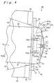
- Continuous cutting edge 52 is formed at the leading edge of blade 51, a positioning hole 54 for engaging with positioning pin 37 is formed at the middle of the leading edge, and a pair of oval holes 55 opposed to detecting ends 102 of detection means 26 is formed inset from said leading edge.
- Cutting edge 52 is formed perpendicular to both front and back sides of blade 51, i.e., parallel to the cutting direction (Fig. 3). More specifically, the perpendicularly-ground leading edge of blade 51 is cutting edge 52, and the corner where this leading edge and the back of blade 51 intersect forms edge 52a of cutting edge 52.
- cutting edge 52 comprises right and left curved blade members 61 at the place where the corners of tape T are cut, first guide blade member 62 joining the two curved blade members 61, and right and left second guide blade members 63 extending to the outside from the corresponding curved blade members 61.
- the plane shape that is the shape of edge 52a of curved blade members 61 comprises curved members 61a having a central angle of sixty degrees, and straight members 61b extending from both ends of curved members 61a tangentially to the curve.
- the radius of curved members 61a in this embodiment is preferably 3 mm.
- the angle between the side of the cut tape T and the corresponding straight member 61b is thus fifteen degrees, and the angle between the end (leading edge) of tape T and the other straight member 61b is also fifteen degrees.
- the central angle of curved members 61a shall preferably be set between fifty degrees and seventy degrees, inclusive.
- first guide blade member 62 is an arc following the leading edge of the arc-shaped stopper 36 and leading to the corresponding inside ends of curved blade members 61.
- the plane shape of each second guide blade member 63 leads from one end thereof to straight member 61b of curved blade member 61, and curves to a right angle perpendicular to tape insertion path 21.
- moving blade 42 similarly has an L-shaped cross section comprising blade 71 forming cutting edge 72, and blade holder 73 joined to blade 71.
- Moving blade 42 is fixed to stud 43 by blade holder 73 in a manner allowing moving blade 42 to pivot freely thereon.
- Moving blade 42 is also produced by stamping and then bending a stainless steel sheet, but the blade is not heat treated (hardened).
- the hardness of fixed blade 41 is greater than the hardness of moving blade 42.
- the sound of fixed blade 41 and moving blade 42 meshing together is therefore lower, and the cutting sound of the blades is not irritating.
- moving blade 42 wears with repeated cutting operations, but very little wear to fixed blade 41 occurs.
- Cutting edge 72 of moving blade 42 is shaped complementary to cutting edge 52 of fixed blade 41, and is perpendicular to the front and back faces of blade 71, i.e., to the direction of the cutting operation, similarly to fixed blade 41.
- Moving blade 42 is supported in a freely pivoting manner on stud 43 in the middle of the length of blade holder 73 such that the range of rotation is limited by drive apparatus 25.
- the axial center of stud 43 is positioned above blade 51 of fixed blade 41, and cutting edge 72 of moving blade 42 slides past cutting edge 52 of fixed blade 41 at an angle to the cutting direction.
- some part of cutting edge 72 of moving blade 42 is in constant contact with some part of cutting edge 52 of fixed blade 41 throughout the range of rotation, and the tape T is cut by moving the contact point from the stud 43 side forward.
- Stud 43 comprises a resin bushing 81 and a caulked pin 82 that functions as the rotational axis of moving blade 42.
- Fixed blade 41 and moving blade 42 are disposed on opposing sides of bushing 81, and are held together by pin 82 passing through fixed blade 41, moving blade 42, and bushing 81.
- Moving blade 42 is thus pressed toward fixed blade 41 in this state, or more specifically is pressed against fixed blade 41 via the bushing 81.
- a gap does not develop between cutting edge 72 of moving blade 42 and cutting edge 52 of fixed blade 41 even after moving blade 42 has worn noticeably, and a good cutting ability is retained in cutting blade 24.
- Drive apparatus 25 comprises drive motor 91, worm gear 93 fastened to output shaft 92 of drive motor 91, worm wheel 94 meshing with worm gear 93, and operating pin 95 projecting from worm wheel 94.
- Operating pin 95 engages with cut-out slot 74 in moving blade 42.
- Worm gear 93 and worm wheel 94 reduce the torque and speed of drive motor 91 while also changing the direction of rotation, and cause operating pin 95 to rotate around the rotational axis of worm wheel 94.
- Operating pin 95 and cut-out slot 74 in moving blade 42 form a positive motion cam causing moving blade 42 to rock by means of operating pin 95 rotating while sliding along cut-out slot 74.
- the frequency of moving blade 42 reciprocation is preferable set to approximately one second.
- Driving drive motor 91 is controlled by control means 27 in accordance with a detection signal input from detection means 26, which detects insertion of tape T to tape insertion path 21.
- detection means 26 is located in hollow 38 of guide means 23, and comprises switch arm 101 and detection switch 103. Detecting end 102 of switch arm 101 faces tape insertion path 21, and detection switch 103 contacts the lower end of switch arm 101. Switch arm 101 is further fastened to guide means 23 at the top of the inside hollow 38 in a manner allowing switch arm 101 to rotate freely between a non-detection position and a detection position. In the non-detection position detecting end 102 obstructs tape insertion path 21, and in the detection position is retracted from tape insertion path 21.
- Detection switch 103 may be, for example, a microswitch with switch lever 104 thereof in contact with the lower end of switch arm 101 and pushing switch arm 101 toward the non-detection position. Detection switch 103 is thus OFF when switch arm 101 is in the non-detection position, and becomes ON when switch arm 101 is rotated from the non-detection position to the detection position. Detection switch 103 continuously outputs the detection signal when in the ON state.
- Detecting end 102 of switch arm 101 splits the top end of switch arm 101 into two parts, forming a pair of detector projections 102a and 102b each disposed in a direction projecting into tape insertion path 21.
- the pair of detector projections 102a and 102b is provided before stopper 36 in the insertion direction, and are exposed through the pair of guide holes 39 formed in guide means 23 to oppose the leading edge of the tape T as it is inserted to tape insertion path 21.
- the pair of guide holes 39 match the pair of oval holes 55 formed in fixed blade 41, and permit the ends of detector projections 102a and 102b to enter oval holes 55 as detector projections 102a and 102b rotate to the non-detection position.
- detecting end 102 of detection means 26 comprises a pair of detector projections 102a and 102b, it is not necessary to provide a large opening for detecting end 102 in guide means 23 and fixed blade 41, and the mechanical strength of end 33 of guide means 23 and blade 51 of fixed blade 41 is not impaired.
- L1 is the distance between the outside edges of both detector projections 102a and 102b
- L2 is the distance between the inside edge of one detector projection 102a and the nearest side wall 32
- L3 is the distance between the inside edge of the other detector projection 102b and the other side wall 32
- the plane positions of the pair of detector projections 102a and 102b are set such that L2 equals L3, and L1, L2, and L3 are each less than the width of the narrowest usable tape T (9 mm wide in this example).
- switch arm 101 When thus comprised, switch arm 101 will rotate to the detection position and turn detection switch 103 ON irrespective of where in the widthwise direction of tape insertion path 21 tape T is inserted, even if the tape T is of the narrowest usable tape width. In addition, if the inserted tape T is less than the maximum width and is moved horizontally across tape insertion path 21, switch arm 101 will remain in the detection position, and detection switch 103 will remain in the ON state.
- the detection signal is in this embodiment output continuously while detection switch 103 is ON (for a maximum five seconds as described below), and moving blade 42 thus continues the reciprocating action relative to fixed blade 41.
- moving blade 42 starts to rotate from a position below fixed blade 41
- moving blade 42 slides across fixed blade 41 from below and cuts the corners of tape T.
- moving blade 42 bends the corners of tape T as it passes fixed blade 41, and then cuts tape T as it then rotates up.
- tape T is reliably cut irrespective of from where moving blade 42 starts to move, i.e., irrespective of where moving blade 42 stops. This means that it is not necessary to control the stop position of moving blade 42.
- a photointerrupter may be used in place of detection switch 103. More specifically, an optical sensor can be used in place of a mechanical switch to detect insertion of tape T to tape insertion path 21. In this case, the structure of detection means 26 can be further simplified.
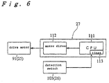
- Control means 27 comprises CPU 111 and motor drive circuit 112 as shown in Fig. 6.
- CPU 111 controls and drives drive motor 91 through motor drive circuit 112. More specifically, when tape T is inserted to tape insertion path 21, drive motor 91 starts, and when tape T is removed, drive motor 91 stops.
- CPU 111 also comprises timer 113 for counting a predetermined period, preferably five seconds in this embodiment, from the start of drive motor 91 operation. When this period elapses, CPU 111 overrides the detection signal from detection switch 103 and stops drive motor 91. This prevents overheating of drive motor 91 if foreign matter becomes trapped, and prevents unnecessary power consumption.
- the procedure executed by CPU 111 to control drive motor 91 is described below with reference to the flow chart in Fig. 7.
- the first step (S1) is to reset CPU 111 timer 113 to zero.
- a determination is then made in step S2 whether tape T is inserted to tape insertion path 21. If the tape T is not inserted, step S2 loops back and CPU 111 thus continuously checks for tape T insertion.
- CPU 111 starts drive motor 91 by means of motor drive 112 (S3), and in step S4 timer 113 starts counting. It is then determined whether tape T has been removed from tape insertion path 21 in step S5. If tape T has been removed, (step S5 returns NO), drive motor 91 in step is stopped S7.
- tape end trimming apparatus 20 The operation of tape end trimming apparatus 20 according to the present embodiment of the invention is described briefly below with reference to Fig. 5.
- Tape T is depressed by finger S as it is inserted to tape insertion path 21 guided by one side wall 32.
- tape T is positioned by said side wall 32 and stopper 36, and one of the leading corners is cut.
- tape T is slid horizontally to the other side wall 32.
- the tape T is thus positioned by said other side wall 32 and stopper 36, and the other comer is cut. Note that this is the operation used to cut both comers of a tape Tb narrower than the greatest possible tape width Ta.
- a tape of the greatest width Ta is fully inserted to tape insertion path 21, it is positioned by both side walls 32 and stopper 36, and both comers are simultaneously cut to shape.
- both comers of tape T can be cut to shape by simply inserting tape T to tape insertion path 21 to cut one comer and then sliding it horizontally to cut the other comer. It is therefore possible to efficiently cut both comers of tapes T of various widths using a single cutting blade 24.
- a second embodiment of a tape end trimming apparatus is described below with reference to Figs. 8 and 9.
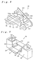
- a path width adjusting mechanism 121 as shown in Fig. 9, for adjusting the width of tape insertion path 21 is built in to guide means 23, and cutting blade 122, as shown in Fig. 8, is shaped to be able to simultaneously cut both leading edge comers of tapes T of various widths.
- Path width adjusting mechanism 121 comprises a pair of right and left adjustment tabs 123, a matching pair of right and left moving blocks 124 moving in conjunction with adjustment tabs 123, and an internal linkage mechanism (not shown in the figures) connecting the two moving blocks 124 to each other.
- Each adjustment tab 123 projects above the top of guide means 23, and is disposed in guide means 23 in a manner permitting both adjustment tabs 123 to slide freely therein.
- the base ends of adjustment tabs 123 are fastened to the corresponding moving blocks 124, and the exposed ends of moving blocks 124 move into and out of tape insertion path 21 through openings formed in side walls 32 to effectively adjust the width of tape insertion path 21.
- the internal linkage mechanism is, for example, an X-shaped linkage of which the ends are engaged with moving blocks 124, thus linking the movement of moving blocks 124 operated by adjustment tabs 123 such that both moving blocks 124 simultaneously move into or retract from the insertion path.
- the path width adjusted by the right and left moving blocks 124 is changed relative to the center line of tape insertion path 21.
- Cutting blade 122 comprises fixed blade 125, moving blade 126, and stud 127 similarly to the cutting blade of the first embodiment.
- Cutting edge 131 is symmetrically shaped in stages corresponding to plural tapes T of different widths.
- cutting edge 131 is formed for tapes T of three possible widths, and comprises right and left first cutting edges 131a for cutting both corners of tape T1 of the greatest possible width, right and left second cutting edges 131b for cutting both corners of tape T2 of an intermediate width, and right and left third cutting edges 131c for cutting both corners of tape T3 of the narrowest width.
- Cutting edges 131a, 131b, and 131c are formed in this example in sequential stages bulging out towards the center as shown in Fig. 8.
- FIG. 8 Of course, as will be appreciated by one of ordinary skill in the art, while in this example three different widths were shown, other numbers of widths are also contemplated.
- Cutting edge 132 of moving blade 126 is shaped complementary to cutting edge 131 of fixed blade 125.
- Moving blade 126 and fixed blade 125 are furthermore disposed with the center line of cutting edge 131 of fixed blade 125 and the center line of cutting edge 132 of moving blade 126 is aligned with the center line of tape insertion path 21.
- a regulated position adjusting mechanism for controlling the insertion position of the tape T according to the tape width is also provided in guide means 23 facing tape insertion path 21.
- This regulated position adjusting mechanism positions the tape T1 of the greatest width to first cutting edge 131a of fixed blade 125, positions tape T2 of the intermediate width to second cutting edge 131b, and positions tape T3 of the narrowest width to third cutting edge 131c.
- the regulated position adjusting mechanism preferably comprises a stopper or similar member projecting into tape insertion path 21 and moving in conjunction with the movement of moving blocks 124.
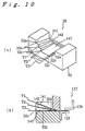
- the third and fourth embodiments of the present invention are described below with reference to Figs. 10A, 10B, 11A and 11B.
- the cutting blades and regulated position adjusting mechanisms of these embodiments are identical to those of the second embodiment described above, and the following description is therefore limited to the structures of the insertion paths, which differ from that of the second embodiment.
- the right and left side walls 32 of guide means 23 are formed in steps descending toward the inside of the insertion path, thus forming at the top step a pair of side walls 32a forming a first tape insertion path 141 for a tape T1 of the greatest width, forming at the middle step a pair of side walls 32b forming a second tape insertion path 142 for a tape T2 of intermediate width, and forming at the bottom step a pair of side walls 32c forming a third tape insertion path 143 for a tape T3 of the narrowest width.
- first tape insertion path 141 slope towards fixed blade 125 so that the leading edge of the tape T will be appropriately directed to cutting blade 122 by the corresponding tape insertion path 141, 142, or 143.
- a first tape insertion path 151 for the narrowest tape T3 is formed as the top slot in the face of guide means 23
- second tape insertion path 152 for tape T2 of an intermediate width is formed as the middle slot
- third tape insertion path 153 for tape T3 of the greatest width is formed as the bottom slot in guide means 23.
- the first, second, and third tape insertion paths 151 and 152 curve as they extend toward fixed blade 125.
- cutting blade 161 comprises a pair of right and left presser blades 162, and cutter bar 163 against which presser blades 162 press.
- Each presser blade 162 has a curved cutting edge similar to curved blade members 61 of the first embodiment, and is fastened to the bottom of block-shaped cutter holder 164.
- Cutter holder 164 is pushed upward by a spring or other means, and is supported by a guide member allowing cutter holder 164 to move vertically (note that neither spring nor guide member is shown).
- Plate cam 165 contacts the top of cutter holder 164, and cam shaft 166 of plate cam 165 is connected to a motor (not shown in the figure). When the motor drives plate cam 165, drive cutter holder 164 moves down against the force of the spring.
- presser blade 162 presses against and cuts the corners of tape T positioned on cutter bar 163, thus shaping the corners.
- Cutter bar 163 is also provided as an extension of tape insertion path 21, and thus also functions as part of tape insertion path 21.
- Cutter bar 163 also comprises right and left side walls 167 and end stopper wall 168, which position tape Ta of the greatest usable width and enable both corners thereof to be cut at the same time.
- a tape Tb (not shown in the figure) narrower than tape Ta is positioned by one side wall 167 and stopper wall 168 to cut one corner, and is then positioned by the other side wall 167 and stopper wall 168 to cut the other corner.
- a rubber pad or similar member may also be provided on the top of cutter bar 163.
- the structure of cutting blade 161 is also simpler. Furthermore, if the position of cam shaft 166 of plate cam 165 can be adjusted up and down, it is also possible to cut only the adhesive-backed film part of a tape T backed by a backing paper, thereby both shaping the tape T as desired and facilitating removal of the backing paper.
Landscapes
- Life Sciences & Earth Sciences (AREA)
- Forests & Forestry (AREA)
- Engineering & Computer Science (AREA)
- Mechanical Engineering (AREA)
- Handling Of Sheets (AREA)
- Nonmetal Cutting Devices (AREA)
- Processing Of Meat And Fish (AREA)
- Surgical Instruments (AREA)
- Details Of Cutting Devices (AREA)
- Auxiliary Devices For And Details Of Packaging Control (AREA)
Description
- The present invention relates to a tape end trimmer for cutting the comers of the ends of a printed label-like tape in a radius or other shape.
- Tape printing apparatus are commonly used to print letters and/or graphics on a blank tape. The blank tape is fed to the tape printing apparatus, and the printed tape is cut and then trimmed by a tape end trimmer. One type of conventional tape end trimmer known is utilized in the tape printing apparatus and described in Japanese JP-A-3-287397/1991. This type of tape printing apparatus comprises a trimmer for the specific width of the tape to be cut, and requires the trimmer to be changed each time a tape having different width is used. The trimmer comprises a cutter unit for trimming the tape end, and a guide member for guiding the inserted tape to the cutter unit. When printing is completed, the tape fed out from the tape printing apparatus is inserted into the trimmer, and the end of the tape is cut automatically by the trimmer.
- Trimming the tape end by the cutter unit is accomplished in this case by the cutter unit simultaneously cutting both comers of the tape end and the edge connecting those comers. More specifically, the end of the tape is cut to a known dimension so that the comers of the resulting tape end are curved.
- EP-A-0 449 465 discloses a tape end trimming apparatus according to the pre-characterizing portion of
claim 1, in which the abutment surface of the end abutment means is displaced forward in the tape insertion direction relative to the cutting plane, so that in this prior art, like in the one discussed above, both comers of the tape end and the edge connecting those comers are simultaneously cut. - These conventional tape end trimmers, thus, simultaneously cut not only the comers of the tape end, but the edge member connecting those comers, i.e., cut the tape end to a constant dimension. The overall length of the tape is therefore shortened by the amount cut off, and a long blank (unprinted) space at the tape end must be reserved to prevent the printed area from being cut off. This results in excessive tape waste.
- Furthermore, the trimmer itself must be manufactured according to the tape width, and cannot be used to cut tapes of any other width. With a tape printing apparatus of this type, therefore, it is necessary to have plural trimmers to print and cut tapes of different widths, thus making the tape trimming operation more complex and cumbersome.
- Therefore it is an object of the present invention to obviate the aforementioned problems associated with convention tape and trimmers and to provide a tape end trimmer for appropriately cutting and shaping the ends of plural tapes having different widths without wasting excessive amount of tape and without requiring replacement of the cutting blade according to the tape width.
- It is a further object of the present invention to provide a tape end trimmer for cutting and shaping tapes of plural different widths using a single cutting blade without wasting tape and with an appropriate and simple operation.
- It is an additional object of the present invention to provide a tape end trimmer which can be built compactly even when the apparatus can handle wide tapes.
- It is still an object of the present invention to provide a tape end trimmer having a single cutting blade for trimming, tapes of different widths can be appropriately cut and shaped by simply inserting the tape.
- These objects are achieved with tape end trimming apparatus as claimed in
claim 1 and its particular embodiments as claimed in the dependent claims. - According to the claimed solution, the insertion position of the tape is determined by the end abutment means when the tape is inserted into the insertion path with at least one side abutting against the receptive lateral abutment means. More specifically, provided the tape width is smaller than the width of the insertion path, when the cutting blade of the cutting means is operated to cut the tape with one side of the tape positioned by the one lateral abutment means and the end of the tape positioned by the end abutment means, one end comer of the tape is cut to shape. When the tape is then removed and reinserted with the other side of the tape positioned by the other lateral abutment means, or is simply moved horizontally to position the other side of the tape to the other lateral abutment means without completely removing the tape from the insertion path, and the cutting blade of the cutting means is again operated, the other end comer of the tape is cut to shape. By thus using both sides and the end of the tape to position the tape, and then operating the cutting means, both comers of the tape end can be cut to the desired shape using a single cutting blade irrespective of the actual tape width. Because an imaginary plane comprising said end abutment surface intersects with a cutting edge of the cutting blade means at two positions on opposite sides of said longitudinal axis, the comers of the tape end can be trimmed without trimming the edge of tape connecting those corner at the same time.
- With the configuration according to
claim 2, the tape can be easily positioned for cutting the other corner by simply moving the tape horizontally to the other parallel side after cutting the first corner. - When the distance between the pair of passage walls matches the width of the tape of the greatest width that may be shaped and cut, both sides of the tape of the greatest insertable width can be automatically positioned at the same time by simply inserting the tape to the insertion path guided by the path walls, i.e. by simply inserting the tape, and both comers can be simultaneously cut with a single cutting action.
- As a result of the arrangement according to
claim 4, the central angle of the curve is smaller than ninety degrees with this configuration, the sides and end of the tape are cut at an angle by the part of the cutting blade forming the tangential lines. Accordingly, the cut ends are cut cleanly, and the corners can be accurately cut to a curved shape even without the tape being accurately positioned. - Furthermore, because the central angle of the curve is from fifty to seventy degrees, the cut end is not visually inferior when compared with a curved shape having a precise ninety degree central angle, and a pleasing cut finish can be obtained.
- In accordance with
claim 5 the tape is cut by means of a pressure cutting action with pressure applied from both front and back sides of the tape. Cutting resistance is therefore low, and the tape can be cut with a relatively low cutting force. Furthermore, because the fixed blade is disposed to the guide means, the tape comers can be consistently cut to a constant, accurate shape by positioning the tape corners to the cutting edge of the fixed blade. - When, in accordance with
claim 6, the plate-like blade forming the cutting edges of the fixed and moving blades are formed perpendicularly to and integrally with the respective plate-like blade holders, the fixed and moving blades can be formed by bending a sheet material, and the rigidity of both can be improved. - In accordance with the configuration of
claim 7, the member pressing on the end of the inserted tape can be formed to incorporate the cutting blade of the fixed blade. - In accordance with
claim 8, even when the end of the tape is curled, this configuration makes it difficult for the cutting blade of the fixed blade to obstruct insertion of the tape, effectively straightens any curling in the fully inserted tape, and introduces the leading edge of the tape to the cutting blade in a flattened state. Narrowing of the insertion path also prevents insertion of tape too thick for the cutting blades to cut because the tape will bind in the insertion path before the blade. - In accordance with claim 9 the cutting operation can be accomplished using the moving blade as a lever, and the structure of the cutting means can thus be simplified.
- In accordance with
claim 10 the tape can be cut using a scissors-like cutting operation in which the one cutting blade is fixed, and the moving blade can be assembled with good precision relative to the fixed blade. Furthermore, the shaft member positions the fixed blade to the moving blade with good precision, and the fixed blade can be assembled to the guide means while thus assembled. - In accordance with
claim 11 the tape is cut by means of a three-dimensional cutting action, i.e., the contact point of the cutting edge of the moving blade moves along the cutting edge of the fixed blade during the cutting operation. As a result, the cutting resistance is low, and the tape can be appropriately cut with little force. - In accordance with
claim 12 the shape of the cutting edges is retained and the cutting ability does not deteriorate even after the cutting edges of the fixed and moving blades wear as a result of repeated cutting operations. - In accordance with claim 13, when the cutting operation is repeated many times, the cutting edge of the moving blade wears more rapidly than does the cutting edge of the fixed blade, and the fixed blade retains its original shape. As a result, if the tape is positioned to the cutting edge of the fixed blade, the cutting position of the tape will not change as a result of wear to the cutting edge.
- In accordance with claim 14, when the cutting edge of the moving blade wears, a gap does not occur between the fixed and moving blades, and a good cutting edge can be maintained for an extended period of time.
- In accordance with claim 15 it is possible to automatically cut and shape the end of the inserted tape.
- In accordance with claim 16 the cutting operation of the moving blade is executed to automatically cut and shape the tape comers when the tape is simply inserted into the insertion path. In addition, the cutting operation of the moving blade terminates automatically when the tape is removed from the insertion path.
- As a result of the configuration of claim 17, the cutting operation of the moving blade executes for as long as the tape is inserted into the insertion path. It is therefore possible for the tape to be cut while it is being positioned, and the tape comers can be reliably cut to the desired shape. In addition, the tape will be reliably cut irrespective of where the cutting start position of the moving blade is located. More specifically, it is not necessary to control the stop position of the moving blade.
- In accordance with claim 18, the cutting operation of the moving blade is sustained i.e., is repeatedly executed, when the tape is inserted, but stops automatically if the tape is not removed after being cut and a predetermined period of time elapses. This effectively suppresses unnecessary operation of the moving blade.
- In accordance with claim 19, the cutting operation of the moving blade starts before the tape end reaches the end position regulating means. The tape can therefore be cut and shaped quickly, and the tape comers can be gradually cut to the particular curved shape. The placement of the detection means also prevents the tape end from being obstructed by the stopped moving blade before it reaches the end position regulating means.
- In accordance with
claim 20 detection errors or non-detection by the detection means caused by dust, lint, or other foreign matter can be prevented, and tape insertion can be reliably detected. - In accordance with
claim 21, the switch arm will not interfere with insertion of the tape, and the switch body can be positioned with a greater degree of freedom. - By virtue of the feature of
claim 22 it is not necessary to increase the size of the detecting end of the switch arm as a means of improving detection precision, and it is also not necessary to provide a large hole for the detecting end of the switch arm in the guide means forming the insertion path. In addition, both detector projections can operate under identical detection conditions. - With the configuration according to
claim 23, the detector projections can reliably detect tape insertion and accomplish the cutting operation irrespective of where in the insertion path a tape of the narrowest usable width is inserted. As a result, moving the tape sideways for positioning after insertion to the insertion path will not interfere with tape cutting. Furthermore, if the tape is moved sideways to cut the second comer after cutting the first comer, the cutting blades will not stop operating and tape cutting can be continuously accomplished. - The embodiment according to
claim 24 makes it possible to only partially cut the tape by appropriately adjusting the cutting depth of the presser blade. More specifically, when the tape comprises an adhesive-backed tape and a backing paper to be removed for applying the tape to some object, it is possible to cut only the adhesive-backed tape part of said tape, and the tape can thus be both cut to the desired shape and processed to facilitate separation of the adhesive-backed tape and the backing paper. - In accordance with another embodiment of the present invention, a cutting means is provided for cutting the comers of a tape end to a known shape and guide means is disposed in proximity to the cutting means, comprising an insertion path for guiding the inserted tape to the cutting means. An end abutment means determines the insertion position of the end of the tape inserted into the insertion path, and a pair of lateral abutment means determines the insertion positions of both sides of the tape inserted into the insertion path. The cutting means comprises a first cutting blade for trimming the comer of one side of the tape end with the position of the side of the tape regulated by one lateral abutment means and the position of the tape end regulated by the end position regulating means, and a second cutting blade for trimming the comer of the other tape side with the position of the other side of the tape regulated by the other lateral abutment means and the position of the end thereof regulated by the end position regulating means.
- The first and second comers of the tape end are thus separately cut by the first and second cutting blades, enabling a more compact construction around the cutting blades, and making it possible to prevent a cutting apparatus usable with wide tapes from becoming overly large.
- In the embodiment according to
claim 25, when the tape is inserted into the insertion path after adjusting the path width adjusting mechanism to the width of the tape to be cut, the tape is controlled to the insertion position appropriate to that tape width by the position adjusting mechanism. As a result, the tape end is appropriately positioned, and when the cutting blade is operated, one part of the cutting edge of the cutting blade simultaneously cuts and shapes both comers of the tape. By thus enabling the width of the insertion path to be adjusted for various tape widths, and shaping the cutting blade to simultaneously cut both comers of tapes of different widths, it is possible to appropriately cut and shape tapes of different widths using a single cutting blade. - In the embodiment according to
claim 25, when a tape is inserted into the insertion path of the matching width in an apparatus of this configuration, the tape is controlled to the insertion position matching that tape width by the position adjusting mechanism. As a result, the tape end is appropriately positioned, and when the cutting blade is operated, one part of the cutting edge of the cutting blade simultaneously cuts and shapes both comers of the tape. By thus providing plural insertion paths according to the various tape widths that may be used, and shaping the cutting blade to simultaneously cut both comers of tapes of different widths, it is possible to appropriately cut and shape tapes of different widths using a single cutting blade. - Other objects and attainments together with a fuller understanding of the invention will become apparent and appreciated by referring to the following description of preferred embodiments and claims taken in conjunction with the accompanying drawings in which like reference symbols refer to like parts and in which:
- Fig. 1
- is an overview of a tape printing apparatus equipped with a tape end trimming apparatus in accordance with the present invention;
- Fig. 2
- is an exploded perspective view of the tape end trimming apparatus in accordance with a first embodiment of the present invention;
- Fig. 3
- is a cross-sectional view of the tape end trimming apparatus according to the first embodiment of the present invention taken along line A-A in Fig. 2;
- Fig. 4
- is a plan view in the vicinity of a fixed blade in the tape end trimming apparatus in accordance with the first embodiment of the present invention;
- Fig. 5
- is a plan view in the vicinity of a tape insertion path in the tape end trimming apparatus in accordance with the first embodiment of the present invention;
- Fig. 6
- is a block diagram of a control system of the tape end trimming apparatus in accordance with the first embodiment of the present invention;
- Fig. 7
- is a flow chart of the control system of the tape end trimming apparatus in accordance with the first embodiment of the present invention;
- Fig. 8
- is an overview of the cutting blade in a tape end trimming apparatus in accordance with a second embodiment of the present invention;
- Fig. 9
- is an overview in the vaccinate of a tape insertion path in a tape end trimming apparatus in accordance with the second embodiment of the present invention;
- Fig. 10A
- is an overview and Fig. 10B is a cross-sectional view in the vicinity of the tape insertion path in a tape end trimming apparatus in accordance with a third embodiment of the present invention;
- Fig. 11A
- is an overview and Fig. 11B is a cross-sectional area in the vicinity of a tape insertion path in a tape end trimming apparatus in accordance with a fourth embodiment of the present invention; and
- Fig. 12
- is a perspective view of a tape end trimming apparatus in accordance with a fifth embodiment of the present invention.
- The preferred embodiments of a tape end trimming apparatus according to the present invention is described hereinbelow with reference to the accompanying figures as applied to a tape printing apparatus. As noted above the tape printing apparatus is used to print letters and/or graphics to a blank tape, and then to cut the printed tape to a predetermined dimension to form labels. The tape end trimming apparatus then cuts and shapes the corners of the ends of this tape label to a particular curved shape.
- An example of a
tape printer 1 is shown in Fig. 1.Tape printer 1 comprisescase 3 havinggrip 2 formed at the front thereof.Keyboard 4 is provided in the front half ofcase 3, the back half of which is enclosed bycover 5, which can be opened and closed.Tape cartridge 6, a printing mechanism (not shown in the figure), anddisplay 7 are exposed by openingcover 5 to expose the inside ofcase 3. - Typically the user inputs the letters to be printed using
keyboard 4 while viewing the text ondisplay 7 through window 9, and presses a print key onkeyboard 4 after confirming the input text to print to the tape. When the print key is pressed, the printer mechanism feeds tape T fromtape cartridge 6 and prints, and feeds the printed tape T out fromcase 3. -
Secondary case 10 is disposed at the side ofcase 3, and comprises tape opening 11 through which the fed tape T passes.Cutter button 12 is provided insecondary case 10 behindtape opening 11. When printing is completed, the tape T being fed through tape opening 11 stops. Ifcutter button 12 is then pressed, the tape cutter is operated via a link (neither being shown in the figures), and the end of tape T is cut squarenear tape opening 11. - Also disposed in
secondary case 10 in front oftape opening 11 aretape insertion path 21 of tapeend trimming apparatus 20 forming the essential component of the present invention, andtape insertion opening 22 adjoiningtape insertion path 21. Tape Ta in Fig. 1 indicates the maximum tape width that can inserted totape insertion opening 22. When the end of maximum-width tape Ta is inserted totape insertion opening 22, both corners of the leading edge of tape Ta are cut to the defined shape, such as a curved shape. Tape Tb in Fig. 1 indicates a tape having a width narrower than the maximum width Ta that can also be inserted totape insertion opening 22. When the end of tape Tb is inserted totape insertion opening 22, only one corner is cut to shape each time the tape Tb is inserted. - The tape T used in this embodiment is an adhesive film tape with a backing paper. The tape printer prints only to the front of the adhesive film tape. This tape is applied to the desired object after cutting all four corners of the tape to shape and removing the backing paper. Tape T may also be available in various widths, e.g., 24 mm, 18 mm, 12 mm, and 9 mm, in which case
plural tape cartridges 6 holding blank tapes of the same widths (24 mm, 18 mm, 12 mm, and 9 mm) are also available. In other words, aseparate tape cartridge 6 is provided for each usable tape width, and to print a tape of a specific width the user must install a tape cartridge containing that width of tape. - Tape
end trimming apparatus 20 is described in detail below with reference to Fig. 2. As shown in Fig. 2, tapeend trimming apparatus 20 comprises guide means 23 formingtape insertion path 21 andtape insertion opening 22; cuttingblade 24 provided at the end of guide means 23; and driveapparatus 25 for operating cuttingblade 24. Detection means 26 for detecting insertion of tape T totape insertion path 21 is provided in guide means 23, and is connected to control means 27 ofdrive apparatus 25. In this case, guide means 23 is disposed on the outside of the tape end trimming apparatus (Fig. 1), and the other components are built in tocase 3. - Guide means 23 is disposed to fit from the side of
case 3 intosecondary case 10 projecting at the side of case 3 (Fig. 1), and comprises on the top thereof a shallow channel-liketape insertion path 21, which is formed bypassage surface 31 and a pair ofside walls 32. The pair ofside walls 32 rise substantially perpendicular from theflat passage surface 31, and are formed parallel to each other with a gap therebetween set according to the maximum width (24 mm in this example) of tape Ta.Side walls 32 together form the guide members guiding the sides of the inserted tape T, and thus form the lateral abutment means controlling the positions of the sides of the tape T for cutting. Note that in this example the gap between the sides oftape insertion path 21 is 24.1 mm to accommodate a maximum tape Ta width of 24 mm. - By inserting the maximum width tape Ta with both sides guided by the pair of side walls 32 (i.e., simply inserting the tape to tape insertion path 21), both comers at the leading edge of tape Ta are cut to the desired shape. When a tape of narrower width Tb (18 mm, 12 mm, or 9 mm in this case) is inserted with one side thereof guided by one of the
side walls 32, only the one leading comer of tape Tb is cut to shape; the other leading corner is then cut by inserting the tape Tb with the side of the uncut comer guided by theother side wall 32. It is to be noted that it is also possible to simply insert tape Tb to tapeinsertion path 21, then slide it horizontally to the oneside wall 32 to cut the one comer, and then slide it horizontally to theother side wall 32 to cut the other comer. It is also possible to insert tape Tb with one side thereof guided by oneside wall 32, cut the comer, and then slide the tape Tb to theother side wall 32 to cut the other comer. - A pair of
supports 34 is also provided in a vertical orientation on opposing sides oftape insertion path 21 atend 33 of guide means 23 at the side ofcase 3.Fixed blade 41 of cuttingblade 24, described below, is fastened using a pair ofset screws 35 to this pair of supports 34. In this position,blade 51 of fixedblade 41, described below, covers the end oftape insertion path 21 from above. More specifically, end 33 of guide means 23 forming the end oftape insertion path 21 is set back slightly fromblade 51 of fixedblade 41, and projects conforming to the shape of the edge ofblade 51. A crescent-shapedstopper 36, or end abutment means, projects upward at the top of thisshaped end 33 of guide means 23. Positioningpin 37 projects at the top ofstopper 36.Blade 51 of fixedblade 41 is fit to thispositioning pin 37, and fixedblade 41 is thus positioned totape insertion path 21. - In this case, positioning
pin 37 is positioned on the center line oftape insertion path 21, andstopper surface 36a ofstopper 36 extends symmetrically to said center line perpendicular totape insertion path 21. As a result, when a narrow tape Tb is inserted, the end of tape Tb will contactstopper 36, and the insertion position of the end of this tape Tb will be reliably controlled. The tape T inserted totape insertion path 21 is thus positioned bystopper 36 andside walls 32. - In addition, as shown in Fig. 3,
passage surface 31 oftape insertion path 21 rises slightly nearstopper 36. As described above,blade 51 of fixedblade 41 is disposed in opposition topassage surface 31. In addition, the gap betweenpassage surface 31 andblade 51 is large at the outside and gradually narrows at the inside in the insertion direction. In other words, there is a sufficiently large gap in the area oftape insertion opening 22 while the gap at the inside end oftape insertion path 21 is only slightly greater than the thickness of the tape T. This makes it easy to insert the tape T to thetape insertion path 21, and depresses the tape T to hold it flat as the tape T is inserted tostopper 36. - Referring back to Fig. 2, cutting
blade 24 comprises fixedblade 41, movingblade 42, and stud 43 linking fixedblade 41 and movingblade 42, thus forming a scissors-like construction for cutting the tape T by a scissors action. Movingblade 42 pivots on stud 43, crossing while contacting fixedblade 41 from the bottom up to cut tape T. Fixedblade 41 has an L-shaped crosssection comprising blade 51 formingcutting edge 52, andblade holder 53 joined toblade 51.Fixed blade 41 is fixed to guide means 23 byblade holder 53. In this case, fixedblade 41 is produced by, for example, stamping and then bending a stainless steel sheet, heat treating (hardening) the blade, and then grinding or polishing thecutting edge 52. -
Continuous cutting edge 52 is formed at the leading edge ofblade 51, apositioning hole 54 for engaging withpositioning pin 37 is formed at the middle of the leading edge, and a pair ofoval holes 55 opposed to detectingends 102 of detection means 26 is formed inset from said leading edge. Cuttingedge 52 is formed perpendicular to both front and back sides ofblade 51, i.e., parallel to the cutting direction (Fig. 3). More specifically, the perpendicularly-ground leading edge ofblade 51 is cuttingedge 52, and the corner where this leading edge and the back ofblade 51 intersectforms edge 52a of cuttingedge 52. - As shown in Fig. 4, cutting
edge 52 comprises right and leftcurved blade members 61 at the place where the corners of tape T are cut, firstguide blade member 62 joining the twocurved blade members 61, and right and left secondguide blade members 63 extending to the outside from the correspondingcurved blade members 61. - The plane shape that is the shape of
edge 52a ofcurved blade members 61 comprisescurved members 61a having a central angle of sixty degrees, andstraight members 61b extending from both ends ofcurved members 61a tangentially to the curve. The radius ofcurved members 61a in this embodiment is preferably 3 mm. The angle between the side of the cut tape T and the correspondingstraight member 61b is thus fifteen degrees, and the angle between the end (leading edge) of tape T and the otherstraight member 61b is also fifteen degrees. By thus defining the central angle ofcurved members 61a as less than ninety degrees, the corners of the tape T can be cut to a visually appealing curved shape even when the tape T is not precisely positioned to the cutting blade. It is to be noted that for the curved members to be visually appealing, the central angle ofcurved members 61a shall preferably be set between fifty degrees and seventy degrees, inclusive. - The plane shape of first
guide blade member 62 is an arc following the leading edge of the arc-shapedstopper 36 and leading to the corresponding inside ends ofcurved blade members 61. The plane shape of each secondguide blade member 63 leads from one end thereof tostraight member 61b ofcurved blade member 61, and curves to a right angle perpendicular totape insertion path 21. - Referring back to Fig. 2, moving
blade 42 similarly has an L-shaped crosssection comprising blade 71 formingcutting edge 72, andblade holder 73 joined toblade 71. Movingblade 42 is fixed to stud 43 byblade holder 73 in a manner allowing movingblade 42 to pivot freely thereon. Movingblade 42 is also produced by stamping and then bending a stainless steel sheet, but the blade is not heat treated (hardened). As a result, the hardness of fixedblade 41 is greater than the hardness of movingblade 42. The sound of fixedblade 41 and movingblade 42 meshing together is therefore lower, and the cutting sound of the blades is not irritating. In addition, movingblade 42 wears with repeated cutting operations, but very little wear to fixedblade 41 occurs. As a result, there is very little change in the cut shape of tape T, which is positioned to edge 52a of fixedblade 41, and the desired curved shape can be maintained. Moreover, because cuttingedges edges blade 24 does not deteriorate. Furthermore, as fixedblade 41 and movingblade 42 wear and adapt to each other, the meshing sound (cutting noise) decreases. Moreover, it is sufficient to heat treat only the area of cuttingedge 52 or only the area ofblade 51. In addition, when a carbide steel or hardened stainless steel is used, movingblade 42 may also be normalized. - Cutting
edge 72 of movingblade 42 is shaped complementary to cuttingedge 52 of fixedblade 41, and is perpendicular to the front and back faces ofblade 71, i.e., to the direction of the cutting operation, similarly to fixedblade 41. Movingblade 42 is supported in a freely pivoting manner on stud 43 in the middle of the length ofblade holder 73 such that the range of rotation is limited bydrive apparatus 25. The axial center of stud 43 is positioned aboveblade 51 of fixedblade 41, and cuttingedge 72 of movingblade 42 slides past cuttingedge 52 of fixedblade 41 at an angle to the cutting direction. In other words, some part of cuttingedge 72 of movingblade 42 is in constant contact with some part of cuttingedge 52 of fixedblade 41 throughout the range of rotation, and the tape T is cut by moving the contact point from the stud 43 side forward. - Stud 43 comprises a
resin bushing 81 and a caulkedpin 82 that functions as the rotational axis of movingblade 42.Fixed blade 41 and movingblade 42 are disposed on opposing sides ofbushing 81, and are held together bypin 82 passing through fixedblade 41, movingblade 42, andbushing 81. Movingblade 42 is thus pressed toward fixedblade 41 in this state, or more specifically is pressed against fixedblade 41 via thebushing 81. As a result, a gap does not develop between cuttingedge 72 of movingblade 42 and cuttingedge 52 of fixedblade 41 even after movingblade 42 has worn noticeably, and a good cutting ability is retained in cuttingblade 24. -
Drive apparatus 25 comprisesdrive motor 91,worm gear 93 fastened tooutput shaft 92 ofdrive motor 91,worm wheel 94 meshing withworm gear 93, and operatingpin 95 projecting fromworm wheel 94. Operatingpin 95 engages with cut-out slot 74 in movingblade 42.Worm gear 93 andworm wheel 94 reduce the torque and speed ofdrive motor 91 while also changing the direction of rotation, and causeoperating pin 95 to rotate around the rotational axis ofworm wheel 94. Operatingpin 95 and cut-out slot 74 in movingblade 42 form a positive motion cam causing movingblade 42 to rock by means of operatingpin 95 rotating while sliding along cut-out slot 74. In other words, whendrive motor 91 is driven, movingblade 42 reciprocates through a certain angle to cut tape T. It is to be noted that the frequency of movingblade 42 reciprocation is preferable set to approximately one second. - Driving
drive motor 91 is controlled by control means 27 in accordance with a detection signal input from detection means 26, which detects insertion of tape T totape insertion path 21. - Referring again to Fig. 3, detection means 26 is located in hollow 38 of guide means 23, and comprises
switch arm 101 anddetection switch 103. Detectingend 102 ofswitch arm 101 facestape insertion path 21, anddetection switch 103 contacts the lower end ofswitch arm 101.Switch arm 101 is further fastened to guide means 23 at the top of the inside hollow 38 in a manner allowingswitch arm 101 to rotate freely between a non-detection position and a detection position. In the non-detectionposition detecting end 102 obstructstape insertion path 21, and in the detection position is retracted fromtape insertion path 21. -
Detection switch 103 may be, for example, a microswitch withswitch lever 104 thereof in contact with the lower end ofswitch arm 101 and pushingswitch arm 101 toward the non-detection position.Detection switch 103 is thus OFF whenswitch arm 101 is in the non-detection position, and becomes ON whenswitch arm 101 is rotated from the non-detection position to the detection position.Detection switch 103 continuously outputs the detection signal when in the ON state. - Detecting
end 102 ofswitch arm 101 splits the top end ofswitch arm 101 into two parts, forming a pair ofdetector projections tape insertion path 21. The pair ofdetector projections stopper 36 in the insertion direction, and are exposed through the pair of guide holes 39 formed in guide means 23 to oppose the leading edge of the tape T as it is inserted totape insertion path 21. The pair of guide holes 39 match the pair ofoval holes 55 formed in fixedblade 41, and permit the ends ofdetector projections oval holes 55 asdetector projections - Thus, when tape T is inserted to
tape insertion path 21, the leading edge of tape T pushes back ondetector projections switch arm 101, andcontacts stopper 36. As a result,detection switch 103 becomes ON a moment before tapeT contacts stopper 36. It is therefore possible to gradually cut the corners of tape T to the desired curved shape. Furthermore, because detectingend 102 of detection means 26 comprises a pair ofdetector projections end 102 in guide means 23 and fixedblade 41, and the mechanical strength ofend 33 of guide means 23 andblade 51 of fixedblade 41 is not impaired. - If, as shown in Fig. 5, L1 is the distance between the outside edges of both
detector projections detector projection 102a and thenearest side wall 32, and L3 is the distance between the inside edge of theother detector projection 102b and theother side wall 32, the plane positions of the pair ofdetector projections switch arm 101 will rotate to the detection position and turndetection switch 103 ON irrespective of where in the widthwise direction oftape insertion path 21 tape T is inserted, even if the tape T is of the narrowest usable tape width. In addition, if the inserted tape T is less than the maximum width and is moved horizontally acrosstape insertion path 21,switch arm 101 will remain in the detection position, anddetection switch 103 will remain in the ON state. - It is to be noted that the detection signal is in this embodiment output continuously while
detection switch 103 is ON (for a maximum five seconds as described below), and movingblade 42 thus continues the reciprocating action relative to fixedblade 41. For example, when movingblade 42 starts to rotate from a position below fixedblade 41, movingblade 42 slides across fixedblade 41 from below and cuts the corners of tape T. However, when movingblade 42 starts to rotate from a position above fixedblade 41, movingblade 42 bends the corners of tape T as it passes fixedblade 41, and then cuts tape T as it then rotates up. As a result, tape T is reliably cut irrespective of from where movingblade 42 starts to move, i.e., irrespective of where movingblade 42 stops. This means that it is not necessary to control the stop position of movingblade 42. - It is to be noted that a photointerrupter may be used in place of
detection switch 103. More specifically, an optical sensor can be used in place of a mechanical switch to detect insertion of tape T totape insertion path 21. In this case, the structure of detection means 26 can be further simplified. - Control means 27 comprises
CPU 111 andmotor drive circuit 112 as shown in Fig. 6. When the detection signal is input fromdetection switch 103 toCPU 111,CPU 111 controls and drives drivemotor 91 throughmotor drive circuit 112. More specifically, when tape T is inserted totape insertion path 21, drivemotor 91 starts, and when tape T is removed, drivemotor 91 stops. -
CPU 111 also comprisestimer 113 for counting a predetermined period, preferably five seconds in this embodiment, from the start ofdrive motor 91 operation. When this period elapses,CPU 111 overrides the detection signal fromdetection switch 103 and stops drivemotor 91. This prevents overheating ofdrive motor 91 if foreign matter becomes trapped, and prevents unnecessary power consumption. - The procedure executed by
CPU 111 to controldrive motor 91 is described below with reference to the flow chart in Fig. 7. The first step (S1) is to resetCPU 111timer 113 to zero. A determination is then made in step S2 whether tape T is inserted totape insertion path 21. If the tape T is not inserted, step S2 loops back andCPU 111 thus continuously checks for tape T insertion. When tape T is inserted totape insertion path 21,CPU 111 starts drivemotor 91 by means of motor drive 112 (S3), and instep S4 timer 113 starts counting. It is then determined whether tape T has been removed fromtape insertion path 21 in step S5. If tape T has been removed, (step S5 returns NO), drivemotor 91 in step is stopped S7. If the tape T has not been not removed (S5 = YES) it is determined in step S6 whether five seconds have passed since tape T was inserted. If five seconds has elapsed (S6 = YES) then NO for 91 is also stopped in step S7. Otherwise the procedure returns to step S5. - The operation of tape
end trimming apparatus 20 according to the present embodiment of the invention is described briefly below with reference to Fig. 5. Tape T is depressed by finger S as it is inserted totape insertion path 21 guided by oneside wall 32. When tape T is fully inserted totape insertion path 21, tape T is positioned by saidside wall 32 andstopper 36, and one of the leading corners is cut. After confirming that the tape T has been cut based on the sound of cutting, tape T is slid horizontally to theother side wall 32. The tape T is thus positioned by saidother side wall 32 andstopper 36, and the other comer is cut. Note that this is the operation used to cut both comers of a tape Tb narrower than the greatest possible tape width Ta. When a tape of the greatest width Ta is fully inserted totape insertion path 21, it is positioned by bothside walls 32 andstopper 36, and both comers are simultaneously cut to shape. - As described above, both comers of tape T can be cut to shape by simply inserting tape T to
tape insertion path 21 to cut one comer and then sliding it horizontally to cut the other comer. It is therefore possible to efficiently cut both comers of tapes T of various widths using asingle cutting blade 24. - Though not specifically shown in the figures, it is also possible to handle tapes of even greater widths by providing a pair of right and left cutting
blades 24. In this case, the reciprocation range of each movingblade 42 can be reduced, and the overall tapeend trimming apparatus 20 can be built more compactly. - A second embodiment of a tape end trimming apparatus according to the present invention is described below with reference to Figs. 8 and 9. In this second embodiment, a path width adjusting mechanism 121, as shown in Fig. 9, for adjusting the width of
tape insertion path 21 is built in to guide means 23, and cuttingblade 122, as shown in Fig. 8, is shaped to be able to simultaneously cut both leading edge comers of tapes T of various widths. - Path width adjusting mechanism 121 comprises a pair of right and
left adjustment tabs 123, a matching pair of right and left movingblocks 124 moving in conjunction withadjustment tabs 123, and an internal linkage mechanism (not shown in the figures) connecting the two movingblocks 124 to each other. Eachadjustment tab 123 projects above the top of guide means 23, and is disposed in guide means 23 in a manner permitting bothadjustment tabs 123 to slide freely therein. The base ends ofadjustment tabs 123 are fastened to the corresponding movingblocks 124, and the exposed ends of movingblocks 124 move into and out oftape insertion path 21 through openings formed inside walls 32 to effectively adjust the width oftape insertion path 21. - The internal linkage mechanism is, for example, an X-shaped linkage of which the ends are engaged with moving
blocks 124, thus linking the movement of movingblocks 124 operated byadjustment tabs 123 such that both movingblocks 124 simultaneously move into or retract from the insertion path. As a result, the path width adjusted by the right and left movingblocks 124 is changed relative to the center line oftape insertion path 21. - Cutting
blade 122 comprises fixedblade 125, movingblade 126, andstud 127 similarly to the cutting blade of the first embodiment. Cuttingedge 131, however, is symmetrically shaped in stages corresponding to plural tapes T of different widths. In the example shown in Fig. 8, cuttingedge 131 is formed for tapes T of three possible widths, and comprises right and leftfirst cutting edges 131a for cutting both corners of tape T1 of the greatest possible width, right and left second cutting edges 131b for cutting both corners of tape T2 of an intermediate width, and right and left third cutting edges 131c for cutting both corners of tape T3 of the narrowest width. Cuttingedges - Cutting
edge 132 of movingblade 126 is shaped complementary to cuttingedge 131 of fixedblade 125. Movingblade 126 and fixedblade 125 are furthermore disposed with the center line of cuttingedge 131 of fixedblade 125 and the center line of cuttingedge 132 of movingblade 126 is aligned with the center line oftape insertion path 21. - While not shown in the figures, a regulated position adjusting mechanism for controlling the insertion position of the tape T according to the tape width is also provided in guide means 23 facing
tape insertion path 21. This regulated position adjusting mechanism positions the tape T1 of the greatest width tofirst cutting edge 131a of fixedblade 125, positions tape T2 of the intermediate width tosecond cutting edge 131b, and positions tape T3 of the narrowest width tothird cutting edge 131c. It is to be noted that the regulated position adjusting mechanism preferably comprises a stopper or similar member projecting intotape insertion path 21 and moving in conjunction with the movement of movingblocks 124. - It is therefore possible by means of the tape end trimming apparatus in accordance with this second embodiment to cut and shape both corners of tapes T of different widths using a
single cutting blade 122 and with a single cutting operation. - The third and fourth embodiments of the present invention are described below with reference to Figs. 10A, 10B, 11A and 11B. The cutting blades and regulated position adjusting mechanisms of these embodiments are identical to those of the second embodiment described above, and the following description is therefore limited to the structures of the insertion paths, which differ from that of the second embodiment.
- In the third embodiment shown in Fig. 10A, the right and left
side walls 32 of guide means 23 are formed in steps descending toward the inside of the insertion path, thus forming at the top step a pair ofside walls 32a forming a firsttape insertion path 141 for a tape T1 of the greatest width, forming at the middle step a pair ofside walls 32b forming a secondtape insertion path 142 for a tape T2 of intermediate width, and forming at the bottom step a pair ofside walls 32c forming a thirdtape insertion path 143 for a tape T3 of the narrowest width. As shown in Fig. 10B, firsttape insertion path 141, secondtape insertion path 142, and thirdtape insertion path 143 slope towards fixedblade 125 so that the leading edge of the tape T will be appropriately directed to cuttingblade 122 by the correspondingtape insertion path - In the fourth embodiment shown in Fig. 11A, a first
tape insertion path 151 for the narrowest tape T3 is formed as the top slot in the face of guide means 23, secondtape insertion path 152 for tape T2 of an intermediate width is formed as the middle slot, and thirdtape insertion path 153 for tape T3 of the greatest width is formed as the bottom slot in guide means 23. Referring now to Fig. 11B, the first, second, and thirdtape insertion paths blade 125. - With the third and fourth embodiments of the tape end trimming apparatus according to the present invention thus described, it is possible to cut and shape both corners of tapes T of different widths using a
single cutting blade 122 and with a single cutting operation without it being necessary to adjust the insertion path width. - The fifth embodiment of the invention is described next with reference to Fig. 12. In this embodiment, cutting
blade 161 comprises a pair of right and leftpresser blades 162, andcutter bar 163 against whichpresser blades 162 press. Eachpresser blade 162 has a curved cutting edge similar tocurved blade members 61 of the first embodiment, and is fastened to the bottom of block-shapedcutter holder 164.Cutter holder 164 is pushed upward by a spring or other means, and is supported by a guide member allowingcutter holder 164 to move vertically (note that neither spring nor guide member is shown).Plate cam 165 contacts the top ofcutter holder 164, andcam shaft 166 ofplate cam 165 is connected to a motor (not shown in the figure). When the motor drivesplate cam 165,drive cutter holder 164 moves down against the force of the spring. - When
cutter holder 164 moves down,presser blade 162 presses against and cuts the corners of tape T positioned oncutter bar 163, thus shaping the corners. -
Cutter bar 163 is also provided as an extension oftape insertion path 21, and thus also functions as part oftape insertion path 21.Cutter bar 163 also comprises right and leftside walls 167 and endstopper wall 168, which position tape Ta of the greatest usable width and enable both corners thereof to be cut at the same time. A tape Tb (not shown in the figure) narrower than tape Ta is positioned by oneside wall 167 andstopper wall 168 to cut one corner, and is then positioned by theother side wall 167 andstopper wall 168 to cut the other corner. It is to be noted that a rubber pad or similar member may also be provided on the top ofcutter bar 163. - While the cutting resistance of the cutting means of this fifth embodiment is greater than that of the first embodiment above, the structure of cutting
blade 161 is also simpler. Furthermore, if the position ofcam shaft 166 ofplate cam 165 can be adjusted up and down, it is also possible to cut only the adhesive-backed film part of a tape T backed by a backing paper, thereby both shaping the tape T as desired and facilitating removal of the backing paper. - While the invention has been described in conjunction with several specific embodiments, it is evident to those skilled in the art that many further alternatives, modifications and variations will be apparent in light of the foregoing description. Thus, the invention described herein is intended to embrace all such alternatives, modifications, applications and variations as may fall within the scope of the appended claims.
Claims (28)
- A tape end trimming apparatus for trimming an end of a tape (T1-T3) comprising:wherein said cutting means comprises cutting blade means (24)cutting means for cutting first and second comers of the end of the tape (T1-T3) to a predetermined shape;guide means (23) disposed in proximity to said cutting means and comprising an insertion path (21) for guiding the tape (T1-T3) to said cutting means;end abutment means (36) defining an end abutment surface (36a) for positioning the end of the tape (T1-T3) inserted into said insertion path (21); andfirst and second lateral abutment means (32) for positioning first and second sides of the tape (T1-T3), respectively, inserted into said insertion path (21),characterized in that an imaginary plane comprising said end abutment surface (36a) intersects with a cutting edge (52) of the cutting blade means at two positions on opposite sides of a longitudinal axis defined by the center line of the insertion path (21) and the lateral abutment means (32), the end abutment means (36) and the cutting blade means (24) being disposed symmetrically about said longitudinal axis.(1) for trimming the first comer of the first side of the end of the tape (T1-T3) with the first side positioned at said first lateral abutment means and the end of the tape (T1-T3) positioned at said end abutment means (36), and(2) for trimming the second comer of the second side of the end of the tape (T1-T3) with the second side of the tape positioned at said second lateral abutment means and the end of the tape (T1-T3) positioned at the end abutment means,
- The apparatus according to Claim 1,
wherein said first and second lateral abutment means (32) comprise a first and a second passage wall defining said insertion path (21), and
wherein said first passage wall is substantially parallel to said second passage wall. - The apparatus according to Claim 1 or 2,
wherein said cutting blade means comprises one cutting blade (41, 42) for cutting both comers of the end of the tape (T1-T3) or first and second cutting blades each for cutting a respective one of the two comers. - The apparatus according to any one of the preceding Claims,
wherein the predetermined shape comprises a curved shape, and
wherein a contour of an edge (52) of said or each cutting blade for the first and second comers comprises a curved part (61) having a central angle from fifty to seventy degrees, and linear parts (62) extending from the ends of the curved part in the respective tangential directions. - The apparatus according to Claim 3 or 4,
wherein said or each cutting blade comprises a fixed blade (41) and a moving blade (42) for trimming the tape (T1-T3) by means of a relative cutting action, and
wherein said fixed blade is disposed on said guide means (23). - The apparatus according to Claim 5, wherein said fixed blade (41) and said moving blade (42) are integrally shaped with a plate-like blade forming respective cutting edges, and a plate-like blade holder perpendicular to said blade.
- The apparatus according to Claim 5 or 6, wherein said fixed blade is disposed on a passage surface (31) of said insertion path (21) with a gap therebetween allowing insertion of the tape (T1-T3).
- The apparatus according to Claim 7, wherein the gap between said fixed blade and the passage surface (31) of said insertion path (21) narrows from an outside insertion opening side to an inside end of said insertion path (21).
- The apparatus according to any one of Claims 5 to 8, wherein said cutting means (24) cuts the first and second comers by rotating said moving blade (42) relative to said fixed blade (41).
- The apparatus according to Claim 9,
wherein said cutting means (24) further comprises a shaft member (43) supporting said moving blade (42) in a freely rotating manner, and
wherein said shaft member is fixed to said fixed blade (41). - The apparatus according to any one of Claims 6 to 10, wherein said cutting edge (72) of said moving blade (42) and the cutting edge (52) of said fixed blade (41) are arranged to form an angle with respect to each other when cutting the tape (T1-T3).
- The apparatus according to Claim 6, wherein said cutting edge (52) of said fixed blade (41) and said cutting edge (72) of said moving blade (42) each extend into a direction of a cutting operation.
- The apparatus according to any one of Claims 6 to 12, wherein the hardness of the cutting edge (52) of said fixed blade (41) is greater than the hardness of the cutting edge (72) of said moving blade (42).
- The apparatus according to any one of Claims 6 to 13,
wherein said cutting edge (52) of said fixed blade (41) and said cutting edge (72) of said moving blade (42) are each continuously formed to include portions for cutting the first and second comers of the tape (T1-T3),
wherein said cutting edges are in constant mutual contact at some point through a rotating range of said moving blade, and
wherein the moving blade is pressed against said fixed blade. - The apparatus according to any one of Claims 5 to 14, wherein said cutting means further comprises a drive apparatus (25) for driving said or each moving blade (42).
- The apparatus according to Claim 15, further comprising:detection means (26) for detecting insertion of the tape (T1-T3) into said insertion path (21), andcontrol means (27) for driving said drive apparatus (25)in accordance with said detection means detecting insertion of the tape (T1-T3) into said insertion path (21).
- The apparatus according to Claim 16, wherein said detection means (26) continuously detects whether the tape (T1-T3) is inserted into said insertion path (21).
- The apparatus according to Claim 17,
wherein said control means (27) comprises a timer (113) for timing the duration of a detection signal in response to said detection means (26), and
wherein said control means overrides the detection signal to stop said drive apparatus (25) when the duration of the detection signal exceeds a predetermined period of time. - The apparatus according to any one of Claims 16 to 18, wherein said detection means (26) is disposed before said end abutment means (36) in a tape insertion direction.
- The apparatus according to any one of Claims 16 to 19, wherein said detection means (26) comprises a mechanically operating detection switch (103) having a detector end thereof projecting into said insertion path (21).
- The apparatus according to Claim 20, wherein:
said detection switch (103) comprises:a switch arm (101) having a first end for rotating freely betweena non-detection position whereat said detecting end of said switch arm projects into said insertion path (21), anda detection position whereat said detecting end is retracted from said insertion path (21); anda switch body in contact with a second end of said switch arm and for being in a first state in a non-detection position and in a second state in a detection position. - The apparatus according to Claim 21, wherein the first end of said switch arm (101) comprises a pair of detector projections (102a, 102b), each projecting into said insertion path (21), and disposed perpendicularly to the tape insertion direction.
- The apparatus according to Claim 22, wherein the detector projections (102a, 102b) are provided at a predetermined distance between each other and between each of them and the respective closest one of said lateral abutment means (32), said distance being selected such that at least one of said detector projections rotates when a tape (T1-T3) having a narrowest width is inserted at any point in the width direction of said insertion path (21).
- The apparatus according to Claim 1 or 2, wherein said cutting means comprises:a presser blade (162) for pressing against and cutting the tape (T1-T3) from a vertical direction, anda cutter bar (163) against which a cutting edge of said presser blade presses vertically.
- The apparatus according to any one of the preceding claims, wherein:said guide means (23) comprises a path width adjusting mechanism (121) for adjusting the width of the insertion path (21) in accordance with two or more widths,said end abutment means comprises a position adjusting mechanism responsive to said path width adjusting mechanism for adjusting the position of said end abutment surface in steps such that the wider the path width is the more rearward is the position of said end abutment surface in the insertion direction from a first position corresponding to the narrowest path width, andsaid cutting means comprises a cutting blade (122) whose cutting edge (131, 132) is shaped symmetrically with respect to said center line in two or more stages (131a-131c) corresponding to said two or more widths and positioned in correspondence to said positions of said end abutment surface.
- The apparatus according to any one of Claims 1 to 24, wherein:said guide means (23) comprises two or more insertion paths (141-143; 151-153) having different widths and being disposed in a stacked vertical arrangement,said end abutment means comprises a position adjusting mechanism for adjusting the position of said end abutment surface in steps in association with each insertion path (141-143; 151-153) such that the wider the width of a respective insertion path is the more rearward is the corresponding position of said end abutment surface in the insertion direction from a first position corresponding to the narrowest path width, andsaid cutting means (122) comprises a cutting blade (125, 126) whose cutting edge is shaped symmetrically with respect to said center line in stages corresponding to said two or more widths and positioned in correspondence to said positions of said end abutment surface.
- A printing apparatus comprising a tape end trimming apparatus as defined in any one of the preceding Claims.
- The printing apparatus of Claim 27 wherein the width or maximum width of said insertion path (21) or paths is equal to or greater than the maximum width of a tape (T1-T3) the printer is capable of printing.
Applications Claiming Priority (6)
| Application Number | Priority Date | Filing Date | Title |
|---|---|---|---|
| JP299601/94 | 1994-12-02 | ||
| JP29960194 | 1994-12-02 | ||
| JP29960194 | 1994-12-02 | ||
| JP29281895 | 1995-11-10 | ||
| JP29281895A JP3247597B2 (en) | 1994-12-02 | 1995-11-10 | Apparatus for shaping and cutting a tape end and a tape printing apparatus provided with the same |
| JP292818/95 | 1995-11-10 |
Publications (3)
| Publication Number | Publication Date |
|---|---|
| EP0714741A2 EP0714741A2 (en) | 1996-06-05 |
| EP0714741A3 EP0714741A3 (en) | 1997-01-29 |
| EP0714741B1 true EP0714741B1 (en) | 2002-09-11 |
Family
ID=26559140
Family Applications (1)
| Application Number | Title | Priority Date | Filing Date |
|---|---|---|---|
| EP19950118888 Expired - Lifetime EP0714741B1 (en) | 1994-12-02 | 1995-11-30 | Tape end trimming apparatus |
Country Status (7)
| Country | Link |
|---|---|
| US (1) | US6116129A (en) |
| EP (1) | EP0714741B1 (en) |
| JP (1) | JP3247597B2 (en) |
| KR (1) | KR100422086B1 (en) |
| CN (1) | CN1045916C (en) |
| CA (1) | CA2164243C (en) |
| DE (1) | DE69528136T2 (en) |
Families Citing this family (9)
| Publication number | Priority date | Publication date | Assignee | Title |
|---|---|---|---|---|
| US20080281224A1 (en) * | 2007-05-11 | 2008-11-13 | Johnson Michael E | Biopsy device needle tip |
| US8998503B2 (en) * | 2012-05-16 | 2015-04-07 | Corning Cable Systems Llc | Fiber optic connector and bonded cover |
| CN102729271A (en) * | 2012-07-04 | 2012-10-17 | 昆山市达功电子厂 | Copper foil cutting machine |
| US9411110B2 (en) * | 2013-02-06 | 2016-08-09 | Corning Optical Communications LLC | Fiber optic connector cover and fiber optic assembly including same |
| JP5801843B2 (en) * | 2013-04-25 | 2015-10-28 | 株式会社ブリヂストン | Ear piece protrusion amount measuring method and ear piece protrusion amount measuring apparatus |
| JP2018161843A (en) * | 2017-03-27 | 2018-10-18 | カシオ計算機株式会社 | Printer and printing method |
| CN108297156A (en) * | 2018-03-26 | 2018-07-20 | 濉溪县博诚包装制品有限公司 | A kind of roll paper disconnecting device |
| CN110605741B (en) * | 2019-10-10 | 2024-06-11 | 无锡帝朗光学材料科技有限公司 | Lifting type cutting machine |
| CN114800632B (en) * | 2022-05-05 | 2023-01-06 | 广东嘉元科技股份有限公司 | Copper foil trimming device |
Family Cites Families (33)
| Publication number | Priority date | Publication date | Assignee | Title |
|---|---|---|---|---|
| US642540A (en) * | 1899-05-06 | 1900-01-30 | Francis Tousignant | Pegging-machine. |
| US2163868A (en) * | 1936-11-09 | 1939-06-27 | Lassco Products Inc | Cutting machine |
| US2452856A (en) * | 1945-06-08 | 1948-11-02 | E E Kotkin | Material handling device |
| US2676659A (en) * | 1949-12-30 | 1954-04-27 | Gen Binding Corp | Centering guide mechanism |
| DE1206390B (en) * | 1958-06-13 | 1965-12-09 | Karl Schroeder K G | Hole punch for punching paper, cardboard, cardboard or the like. |
| CH372831A (en) * | 1959-08-28 | 1963-10-31 | Mueller Ag | Deposit device on cutting device |
| US3146651A (en) * | 1960-08-10 | 1964-09-01 | Charles W Busk | Feeding and die cutting machine |
| US3237494A (en) * | 1963-07-09 | 1966-03-01 | Dashew Business Machines Inc | Tape cutoff with tab forming means |
| AT287478B (en) * | 1966-10-05 | 1971-01-25 | Hans Helf Kommanditgesellschaf | Automatic cutter |
| DE1652468A1 (en) * | 1968-01-31 | 1971-04-15 | Vito West Ag | Embossing device |
| US3552253A (en) * | 1968-08-26 | 1971-01-05 | Am Forge Inc | Bar shear apparatus |
| US3998118A (en) * | 1974-11-08 | 1976-12-21 | Royal Business Machines, Inc. | Roll fed copier |
| US4108034A (en) * | 1977-06-13 | 1978-08-22 | Precision Paper Tube Company | Snap cutter apparatus for paper tubes |
| US4227305A (en) * | 1979-03-12 | 1980-10-14 | Newman Jerry C | Hand tool for cutting blind strips and the like |
| US4442743A (en) * | 1980-05-15 | 1984-04-17 | Velo-Bind Inc. | Punching machine |
| US4539880A (en) * | 1984-02-23 | 1985-09-10 | Barber Eugene F | Self-contained corner radius punch and die machine |
| US4611519A (en) * | 1984-09-13 | 1986-09-16 | Hagerty Lloyd A | Radius corner forming apparatus and method |
| US4807363A (en) * | 1987-03-05 | 1989-02-28 | Clifton Jr Thomas S | Apparatus for trimming venetian blinds |
| US4876795A (en) * | 1988-08-01 | 1989-10-31 | Teh Yor Industrial Co., Ltd. | Cutter, in particular for a slat, especially of a venetian blind |
| JPH0698598B2 (en) * | 1989-03-02 | 1994-12-07 | 丸善株式会社 | Electric punch |
| US5095792A (en) * | 1989-12-04 | 1992-03-17 | Ernest Moody | Device for cutting microhematocrit tubes |
| DE4007538A1 (en) * | 1990-03-09 | 1991-09-12 | Rudolf Borkott | Cutting tool with two blades - has one steel and one ceramic blade or blade inserts |
| US5174670A (en) * | 1990-03-29 | 1992-12-29 | Brother Kogyo Kabushiki Kaisha | Tape printer with end trimming cutter |
| US5224786A (en) * | 1990-03-29 | 1993-07-06 | Brother Kogyo Kabushiki Kaisha | Tape printer with end trimming cutter |
| JPH03287397A (en) | 1990-04-04 | 1991-12-18 | Brother Ind Ltd | Tape cutting device |
| US5063803A (en) * | 1990-07-31 | 1991-11-12 | A. J. Panneri Enterprises, Inc. | Tape cutting and dispensing machine |
| JPH07119135B2 (en) * | 1990-10-03 | 1995-12-20 | ブラザー工業株式会社 | Tape edge processing equipment |
| US5193427A (en) * | 1992-01-30 | 1993-03-16 | Minnesota Mining And Manufacturing Company | Wire marker dispenser |
| CA2107746A1 (en) * | 1992-10-06 | 1994-04-07 | Masahiko Nunokawa | Tape printing device and tape cartridge used therein |
| US5595447A (en) * | 1992-10-13 | 1997-01-21 | Seiko Epson Corporation | Tape cartridge and printing device having print medium cartridge |
| JPH079717A (en) * | 1993-06-23 | 1995-01-13 | Brother Ind Ltd | Tape cutter device |
| JPH08229887A (en) * | 1994-12-27 | 1996-09-10 | Seiko Epson Corp | Method and apparatus for cutting laminated sheet |
| US5823694A (en) * | 1995-11-10 | 1998-10-20 | Seiko Epson Corporation | Cutting device for cutting tape material and printing apparatus incorporating the cutting device |
-
1995
- 1995-11-10 JP JP29281895A patent/JP3247597B2/en not_active Expired - Lifetime
- 1995-11-28 KR KR1019950046057A patent/KR100422086B1/en not_active Expired - Fee Related
- 1995-11-30 EP EP19950118888 patent/EP0714741B1/en not_active Expired - Lifetime
- 1995-11-30 DE DE69528136T patent/DE69528136T2/en not_active Expired - Fee Related
- 1995-11-30 US US08/565,290 patent/US6116129A/en not_active Expired - Lifetime
- 1995-12-01 CN CN95121784A patent/CN1045916C/en not_active Expired - Lifetime
- 1995-12-01 CA CA 2164243 patent/CA2164243C/en not_active Expired - Fee Related
Also Published As
| Publication number | Publication date |
|---|---|
| CA2164243A1 (en) | 1996-06-03 |
| EP0714741A2 (en) | 1996-06-05 |
| KR100422086B1 (en) | 2004-04-30 |
| JP3247597B2 (en) | 2002-01-15 |
| EP0714741A3 (en) | 1997-01-29 |
| CN1131603A (en) | 1996-09-25 |
| KR960022210A (en) | 1996-07-18 |
| DE69528136T2 (en) | 2003-03-06 |
| CA2164243C (en) | 1999-04-13 |
| DE69528136D1 (en) | 2002-10-17 |
| US6116129A (en) | 2000-09-12 |
| JPH08206992A (en) | 1996-08-13 |
| HK1014165A1 (en) | 1999-09-24 |
| CN1045916C (en) | 1999-10-27 |
Similar Documents
| Publication | Publication Date | Title |
|---|---|---|
| US5482389A (en) | Paper feed driven cutter mechanism of an electronic printer | |
| US5054199A (en) | Hair cutter | |
| US5937725A (en) | Laminated sheet cutting method | |
| US6116129A (en) | Tape end trimming apparatus | |
| JP2002104717A (en) | Tape printer | |
| JP2000288960A (en) | A control mechanism that changes the speed of the power tool | |
| TR26884A (en) | Safe tras machine including a rotating blade unit | |
| JPH05104501A (en) | Method and device for cutting work consisting of laminated wood or the like | |
| WO2007088760A1 (en) | Sheet material cutter and printer | |
| US5913624A (en) | Cutting device for cutting tape material and printing apparatus incorporating the cutting device | |
| US6142688A (en) | Apparatus for printing on elongated medium to be printed | |
| JP4273194B2 (en) | Printing device with a long printing medium cutting device | |
| JP6699288B2 (en) | CUTTING DEVICE AND PRINTING DEVICE HAVING THE SAME | |
| CN209987592U (en) | Receipt printer cutter structure | |
| HK1014165B (en) | Tape end trimming apparatus | |
| US5823694A (en) | Cutting device for cutting tape material and printing apparatus incorporating the cutting device | |
| EP0450779B1 (en) | Tape cutting apparatus | |
| KR101197496B1 (en) | Material cutter with a selectable cutting profile | |
| JP2001239494A (en) | Paper cutter | |
| JP2001293684A (en) | Paper cutting equipment | |
| KR100309936B1 (en) | Cutting device equipped with cutting device and tape cutting device | |
| JPH06238592A (en) | Sheet material cutting device | |
| JP4370709B2 (en) | Half cutter and tape printer provided with the same | |
| JPH0585664A (en) | Edge peeling device for sheet having release paper | |
| EP4134214A1 (en) | Machine tool |
Legal Events
| Date | Code | Title | Description |
|---|---|---|---|
| PUAI | Public reference made under article 153(3) epc to a published international application that has entered the european phase |
Free format text: ORIGINAL CODE: 0009012 |
|
| AK | Designated contracting states |
Kind code of ref document: A2 Designated state(s): DE FR GB |
|
| PUAL | Search report despatched |
Free format text: ORIGINAL CODE: 0009013 |
|
| AK | Designated contracting states |
Kind code of ref document: A3 Designated state(s): DE FR GB |
|
| 17P | Request for examination filed |
Effective date: 19970403 |
|
| 17Q | First examination report despatched |
Effective date: 20010312 |
|
| GRAG | Despatch of communication of intention to grant |
Free format text: ORIGINAL CODE: EPIDOS AGRA |
|
| GRAG | Despatch of communication of intention to grant |
Free format text: ORIGINAL CODE: EPIDOS AGRA |
|
| GRAH | Despatch of communication of intention to grant a patent |
Free format text: ORIGINAL CODE: EPIDOS IGRA |
|
| GRAH | Despatch of communication of intention to grant a patent |
Free format text: ORIGINAL CODE: EPIDOS IGRA |
|
| GRAA | (expected) grant |
Free format text: ORIGINAL CODE: 0009210 |
|
| AK | Designated contracting states |
Kind code of ref document: B1 Designated state(s): DE FR GB |
|
| REG | Reference to a national code |
Ref country code: GB Ref legal event code: FG4D |
|
| REF | Corresponds to: |
Ref document number: 69528136 Country of ref document: DE Date of ref document: 20021017 |
|
| ET | Fr: translation filed | ||
| PLBE | No opposition filed within time limit |
Free format text: ORIGINAL CODE: 0009261 |
|
| STAA | Information on the status of an ep patent application or granted ep patent |
Free format text: STATUS: NO OPPOSITION FILED WITHIN TIME LIMIT |
|
| 26N | No opposition filed |
Effective date: 20030612 |
|
| REG | Reference to a national code |
Ref country code: GB Ref legal event code: 732E |
|
| REG | Reference to a national code |
Ref country code: FR Ref legal event code: TP |
|
| PGFP | Annual fee paid to national office [announced via postgrant information from national office to epo] |
Ref country code: DE Payment date: 20081127 Year of fee payment: 14 |
|
| PGFP | Annual fee paid to national office [announced via postgrant information from national office to epo] |
Ref country code: FR Payment date: 20081112 Year of fee payment: 14 |
|
| PGFP | Annual fee paid to national office [announced via postgrant information from national office to epo] |
Ref country code: GB Payment date: 20081126 Year of fee payment: 14 |
|
| GBPC | Gb: european patent ceased through non-payment of renewal fee |
Effective date: 20091130 |
|
| REG | Reference to a national code |
Ref country code: FR Ref legal event code: ST Effective date: 20100730 |
|
| PG25 | Lapsed in a contracting state [announced via postgrant information from national office to epo] |
Ref country code: FR Free format text: LAPSE BECAUSE OF NON-PAYMENT OF DUE FEES Effective date: 20091130 |
|
| PG25 | Lapsed in a contracting state [announced via postgrant information from national office to epo] |
Ref country code: DE Free format text: LAPSE BECAUSE OF NON-PAYMENT OF DUE FEES Effective date: 20100601 |
|
| PG25 | Lapsed in a contracting state [announced via postgrant information from national office to epo] |
Ref country code: GB Free format text: LAPSE BECAUSE OF NON-PAYMENT OF DUE FEES Effective date: 20091130 |