EP0714736A1 - Zusammenklappbares Werkzeug - Google Patents
Zusammenklappbares Werkzeug Download PDFInfo
- Publication number
- EP0714736A1 EP0714736A1 EP95308447A EP95308447A EP0714736A1 EP 0714736 A1 EP0714736 A1 EP 0714736A1 EP 95308447 A EP95308447 A EP 95308447A EP 95308447 A EP95308447 A EP 95308447A EP 0714736 A1 EP0714736 A1 EP 0714736A1
- Authority
- EP
- European Patent Office
- Prior art keywords
- handle
- blades
- hand tool
- blade
- tool according
- Prior art date
- Legal status (The legal status is an assumption and is not a legal conclusion. Google has not performed a legal analysis and makes no representation as to the accuracy of the status listed.)
- Ceased
Links
- 238000013138 pruning Methods 0.000 abstract 1
- 208000019300 CLIPPERS Diseases 0.000 description 2
- 208000021930 chronic lymphocytic inflammation with pontine perivascular enhancement responsive to steroids Diseases 0.000 description 2
- 208000027418 Wounds and injury Diseases 0.000 description 1
- 238000013459 approach Methods 0.000 description 1
- 238000010276 construction Methods 0.000 description 1
- 230000006378 damage Effects 0.000 description 1
- 231100001261 hazardous Toxicity 0.000 description 1
- 239000011796 hollow space material Substances 0.000 description 1
- 208000014674 injury Diseases 0.000 description 1
Images




Classifications
-
- B—PERFORMING OPERATIONS; TRANSPORTING
- B26—HAND CUTTING TOOLS; CUTTING; SEVERING
- B26B—HAND-HELD CUTTING TOOLS NOT OTHERWISE PROVIDED FOR
- B26B13/00—Hand shears; Scissors
- B26B13/005—Pocket or folding scissors
Definitions
- the invention relates to a foldable hand tool such as cutting implements such as secateurs, nail clippers, scissors or to household or garden shears.
- a sheath for example could be used to protect the cutting edges of operating parts of the hand tool to protect them from causing injury whilst the hand tool is placed in a pocket or hung from one's person.
- the main disadvantage of this proposal however is that the cover cap can easily remove itself and will invariably become lost.
- GB-A-212315 discloses a tool which comprises a hand foldable case and the blades are exposed for used by a sliding action.
- This sliding action moves the pivot axis of the blades from the rear of the body to the front of the body where the blades can be opened and closed by means of handle parts acting on springs.
- the main disadvantage of this device is that the pivoting axis has to be slidably moved. This makes it vary difficult to restrain the pivot axis sufficiently in the working position. During cutting or other working operation considerable forces are transmitted through the pivot axis and this will inevitably lead to failure of the device because of the inability to restrain the pivot sufficiently while also permitting it to be manually moved.
- the invention is directed towards providing a hand tool to overcome these problems.
- a hand tool having a fixed handle which houses first and second blades and a movable handle all pivotally connected about a common axis, the blades and moveable handle being interconnected so that rotation of the moveable handle in a first direction causes the blades to rotate out of the fixed handle to an operating position and so that further rotation of the moveable handle in the same first direction causes a cutting action of the blades.
- a hand tool being a cutting implement, having a fixed handle which houses first and second blades said first and second blades being movable with respect to each other and crossing each other in a cutting action, and a movable handle; all pivotally connected about a common axis, the blades and moveable handle being interconnected so that rotation of the moveable handle in a first direction causes the blades to rotate out of the fixed handle to an operating position and so that further rotation of the moveable handle in the same first direction causes a cutting action of the blades.
- the moveable handle is rotated by at least 90 degrees before the blades are engaged and subsequently pivoted from the housing by further rotation of the movable handle.
- the movable handle has an arc shaped cut-out engaging projecting a pin at least one of the blades to permit pivoting movement of the moveable handle with respect to the blades.
- the end of the arc shaped cut-out engages the pin causes further rotational movement of the moveable handle to result in corresponding pivoting of the blades our of the fixed handle.
- the hand tool includes at least one leaf spring to assist in urging of the blades into the operating position in which the said one of the blades is fixed with respect to the fixed handle in a detented action.
- a cam surface on the first blade co-operates with the corresponding surface of the leaf spring to urge the first blade in its fixed position.
- the second blade is movable in the operating position with respect to the first blade between open and closed positions by the operation of the user of the moveable handle and a leaf spring urges the second blade into the open position.
- the second blade preferably comprises the pin and the first blade comprises an elongate slot which limits the movement of the second blade in the open position.
- the blades may be returned to a non operating position inside the fixed housing by rotation of the moveable handle in a second direction being opposite to the first direction.
- the moveable handle comprises a lateral extension to engage the blades.
- leaf springs urge the first and second blades into the non-operating position inside the fixed handle.
- the movable handle fits into the fixed handle such that the lateral extension may easily be gripped for the pivoting out of the moveable handle.
- the first and second blade may be urged into their respective positions by means of a torsion spring.
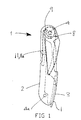
- the secateurs 1 comprise a fixed handle 2 which acts as a housing for the various parts in a similar manner to the housing for a pen knife.
- the fixed handle 2 contains a movable handle 3 which projects from the fixed handle 2 so that it may be easily gripped for opening of the secateurs.
- the movable handle is pivotally connected to the fixed handle 2 by a pivot pin 4.
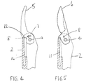
- a pair of blades, namely a concave blade 5 and a convex blade 6 are also housed within the fixed handle 2 and are pivotally connected at the pivot pin 4. As shown in detail in Figs.
- the concave blade 5 includes a slot 7 for engagement with a projection 8 on the convex blade 6.
- the moveable handle 3 includes an arc shape cut out 9 within which runs the projection 8 on the convex blade 6.
- Leaf spring 11, 11a are mounted on the fixed handle 2 and act on the blades 5 and 6.
- the movable handle 3 includes a projecting gripping means 13 to enable the user to grip the movable handle and rotate it out of the fixed handle 2.
- the secateurs 1 may be carried about and folded up as shown in fig. 1.
- the movable handle 3 is gripped by the gripping means 13 and is rotated out of the fixed handle 2 as shown in fig. 2, in the direction of arrow A.
- the concave blade 5 is pulled out automatically by engagement of the projecting pin 8 with the cut-out 9 of the moveable handle 3.
- This causes the convex blade 6 to be pulled out of the fixed handle housing 2 by engagement of the pin 8 with the slot 7.
- the concave blade 5 reaches its extreme position where further rotation is prevented by the action of the leaf spring 11a.
- a cam surface 12 of the lower part of concave blade 5 co-operates with a corresponding surface of the leaf spring 11a to urge the concave blade 5 into the fixed operating position and the leaf spring 11a also fixedly retains the concave blade 5 in this fixed position by this urging action.
- the convex blade 6 has reached its cutting position at this stage. It will be noted that the movable handle 3 has rotated approximately 300 degrees at this stage. On still further rotation of the movable handle 3 to the position of approximately 330 degrees as shown in fig. 6, in the direction of arrow B, the convex blade 6 is urged towards the concave blade 5 in a cutting action against pressure of the leaf spring 11. The cutting arc of the convex blade 6 is stopped by the pin 8 engaging in the slot 7. During this cutting action, the concave blade 5 remains in the locked position and on release of pressure on the movable handle 3, the handle moves back to its 300 degree position for cutting action.
- the movable handle 3 When cutting is completed the movable handle 3 may be rotated back into its non-operating position and this in turn causes the blades to retract into the fixed handle 2.
- the lateral extension 13 of the movable handle 3 engages the blades 5, 6 causing them to retract with it into the fixed handle 2.
- the leaf springs 11, 11a engage against the blades 5, 6 urging them in the non-operating position inside the fixed handle 2.
- the fixed handle 2 comprises two separate parts 2a and 2b which are sandwiched together by means of the rivets or bolts 4, 4a with the moving parts between them to form the secados 1.
- the arrangement comprises a spring washer 19 against which the moving handle 3 is arranged, against which the fixed concave blade 5 is arranged against which the movable convex blade 5 is arranged which is itself arranged against the other side of the fixed handle 2b.
- the fixed handle 2 may also comprise a hollow space for the inclusion of additional tools for example a knife or any other useful implement.
- the end cross sections of the leaf springs 11, 11a can be seen acting against the blades 5, 6.
- the leaf springs 11, 11a are supported to the fixed handle part to approximately one third of the way along the fixed handle starting from the remote end such that the free ends of the leaf springs are free to move and act against the blades 5, 6 in the urging manner described above.
- the pin 4 comprises a bolt 18 which is connected by means of a thread to a nut 15.
- a bearing bush 16 is provided between the bolt and the moving parts 3, 5, and 6.
- the pin 4 is comprised of a rivet 17 in place of the bolt 18 and nut 15 of figure 7.
- the lateral extension 13 which acts both as an operating handle to enable the moveable handle to be levered out from the fixed handle and also as an engaging member for the blades 5 and 6 during the return of the blades and moveable handle to the non-operating position back in the fixed handle 2.
- the moveable handle also comprises the arc shaped cut out 9 which determines the extent of rotation of the moveable handle 3 before it engages the blades 5, 6.
- the blades 5, 6 are engaged by the moveable handle when the ends 9a of the arc 9 act against the pin 8 of the concave blade 6.
- the angle of the arc will be such that sufficient angle of rotation is left after engagement of the blades to rotate them the required 180 degrees to the operating position. At this position the movable handle will then need to be at the most desirable angle to act as a handle to operate the opening and closing of the blades in the cutting action.
- This angle is preferably 50 degrees but could be anywhere between 20 and 80 degrees.
- the angle of the arc-shaped slot 9 corresponding to the angle of pivot of the moveable handle before engagement of the blades is preferably 130 degrees but could be within the range 100 to 160 degrees.
- the invention provides a pair of secateurs which is easy to carry in ones pocket and which is a simple and effective mechanism which is also relatively sturdy and may allow cutting of significantly large branches.
- the invention is not limited to the embodiments illustrated.
- any other types of hand tools and cutting implements may be designed based on the principle of the invention.
- the person skilled in the art will realise that a pair of household/garden shears, a pair of nail clippers or alternatively a pair of pliers could be constructed in accordance with the mechanism of the invention. It will be appreciated that there is a wide range of applications for the invention.
Landscapes
- Life Sciences & Earth Sciences (AREA)
- Forests & Forestry (AREA)
- Engineering & Computer Science (AREA)
- Mechanical Engineering (AREA)
- Scissors And Nippers (AREA)
- Knives (AREA)
Applications Claiming Priority (2)
| Application Number | Priority Date | Filing Date | Title |
|---|---|---|---|
| GB9424070 | 1994-11-29 | ||
| GB9424070A GB9424070D0 (en) | 1994-11-29 | 1994-11-29 | A cutting implement |
Publications (1)
| Publication Number | Publication Date |
|---|---|
| EP0714736A1 true EP0714736A1 (de) | 1996-06-05 |
Family
ID=10765152
Family Applications (1)
| Application Number | Title | Priority Date | Filing Date |
|---|---|---|---|
| EP95308447A Ceased EP0714736A1 (de) | 1994-11-29 | 1995-11-24 | Zusammenklappbares Werkzeug |
Country Status (3)
| Country | Link |
|---|---|
| EP (1) | EP0714736A1 (de) |
| JP (1) | JPH08257258A (de) |
| GB (2) | GB9424070D0 (de) |
Cited By (20)
| Publication number | Priority date | Publication date | Assignee | Title |
|---|---|---|---|---|
| EP0854014A1 (de) * | 1997-01-15 | 1998-07-22 | Fiskars Inc. | Federbelastetes Werkzeug zum Verwendung in Mehrzweckwerkzeugen |
| US6282997B1 (en) | 1993-11-29 | 2001-09-04 | Sog Specialty Knives, Inc. | Multipurpose tool and components thereof |
| US6389625B1 (en) | 2000-01-12 | 2002-05-21 | Leatherman Tool Group, Inc. | Multipurpose tool including folding scissors |
| EP1327505A1 (de) * | 2002-01-09 | 2003-07-16 | Wenger S.A. | Klappbares Mehrzweckwerkzeug |
| US6763543B2 (en) | 2000-01-12 | 2004-07-20 | Leatherman Tool Group, Inc. | Multipurpose tool including folding scissors |
| USD528396S1 (en) | 2005-06-14 | 2006-09-19 | Leatherman Tool Group, Inc. | Blade opener for a folding knife |
| USD529789S1 (en) | 2005-06-14 | 2006-10-10 | Leatherman Tool Group, Inc. | Carabiner with pivoted gate |
| USD530180S1 (en) | 2005-06-14 | 2006-10-17 | Leatherman Tool Group, Inc. | Handle for a folding knife |
| USD533043S1 (en) | 2005-06-14 | 2006-12-05 | Leatherman Tool Group, Inc. | Pair of handle sides for a folding knife |
| USD538138S1 (en) | 2005-06-14 | 2007-03-13 | Leatherman Tool Group, Inc. | Folding carabiner with spring gate |
| USD541618S1 (en) | 2005-12-14 | 2007-05-01 | Leatherman Tool Group, Inc. | Pair of handles for a folding multipurpose tool including shears |
| US7337486B2 (en) | 2006-04-25 | 2008-03-04 | Leatherman Tool Group, Inc. | Hand tool |
| USD564326S1 (en) | 2006-04-25 | 2008-03-18 | Leatherman Tool Group, Inc. | Folding multipurpose hand tool |
| US7353736B2 (en) | 2005-07-27 | 2008-04-08 | Leatherman Tool Group, Inc. | Enhanced multi-function hand tool |
| USD567601S1 (en) | 2007-03-09 | 2008-04-29 | Leatherman Tool Group, Inc. | Multipurpose tool including bypass pruner |
| USD573435S1 (en) | 2006-04-25 | 2008-07-22 | Leatherman Tool Group, Inc. | Folding multipurpose hand tool |
| USD576010S1 (en) | 2007-03-09 | 2008-09-02 | Leatherman Tool Group, Inc. | Rotatable tool handle |
| US7596870B2 (en) | 2004-03-02 | 2009-10-06 | Leatherman Tool Group, Inc. | Folding multipurpose tool with shears and comfortable handles |
| US7676931B2 (en) | 2005-06-14 | 2010-03-16 | Leatherman Tool Group, Inc. | Folding knife |
| US8161653B2 (en) | 2007-11-12 | 2012-04-24 | Leatherman Tool Group, Inc. | Folding tool having a rotatable locking mechanism |
Families Citing this family (1)
| Publication number | Priority date | Publication date | Assignee | Title |
|---|---|---|---|---|
| US6065213A (en) * | 1998-11-06 | 2000-05-23 | Leatherman Tool Group, Inc. | Folding scissors |
Citations (5)
| Publication number | Priority date | Publication date | Assignee | Title |
|---|---|---|---|---|
| DE23695C (de) * | böntgen & SABIN in Solingen | Zusammenlegbare Taschenscheere | ||
| GB212315A (en) | 1922-12-08 | 1924-03-10 | Mary Sargant Florence | Improvements relating to indicators applicable to the teaching of music or the selection and combining of colours |
| FR581903A (fr) * | 1924-05-22 | 1924-12-08 | Ciseaux pliants de poche pouvant être utilisés comme canif | |
| FR654286A (fr) * | 1928-05-14 | 1929-04-04 | Nécessaire pouvant être utilisé comme organe de manoeuvre pour les outils qui y sont renfermés | |
| FR2518005A1 (fr) * | 1981-12-10 | 1983-06-17 | Aoki Takaaki | Outil a main du type ciseaux repliables, avec un boitier incorpore |
Family Cites Families (1)
| Publication number | Priority date | Publication date | Assignee | Title |
|---|---|---|---|---|
| FR2589382B1 (fr) * | 1985-11-04 | 1989-07-21 | Nordet Flavien | Dispositif constitue d'une ou deux poignees amovibles permettant l'utilisation des doubles machoires d'un outil a main a deux branches |
-
1994
- 1994-11-29 GB GB9424070A patent/GB9424070D0/en active Pending
-
1995
- 1995-09-26 GB GB9519809A patent/GB2295570B/en not_active Expired - Fee Related
- 1995-11-24 EP EP95308447A patent/EP0714736A1/de not_active Ceased
- 1995-11-29 JP JP31095795A patent/JPH08257258A/ja active Pending
Patent Citations (5)
| Publication number | Priority date | Publication date | Assignee | Title |
|---|---|---|---|---|
| DE23695C (de) * | böntgen & SABIN in Solingen | Zusammenlegbare Taschenscheere | ||
| GB212315A (en) | 1922-12-08 | 1924-03-10 | Mary Sargant Florence | Improvements relating to indicators applicable to the teaching of music or the selection and combining of colours |
| FR581903A (fr) * | 1924-05-22 | 1924-12-08 | Ciseaux pliants de poche pouvant être utilisés comme canif | |
| FR654286A (fr) * | 1928-05-14 | 1929-04-04 | Nécessaire pouvant être utilisé comme organe de manoeuvre pour les outils qui y sont renfermés | |
| FR2518005A1 (fr) * | 1981-12-10 | 1983-06-17 | Aoki Takaaki | Outil a main du type ciseaux repliables, avec un boitier incorpore |
Cited By (27)
| Publication number | Priority date | Publication date | Assignee | Title |
|---|---|---|---|---|
| US6282997B1 (en) | 1993-11-29 | 2001-09-04 | Sog Specialty Knives, Inc. | Multipurpose tool and components thereof |
| US6474202B2 (en) | 1993-11-29 | 2002-11-05 | Sog Specialty Knives, Inc. | Multipurpose tool and components thereof |
| EP0854014A1 (de) * | 1997-01-15 | 1998-07-22 | Fiskars Inc. | Federbelastetes Werkzeug zum Verwendung in Mehrzweckwerkzeugen |
| US5946752A (en) * | 1997-01-15 | 1999-09-07 | Fiskars Inc. | Spring biased implement for use in multi-function tools |
| US6389625B1 (en) | 2000-01-12 | 2002-05-21 | Leatherman Tool Group, Inc. | Multipurpose tool including folding scissors |
| US6510767B1 (en) | 2000-01-12 | 2003-01-28 | Leatherman Tool Goup, Inc. | Folding multipurpose tool including blade lock release mechanism |
| US6763543B2 (en) | 2000-01-12 | 2004-07-20 | Leatherman Tool Group, Inc. | Multipurpose tool including folding scissors |
| US6990702B2 (en) | 2000-01-12 | 2006-01-31 | Leatherman Tool Group, Inc. | Multipurpose tool including folding scissors |
| US7051627B2 (en) | 2000-01-12 | 2006-05-30 | Leatherman Tool Group, Inc. | Folding multipurpose tool including blade lock release mechanism |
| EP1327505A1 (de) * | 2002-01-09 | 2003-07-16 | Wenger S.A. | Klappbares Mehrzweckwerkzeug |
| US7607231B2 (en) | 2004-03-02 | 2009-10-27 | Leatherman Tool Group, Inc. | Folding multipurpose tool with shears and comfortable handles |
| US7596870B2 (en) | 2004-03-02 | 2009-10-06 | Leatherman Tool Group, Inc. | Folding multipurpose tool with shears and comfortable handles |
| USD530180S1 (en) | 2005-06-14 | 2006-10-17 | Leatherman Tool Group, Inc. | Handle for a folding knife |
| USD529789S1 (en) | 2005-06-14 | 2006-10-10 | Leatherman Tool Group, Inc. | Carabiner with pivoted gate |
| USD538138S1 (en) | 2005-06-14 | 2007-03-13 | Leatherman Tool Group, Inc. | Folding carabiner with spring gate |
| USD533043S1 (en) | 2005-06-14 | 2006-12-05 | Leatherman Tool Group, Inc. | Pair of handle sides for a folding knife |
| US7676931B2 (en) | 2005-06-14 | 2010-03-16 | Leatherman Tool Group, Inc. | Folding knife |
| USD528396S1 (en) | 2005-06-14 | 2006-09-19 | Leatherman Tool Group, Inc. | Blade opener for a folding knife |
| US7921752B2 (en) | 2005-07-27 | 2011-04-12 | Leatherman Tool Group, Inc. | Enhanced multi-function hand tool |
| US7353736B2 (en) | 2005-07-27 | 2008-04-08 | Leatherman Tool Group, Inc. | Enhanced multi-function hand tool |
| USD541618S1 (en) | 2005-12-14 | 2007-05-01 | Leatherman Tool Group, Inc. | Pair of handles for a folding multipurpose tool including shears |
| US7337486B2 (en) | 2006-04-25 | 2008-03-04 | Leatherman Tool Group, Inc. | Hand tool |
| USD573435S1 (en) | 2006-04-25 | 2008-07-22 | Leatherman Tool Group, Inc. | Folding multipurpose hand tool |
| USD564326S1 (en) | 2006-04-25 | 2008-03-18 | Leatherman Tool Group, Inc. | Folding multipurpose hand tool |
| USD576010S1 (en) | 2007-03-09 | 2008-09-02 | Leatherman Tool Group, Inc. | Rotatable tool handle |
| USD567601S1 (en) | 2007-03-09 | 2008-04-29 | Leatherman Tool Group, Inc. | Multipurpose tool including bypass pruner |
| US8161653B2 (en) | 2007-11-12 | 2012-04-24 | Leatherman Tool Group, Inc. | Folding tool having a rotatable locking mechanism |
Also Published As
| Publication number | Publication date |
|---|---|
| GB2295570A (en) | 1996-06-05 |
| GB9519809D0 (en) | 1995-11-29 |
| JPH08257258A (ja) | 1996-10-08 |
| GB2295570B (en) | 1998-06-03 |
| GB9424070D0 (en) | 1995-01-18 |
Similar Documents
| Publication | Publication Date | Title |
|---|---|---|
| GB2295570A (en) | A cutting implement with pivoted blades | |
| US5787589A (en) | Cutting shears particularly secateurs | |
| US6513248B2 (en) | Power lever cutting device | |
| JP4995381B2 (ja) | 切断具、特に植木ばさみ | |
| US6430768B2 (en) | Folding multi-tool with adjustable pliers | |
| AU703581B2 (en) | Lopper | |
| US5212844A (en) | Pocket tool with retractable jaws | |
| US5058277A (en) | Compound action cutting tool | |
| US5724688A (en) | Multipurpose tool | |
| CA1152731A (en) | Hand tool for cutting plastic pipe or the like | |
| US4502220A (en) | Hand-held type opening and closing action tool | |
| WO2000009298A9 (en) | Remote gripping or cutting apparatus having a rotatable head | |
| EP1735129A1 (de) | Klappbares mehrzweckwerkzeug mit schere und bequemen griffen | |
| WO1997025187A1 (en) | Pruning implement | |
| CN107846847B (zh) | 兼备树枝悬挂及缓解冲击功能的剪枝剪 | |
| CN100546463C (zh) | 修枝剪或相应刀具 | |
| EP1737625A2 (de) | Schneidwirkungs-werkzeug mit verstellbarem öffnungswinkel | |
| US20220331999A1 (en) | Multipurpose tool | |
| KR0138313Y1 (ko) | 전지가위 | |
| WO2015067319A1 (en) | Lopper with angular adjustment | |
| US20040020059A1 (en) | Shears | |
| GB2447303A (en) | Gardening shears having energy saving function | |
| EP4702833A1 (de) | Federklammer | |
| CN221532204U (zh) | 一种剪刀 | |
| EP0826299B1 (de) | Heckenschere |
Legal Events
| Date | Code | Title | Description |
|---|---|---|---|
| PUAI | Public reference made under article 153(3) epc to a published international application that has entered the european phase |
Free format text: ORIGINAL CODE: 0009012 |
|
| AK | Designated contracting states |
Kind code of ref document: A1 Designated state(s): DE DK ES FR GB IT |
|
| 17P | Request for examination filed |
Effective date: 19960729 |
|
| 17Q | First examination report despatched |
Effective date: 19980703 |
|
| GRAG | Despatch of communication of intention to grant |
Free format text: ORIGINAL CODE: EPIDOS AGRA |
|
| STAA | Information on the status of an ep patent application or granted ep patent |
Free format text: STATUS: THE APPLICATION HAS BEEN REFUSED |
|
| 18R | Application refused |
Effective date: 19991129 |