EP0714070B1 - Bar code label - Google Patents
Bar code label Download PDFInfo
- Publication number
- EP0714070B1 EP0714070B1 EP96100836A EP96100836A EP0714070B1 EP 0714070 B1 EP0714070 B1 EP 0714070B1 EP 96100836 A EP96100836 A EP 96100836A EP 96100836 A EP96100836 A EP 96100836A EP 0714070 B1 EP0714070 B1 EP 0714070B1
- Authority
- EP
- European Patent Office
- Prior art keywords
- bar code
- recesses
- code label
- engraved
- base
- Prior art date
- Legal status (The legal status is an assumption and is not a legal conclusion. Google has not performed a legal analysis and makes no representation as to the accuracy of the status listed.)
- Expired - Lifetime
Links
Images
Classifications
-
- G—PHYSICS
- G06—COMPUTING OR CALCULATING; COUNTING
- G06K—GRAPHICAL DATA READING; PRESENTATION OF DATA; RECORD CARRIERS; HANDLING RECORD CARRIERS
- G06K1/00—Methods or arrangements for marking the record carrier in digital fashion
- G06K1/12—Methods or arrangements for marking the record carrier in digital fashion otherwise than by punching
- G06K1/125—Methods or arrangements for marking the record carrier in digital fashion otherwise than by punching by magnetic means
-
- G—PHYSICS
- G06—COMPUTING OR CALCULATING; COUNTING
- G06K—GRAPHICAL DATA READING; PRESENTATION OF DATA; RECORD CARRIERS; HANDLING RECORD CARRIERS
- G06K19/00—Record carriers for use with machines and with at least a part designed to carry digital markings
- G06K19/02—Record carriers for use with machines and with at least a part designed to carry digital markings characterised by the selection of materials, e.g. to avoid wear during transport through the machine
-
- G—PHYSICS
- G06—COMPUTING OR CALCULATING; COUNTING
- G06K—GRAPHICAL DATA READING; PRESENTATION OF DATA; RECORD CARRIERS; HANDLING RECORD CARRIERS
- G06K19/00—Record carriers for use with machines and with at least a part designed to carry digital markings
- G06K19/06—Record carriers for use with machines and with at least a part designed to carry digital markings characterised by the kind of the digital marking, e.g. shape, nature, code
- G06K19/06187—Record carriers for use with machines and with at least a part designed to carry digital markings characterised by the kind of the digital marking, e.g. shape, nature, code with magnetically detectable marking
-
- G—PHYSICS
- G06—COMPUTING OR CALCULATING; COUNTING
- G06K—GRAPHICAL DATA READING; PRESENTATION OF DATA; RECORD CARRIERS; HANDLING RECORD CARRIERS
- G06K19/00—Record carriers for use with machines and with at least a part designed to carry digital markings
- G06K19/06—Record carriers for use with machines and with at least a part designed to carry digital markings characterised by the kind of the digital marking, e.g. shape, nature, code
- G06K19/06187—Record carriers for use with machines and with at least a part designed to carry digital markings characterised by the kind of the digital marking, e.g. shape, nature, code with magnetically detectable marking
- G06K19/06196—Constructional details
-
- G—PHYSICS
- G06—COMPUTING OR CALCULATING; COUNTING
- G06K—GRAPHICAL DATA READING; PRESENTATION OF DATA; RECORD CARRIERS; HANDLING RECORD CARRIERS
- G06K19/00—Record carriers for use with machines and with at least a part designed to carry digital markings
- G06K19/06—Record carriers for use with machines and with at least a part designed to carry digital markings characterised by the kind of the digital marking, e.g. shape, nature, code
- G06K19/08—Record carriers for use with machines and with at least a part designed to carry digital markings characterised by the kind of the digital marking, e.g. shape, nature, code using markings of different kinds or more than one marking of the same kind in the same record carrier, e.g. one marking being sensed by optical and the other by magnetic means
- G06K19/10—Record carriers for use with machines and with at least a part designed to carry digital markings characterised by the kind of the digital marking, e.g. shape, nature, code using markings of different kinds or more than one marking of the same kind in the same record carrier, e.g. one marking being sensed by optical and the other by magnetic means at least one kind of marking being used for authentication, e.g. of credit or identity cards
- G06K19/14—Record carriers for use with machines and with at least a part designed to carry digital markings characterised by the kind of the digital marking, e.g. shape, nature, code using markings of different kinds or more than one marking of the same kind in the same record carrier, e.g. one marking being sensed by optical and the other by magnetic means at least one kind of marking being used for authentication, e.g. of credit or identity cards the marking being sensed by radiation
-
- G—PHYSICS
- G06—COMPUTING OR CALCULATING; COUNTING
- G06K—GRAPHICAL DATA READING; PRESENTATION OF DATA; RECORD CARRIERS; HANDLING RECORD CARRIERS
- G06K7/00—Methods or arrangements for sensing record carriers, e.g. for reading patterns
- G06K7/08—Methods or arrangements for sensing record carriers, e.g. for reading patterns by means detecting the change of an electrostatic or magnetic field, e.g. by detecting change of capacitance between electrodes
- G06K7/082—Methods or arrangements for sensing record carriers, e.g. for reading patterns by means detecting the change of an electrostatic or magnetic field, e.g. by detecting change of capacitance between electrodes using inductive or magnetic sensors
- G06K7/087—Methods or arrangements for sensing record carriers, e.g. for reading patterns by means detecting the change of an electrostatic or magnetic field, e.g. by detecting change of capacitance between electrodes using inductive or magnetic sensors flux-sensitive, e.g. magnetic, detectors
-
- G—PHYSICS
- G06—COMPUTING OR CALCULATING; COUNTING
- G06K—GRAPHICAL DATA READING; PRESENTATION OF DATA; RECORD CARRIERS; HANDLING RECORD CARRIERS
- G06K19/00—Record carriers for use with machines and with at least a part designed to carry digital markings
- G06K19/06—Record carriers for use with machines and with at least a part designed to carry digital markings characterised by the kind of the digital marking, e.g. shape, nature, code
- G06K2019/06215—Aspects not covered by other subgroups
- G06K2019/06271—Relief-type marking
Definitions
- the present invention relates to a bar code label in which information on each of various commodities, outdoor installations or individuals are recorded as engraved in the form of characters and bar codes.
- the bar code label is well known and widely used as attached on the surface of a box or package in which a commodity or delivery is packed.
- the bar code label carries a variety of information, as coded in the form of bars different in width from one another, on such commodity. The information are used for a higher efficiency and less labor in sales calculation, inventory control or assortment.
- bar code is black bars printed on the white surface of a bar code label.
- the label surface is stained with an oil or dirt or if the blackness of the coded bars fades, the information recorded in the bar code label cannot possibly be read positively and accurately. Particularly, there is a problem in reading the bar code label outdoors.
- a magnetic bar code reading system which can be used in any environment.
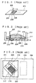
- engraved recesses (characters and bar codes) 202, 202 ' , 203 , ⁇ ⁇ ⁇ are made, as shown in Fig. 1, on a bar code label 201 made of a metal such as iron and the recesses are magnetically detected by means of a ferromagnetic magnetic resistance device (will be referred to as "MR device” hereinafter) and a permanent magnet.
- MR device ferromagnetic magnetic resistance device
- the head at the bottom of a main body 204 in which the MR device and permanent magnet are integrally incorporated is swept on the engraved bar code label 201 to read the recess pattern consisting of the recesses 202, 202 ' , 203 , ⁇ ⁇ ⁇ .
- the principle of this bar code reading will be discussed below:
- the engraved recesses 202, 202' , 203 , ⁇ ⁇ ⁇ are magnetized by the DC magnetic formed by the permanent magnet.
- the magnetic field formed by these magnetized recesses causes the magnetic flux distribution over the recesses to change and this change of the magnetic flux distribution results in a resistance change of the MR device.
- the resistance change is passed to the signal processing circuit provided in the head of the main body 204 in which they are converted into a binary-coded signal (0 or 1) correspondingly to the code represented by the recess pattern. This binary-coded signal is supplied to the decoder for recognition of the bar code pattern.
- the conventional head of the magnetic bar code reader operating on the above-mentioned principle has a tip of which the structure will be discussed below with reference to Fig. 2. Namely, for an electrical connection between an input wire of an MR device 206 made on a printed circuit board 205 through a well-known IC manufacturing process and an external lead wire 207 through which a current is supplied to detect a magnetic field change as a voltage, the circuit board 205 is connected to an electrode 209 by means of a bonding wire 208 and the external lead wire 207 is spot-joined to the electrode 209 by means of a solder joint 210.
- the electrode 209 and circuit board 205 are attached to an internal substrate 211. Further, the internal substrate 211 and electrode 209 are attached to a head frame 212 and sealed from below with a coating film 213.
- a permanent magnet 214 provided for exciting is attached to the internal substrate 211 and sealed with a coating film 215.
- a generally square MR device is used as shown in Fig. 3.
- a magnetic resistance film 217 formed on a circuit board 216 made of, for example, a glass is provided in such a structure that it is folded back in parallel to the lateral side of the circuit board 216.
- a plurality of such magnetic resistance films is provided as cascade-connected.
- the number of the magnetic resistance films thus provided is such that the whole resistance will be on the order several kiloohms.
- a current-supplying electrode 218 is provided on either end of the magnetic resistance film 217 in such a manner that an ohmic contact can be assured.
- these patterns are so set as to form together a generally square shape in many cases.
- the above-mentioned MR device is inclined more than 30 deg. with respect to bar code recesses 219 and a permanent magnet 220 which applies a biasing magnetic field is provided on the MR device to make a head 221 which will be swept on recesses 223, engraved in the form of bar code in an iron sheet 222, in a direction perpendicular to the length of the engraved recesses 223, thereby reading the bar code.
- a bar code label made of any other metal sheet than the iron sheet is so resistant against contamination or staining that even when the label surface is stained with a dirt or the like, it can be washed with water to remove such dirt.
- the label in case the label is made of an iron sheet, it will be rusty and thus corroded.
- any iron-sheet bar code label is not suitably usable in a place where the atmosphere is very salty.
- the bonding wire 208 is provided as bonded to the electrode 205 on the substrate (semiconductor substrate) of the MR device 206 by using an ultrasonic bonder or the like, a air gap d (about 0.3 mm) must be provided under these elements.
- This air gap causes the strength of the magnetic lines of force produced by the engraved recesses, that is to be detected by the MR device, to he extremely small.
- the MR device has only a low sensitivity to the magnetic lines of force formed by the bar code recesses.
- the sensitivity of the MR device is found very low. For example, when about 0.1 mm is off the label surface in relation to a pattern of minimum recesses of 0.5 mm, the head can hardly read the code represented by the recess pattern.
- a common MR device of 0.5 to 0.6 mm in length and width should preferably be inclined 45 deg. with respect to the length of the recesses to apply a biasing magnetic field longitudinally of the recesses in order to read the bar code with a high sensitivity.
- the width of the MR device will be about 0.7 mm to 0.85 mm and thus it is apparent that the MR device cannot read any engraved recess of 0.5 mm in minimum width. Also even if a bar code reading head is constructed with the MR device not inclined 45 deg. (the biasing magnetic field may be applied from a direction inclined 45 deg.) but directed longitudinally of the engraved recesses at the sacrifice of the sensitivity to some extent, any common magnetic sensor element having a large width, if fitted, in the head cannot read a high resolution (namely, narrow) bar code recess pattern.
- JP-1 280 593 on which the preamble of claim 1 is based, discloses a bar code label having information recorded therein, the bar code label comprising: a base; and a recording area provided on the top surface of the base, the recording area being provided with recesses engraved each in a predetermined shape corresponding to information to be recorded.
- JP-1 233 675 discloses a bar code label similar to that described in JP-1 280 593.
- a first aspect of the present invention provides a bar code label having information recorded therein, the bar code label comprising: a base of a magnetic material; and a recording area provided on the upper surface of the base, the recording area being provided with recesses engraved each in a predetermined shape corresponding to information to be recorded; wherein the upper surface of the base is coated with a non-magnetic material; characterised in that narrower recesses are engraved deeper than wider recesses.
- a second aspect of the present invention provides a bar code label having information recorded therein, the bar code label comprising: a base of a magnetic material; and a recording area provided on the upper surface of the base, the recording area being provided with recesses engraved each in a predetermined shape corresponding to information to be recorded; and wherein the base of the bar code label is coated with a stainless material; characterised in that narrower recesses are engraved deeper than wider recesses.
- the stainless material is a plastics material, lead, tin or nickel.
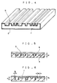
- Fig. 4 shows a bar code label, this engraved bar code label comprising a base 1 having formed a protective film 2 on the outer surface thereof.
- the base 1 is a square sheet made of a material such as iron or the like, the sheet having the top and bottom surfaces thereof machined like a mirror surface to minimize the surface irregularity.
- the base 1 has formed as engraved on the top surface thereof a record area 3 carrying, for identification, a variety of information on, for example, the name of a unit or force to which a solder belongs or the proprietor, serial number or the line of an outdoor installation such as construction machine, vehicle, gas cylinder, machine part, steel tower or the like.
- the record area 3 consists of recesses different in width from each other correspondingly to various information. In this first embodiment, the recesses are formed by etching or punching.
- the protective film 2 is provided to protect the record area 3 for a long term being eroded, and it is selected from among plastic, nickel, lead(Pb) or tin (Sn).
- the stainless material such as plastic, nickel or the like is applied as a thin film on the entire surface of the base 1.
- the lead or tin is applied as plated on the entire surface of the base 1.
- the protective film 2 is applied on the entire surface of the base 1. Namely, it can be easily manufactured with less manufacuturing costs.
- Fig. 5 shows another bar code label.
- This engraved bar code label comprises a film-shaped base 4 made of a ferromagnetic material such as iron (Fe), cobalt(Co), nickel(Ni) or the like and on which a record area 5 is provided which concists of recesses different in width from each other and which are engraved with a predetermined spacing from one to another recess, and a nonmagnetic film 6 so molded in the record area 5 or the base 4 as to completely bury the recesses.
- a film-shaped base 4 made of a ferromagnetic material such as iron (Fe), cobalt(Co), nickel(Ni) or the like and on which a record area 5 is provided which concists of recesses different in width from each other and which are engraved with a predetermined spacing from one to another recess, and a nonmagnetic film 6 so molded in the record area 5 or the base 4 as to completely bury the recesses.
- the base 4 has the top and bottom surfaces thereof machined with a high precision like a mirror face to prevent any read error form taking place.
- the record area 5 has engraved in the top surface of the base 4 recesses each having a predetermined width corresponding to an information to be recorded, spaced a predetermined distance between adjoining one and engraved to a predetermined depth d .
- this record area 5 is applied with a magnetic field from outside by the magnet or the like, the magnetic lines of force are concentrated laterally of the recesses, resulting in a distortion of the distribution of the magnetic lines of force.
- the nonmagnetic film 6 is a mold of a nonmagnetic material such as plastic or the like to a predetermined thickness to the record area 5.
- Fig. 6 shows the engraved bar code label, in which the depth d 1 of a recess 7 of smaller width W 1 is larger than the depth d 2 of a one 7 of larger width W 2 , namely, d 1 > d 2 .
- the depth d 2 is smaller than the depth d 1 , it is possible to prevent the magnetic field near the wide recess from being destorted largely, which leads to less distortion of the magnetic field on the adjoining narrow recess.
- the recess width is changed correspondingly to the recess width; thus, the output waveform corresponding to the recess 7 is less distorted during the information reading and thus a high information density, namely. high resolution bar code label can be read accurately.
- the bar code label according to the present invention has recesses engraved in a record area on the bar code label. Even with any staining, sunlight or the like, the record area cannot be lost. Therefore, information can be positively recorded on the bar code label, praticularly in outdoor use for a long term.
- the magnetic engraved bar code label permits to record an information on the magnetic material with a width and spacing corresponding to the information based on the fact that when the record area made of a magnetic material is applied with an external magnetic field from a ferromagnetic material such as a magnet or the like, the distribution of magnetic lines of line produced by the respective recesses in the record area is changed at the recess edges.
- the engraved bar code labels according to the present invention are made of a magnetic material (metal) coated with a resin or the like. So even if stained or somewhat impaired, the label can still be used. Namely, it can be suitably used in an environment such as outdoor, factory or the like where the label is likely to be stained.
Landscapes
- Engineering & Computer Science (AREA)
- Physics & Mathematics (AREA)
- General Physics & Mathematics (AREA)
- Theoretical Computer Science (AREA)
- Artificial Intelligence (AREA)
- Computer Vision & Pattern Recognition (AREA)
- Measuring Magnetic Variables (AREA)
- Magnetic Record Carriers (AREA)
- Magnetic Heads (AREA)
- Transmission And Conversion Of Sensor Element Output (AREA)
Description
characterised in that narrower recesses are engraved deeper than wider recesses.
characterised in that narrower recesses are engraved deeper than wider recesses.
Claims (3)
- A bar code label having information recorded therein, the bar code label comprising: a base (1) of a magnetic material; and a recording area (3) provided on the upper surface of the base, the recording area (3) being provided with recesses engraved each in a predetermined shape corresponding to information to be recorded; wherein the upper surface of the base (1) is coated with a non-magnetic material;
characterised in that narrower recesses (7) are engraved deeper than wider recesses. - A bar code label having information recorded therein, the bar code label comprising: a base (1) of a magnetic material; and a recording area (3) provided on the upper surface of the base, the recording area (3) being provided with recesses engraved each in a predetermined shape corresponding to information to be recorded; and wherein the base of the bar code label is coated with a stainless material (2);
characterised in that narrower recesses (7) are engraved deeper than wider recesses. - A bar code label as claimed in claim 2 wherein the stainless material is a plastics material, lead, tin or nickel.
Applications Claiming Priority (11)
| Application Number | Priority Date | Filing Date | Title |
|---|---|---|---|
| JP2021795A JPH03226886A (en) | 1990-01-31 | 1990-01-31 | Magnetic bar code detector |
| JP21795/90 | 1990-01-31 | ||
| JP71142/90 | 1990-03-20 | ||
| JP71141/90 | 1990-03-20 | ||
| JP71140/90 | 1990-03-20 | ||
| JP2071140A JPH0786895B2 (en) | 1990-03-20 | 1990-03-20 | Record form reader |
| JP2071142A JPH0679200B2 (en) | 1990-03-20 | 1990-03-20 | Stamp record sheet |
| JP2071141A JPH03269383A (en) | 1990-03-20 | 1990-03-20 | Magnetic sensor and its signal processing system |
| JP287798/90 | 1990-10-25 | ||
| JP2287798A JPH04160691A (en) | 1990-10-25 | 1990-10-25 | Magnetic resistance element and magnetic bar code detector |
| EP91101047A EP0440124B1 (en) | 1990-01-31 | 1991-01-28 | Bar code label and bar code reader |
Related Parent Applications (2)
| Application Number | Title | Priority Date | Filing Date |
|---|---|---|---|
| EP91101047.8 Division | 1991-01-28 | ||
| EP91101047A Division EP0440124B1 (en) | 1990-01-31 | 1991-01-28 | Bar code label and bar code reader |
Publications (3)
| Publication Number | Publication Date |
|---|---|
| EP0714070A2 EP0714070A2 (en) | 1996-05-29 |
| EP0714070A3 EP0714070A3 (en) | 1996-06-05 |
| EP0714070B1 true EP0714070B1 (en) | 1998-07-08 |
Family
ID=27520373
Family Applications (4)
| Application Number | Title | Priority Date | Filing Date |
|---|---|---|---|
| EP96100838A Withdrawn EP0714072A2 (en) | 1990-01-31 | 1991-01-28 | Bar code label and bar code reader |
| EP96100836A Expired - Lifetime EP0714070B1 (en) | 1990-01-31 | 1991-01-28 | Bar code label |
| EP91101047A Expired - Lifetime EP0440124B1 (en) | 1990-01-31 | 1991-01-28 | Bar code label and bar code reader |
| EP96100837A Expired - Lifetime EP0714071B1 (en) | 1990-01-31 | 1991-01-28 | Bar code reader |
Family Applications Before (1)
| Application Number | Title | Priority Date | Filing Date |
|---|---|---|---|
| EP96100838A Withdrawn EP0714072A2 (en) | 1990-01-31 | 1991-01-28 | Bar code label and bar code reader |
Family Applications After (2)
| Application Number | Title | Priority Date | Filing Date |
|---|---|---|---|
| EP91101047A Expired - Lifetime EP0440124B1 (en) | 1990-01-31 | 1991-01-28 | Bar code label and bar code reader |
| EP96100837A Expired - Lifetime EP0714071B1 (en) | 1990-01-31 | 1991-01-28 | Bar code reader |
Country Status (3)
| Country | Link |
|---|---|
| US (2) | US5235169A (en) |
| EP (4) | EP0714072A2 (en) |
| DE (3) | DE69127912T2 (en) |
Families Citing this family (28)
| Publication number | Priority date | Publication date | Assignee | Title |
|---|---|---|---|---|
| FR2712420B1 (en) * | 1993-11-08 | 1995-12-15 | Commissariat Energie Atomique | Magnetic read head with multilayer magnetoresistive element and concentrator and method of making the same. |
| US5537431A (en) * | 1994-06-15 | 1996-07-16 | International Business Machines Corporation | Method and apparatus for bar code reading and decoding |
| US5608199A (en) * | 1995-02-02 | 1997-03-04 | All Tech Inspection, Inc. | Method and apparatus for tagging objects in harsh environments |
| JPH08300858A (en) | 1995-05-08 | 1996-11-19 | Dainippon Printing Co Ltd | Information recording medium |
| US5740066A (en) * | 1995-07-03 | 1998-04-14 | Motorola, Inc. | Electrical circuit board and circuit board assembly |
| US6886748B1 (en) | 1996-01-02 | 2005-05-03 | Steven Jerome Moore | Apparatus and method for purchased product security |
| US7364072B1 (en) | 1996-01-02 | 2008-04-29 | Steven Jerome Moore | Apparatus and method for security |
| CA2273815A1 (en) * | 1996-12-02 | 1998-06-11 | Cal Nichols | Tracking system for animal and carcasses |
| IT1294010B1 (en) * | 1996-12-16 | 1999-03-15 | C I M Card Identification Mach | CUSTOMIZATION EQUIPMENT FOR PUNCHING FLAT SUPPORTS. |
| GB2326003B (en) * | 1997-06-07 | 2001-02-28 | Aquasol Ltd | Coding systems |
| DE19910226B4 (en) * | 1999-03-09 | 2007-05-24 | Bruker Biospin Gmbh | Device and method for identifying and identifying a sample vial |
| US7394086B2 (en) * | 2003-07-18 | 2008-07-01 | Yamaha Corporation | Magnetic sensor and manufacturing method therefor |
| JP4989568B2 (en) * | 2008-06-26 | 2012-08-01 | 住友金属工業株式会社 | Two-dimensional code reader, two-dimensional code reading method, manufacturing history information management method for a member having a substantially circular cross section perpendicular to the central axis, and a method for manufacturing the member using the management method |
| EP2489072A4 (en) * | 2009-10-14 | 2014-05-28 | Lockheed Corp | PRINTED CIRCUIT BOARD PROTECTIVE COVER |
| US8947889B2 (en) | 2010-10-14 | 2015-02-03 | Lockheed Martin Corporation | Conformal electromagnetic (EM) detector |
| US8893978B2 (en) * | 2011-03-14 | 2014-11-25 | Ping Cheung Michael LAU | Surface identification system and method, object having an identification code pattern, and code reading apparatus for reading the object |
| US9135543B2 (en) * | 2012-06-20 | 2015-09-15 | Apple Inc. | Compression and obfuscation of three-dimensional coding |
| EP2989582A4 (en) * | 2013-04-24 | 2017-04-05 | Hewlett-Packard Enterprise Development LP | Displacement signatures |
| EP3032985B1 (en) | 2013-08-13 | 2018-01-17 | Colgate-Palmolive Company | Oral care implement |
| US9871897B1 (en) | 2013-09-09 | 2018-01-16 | Apple Inc. | Sensor stack having a graphical element formed by physical vapor deposition |
| US10434603B2 (en) | 2014-06-21 | 2019-10-08 | Apple Inc. | Forming a textured pattern using a laser |
| US10131035B1 (en) | 2014-09-26 | 2018-11-20 | Apple Inc. | Surface finishing |
| US10489697B2 (en) * | 2015-06-30 | 2019-11-26 | Hitachi Automotive Systems, Ltd. | Article and engraving method |
| DE112016002989T5 (en) * | 2015-06-30 | 2018-03-15 | Hitachi Automotive Systems, Ltd. | Managed article and code engraving process |
| EP3543735A4 (en) * | 2016-11-18 | 2020-07-08 | Auto Drive Solutions S.L. | WITH READ-SENSITIVE SENSORS ON RELATIVE MOVEMENT OF BOTH READ CODED MATERIALS |
| US11389903B2 (en) | 2018-03-30 | 2022-07-19 | Apple Inc. | Electronic device marked using laser-formed pixels of metal oxides |
| CN112462144B (en) * | 2019-01-10 | 2022-09-30 | 湖南龙建达电子科技有限公司 | Quantity measuring device and measuring method based on measuring resistance |
| CN112149776B (en) * | 2020-09-30 | 2024-06-21 | 北京小龙潜行科技有限公司 | Visual tag and assembly thereof |
Family Cites Families (13)
| Publication number | Priority date | Publication date | Assignee | Title |
|---|---|---|---|---|
| US4044393A (en) * | 1975-07-14 | 1977-08-23 | Upaya, Inc. | Hand guided tape player |
| FR2402252A1 (en) * | 1977-08-30 | 1979-03-30 | Cii Honeywell Bull | PRINTED CHARACTER READING DEVICE |
| JPS5718018A (en) * | 1980-07-07 | 1982-01-29 | Olympus Optical Co Ltd | Magnetic head |
| JPS5775875A (en) * | 1980-10-29 | 1982-05-12 | Kansai Seikou Kk | Method and device for stamping metallic label |
| CH655581B (en) * | 1981-05-19 | 1986-04-30 | ||
| GB2114795B (en) * | 1981-12-21 | 1985-08-14 | Omron Tateisi Electronics Co | Verifying system |
| FR2546712A3 (en) * | 1983-06-02 | 1984-12-07 | Hermenault Jean Francois | Loop-bar |
| JPS60175186A (en) * | 1984-02-20 | 1985-09-09 | Tokico Ltd | card reader |
| AT399410B (en) * | 1984-07-13 | 1995-05-26 | Erste Wiener Wach & Schliess | DEVICE FOR DETECTING, STORING AND EVALUATING THE DATA OF A CONTROL PROCESS |
| US4698711A (en) * | 1985-10-02 | 1987-10-06 | International Business Machines Corporation | Simplified, shielded twin-track read/write head structure |
| US4860138A (en) * | 1987-11-12 | 1989-08-22 | International Business Machines Corp. | Differentially sensitive single track read/write head design with improved biasing |
| JPH01233675A (en) * | 1988-03-15 | 1989-09-19 | Tokyu Car Corp | Bar code writing system |
| JPH01280593A (en) * | 1988-04-01 | 1989-11-10 | Tomoki Takashima | Pocket-sized information storage card |
-
1991
- 1991-01-28 DE DE69127912T patent/DE69127912T2/en not_active Expired - Fee Related
- 1991-01-28 DE DE69129762T patent/DE69129762T2/en not_active Expired - Fee Related
- 1991-01-28 EP EP96100838A patent/EP0714072A2/en not_active Withdrawn
- 1991-01-28 US US07/647,619 patent/US5235169A/en not_active Expired - Fee Related
- 1991-01-28 EP EP96100836A patent/EP0714070B1/en not_active Expired - Lifetime
- 1991-01-28 DE DE69129763T patent/DE69129763T2/en not_active Expired - Fee Related
- 1991-01-28 EP EP91101047A patent/EP0440124B1/en not_active Expired - Lifetime
- 1991-01-28 EP EP96100837A patent/EP0714071B1/en not_active Expired - Lifetime
-
1992
- 1992-03-16 US US07/852,274 patent/US5268566A/en not_active Expired - Fee Related
Also Published As
| Publication number | Publication date |
|---|---|
| EP0714072A2 (en) | 1996-05-29 |
| EP0714071B1 (en) | 1998-07-08 |
| EP0714071A2 (en) | 1996-05-29 |
| EP0714071A3 (en) | 1996-06-12 |
| US5268566A (en) | 1993-12-07 |
| EP0714070A3 (en) | 1996-06-05 |
| DE69129762D1 (en) | 1998-08-13 |
| DE69127912D1 (en) | 1997-11-20 |
| EP0714070A2 (en) | 1996-05-29 |
| DE69129762T2 (en) | 1999-02-18 |
| DE69129763D1 (en) | 1998-08-13 |
| EP0714072A3 (en) | 1996-06-05 |
| EP0440124B1 (en) | 1997-10-15 |
| US5235169A (en) | 1993-08-10 |
| EP0440124A1 (en) | 1991-08-07 |
| DE69129763T2 (en) | 1999-02-18 |
| DE69127912T2 (en) | 1998-03-05 |
Similar Documents
| Publication | Publication Date | Title |
|---|---|---|
| EP0440124B1 (en) | Bar code label and bar code reader | |
| EP0428779B2 (en) | Unit for sensing magnetic codes | |
| CN1008668B (en) | Magnetoresistive read transducer | |
| CN1137392C (en) | Magnetic reading device | |
| EP0390405B1 (en) | Magnetic sensor unit | |
| JP3377539B2 (en) | Magnetoresistive head for reading magnetic ink characters | |
| CN1235677A (en) | multilayer magnetic marker | |
| US5231275A (en) | Bar code reader | |
| US3874586A (en) | Information-carrying article and reading apparatus and method | |
| US4097910A (en) | Single gap magnetic read head | |
| US4639584A (en) | Non-alterable magnetic coding | |
| US4757257A (en) | Magnetoresistive displacement sensor and signal processing circuit | |
| US20070114786A1 (en) | Magnetic tag and method for reading information store therein | |
| US4862303A (en) | Magnetic instrument for reading telegraphic signals | |
| US5262622A (en) | Bar code reader | |
| CA1187984A (en) | Magnetoresistive transducer assemblies | |
| EP0553434A2 (en) | Thin film magnetic head | |
| JP3774501B2 (en) | Magnetic marker and reading method thereof | |
| US4204315A (en) | Method of producing a magnetic transducer device | |
| JPH0562029A (en) | Magnetic bar code panel | |
| JPH0679200B2 (en) | Stamp record sheet | |
| JP2740717B2 (en) | Sensor position adjustment card and adjustment method | |
| JPS6051153B2 (en) | magnetic card reader | |
| JP2963208B2 (en) | Manufacturing method of magnetoresistive effect type magnetic sensor | |
| JPH03226886A (en) | Magnetic bar code detector |
Legal Events
| Date | Code | Title | Description |
|---|---|---|---|
| PUAI | Public reference made under article 153(3) epc to a published international application that has entered the european phase |
Free format text: ORIGINAL CODE: 0009012 |
|
| PUAL | Search report despatched |
Free format text: ORIGINAL CODE: 0009013 |
|
| 17P | Request for examination filed |
Effective date: 19960208 |
|
| AC | Divisional application: reference to earlier application |
Ref document number: 440124 Country of ref document: EP |
|
| AK | Designated contracting states |
Kind code of ref document: A2 Designated state(s): BE CH DE FR GB LI NL |
|
| AK | Designated contracting states |
Kind code of ref document: A3 Designated state(s): BE CH DE FR GB LI NL |
|
| 17Q | First examination report despatched |
Effective date: 19970116 |
|
| GRAG | Despatch of communication of intention to grant |
Free format text: ORIGINAL CODE: EPIDOS AGRA |
|
| GRAG | Despatch of communication of intention to grant |
Free format text: ORIGINAL CODE: EPIDOS AGRA |
|
| GRAH | Despatch of communication of intention to grant a patent |
Free format text: ORIGINAL CODE: EPIDOS IGRA |
|
| RAP1 | Party data changed (applicant data changed or rights of an application transferred) |
Owner name: NIPPON ELECTRIC INDUSTRY, CO. LTD. Owner name: NEC CORPORATION |
|
| GRAH | Despatch of communication of intention to grant a patent |
Free format text: ORIGINAL CODE: EPIDOS IGRA |
|
| GRAA | (expected) grant |
Free format text: ORIGINAL CODE: 0009210 |
|
| AC | Divisional application: reference to earlier application |
Ref document number: 440124 Country of ref document: EP |
|
| AK | Designated contracting states |
Kind code of ref document: B1 Designated state(s): BE CH DE FR GB LI NL |
|
| PG25 | Lapsed in a contracting state [announced via postgrant information from national office to epo] |
Ref country code: NL Free format text: LAPSE BECAUSE OF FAILURE TO SUBMIT A TRANSLATION OF THE DESCRIPTION OR TO PAY THE FEE WITHIN THE PRESCRIBED TIME-LIMIT Effective date: 19980708 Ref country code: LI Free format text: LAPSE BECAUSE OF FAILURE TO SUBMIT A TRANSLATION OF THE DESCRIPTION OR TO PAY THE FEE WITHIN THE PRESCRIBED TIME-LIMIT Effective date: 19980708 Ref country code: CH Free format text: LAPSE BECAUSE OF FAILURE TO SUBMIT A TRANSLATION OF THE DESCRIPTION OR TO PAY THE FEE WITHIN THE PRESCRIBED TIME-LIMIT Effective date: 19980708 Ref country code: BE Free format text: LAPSE BECAUSE OF FAILURE TO SUBMIT A TRANSLATION OF THE DESCRIPTION OR TO PAY THE FEE WITHIN THE PRESCRIBED TIME-LIMIT Effective date: 19980708 |
|
| REG | Reference to a national code |
Ref country code: CH Ref legal event code: EP |
|
| REF | Corresponds to: |
Ref document number: 69129762 Country of ref document: DE Date of ref document: 19980813 |
|
| ET | Fr: translation filed | ||
| RIN2 | Information on inventor provided after grant (corrected) |
Free format text: WAKAUMI, HIROO, C/O NEC CORPORATION * AJIKI, HIROSHI, C/O NIPPON ELEC. IND. CO., LTD. |
|
| NLV1 | Nl: lapsed or annulled due to failure to fulfill the requirements of art. 29p and 29m of the patents act | ||
| REG | Reference to a national code |
Ref country code: FR Ref legal event code: RM Ref country code: CH Ref legal event code: PL |
|
| PLBE | No opposition filed within time limit |
Free format text: ORIGINAL CODE: 0009261 |
|
| STAA | Information on the status of an ep patent application or granted ep patent |
Free format text: STATUS: NO OPPOSITION FILED WITHIN TIME LIMIT |
|
| 26N | No opposition filed | ||
| PGFP | Annual fee paid to national office [announced via postgrant information from national office to epo] |
Ref country code: DE Payment date: 19991231 Year of fee payment: 10 |
|
| PGFP | Annual fee paid to national office [announced via postgrant information from national office to epo] |
Ref country code: FR Payment date: 20000112 Year of fee payment: 10 |
|
| PGFP | Annual fee paid to national office [announced via postgrant information from national office to epo] |
Ref country code: GB Payment date: 20000126 Year of fee payment: 10 |
|
| PG25 | Lapsed in a contracting state [announced via postgrant information from national office to epo] |
Ref country code: GB Free format text: LAPSE BECAUSE OF NON-PAYMENT OF DUE FEES Effective date: 20010128 |
|
| REG | Reference to a national code |
Ref country code: GB Ref legal event code: 732E |
|
| REG | Reference to a national code |
Ref country code: FR Ref legal event code: CD |
|
| GBPC | Gb: european patent ceased through non-payment of renewal fee |
Effective date: 20010128 |
|
| PG25 | Lapsed in a contracting state [announced via postgrant information from national office to epo] |
Ref country code: FR Free format text: LAPSE BECAUSE OF NON-PAYMENT OF DUE FEES Effective date: 20010928 |
|
| PG25 | Lapsed in a contracting state [announced via postgrant information from national office to epo] |
Ref country code: DE Free format text: LAPSE BECAUSE OF NON-PAYMENT OF DUE FEES Effective date: 20011101 |
|
| REG | Reference to a national code |
Ref country code: FR Ref legal event code: ST |