EP0714036A2 - Ultrasonic diagnostic scanning for three dimensional display - Google Patents
Ultrasonic diagnostic scanning for three dimensional display Download PDFInfo
- Publication number
- EP0714036A2 EP0714036A2 EP95308312A EP95308312A EP0714036A2 EP 0714036 A2 EP0714036 A2 EP 0714036A2 EP 95308312 A EP95308312 A EP 95308312A EP 95308312 A EP95308312 A EP 95308312A EP 0714036 A2 EP0714036 A2 EP 0714036A2
- Authority
- EP
- European Patent Office
- Prior art keywords
- doppler
- image
- ultrasonic
- dimensional
- doppler power
- Prior art date
- Legal status (The legal status is an assumption and is not a legal conclusion. Google has not performed a legal analysis and makes no representation as to the accuracy of the status listed.)
- Granted
Links
Images


Classifications
-
- G—PHYSICS
- G01—MEASURING; TESTING
- G01S—RADIO DIRECTION-FINDING; RADIO NAVIGATION; DETERMINING DISTANCE OR VELOCITY BY USE OF RADIO WAVES; LOCATING OR PRESENCE-DETECTING BY USE OF THE REFLECTION OR RERADIATION OF RADIO WAVES; ANALOGOUS ARRANGEMENTS USING OTHER WAVES
- G01S7/00—Details of systems according to groups G01S13/00, G01S15/00, G01S17/00
- G01S7/52—Details of systems according to groups G01S13/00, G01S15/00, G01S17/00 of systems according to group G01S15/00
- G01S7/52017—Details of systems according to groups G01S13/00, G01S15/00, G01S17/00 of systems according to group G01S15/00 particularly adapted to short-range imaging
- G01S7/52077—Details of systems according to groups G01S13/00, G01S15/00, G01S17/00 of systems according to group G01S15/00 particularly adapted to short-range imaging with means for elimination of unwanted signals, e.g. noise or interference
-
- A—HUMAN NECESSITIES
- A61—MEDICAL OR VETERINARY SCIENCE; HYGIENE
- A61B—DIAGNOSIS; SURGERY; IDENTIFICATION
- A61B8/00—Diagnosis using ultrasonic, sonic or infrasonic waves
- A61B8/13—Tomography
- A61B8/14—Echo-tomography
-
- A—HUMAN NECESSITIES
- A61—MEDICAL OR VETERINARY SCIENCE; HYGIENE
- A61B—DIAGNOSIS; SURGERY; IDENTIFICATION
- A61B8/00—Diagnosis using ultrasonic, sonic or infrasonic waves
- A61B8/48—Diagnostic techniques
- A61B8/483—Diagnostic techniques involving the acquisition of a 3D volume of data
-
- G—PHYSICS
- G01—MEASURING; TESTING
- G01S—RADIO DIRECTION-FINDING; RADIO NAVIGATION; DETERMINING DISTANCE OR VELOCITY BY USE OF RADIO WAVES; LOCATING OR PRESENCE-DETECTING BY USE OF THE REFLECTION OR RERADIATION OF RADIO WAVES; ANALOGOUS ARRANGEMENTS USING OTHER WAVES
- G01S15/00—Systems using the reflection or reradiation of acoustic waves, e.g. sonar systems
- G01S15/88—Sonar systems specially adapted for specific applications
- G01S15/89—Sonar systems specially adapted for specific applications for mapping or imaging
- G01S15/8906—Short-range imaging systems; Acoustic microscope systems using pulse-echo techniques
- G01S15/8979—Combined Doppler and pulse-echo imaging systems
-
- G—PHYSICS
- G01—MEASURING; TESTING
- G01S—RADIO DIRECTION-FINDING; RADIO NAVIGATION; DETERMINING DISTANCE OR VELOCITY BY USE OF RADIO WAVES; LOCATING OR PRESENCE-DETECTING BY USE OF THE REFLECTION OR RERADIATION OF RADIO WAVES; ANALOGOUS ARRANGEMENTS USING OTHER WAVES
- G01S15/00—Systems using the reflection or reradiation of acoustic waves, e.g. sonar systems
- G01S15/88—Sonar systems specially adapted for specific applications
- G01S15/89—Sonar systems specially adapted for specific applications for mapping or imaging
- G01S15/8906—Short-range imaging systems; Acoustic microscope systems using pulse-echo techniques
- G01S15/8993—Three dimensional imaging systems
-
- G—PHYSICS
- G01—MEASURING; TESTING
- G01S—RADIO DIRECTION-FINDING; RADIO NAVIGATION; DETERMINING DISTANCE OR VELOCITY BY USE OF RADIO WAVES; LOCATING OR PRESENCE-DETECTING BY USE OF THE REFLECTION OR RERADIATION OF RADIO WAVES; ANALOGOUS ARRANGEMENTS USING OTHER WAVES
- G01S15/00—Systems using the reflection or reradiation of acoustic waves, e.g. sonar systems
- G01S15/88—Sonar systems specially adapted for specific applications
- G01S15/89—Sonar systems specially adapted for specific applications for mapping or imaging
- G01S15/8906—Short-range imaging systems; Acoustic microscope systems using pulse-echo techniques
- G01S15/8934—Short-range imaging systems; Acoustic microscope systems using pulse-echo techniques using a dynamic transducer configuration
- G01S15/8945—Short-range imaging systems; Acoustic microscope systems using pulse-echo techniques using a dynamic transducer configuration using transducers mounted for linear mechanical movement
-
- Y—GENERAL TAGGING OF NEW TECHNOLOGICAL DEVELOPMENTS; GENERAL TAGGING OF CROSS-SECTIONAL TECHNOLOGIES SPANNING OVER SEVERAL SECTIONS OF THE IPC; TECHNICAL SUBJECTS COVERED BY FORMER USPC CROSS-REFERENCE ART COLLECTIONS [XRACs] AND DIGESTS
- Y10—TECHNICAL SUBJECTS COVERED BY FORMER USPC
- Y10S—TECHNICAL SUBJECTS COVERED BY FORMER USPC CROSS-REFERENCE ART COLLECTIONS [XRACs] AND DIGESTS
- Y10S128/00—Surgery
- Y10S128/916—Ultrasound 3-D imaging
Definitions
- This invention relates to improvements in ultrasonic diagnostic imaging techniques, and in particular to ultrasonic scanning of the body to acquire Doppler information for presentation in a three dimensional image format.
- Ultrasonic images are subject to image artifacts arising from a number of sources such as reverberation, multipath echoes, and coherent wave interference. These artifacts will manifest themselves in various ways in the image which can be broadly described as image clutter.
- image clutter becomes particularly troublesome when images are presented in a three dimensional format, as the three dimensional clutter can interfere with and obscure pathology which the clinician is attempting to diagnose. Accordingly it would be desirable to provide ultrasonic image information in a format in which clutter does not significantly impair the pathology being viewed.
- Doppler information has been used to image the body in two distinct ways.
- One Doppler imaging technique is commonly referred to as color Doppler velocity imaging.
- This technique involves the acquisition of Doppler data at different locations called sample volumes over the image plane of an ultrasonic image.
- the Doppler data is acquired over time and used to estimate the Doppler phase shift or frequency at each discrete sample volume.
- the Doppler phase shift or frequency corresponds to the velocity of tissue motion or fluid flow in vessels within the body, with the polarity of the shift indicating direction of motion or flow.
- This information is color coded in accordance with the magnitude of the shift (velocity) and its polarity, and overlaid over a structural image of the tissue in the image plane to define the structure of the moving organs or vessels in which fluids are flowing.
- the colors in the image thereby provide an indication of the speed of blood flow and its direction in the heart and blood vessels, for instance.
- a second Doppler technique is known as color power Doppler. This technique is unconcerned with estimations of the velocity of motion or fluid flow. Rather, it focuses simply on the intensity of the received signals which exhibit a Doppler shift. This Doppler signal intensity can be measured at each sample volume in an image plane and displayed in a color variation. Unlike color Doppler velocity imaging, color power Doppler does not present the problems of directionality determination, aliasing, and low sensitivity which are characteristic of velocity imaging. Color power Doppler simply displays the Doppler signal intensity at a sample volume in a coded color. Like color Doppler velocity imaging, the color power Doppler display is overlaid with a structural B mode image to define the organ or tissue structure in which motion is occurring.
- the color power Doppler display can be presented as a more stable display of motion or flow conditions in the body.
- a three dimensional ultrasonic display technique which utilizes power Doppler signal information.
- the present inventors have utilized power Doppler images in an unconventional way, which is in the absence of structural (B mode) information.
- the present inventors have discovered that utilizing power Doppler information alone in a three dimensional display eliminates the substantial clutter contribution of the structural information signals, eliminates pulsatility variation, provides excellent sensitivity to low energy flow signals, reduces Doppler angle effects, and provides a segmentation of the flow or motion characteristics in the three dimensional image.
- the present inventors also present a technique for acquiring diagnostic three dimensional ultrasonic images through manual hand scanning of a patient, without the need for specially fabricated scanning mechanisms or devices.
- An ultrasonic probe 10 includes a multielement transducer 12 which transmits waves of ultrasonic energy into the body of a patient and receives ultrasonic echoes returning from structures in the body. In the case of ultrasonic wave transmission for Doppler interrogation of the body, it is the echoes returning from moving tissue, blood and other fluids in the body that are of interest.
- the ultrasonic probe 10 is connected to a transmitter/receiver 14 which alternately pulses individual elements of the transducer to shape and steer an ultrasonic beam, and receives, amplifies and digitizes echo signals received by the transducer elements following each pulse transmission.
- the transmitter/receiver 14 is coupled to a beamformer 16 which controls the times of activation of specific elements of the transducer 12 by the transmitter/receiver. This timing enables the transducer 12 to transmit a shaped and focused ultrasound beam in a desired direction.
- the beamformer 16 also receives the digitized echo signals produced by the transmitter/receiver during echo reception and appropriately delays and sums them to form coherent echo signals.
- the echo signals produced by the beamformer 16 are coupled to a B mode processor 30 and an I,Q demodulator 18.
- the B mode processor processes the amplitude information of the echo signals on a spatial basis for the formation of a structural image of the tissue in the area of the patient being scanned.
- the I,Q demodulator 18 demodulates the received echo signals into quadrature components for Doppler processing.
- the I,Q components are filtered by a wall filter 20 to remove low frequency artifacts stemming from the movement of vessel walls in applications where it is only the motion of flowing fluids such as blood that is of interest.
- the filtered I,Q components are then applied to a Doppler shift estimation processor 22 and a Doppler power estimation processor 24.
- the Doppler shift estimation processor 22 operates in the conventional manner to estimate a Doppler phase or frequency shift from the I,Q components at each sample volume location of the image field.
- the Doppler shift estimation processor operates on a number of signal samples resulting from the interrogation of each sample volume location by an ensemble of Doppler interrogation pulses.
- the sample volume values are applied to a velocity image processor 26 which maps the values to color values for display.
- the color values are applied to a scan converter and display processor 32 which spatially arranges the color values in the desired image format.
- the color values are displayed as pixels on a display 40, wherein each color represents a particular velocity of flow in a particular direction at that pixel location.
- the color flow velocity information is overlaid with a structural image of the interior of the body utilizing the structural information provided by the B mode processor 30. This compound image shows both the direction and velocity of blood flow, as well as the structure of the vessels or organs which contain the flowing blood.
- the Doppler system of FIGURE 1 also includes a power Doppler imaging capability.
- the power Doppler components include a Doppler power estimation processor 24 which estimates the Doppler signal power magnitude from the I,Q signal components at each sample volume location using the expression (I2+Q2)1 ⁇ 2.
- the Doppler power estimates at each location can be processed and displayed in real time or can be averaged with earlier acquired power estimates for each sample volume location.
- each sample volume location is interrogated by a number of pulses and the estimation processor 24 utilizes the signals obtained from all interrogations in the estimations of Doppler power at the sample volume locations.
- These Doppler power estimates are mapped to display intensity or color values by a power image processor 28.
- the display values with their spatial coordinates are stored in separate planar images in an image sequence memory 34 and are also applied to the scan converter and display processor 32 which spatially arranges the Doppler power display values in the desired image format, e.g ., sector or rectangular.
- the two dimensional Doppler power images may then be displayed on a display 40 or recalled from the image sequence memory 34 for three dimensional processing using a peak detector 36 for maximum Doppler power intensity detection as discussed below.
- User operation of the system of FIGURE 1 is effected through various user controls 42 which enable the user to select the type of imaging to be performed, i.e ., B mode, color velocity Doppler or Doppler power imaging, and to store and retrieve images from the image sequence memory 34 for three dimensional display, for example.
- FIGURE 2 illustrates the use of the ultrasonic probe 10 to manually acquire a sequence of image planes for three dimensional display.
- a portion of the probe cable 11 leading to the transmitter/receiver of the ultrasound system is shown at the top of the probe.
- the transducer aperture of the probe 10 is in contact with the skin of the patient over the region of the body which is to be scanned.
- the skin of the patient is represented by a layer 50 in the drawing.
- the region of the patient being scanned includes a blood vessel bifurcation 52 having a small vessel 54 branching out from a larger vessel 56. Blood is flowing inside the structural walls of the vessels as indicated at 60 and 62.
- the bifurcation 52 may be scanned by rocking or fanning the probe 10 while it is in contact with the patient.
- the probe aperture slides over the skin 50 as indicated by arrow 58 to scan the bifurcation region with a plurality of substantially parallel image planes.
- One such image plane 64 here shown as a sector, is seen projecting from the transducer aperture of the probe.
- the relation of the image plane 64 to the probe is denoted by an image plane marker 13 on the side of the probe case.
- the marker 13 is in the same plane as the image plane 64, and denotes the upper left side of the image in its uninverted display orientation.
- the ultrasound system acquires and processes power Doppler information from a plurality of image planes as the probe slides over the bifurcation region of the patient as indicated by the arrow 58.
- the duration of such a scan can typically last about ten to twenty seconds, during which time 100 to 200 image planes of power Doppler information are acquired, processed and stored in the image sequence memory 34.
- This image information is processed to detect and record the maximum Doppler intensity at a number of different viewing angles over a range of such viewing angles as discussed below.
- FIGURES 3a-3e shows a five image plane sequence which illustrates the principles of the power Doppler three dimensional imaging technique of the present invention.
- the five image planes of the sequence are referenced to the structure of the bifurcation 52 in FIGURE 4, which is a view of the top of the two vessels.
- FIGURE 3a is a power Doppler image taken along plane 3a of FIGURE 4, which is seen to intersect the upper edge of the blood flow of the large vessel 56, just inside the vessel wall 56'.
- the image plane intersects a greater cross section 72 of the blood flow of the large vessel 56, and the edge 74 of the blood flow of the small vessel 54, just inside the vessel wall 54' as plane 3b of FIGURE 4 shows.
- FIGURE 3c intersects the centers of both vessel as is seen by plane 3c in FIGURE 4.
- FIGURE 3d the image plane moves down to a lesser cross section of both vessels and the plane 3e of FIGURE 3e intersects only the peripheral blood flow in the large vessel 56.
- FIGURES 3a-3e are processed and presented together in a three dimensional presentation as illustrated in FIGURE 5b.
- the three dimensional image is seen to comprise the power Doppler information without any structural image overlay. This is clearly seen by comparing the three dimensional power Doppler image 80 of FIGURE 5b with the similarly scaled rendering of the bifurcation 52 in FIGURE 5a.
- the rendering of FIGURE 5a is seen to include the structure of the vessel walls 54' and 56' which contain flowing blood indicated at 60 and 62.
- the power Doppler image 80 resulting from the Doppler detected movement of the flowing blood, is displayed without any B mode structure of the vessel walls 54' and 56'.
- FIGURE 8 is a flowchart illustrating a preferred technique for processing a sequence of planar Doppler power images for real time three dimensional display.
- the Doppler power display values with their spatial coordinates are stored in a sequence of planar images in the image sequence memory 34, as shown by step 80 in FIGURE 8.
- the images of FIGURES 3a-3e are illustrative of such a two dimensional image sequence.
- the process receives processing parameters provided by the user controls.
- One parameter is the range of viewing angles, ⁇ 1- ⁇ M , over which the three dimensional presentation is to be viewed.
- the other parameter is the increment ⁇ between each viewing angle in the range.
- the user could input a range of viewing angles of +60 o to -60 o , referenced to a line of view in a plane which is normal to the plane of the first image in the sequence, and a range increment of 1 o . From these inputs the number of three dimensional projections needed is computed in step 82. In this example 121 projections are needed to display a 120 o range span in one degree increments.
- step 84 the planar Doppler power images are recalled from the image sequence memory for sequential processing by the scan converter and display processor 32.
- step 86 each planar image is rotated to one of the viewing angles ⁇ n , then projected back to the viewing plane.
- step 88 the pixels of the projected planar images are accumulated on a maximum intensity basis.
- Each projected planar image is overlaid over the previously accumulated projected images but in a transposed location in the image plane which is a function of the viewing angle and the interplane spacing: the greater the viewing angle, the greater the transposition displacement from one image to the next.
- the display pixels chosen from the accumulated images are the maximum intensity pixels taken at each point in the image planes from all of the overlaid pixels accumulated at each point in the image. This effectively presents the maximum intensity of Doppler power seen by the viewer along every viewing line between the viewer and the three dimensional image.
- the resulting three dimensional image for the viewing angle ⁇ n is stored in the image sequence memory 34 as a brightness modulated monochrome image in a three dimensional image sequence.
- the process returns to step 84 and proceeds through steps 84-92 until the full three dimensional image sequence has been stored in memory. In the present example this is a sequence of 121 three dimensional images over the range of +60 o to -60 o .
- the stored three dimensional sequence is now available for recall and display in step 94 upon command of the user.
- the user sees a three dimensional presentation of the motion or fluid flow occurring in the volumetric region over which the planar images were acquired.
- the volumetric region is viewed three dimensionally as if the user were moving around the region and viewing the motion or flow from changing viewing angles.
- the user has the impression of moving over a range of viewing angles spanning 120 o around the volumetric region. The viewer can sweep back and forth through the sequence, giving the impression of moving around the volumetric region in two directions.
- FIGURES 6a-6d illustrate the effects of nonuniform spacing of image planes which can arise from manual image plane scanning.
- FIGURE 6a is a top view of the large vessel 56, showing the blood flow 60 surrounded by the vessel wall 56' for reference.
- FIGURE 6b shows another sequence of five image planes taken across the vessel but unlike the sequence of FIGURE 4, these image planes are unevenly spaced.
- Image planes 1 and 2 are seen to be more widely spaced than the closer spacing of image planes 4 and 5.
- Such a spacing will result for instance when the probe slides faster when acquiring image planes 1 and 2 and slows down as it approaches the positions of image planes 4 and 5.
- This sequence is acquired by manually sliding the probe from left to right at a progressively slower speed across the skin above the vessel 56.
- FIGURE 6c shows the five image planes of FIGURE 6b from above when they are evenly spaced for display. The result of this spacing is more readily seen in FIGURE 6d, in which the border of the blood flow and the vessel wall 56'' have been reconnected for ease of illustration.
- the arrows at 78 illustrate the uniform image plane spacing, which is slightly less than the spacing of image planes 1 and 2 in FIGURE 6b and slightly greater than the spacing of image planes 5 and 6 in that drawing. The effect is to give the cross sectional area of the blood flow a slightly oblong appearance in which the left side of the flow area is compressed and the right side extended in relation to the actual proportions of the blood flow area.
- the present inventors have observed that this distortion of the aspect ratio of the three dimensional image does not noticeably detract from the effect of the overall three dimensional display. Even with such aspect distortion the three dimensional image continues to show the relative paths and orientations of blood vessels and the continuity or stenosis of flow in vessels in a manner not achieved by two dimensional presentations.
- the continuity of flow paths and display effectiveness is enhanced by displaying the Doppler power on the basis of the maximum signal intensity.
- the image planes may be concurrently displayed in the form of a surface rendering or a transparency of the blood flow information, but a preferred presentation is a monochrome display of the varying brightness of the maximum intensity pixels of the combined images of a volumetric region as described above.
- a preferred presentation is a monochrome display of the varying brightness of the maximum intensity pixels of the combined images of a volumetric region as described above.
- the flow and perfusion of the blood supply in an organ such as a kidney is more completely displayed with a three dimensional power Doppler image than can be accomplished with a two dimensional presentation.
- the technique is well suited for assessing the success of organ transplants, for instance.
- Simple aids may be provided to improve the accuracy of manual three dimensional scanning if desired.
- One such aid is shown in FIGURE 7, and comprises a ruler scale printed on a clear strip of surgical tape. The tape is applied to the skin of the patient adjacent to the probe, and the probe is moved along the scale with the marker 13 on the probe used as a reference. Image planes can be acquired at each marker on the scale, or the scale can be traversed in a given time such as twenty seconds.
- Other aids may also be supplied by the ultrasound system such as audible signals or lights telling the user when to start and stop movement of the probe, and when the moving probe should be passing each marker on the scale.
- the imaging techniques of the present invention including particularly that of FIGURE 8 can be applied to a sequence of planar images acquired with position sensing of the image planes for display of anatomically precise images.
- An advantageous Doppler technique for sensing the positions of the image planes and lines in each plane in relation to each other is described in U.S. Patent number 5,127,409.
- the three dimensional processor no longer has to assume uniform spacing between two dimensional planes, but can utilize the measured spacing between three dimensional display elements to form more geometrically accurate three dimensional images.
Abstract
Description
- This invention relates to improvements in ultrasonic diagnostic imaging techniques, and in particular to ultrasonic scanning of the body to acquire Doppler information for presentation in a three dimensional image format.
- Various methods and devices have been proposed for ultrasonically scanning a volume within a subject for three dimensional analysis and display. Many of these techniques involve the scanning of a number of spatially adjacent image planes. The ultrasonic information from these associated planes can be analyzed and displayed on the basis of spatial coordinates of the data within a plane, and on the basis of the spatial relationship of each plane to the others. The information can be displayed in a three dimensional image format such as a perspective view of the volume being imaged.
- A number of scanning techniques utilizing specially devised scanning devices have been proposed for acquiring these spatially related image planes. The article "Three-Dimensional Reconstruction of Echocardiograms Based On Orthogonal Sections," by S. Tamura et al., Pattern Recognition, vol. 18, no. 2, pp 115-24 (1985) discusses three such devices: a guide rail to guide an ultrasonic probe while acquiring parallel image planes; a jointed arm in which sensors in the arm joints provide spatial coordinates for the transducer; and rotation of a transducer about the cardiac long axis. A rotating transducer probe for the latter purpose is shown and described in "Multidimensional Ultrasonic Imaging for Cardiology," by H. McCann et al., Proceedings of the IEEE, vol. 76, no. 9, pp 1063-73 (Sept. 1988). It would be preferable, however, to be able to acquire multiple image planes for three dimensional presentation without the need for special scanning devices or apparatus.
- Ultrasonic images are subject to image artifacts arising from a number of sources such as reverberation, multipath echoes, and coherent wave interference. These artifacts will manifest themselves in various ways in the image which can be broadly described as image clutter. The image clutter becomes particularly troublesome when images are presented in a three dimensional format, as the three dimensional clutter can interfere with and obscure pathology which the clinician is attempting to diagnose. Accordingly it would be desirable to provide ultrasonic image information in a format in which clutter does not significantly impair the pathology being viewed.
- In accordance with the principles of the present invention the present inventors have addressed this problem of obscuring clutter through the use of ultrasonic Doppler information signals. Doppler information has been used to image the body in two distinct ways. One Doppler imaging technique is commonly referred to as color Doppler velocity imaging. As is well known, this technique involves the acquisition of Doppler data at different locations called sample volumes over the image plane of an ultrasonic image. The Doppler data is acquired over time and used to estimate the Doppler phase shift or frequency at each discrete sample volume. The Doppler phase shift or frequency corresponds to the velocity of tissue motion or fluid flow in vessels within the body, with the polarity of the shift indicating direction of motion or flow. This information is color coded in accordance with the magnitude of the shift (velocity) and its polarity, and overlaid over a structural image of the tissue in the image plane to define the structure of the moving organs or vessels in which fluids are flowing. The colors in the image thereby provide an indication of the speed of blood flow and its direction in the heart and blood vessels, for instance.
- A second Doppler technique is known as color power Doppler. This technique is unconcerned with estimations of the velocity of motion or fluid flow. Rather, it focuses simply on the intensity of the received signals which exhibit a Doppler shift. This Doppler signal intensity can be measured at each sample volume in an image plane and displayed in a color variation. Unlike color Doppler velocity imaging, color power Doppler does not present the problems of directionality determination, aliasing, and low sensitivity which are characteristic of velocity imaging. Color power Doppler simply displays the Doppler signal intensity at a sample volume in a coded color. Like color Doppler velocity imaging, the color power Doppler display is overlaid with a structural B mode image to define the organ or tissue structure in which motion is occurring. Since the value at each sample volume can be averaged over time or based upon a peak value, and is not subject to the constant changes of velocity and direction which are characteristic of the pulsatility of Doppler velocity signals, the color power Doppler display can be presented as a more stable display of motion or flow conditions in the body.
- In accordance with the principles of the present invention, a three dimensional ultrasonic display technique is provided which utilizes power Doppler signal information. The present inventors have utilized power Doppler images in an unconventional way, which is in the absence of structural (B mode) information. The present inventors have discovered that utilizing power Doppler information alone in a three dimensional display eliminates the substantial clutter contribution of the structural information signals, eliminates pulsatility variation, provides excellent sensitivity to low energy flow signals, reduces Doppler angle effects, and provides a segmentation of the flow or motion characteristics in the three dimensional image. The present inventors also present a technique for acquiring diagnostic three dimensional ultrasonic images through manual hand scanning of a patient, without the need for specially fabricated scanning mechanisms or devices.
- In the drawings:
- FIGURE 1 is a block diagram of an ultrasonic diagnostic imaging system constructed in accordance with the principles of the present invention;
- FIGURE 2 illustrates the manual scanning of a bifurcation in the body of a patient;
- FIGURES 3a-3e illustrate a sequence of two dimensional Doppler power images acquired from the bifurcation of FIGURE 2;
- FIGURE 4 illustrates the relation of the image planes of FIGURES 3a-3e to the structure of the bifurcation of FIGURE 2;
- FIGURES 5a and 5b are a comparison of the bifurcation of FIGURE 2 to a three dimensional Doppler power display of the blood flow of the bifurcation;
- FIGURES 6a-6d illustrates the three dimensional relationship of manually acquired two dimensional image planes;
- FIGURE 7 illustrates a scanning aid for manually acquiring uniformly spaced image planes; and
- FIGURE 8 is a flow chart used to explain the preferred technique for processing Doppler power images for three dimensional display.
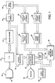
- Referring first to FIGURE 1, a block diagram of an ultrasonic diagnostic imaging system constructed in accordance with the principles of the present invention is shown. An
ultrasonic probe 10 includes amultielement transducer 12 which transmits waves of ultrasonic energy into the body of a patient and receives ultrasonic echoes returning from structures in the body. In the case of ultrasonic wave transmission for Doppler interrogation of the body, it is the echoes returning from moving tissue, blood and other fluids in the body that are of interest. Theultrasonic probe 10 is connected to a transmitter/receiver 14 which alternately pulses individual elements of the transducer to shape and steer an ultrasonic beam, and receives, amplifies and digitizes echo signals received by the transducer elements following each pulse transmission. - The transmitter/
receiver 14 is coupled to abeamformer 16 which controls the times of activation of specific elements of thetransducer 12 by the transmitter/receiver. This timing enables thetransducer 12 to transmit a shaped and focused ultrasound beam in a desired direction. Thebeamformer 16 also receives the digitized echo signals produced by the transmitter/receiver during echo reception and appropriately delays and sums them to form coherent echo signals. - The echo signals produced by the
beamformer 16 are coupled to aB mode processor 30 and an I,Q demodulator 18. The B mode processor processes the amplitude information of the echo signals on a spatial basis for the formation of a structural image of the tissue in the area of the patient being scanned. The I,Q demodulator 18 demodulates the received echo signals into quadrature components for Doppler processing. The I,Q components are filtered by awall filter 20 to remove low frequency artifacts stemming from the movement of vessel walls in applications where it is only the motion of flowing fluids such as blood that is of interest. The filtered I,Q components are then applied to a Dopplershift estimation processor 22 and a Dopplerpower estimation processor 24. - The Doppler
shift estimation processor 22 operates in the conventional manner to estimate a Doppler phase or frequency shift from the I,Q components at each sample volume location of the image field. The Doppler shift estimation processor operates on a number of signal samples resulting from the interrogation of each sample volume location by an ensemble of Doppler interrogation pulses. The sample volume values are applied to avelocity image processor 26 which maps the values to color values for display. The color values are applied to a scan converter anddisplay processor 32 which spatially arranges the color values in the desired image format. The color values are displayed as pixels on adisplay 40, wherein each color represents a particular velocity of flow in a particular direction at that pixel location. The color flow velocity information is overlaid with a structural image of the interior of the body utilizing the structural information provided by theB mode processor 30. This compound image shows both the direction and velocity of blood flow, as well as the structure of the vessels or organs which contain the flowing blood. - In accordance with the principles of the present invention the Doppler system of FIGURE 1 also includes a power Doppler imaging capability. The power Doppler components include a Doppler
power estimation processor 24 which estimates the Doppler signal power magnitude from the I,Q signal components at each sample volume location using the expression (I²+Q²)½. The Doppler power estimates at each location can be processed and displayed in real time or can be averaged with earlier acquired power estimates for each sample volume location. In a preferred embodiment, each sample volume location is interrogated by a number of pulses and theestimation processor 24 utilizes the signals obtained from all interrogations in the estimations of Doppler power at the sample volume locations. These Doppler power estimates are mapped to display intensity or color values by apower image processor 28. The display values with their spatial coordinates are stored in separate planar images in animage sequence memory 34 and are also applied to the scan converter anddisplay processor 32 which spatially arranges the Doppler power display values in the desired image format, e.g., sector or rectangular. The two dimensional Doppler power images may then be displayed on adisplay 40 or recalled from theimage sequence memory 34 for three dimensional processing using apeak detector 36 for maximum Doppler power intensity detection as discussed below. User operation of the system of FIGURE 1 is effected throughvarious user controls 42 which enable the user to select the type of imaging to be performed, i.e., B mode, color velocity Doppler or Doppler power imaging, and to store and retrieve images from theimage sequence memory 34 for three dimensional display, for example. - FIGURE 2 illustrates the use of the
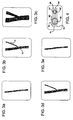
ultrasonic probe 10 to manually acquire a sequence of image planes for three dimensional display. A portion of the probe cable 11 leading to the transmitter/receiver of the ultrasound system is shown at the top of the probe. The transducer aperture of theprobe 10 is in contact with the skin of the patient over the region of the body which is to be scanned. The skin of the patient is represented by alayer 50 in the drawing. In this example the region of the patient being scanned includes ablood vessel bifurcation 52 having asmall vessel 54 branching out from alarger vessel 56. Blood is flowing inside the structural walls of the vessels as indicated at 60 and 62. - The
bifurcation 52 may be scanned by rocking or fanning theprobe 10 while it is in contact with the patient. In a preferred technique the probe aperture slides over theskin 50 as indicated byarrow 58 to scan the bifurcation region with a plurality of substantially parallel image planes. Onesuch image plane 64, here shown as a sector, is seen projecting from the transducer aperture of the probe. The relation of theimage plane 64 to the probe is denoted by animage plane marker 13 on the side of the probe case. Themarker 13 is in the same plane as theimage plane 64, and denotes the upper left side of the image in its uninverted display orientation. - In accordance with the present invention, the ultrasound system acquires and processes power Doppler information from a plurality of image planes as the probe slides over the bifurcation region of the patient as indicated by the
arrow 58. The duration of such a scan can typically last about ten to twenty seconds, during which time 100 to 200 image planes of power Doppler information are acquired, processed and stored in theimage sequence memory 34. This image information is processed to detect and record the maximum Doppler intensity at a number of different viewing angles over a range of such viewing angles as discussed below. - FIGURES 3a-3e shows a five image plane sequence which illustrates the principles of the power Doppler three dimensional imaging technique of the present invention. The five image planes of the sequence are referenced to the structure of the
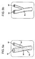
bifurcation 52 in FIGURE 4, which is a view of the top of the two vessels. FIGURE 3a is a power Doppler image taken alongplane 3a of FIGURE 4, which is seen to intersect the upper edge of the blood flow of thelarge vessel 56, just inside the vessel wall 56'. In FIGURE 3b the image plane intersects agreater cross section 72 of the blood flow of thelarge vessel 56, and theedge 74 of the blood flow of thesmall vessel 54, just inside the vessel wall 54' asplane 3b of FIGURE 4 shows. The image plane of FIGURE 3c intersects the centers of both vessel as is seen byplane 3c in FIGURE 4. In FIGURE 3d the image plane moves down to a lesser cross section of both vessels and theplane 3e of FIGURE 3e intersects only the peripheral blood flow in thelarge vessel 56. - The images of FIGURES 3a-3e are processed and presented together in a three dimensional presentation as illustrated in FIGURE 5b. The three dimensional image is seen to comprise the power Doppler information without any structural image overlay. This is clearly seen by comparing the three dimensional
power Doppler image 80 of FIGURE 5b with the similarly scaled rendering of thebifurcation 52 in FIGURE 5a. The rendering of FIGURE 5a is seen to include the structure of the vessel walls 54' and 56' which contain flowing blood indicated at 60 and 62. Thepower Doppler image 80, resulting from the Doppler detected movement of the flowing blood, is displayed without any B mode structure of the vessel walls 54' and 56'. It has been found that omitting the vessel walls from the three dimensional display does not diminish the effectiveness of the display, as the continuity of the blood flow intensity serves to define the paths in which blood is flowing. In addition, the absence of B mode echos eliminates considerable structural echo clutter from the image. The image is clearly segmented by the flow selectivity, and the smoothly varying stability and sensitivity of the maximum intensity power Doppler information. - FIGURE 8 is a flowchart illustrating a preferred technique for processing a sequence of planar Doppler power images for real time three dimensional display. As described above, the Doppler power display values with their spatial coordinates are stored in a sequence of planar images in the
image sequence memory 34, as shown bystep 80 in FIGURE 8. The images of FIGURES 3a-3e are illustrative of such a two dimensional image sequence. Instep 82 the process receives processing parameters provided by the user controls. One parameter is the range of viewing angles, θ₁-θM, over which the three dimensional presentation is to be viewed. The other parameter is the increment Δθ between each viewing angle in the range. For instance the user could input a range of viewing angles of +60o to -60o, referenced to a line of view in a plane which is normal to the plane of the first image in the sequence, and a range increment of 1o. From these inputs the number of three dimensional projections needed is computed instep 82. In this example 121 projections are needed to display a 120o range span in one degree increments. - The process now begins to form the necessary sequence of 121 maximum intensity projections. In
step 84 the planar Doppler power images are recalled from the image sequence memory for sequential processing by the scan converter anddisplay processor 32. Instep 86 each planar image is rotated to one of the viewing angles θn, then projected back to the viewing plane. Instep 88 the pixels of the projected planar images are accumulated on a maximum intensity basis. Each projected planar image is overlaid over the previously accumulated projected images but in a transposed location in the image plane which is a function of the viewing angle and the interplane spacing: the greater the viewing angle, the greater the transposition displacement from one image to the next. The display pixels chosen from the accumulated images are the maximum intensity pixels taken at each point in the image planes from all of the overlaid pixels accumulated at each point in the image. This effectively presents the maximum intensity of Doppler power seen by the viewer along every viewing line between the viewer and the three dimensional image. In a preferred embodiment the relocation of image points after rotation about the y axis, projection and transposition may be expressed as:

- After all of the planar images have been rotated, projected, transposed, overlaid, and the maximum intensities at each pixel chosen, the resulting three dimensional image for the viewing angle θn is stored in the
image sequence memory 34 as a brightness modulated monochrome image in a three dimensional image sequence. Instep 92 the process returns to step 84 and proceeds through steps 84-92 until the full three dimensional image sequence has been stored in memory. In the present example this is a sequence of 121 three dimensional images over the range of +60o to -60o. - The stored three dimensional sequence is now available for recall and display in
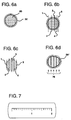
step 94 upon command of the user. As the sequence is recalled and displayed in real time, the user sees a three dimensional presentation of the motion or fluid flow occurring in the volumetric region over which the planar images were acquired. The volumetric region is viewed three dimensionally as if the user were moving around the region and viewing the motion or flow from changing viewing angles. In this particular example the user has the impression of moving over a range of viewing angles spanning 120o around the volumetric region. The viewer can sweep back and forth through the sequence, giving the impression of moving around the volumetric region in two directions. - FIGURES 6a-6d illustrate the effects of nonuniform spacing of image planes which can arise from manual image plane scanning. FIGURE 6a is a top view of the
large vessel 56, showing theblood flow 60 surrounded by the vessel wall 56' for reference. FIGURE 6b shows another sequence of five image planes taken across the vessel but unlike the sequence of FIGURE 4, these image planes are unevenly spaced.Image planes image planes 4 and 5. Such a spacing will result for instance when the probe slides faster when acquiringimage planes image planes 4 and 5. This sequence is acquired by manually sliding the probe from left to right at a progressively slower speed across the skin above thevessel 56. - In a constructed embodiment of the present invention the image planes are assumed to be evenly spaced across the imaged volume and are processed and displayed accordingly. FIGURE 6c shows the five image planes of FIGURE 6b from above when they are evenly spaced for display. The result of this spacing is more readily seen in FIGURE 6d, in which the border of the blood flow and the vessel wall 56'' have been reconnected for ease of illustration. The arrows at 78 illustrate the uniform image plane spacing, which is slightly less than the spacing of
image planes image planes 5 and 6 in that drawing. The effect is to give the cross sectional area of the blood flow a slightly oblong appearance in which the left side of the flow area is compressed and the right side extended in relation to the actual proportions of the blood flow area. - The present inventors have observed that this distortion of the aspect ratio of the three dimensional image does not noticeably detract from the effect of the overall three dimensional display. Even with such aspect distortion the three dimensional image continues to show the relative paths and orientations of blood vessels and the continuity or stenosis of flow in vessels in a manner not achieved by two dimensional presentations. The continuity of flow paths and display effectiveness is enhanced by displaying the Doppler power on the basis of the maximum signal intensity. When the image planes are acquired from a range of acquisition angles the use of the maximum intensity display has the effect of diminishing sensitivity variation resulting from Doppler angle effects. The image planes may be concurrently displayed in the form of a surface rendering or a transparency of the blood flow information, but a preferred presentation is a monochrome display of the varying brightness of the maximum intensity pixels of the combined images of a volumetric region as described above. The flow and perfusion of the blood supply in an organ such as a kidney is more completely displayed with a three dimensional power Doppler image than can be accomplished with a two dimensional presentation. The technique is well suited for assessing the success of organ transplants, for instance.
- Simple aids may be provided to improve the accuracy of manual three dimensional scanning if desired. One such aid is shown in FIGURE 7, and comprises a ruler scale printed on a clear strip of surgical tape. The tape is applied to the skin of the patient adjacent to the probe, and the probe is moved along the scale with the
marker 13 on the probe used as a reference. Image planes can be acquired at each marker on the scale, or the scale can be traversed in a given time such as twenty seconds. Other aids may also be supplied by the ultrasound system such as audible signals or lights telling the user when to start and stop movement of the probe, and when the moving probe should be passing each marker on the scale. - The imaging techniques of the present invention including particularly that of FIGURE 8 can be applied to a sequence of planar images acquired with position sensing of the image planes for display of anatomically precise images. An advantageous Doppler technique for sensing the positions of the image planes and lines in each plane in relation to each other is described in U.S. Patent number 5,127,409. When the positions of the image planes or lines are known in relation to each other the three dimensional processor no longer has to assume uniform spacing between two dimensional planes, but can utilize the measured spacing between three dimensional display elements to form more geometrically accurate three dimensional images.
Claims (18)
- A method for producing three dimensional ultrasonic images of the interior of a body comprising the steps of:
transmitting ultrasonic waves over a volumetric region of the interior of the body;
receiving ultrasonic Doppler information signals from spatial locations within said region;
processing said ultrasonic Doppler information signals to determine the Doppler power intensity received from said locations within said region; and
displaying said Doppler power intensity on a spatial basis in a three dimensional presentation. - The method of Claim 1, wherein said step of processing comprises the step of processing said ultrasonic Doppler information signals to determine the maximum Doppler power intensity received from said locations within said region; and
wherein said step of displaying comprises the step of displaying said maximum Doppler power intensity of said locations on a spatial basis in a three dimensional presentation. - The method of Claim 2, wherein said step of transmitting comprises the step of transmitting ultrasonic waves over a series of planar regions of a volumetric region of the interior of the body; and
wherein said step of receiving comprises the step of receiving ultrasonic Doppler information signals from spatial locations within said planar regions. - The method of Claim 3, wherein said step of processing comprises the step of processing said ultrasonic Doppler information signals in spatially related image planes to determine the Doppler power intensity received from said locations within each of said image planes; and
wherein the step of displaying comprises the step of concurrently displaying said Doppler power intensity of a plurality of said image planes on a spatial basis in a three dimensional presentation. - The method of Claim 4, further comprising the step of identifying the maximum Doppler power intensity at each point in a combination of said spatially related image planes; and
wherein the step of displaying comprises the step of displaying said identified maximum Doppler power intensities on a spatial basis in a three dimensional display. - The method of Claim 1, wherein said step of displaying comprises the step of displaying said Doppler power intensity on a spatial basis in the absence of structural echo information signals in a three dimensional presentation.
- The method of Claim 1, further comprising the step of providing said transmitting and receiving steps by manually moving an ultrasonic transducer probe which is in contact with said body.
- An ultrasonic diagnostic imaging system which is capable of providing three dimensional presentations of the interior of a body comprising:
an ultrasonic transducer probe for transmitting ultrasonic waves over a volumetric region of the interior of the body and for receiving ultrasonic Doppler information signals returned from spatial locations within said region;
a power Doppler processor responsive to said ultrasonic Doppler information signals for producing Doppler power intensity signals corresponding to said locations within said region;
an image processor for processing said Doppler power intensity signals for display in a three dimensional image presentation; and
a display coupled to said image processor which displays said three dimensional image presentation. - The ultrasonic diagnostic imaging system of Claim 8, wherein said image processor comprises means responsive to said Doppler power intensity signals for producing a maximum Doppler power intensity image of said region.
- The ultrasonic diagnostic imaging system of Claim 9, wherein said ultrasonic transducer probe comprises means for transmitting ultrasonic waves over a series of image planes of a volumetric region of the interior of the body and for receiving ultrasonic Doppler information signals returned from spatial locations within said image planes of said region.
- The ultrasonic diagnostic imaging system of Claim 10, wherein said image processor further comprises means for processing said Doppler power intensity signals in spatially related image planes to determine the Doppler power intensity corresponding to locations within each of said image planes; and
wherein said display further comprises means for concurrently displaying said Doppler power intensity of a plurality of said image planes on a spatial basis in a three dimensional presentation. - The ultrasonic diagnostic imaging system of Claim 11, further comprising a peak detector responsive to the Doppler power intensity determinations corresponding to locations within each of said image planes for identifying the maximum Doppler power intensity at points in a combination of a plurality of image planes; and
wherein said display comprises means for displaying maximum Doppler power intensity images in the absence of concurrent display of tissue structure. - The ultrasonic diagnostic imaging system of Claim 8, wherein said image processor further comprises means for processing said Doppler power intensity signals for display in the absence of tissue structure information signals in a three dimensional image presentation.
- The ultrasonic diagnostic imaging system of Claim 13, further comprising a peak detector responsive to said Doppler power intensity signals for identifying the maximum Doppler power intensity corresponding to said locations within said image planes.
- The ultrasonic diagnostic imaging system of Claim 14, wherein said ultrasonic transducer probe comprises a manual scanner which is manually moved in relation to said volumetric region to scan a sequence of spatially related image planes in said region.
- An ultrasonic diagnostic imaging system which is capable of providing three dimensional presentations of a region of a body comprising:
an ultrasonic transducer probe for transmitting ultrasonic waves over a sequence of image planes of said region of the body and for receiving ultrasonic Doppler information signals returned from spatial locations within said image planes while said probe is manually incremented positionally in relation to said region;
a power Doppler processor responsive to said ultrasonic Doppler information signals for estimating the Doppler power corresponding to said locations within said image planes;
an image processor for processing said Doppler power estimates to produce a maximum Doppler power image for display in a three dimensional image presentation in the absence of non Doppler signal information; and
a display responsive to the production of maximum Doppler power images which displays a sequence of said maximum Doppler power images in a three dimensional image presentation in the absence of a structural display of tissue. - The ultrasonic diagnostic imaging system of Claim 16, wherein said image processor comprises means for accumulating said estimates of Doppler power of a plurality of said image planes to form a three dimensional display image of the maximum Doppler power intensity as seen by a viewer from a given viewing perspective.
- The ultrasonic diagnostic imaging system of Claim 17, further comprising an image sequence memory for storing said estimates of Doppler power in corresponding images and for storing a sequence maximum Doppler power images.
Priority Applications (1)
| Application Number | Priority Date | Filing Date | Title |
|---|---|---|---|
| EP02077158A EP1255124B1 (en) | 1994-11-22 | 1995-11-21 | Ultrasonic diagnostic scanning for three dimensional display |
Applications Claiming Priority (2)
| Application Number | Priority Date | Filing Date | Title |
|---|---|---|---|
| US08/343,811 US5474073A (en) | 1994-11-22 | 1994-11-22 | Ultrasonic diagnostic scanning for three dimensional display |
| US343811 | 1994-11-22 |
Related Child Applications (1)
| Application Number | Title | Priority Date | Filing Date |
|---|---|---|---|
| EP02077158A Division EP1255124B1 (en) | 1994-11-22 | 1995-11-21 | Ultrasonic diagnostic scanning for three dimensional display |
Publications (3)
| Publication Number | Publication Date |
|---|---|
| EP0714036A2 true EP0714036A2 (en) | 1996-05-29 |
| EP0714036A3 EP0714036A3 (en) | 1998-01-07 |
| EP0714036B1 EP0714036B1 (en) | 2002-07-17 |
Family
ID=23347773
Family Applications (2)
| Application Number | Title | Priority Date | Filing Date |
|---|---|---|---|
| EP95308312A Expired - Lifetime EP0714036B1 (en) | 1994-11-22 | 1995-11-21 | Ultrasonic diagnostic scanning for three dimensional display |
| EP02077158A Expired - Lifetime EP1255124B1 (en) | 1994-11-22 | 1995-11-21 | Ultrasonic diagnostic scanning for three dimensional display |
Family Applications After (1)
| Application Number | Title | Priority Date | Filing Date |
|---|---|---|---|
| EP02077158A Expired - Lifetime EP1255124B1 (en) | 1994-11-22 | 1995-11-21 | Ultrasonic diagnostic scanning for three dimensional display |
Country Status (7)
| Country | Link |
|---|---|
| US (2) | US5474073A (en) |
| EP (2) | EP0714036B1 (en) |
| JP (2) | JP2812670B2 (en) |
| AT (2) | ATE506620T1 (en) |
| CA (1) | CA2157313C (en) |
| DE (2) | DE69527409T2 (en) |
| ES (1) | ES2179861T3 (en) |
Families Citing this family (127)
| Publication number | Priority date | Publication date | Assignee | Title |
|---|---|---|---|---|
| US5485842A (en) | 1994-11-30 | 1996-01-23 | Advanced Technology Laboratories, Inc. | Ultrasonic diagnostic scan conversion for three dimensional display processing |
| US5608690A (en) * | 1995-03-02 | 1997-03-04 | Acuson Corporation | Transmit beamformer with frequency dependent focus |
| JPH08299342A (en) * | 1995-05-15 | 1996-11-19 | Toshiba Corp | Ultrasonic diagnostic device |
| WO1997000482A1 (en) * | 1995-06-15 | 1997-01-03 | The Regents Of The University Of Michigan | Method and apparatus for composition and display of three-dimensional image from two-dimensional ultrasound |
| DE69634112T2 (en) * | 1995-10-10 | 2005-12-08 | Advanced Technology Laboratories, Inc., Bothell | Ultrasound imaging for diagnostics using contrast agents |
| US5833613A (en) * | 1996-09-27 | 1998-11-10 | Advanced Technology Laboratories, Inc. | Ultrasonic diagnostic imaging with contrast agents |
| EP0883860B1 (en) | 1996-02-29 | 2006-08-23 | Acuson Corporation | Multiple ultrasound image registration system, method and transducer |
| US5669385A (en) * | 1996-03-13 | 1997-09-23 | Advanced Technology Laboratories, Inc. | Ultrasonic scanning of tissue motion in three dimensions |
| KR19990014883A (en) * | 1996-03-18 | 1999-02-25 | 구니토모 시게 | Ultrasonic Diagnostic Device |
| US5720291A (en) * | 1996-03-22 | 1998-02-24 | Advanced Technology Laboratories, Inc. | Three dimensional medical ultrasonic diagnostic image of tissue texture and vasculature |
| US5645066A (en) * | 1996-04-26 | 1997-07-08 | Advanced Technology Laboratories, Inc. | Medical ultrasonic diagnostic imaging system with scanning guide for three dimensional imaging |
| JP3361692B2 (en) * | 1996-05-10 | 2003-01-07 | ジーイー横河メディカルシステム株式会社 | Ultrasound diagnostic equipment |
| JPH09299368A (en) * | 1996-05-16 | 1997-11-25 | Aloka Co Ltd | Ultrasonic diagnostic device |
| US5911691A (en) * | 1996-05-21 | 1999-06-15 | Aloka Co., Ltd. | Ultrasound image processing apparatus and method of forming and displaying ultrasound images by the apparatus |
| US5860929A (en) * | 1996-06-07 | 1999-01-19 | The Regents Of The University Of Michigan | Fractional moving blood volume estimation with power doppler ultrasound |
| JP3365929B2 (en) * | 1996-10-07 | 2003-01-14 | ジーイー横河メディカルシステム株式会社 | Image processing method and image processing apparatus |
| US5871447A (en) * | 1996-11-07 | 1999-02-16 | Acuson Corporation | Doppler energy-related parameters in an ultrasound imaging system |
| US5846200A (en) | 1996-11-08 | 1998-12-08 | Advanced Technology Laboratories, Inc. | Ultrasonic diagnostic imaging system for analysis of left ventricular function |
| US5860924A (en) * | 1996-11-26 | 1999-01-19 | Advanced Technology Laboratories, Inc. | Three dimensional ultrasonic diagnostic image rendering from tissue and flow images |
| EP0851241B1 (en) | 1996-11-26 | 2006-05-24 | ATL Ultrasound, Inc. | Ultrasonic diagnostic imaging of response frequency differing from transmit frequency |
| US6059728A (en) * | 1997-01-02 | 2000-05-09 | Storz Instrument Co. | Three-dimensional ultrasound imaging system and probe |
| US6045508A (en) | 1997-02-27 | 2000-04-04 | Acuson Corporation | Ultrasonic probe, system and method for two-dimensional imaging or three-dimensional reconstruction |
| US5899863A (en) * | 1997-05-07 | 1999-05-04 | General Electric Company | Method and apparatus for segmenting B-mode intensity data using doppler shift data in three-dimensional ultrasound imaging |
| US5840032A (en) * | 1997-05-07 | 1998-11-24 | General Electric Company | Method and apparatus for three-dimensional ultrasound imaging using transducer array having uniform elevation beamwidth |
| US6126603A (en) * | 1997-05-07 | 2000-10-03 | General Electric Company | Method and apparatus for segmenting color flow mode data using velocity information in three-dimensional ultrasound imaging |
| US5865750A (en) * | 1997-05-07 | 1999-02-02 | General Electric Company | Method and apparatus for enhancing segmentation in three-dimensional ultrasound imaging |
| US5779641A (en) * | 1997-05-07 | 1998-07-14 | General Electric Company | Method and apparatus for three-dimensional ultrasound imaging by projecting filtered pixel data |
| US6102864A (en) * | 1997-05-07 | 2000-08-15 | General Electric Company | Three-dimensional ultrasound imaging of velocity and power data using average or median pixel projections |
| US5904653A (en) * | 1997-05-07 | 1999-05-18 | General Electric Company | Method and apparatus for three-dimensional ultrasound imaging combining intensity data with color flow velocity or power data |
| US5954653A (en) * | 1997-05-07 | 1999-09-21 | General Electric Company | Method and apparatus for automatically enhancing contrast in projected ultrasound image |
| US5865753A (en) * | 1997-05-27 | 1999-02-02 | Friauf; Walter S. | Coherent detection ultrasound system |
| US5916168A (en) * | 1997-05-29 | 1999-06-29 | Advanced Technology Laboratories, Inc. | Three dimensional M-mode ultrasonic diagnostic imaging system |
| US6117080A (en) | 1997-06-04 | 2000-09-12 | Atl Ultrasound | Ultrasonic imaging apparatus and method for breast cancer diagnosis with the use of volume rendering |
| US5876342A (en) * | 1997-06-30 | 1999-03-02 | Siemens Medical Systems, Inc. | System and method for 3-D ultrasound imaging and motion estimation |
| US5928151A (en) * | 1997-08-22 | 1999-07-27 | Acuson Corporation | Ultrasonic system and method for harmonic imaging in three dimensions |
| US5957138A (en) * | 1997-08-25 | 1999-09-28 | Diasonics Ultrasound, Inc. | Method and apparatus for three-dimensional flow lumen imaging |
| JPH1189837A (en) * | 1997-09-19 | 1999-04-06 | Fujitsu Ltd | Ultrasonograph |
| JPH11221211A (en) | 1997-11-25 | 1999-08-17 | Atl Ultrasound Inc | Scan auxiliary for three-dimensional ultrasonography |
| US6171244B1 (en) | 1997-12-31 | 2001-01-09 | Acuson Corporation | Ultrasonic system and method for storing data |
| US6262749B1 (en) | 1997-12-31 | 2001-07-17 | Acuson Corporation | Ultrasonic system and method for data transfer, storage and/or processing |
| US5971923A (en) * | 1997-12-31 | 1999-10-26 | Acuson Corporation | Ultrasound system and method for interfacing with peripherals |
| US6116244A (en) * | 1998-06-02 | 2000-09-12 | Acuson Corporation | Ultrasonic system and method for three-dimensional imaging with opacity control |
| US6511426B1 (en) | 1998-06-02 | 2003-01-28 | Acuson Corporation | Medical diagnostic ultrasound system and method for versatile processing |
| US6241675B1 (en) | 1998-06-09 | 2001-06-05 | Volumetrics Medical Imaging | Methods and systems for determining velocity of tissue using three dimensional ultrasound data |
| US7837624B1 (en) | 1998-11-20 | 2010-11-23 | Siemens Medical Solutions Usa, Inc. | Medical diagnostic ultrasound imaging methods for extended field of view |
| US6080108A (en) * | 1998-11-17 | 2000-06-27 | Atl Ultrasound, Inc. | Scanning aid for quantified three dimensional ultrasonic diagnostic imaging |
| US6364835B1 (en) | 1998-11-20 | 2002-04-02 | Acuson Corporation | Medical diagnostic ultrasound imaging methods for extended field of view |
| US6554770B1 (en) | 1998-11-20 | 2003-04-29 | Acuson Corporation | Medical diagnostic ultrasound imaging methods for extended field of view |
| US6176828B1 (en) * | 1998-12-24 | 2001-01-23 | General Electric Company | Method and apparatus for optimal data mapping of power doppler images |
| US6071241A (en) * | 1998-12-31 | 2000-06-06 | General Electric Company | Ultrasound color flow display optimization by adjustment of threshold using sampling |
| US6231508B1 (en) * | 1999-03-05 | 2001-05-15 | Atl Ultrasound | Ultrasonic diagnostic imaging system with digital video image marking |
| US6213944B1 (en) | 1999-03-05 | 2001-04-10 | Atl Ultrasound, Inc. | Ultrasonic diagnostic imaging system with a digital video recorder with visual controls |
| US6231510B1 (en) * | 1999-03-05 | 2001-05-15 | Atl Ultrasound | Ultrasonic diagnostic imaging system |
| US6377514B1 (en) * | 1999-04-06 | 2002-04-23 | Q-Dot, Inc. | Acoustic lens-based swimmer's sonar |
| US6234968B1 (en) | 1999-06-15 | 2001-05-22 | Acuson Corporation | 3-D diagnostic medical ultrasound imaging using a 1-D array |
| US6190321B1 (en) | 1999-08-06 | 2001-02-20 | Acuson Corporation | Medical diagnostic ultrasound imaging methods for estimating motion between composite ultrasonic images and recovering color doppler values from composite images |
| US6254539B1 (en) | 1999-08-26 | 2001-07-03 | Acuson Corporation | Transducer motion compensation in medical diagnostic ultrasound 3-D imaging |
| JP3696763B2 (en) | 1999-11-05 | 2005-09-21 | ジーイー・メディカル・システムズ・グローバル・テクノロジー・カンパニー・エルエルシー | Ultrasound imaging device |
| US6482161B1 (en) | 2000-06-29 | 2002-11-19 | Acuson Corporation | Medical diagnostic ultrasound system and method for vessel structure analysis |
| US6517488B1 (en) | 2000-06-29 | 2003-02-11 | Acuson Corporation | Medical diagnostic ultrasound system and method for identifying constrictions |
| US6503202B1 (en) | 2000-06-29 | 2003-01-07 | Acuson Corp. | Medical diagnostic ultrasound system and method for flow analysis |
| US7024024B1 (en) | 2000-11-14 | 2006-04-04 | Axle International | System for contrast echo analysis |
| JP3844663B2 (en) * | 2001-05-07 | 2006-11-15 | ジーイー・メディカル・システムズ・グローバル・テクノロジー・カンパニー・エルエルシー | Ultrasonic diagnostic equipment |
| JP4837206B2 (en) * | 2001-09-21 | 2011-12-14 | ジーイー・メディカル・システムズ・グローバル・テクノロジー・カンパニー・エルエルシー | Ultrasonic imaging method and ultrasonic diagnostic apparatus |
| US6692438B2 (en) | 2001-12-18 | 2004-02-17 | Koninklijke Philips Electronics Nv | Ultrasonic imaging system and method for displaying tissue perfusion and other parameters varying with time |
| US20050075567A1 (en) * | 2001-12-18 | 2005-04-07 | Koninklijke Philips Electronics N.V. | Ultrasonic diagnostic imaging system with assisted border tracing |
| US6723050B2 (en) | 2001-12-19 | 2004-04-20 | Koninklijke Philips Electronics N.V. | Volume rendered three dimensional ultrasonic images with polar coordinates |
| AU2003278424A1 (en) * | 2002-11-06 | 2004-06-07 | Koninklijke Philips Electronics N.V. | Phased array acoustic system for 3d imaging of moving parts_____ |
| WO2005033737A1 (en) * | 2003-09-30 | 2005-04-14 | Koninklijke Philips Electronics N.V. | Clutter filtering with small ensemble lengths in ultrasound imaging |
| WO2005044108A1 (en) | 2003-11-07 | 2005-05-19 | Koninklijke Philips Electronics, N.V. | System and method for ultrasound perfusion imaging |
| US20070055161A1 (en) * | 2003-12-03 | 2007-03-08 | Koninklijke Philips Electronics N.V. | Ultrasonic imaging system and method for simulataneous display of blood flow and perfusion parameters |
| ATE487149T1 (en) * | 2003-12-16 | 2010-11-15 | Koninkl Philips Electronics Nv | DIAGNOSTIC ULTRASONIC IMAGING METHOD AND SYSTEM WITH AUTOMATIC CONTROL OF RESOLUTION AND IMAGE RATE |
| CN1893878A (en) * | 2003-12-16 | 2007-01-10 | 株式会社日立医药 | Ultrasonographic bio-movement detection device, image presentation device using the same, and ultrasonographic curing device |
| US7403811B2 (en) * | 2004-03-01 | 2008-07-22 | Scimed Life Systems, Inc. | Method of catheter tracking using image information |
| US20060004291A1 (en) * | 2004-06-22 | 2006-01-05 | Andreas Heimdal | Methods and apparatus for visualization of quantitative data on a model |
| US8244332B2 (en) * | 2004-12-22 | 2012-08-14 | Siemens Medical Solutions Usa, Inc. | Three-dimensional breast anatomy imaging system |
| US8834371B2 (en) * | 2005-03-31 | 2014-09-16 | Kabushiki Kaisha Toshiba | Ultrasound diagnostic apparatus and ultrasound image processing program |
| CN101326447A (en) | 2005-12-14 | 2008-12-17 | 皇家飞利浦电子股份有限公司 | Doppler detection of pulsatile blood flow |
| JP2007319492A (en) * | 2006-06-02 | 2007-12-13 | Shimadzu Corp | Ultrasonograph |
| WO2008003127A1 (en) * | 2006-07-07 | 2008-01-10 | Signostics Pty Ltd | Improved acoustic imaging method and apparatus |
| WO2008010135A2 (en) | 2006-07-14 | 2008-01-24 | Koninklijke Philips Electronics, N.V. | System and method for organizing, recording and displaying images in ultrasound imaging systems |
| US7728868B2 (en) | 2006-08-02 | 2010-06-01 | Inneroptic Technology, Inc. | System and method of providing real-time dynamic imagery of a medical procedure site using multiple modalities |
| JP5450065B2 (en) * | 2006-08-11 | 2014-03-26 | コーニンクレッカ フィリップス エヌ ヴェ | Ultrasound system for cerebral blood flow imaging and clot lysis using microbubbles |
| EP2051778A2 (en) | 2006-08-11 | 2009-04-29 | Koninklijke Philips Electronics N.V. | Ultrasound system for cerebral blood flow imaging and microbubble-enhanced blood clot lysis |
| JP5160825B2 (en) * | 2007-07-17 | 2013-03-13 | 日立アロカメディカル株式会社 | Ultrasonic diagnostic apparatus and image processing program |
| JP5226978B2 (en) * | 2007-07-17 | 2013-07-03 | 日立アロカメディカル株式会社 | Ultrasonic diagnostic apparatus and image processing program |
| WO2009094646A2 (en) | 2008-01-24 | 2009-07-30 | The University Of North Carolina At Chapel Hill | Methods, systems, and computer readable media for image guided ablation |
| US9089278B2 (en) * | 2008-07-10 | 2015-07-28 | Koninklijke Philips N.V. | Ultrasonic assessment of cardiac synchronicity and viability |
| US8554307B2 (en) | 2010-04-12 | 2013-10-08 | Inneroptic Technology, Inc. | Image annotation in image-guided medical procedures |
| US8641621B2 (en) | 2009-02-17 | 2014-02-04 | Inneroptic Technology, Inc. | Systems, methods, apparatuses, and computer-readable media for image management in image-guided medical procedures |
| US8690776B2 (en) | 2009-02-17 | 2014-04-08 | Inneroptic Technology, Inc. | Systems, methods, apparatuses, and computer-readable media for image guided surgery |
| US11464578B2 (en) | 2009-02-17 | 2022-10-11 | Inneroptic Technology, Inc. | Systems, methods, apparatuses, and computer-readable media for image management in image-guided medical procedures |
| WO2011041244A1 (en) | 2009-10-01 | 2011-04-07 | Koninklijke Philips Electronics, N.V. | Contrast-enhanced ultrasound assessment of liver blood flow for monitoring liver therapy |
| KR100977367B1 (en) * | 2009-10-28 | 2010-08-20 | (주)메디슨 | Three dimension pulsed wave spectrum ultrasonic diagnostic apparatus and three dimension pulsed wave spectrum data generate method |
| WO2011117788A1 (en) | 2010-03-23 | 2011-09-29 | Koninklijke Philips Electronics N.V. | Volumetric ultrasound image data reformatted as an image plane sequence |
| US8582865B2 (en) * | 2010-04-28 | 2013-11-12 | General Electric Company | Ultrasound imaging with ray casting and software-based image reconstruction |
| WO2012049586A2 (en) | 2010-10-11 | 2012-04-19 | Koninklijke Philips Electronics N.V. | Micro-particulate identification and classification in ultrasound images |
| JP5721462B2 (en) * | 2011-02-09 | 2015-05-20 | キヤノン株式会社 | Subject information acquisition device |
| JP2012235827A (en) * | 2011-05-10 | 2012-12-06 | Omori Kogyo:Kk | Ultrasonic examination method and examination assisting tool |
| US8670816B2 (en) | 2012-01-30 | 2014-03-11 | Inneroptic Technology, Inc. | Multiple medical device guidance |
| EP2852849B1 (en) | 2012-05-22 | 2020-08-05 | Koninklijke Philips N.V. | Ultrasound image display set-up for remote display terminal |
| RU2015111740A (en) | 2012-09-01 | 2016-10-20 | Конинклейке Филипс Н.В. | ULTRASONIC VOLUME FLOW MEASUREMENT FOR ABLATION THERAPY |
| CN104582585B (en) | 2012-09-01 | 2017-09-26 | 皇家飞利浦有限公司 | Ultrasonic volume flow measurement for melting planning |
| BR112015014308B1 (en) * | 2012-12-21 | 2022-10-11 | Koninklijke Philips N.V | APPARATUS AND METHOD FOR GUIDING A USER HANDLING AN IMAGING PROBE |
| CN103971356B (en) * | 2013-02-04 | 2017-09-08 | 腾讯科技(深圳)有限公司 | Street view image Target Segmentation method and device based on parallax information |
| US10314559B2 (en) | 2013-03-14 | 2019-06-11 | Inneroptic Technology, Inc. | Medical device guidance |
| EP3024397B1 (en) * | 2013-07-24 | 2017-12-20 | Koninklijke Philips N.V. | Method for aligning spatially different subvolumes of ultrasonic data of a blood vessel |
| WO2015011585A1 (en) * | 2013-07-24 | 2015-01-29 | Koninklijke Philips N.V. | Non-imaging two dimensional array probe and system for classifying carotid stenosis |
| US11090029B2 (en) * | 2013-07-24 | 2021-08-17 | Koninklijke Philips N.V. | System for automated screening of carotid stenosis |
| WO2015087203A1 (en) | 2013-12-13 | 2015-06-18 | Koninklijke Philips N.V. | Imaging systems and methods for monitoring treatment of tissue lesions |
| WO2015092628A1 (en) | 2013-12-20 | 2015-06-25 | Koninklijke Philips N.V. | Ultrasound imaging systems and methods for tracking locations of an invasive medical device |
| US9901406B2 (en) | 2014-10-02 | 2018-02-27 | Inneroptic Technology, Inc. | Affected region display associated with a medical device |
| WO2016055902A1 (en) | 2014-10-09 | 2016-04-14 | Koninklijke Philips N.V. | Three dimensional ultrasound imaging by intersecting 2d scanning |
| US10188467B2 (en) | 2014-12-12 | 2019-01-29 | Inneroptic Technology, Inc. | Surgical guidance intersection display |
| CN107427279B (en) | 2015-03-10 | 2022-07-29 | 皇家飞利浦有限公司 | Ultrasonic diagnosis of cardiac function using a heart model chamber with user control |
| CN107427282A (en) | 2015-03-10 | 2017-12-01 | 皇家飞利浦有限公司 | Ultrasonic Diagnosis to cardiac function is split by single-degree-of-freedom chamber |
| US9949700B2 (en) | 2015-07-22 | 2018-04-24 | Inneroptic Technology, Inc. | Medical device approaches |
| CN105232086A (en) * | 2015-10-29 | 2016-01-13 | 深圳市德力凯医疗设备股份有限公司 | Transcranial Doppler intracranial blood flow three dimensional information display method and system |
| US11694412B2 (en) | 2015-12-02 | 2023-07-04 | Koninklijke Philips N.V. | Ultrasonic cardiac assessment of hearts with medial axis curvature and transverse eccentricity |
| US9675319B1 (en) | 2016-02-17 | 2017-06-13 | Inneroptic Technology, Inc. | Loupe display |
| CN108778142B (en) | 2016-03-01 | 2023-03-28 | 皇家飞利浦有限公司 | Automatic ultrasonic measurement of neck fold translucent band |
| CN105769303B (en) * | 2016-05-06 | 2019-04-30 | 广州医谷生物医疗科技有限公司 | A kind of visual Arterial puncture intubation device |
| US10278778B2 (en) | 2016-10-27 | 2019-05-07 | Inneroptic Technology, Inc. | Medical device navigation using a virtual 3D space |
| US20190329075A1 (en) | 2016-12-07 | 2019-10-31 | Koninklijke Philips N.V. | Ultrasonic sonothrombolysis treatment planning |
| US11259879B2 (en) | 2017-08-01 | 2022-03-01 | Inneroptic Technology, Inc. | Selective transparency to assist medical device navigation |
| US11484365B2 (en) | 2018-01-23 | 2022-11-01 | Inneroptic Technology, Inc. | Medical image guidance |
| EP3669786A1 (en) * | 2018-12-17 | 2020-06-24 | Koninklijke Philips N.V. | Systems and methods for guided ultrasound data acquisition |
Citations (3)
| Publication number | Priority date | Publication date | Assignee | Title |
|---|---|---|---|---|
| EP0383288A1 (en) * | 1989-02-16 | 1990-08-22 | Fujitsu Limited | Ultrasound diagnostic equipment for characterising tissue by analysis of backscatter |
| US5329929A (en) * | 1991-08-26 | 1994-07-19 | Kabushiki Kaisha Toshiba | Ultrasonic diagnostic apparatus |
| US5365929A (en) * | 1993-10-04 | 1994-11-22 | Advanced Technology Laboratories, Inc. | Multiple sample volume spectral Doppler |
Family Cites Families (6)
| Publication number | Priority date | Publication date | Assignee | Title |
|---|---|---|---|---|
| US4058001A (en) * | 1976-08-02 | 1977-11-15 | G. D. Searle & Co. | Ultrasound imaging system with improved scan conversion |
| US5159931A (en) * | 1988-11-25 | 1992-11-03 | Riccardo Pini | Apparatus for obtaining a three-dimensional reconstruction of anatomic structures through the acquisition of echographic images |
| DE3914619A1 (en) * | 1989-05-03 | 1990-11-08 | Kontron Elektronik | DEVICE FOR TRANSOESOPHAGEAL ECHOCARDIOGRAPHY |
| US5315512A (en) * | 1989-09-01 | 1994-05-24 | Montefiore Medical Center | Apparatus and method for generating image representations of a body utilizing an ultrasonic imaging subsystem and a three-dimensional digitizer subsystem |
| GB9025431D0 (en) * | 1990-11-22 | 1991-01-09 | Advanced Tech Lab | Three dimensional ultrasonic imaging |
| US5282471A (en) * | 1991-07-31 | 1994-02-01 | Kabushiki Kaisha Toshiba | Ultrasonic imaging system capable of displaying 3-dimensional angiogram in real time mode |
-
1994
- 1994-11-22 US US08/343,811 patent/US5474073A/en not_active Ceased
-
1995
- 1995-08-31 CA CA002157313A patent/CA2157313C/en not_active Expired - Fee Related
- 1995-11-21 EP EP95308312A patent/EP0714036B1/en not_active Expired - Lifetime
- 1995-11-21 DE DE69527409T patent/DE69527409T2/en not_active Expired - Lifetime
- 1995-11-21 AT AT02077158T patent/ATE506620T1/en not_active IP Right Cessation
- 1995-11-21 JP JP7325227A patent/JP2812670B2/en not_active Expired - Lifetime
- 1995-11-21 AT AT95308312T patent/ATE220801T1/en not_active IP Right Cessation
- 1995-11-21 DE DE69536158T patent/DE69536158D1/en not_active Expired - Lifetime
- 1995-11-21 EP EP02077158A patent/EP1255124B1/en not_active Expired - Lifetime
- 1995-11-21 ES ES95308312T patent/ES2179861T3/en not_active Expired - Lifetime
-
1997
- 1997-11-26 US US08/979,497 patent/USRE36564E/en not_active Expired - Lifetime
-
1998
- 1998-05-11 JP JP10127042A patent/JPH10309279A/en active Pending
Patent Citations (3)
| Publication number | Priority date | Publication date | Assignee | Title |
|---|---|---|---|---|
| EP0383288A1 (en) * | 1989-02-16 | 1990-08-22 | Fujitsu Limited | Ultrasound diagnostic equipment for characterising tissue by analysis of backscatter |
| US5329929A (en) * | 1991-08-26 | 1994-07-19 | Kabushiki Kaisha Toshiba | Ultrasonic diagnostic apparatus |
| US5365929A (en) * | 1993-10-04 | 1994-11-22 | Advanced Technology Laboratories, Inc. | Multiple sample volume spectral Doppler |
Also Published As
| Publication number | Publication date |
|---|---|
| EP1255124B1 (en) | 2011-04-20 |
| CA2157313A1 (en) | 1996-05-23 |
| ES2179861T3 (en) | 2003-02-01 |
| CA2157313C (en) | 1999-01-12 |
| USRE36564E (en) | 2000-02-08 |
| EP0714036A3 (en) | 1998-01-07 |
| ATE506620T1 (en) | 2011-05-15 |
| EP1255124A2 (en) | 2002-11-06 |
| EP0714036B1 (en) | 2002-07-17 |
| ATE220801T1 (en) | 2002-08-15 |
| DE69527409T2 (en) | 2003-02-20 |
| DE69527409D1 (en) | 2002-08-22 |
| US5474073A (en) | 1995-12-12 |
| JP2812670B2 (en) | 1998-10-22 |
| DE69536158D1 (en) | 2011-06-01 |
| JPH10309279A (en) | 1998-11-24 |
| EP1255124A3 (en) | 2002-11-13 |
| JPH08229038A (en) | 1996-09-10 |
Similar Documents
| Publication | Publication Date | Title |
|---|---|---|
| US5474073A (en) | Ultrasonic diagnostic scanning for three dimensional display | |
| US5485842A (en) | Ultrasonic diagnostic scan conversion for three dimensional display processing | |
| EP0795296B1 (en) | Ultrasonic scanning of tissue motion in three dimensions | |
| US6966878B2 (en) | Method and apparatus for obtaining a volumetric scan of a periodically moving object | |
| US6102864A (en) | Three-dimensional ultrasound imaging of velocity and power data using average or median pixel projections | |
| US6048312A (en) | Method and apparatus for three-dimensional ultrasound imaging of biopsy needle | |
| EP0882426B1 (en) | Ultrasonic imaging apparatus and method for breast examination | |
| EP1189074B1 (en) | Method and apparatus for locking sample volume onto moving vessel in pulsed doppler ultrasound imaging | |
| EP1697759B1 (en) | Ultrasonic diagnostic imaging method and system with an automatic control of resolution and frame rate | |
| US7347820B2 (en) | Phased array acoustic system for 3D imaging of moving parts | |
| US5971927A (en) | Ultrasonic diagnostic apparatus for obtaining blood data | |
| US6068598A (en) | Method and apparatus for automatic Doppler angle estimation in ultrasound imaging | |
| US5961462A (en) | Ultrasonic doppler imaging at high frame rates of display | |
| EP1579244B1 (en) | Segmentation tool for identifying flow regions in an imaging system | |
| EP0952463B1 (en) | Apparatus for three-dimensional ultrasound imaging using contrast agents and harmonic echoes | |
| EP1121901A9 (en) | Angle independent ultrasound volume flow measurement | |
| EP1006369B1 (en) | Method and apparatus for adaptive filtering by counting acoustic sample zeroes in ultrasound imaging | |
| Wells | Technical introduction to echocardiography |
Legal Events
| Date | Code | Title | Description |
|---|---|---|---|
| PUAI | Public reference made under article 153(3) epc to a published international application that has entered the european phase |
Free format text: ORIGINAL CODE: 0009012 |
|
| AK | Designated contracting states |
Kind code of ref document: A2 Designated state(s): AT BE CH DE DK ES FR GB GR IE IT LI LU MC NL PT SE |
|
| PUAL | Search report despatched |
Free format text: ORIGINAL CODE: 0009013 |
|
| AK | Designated contracting states |
Kind code of ref document: A3 Designated state(s): AT BE CH DE DK ES FR GB GR IE IT LI LU MC NL PT SE |
|
| 17P | Request for examination filed |
Effective date: 19980616 |
|
| 17Q | First examination report despatched |
Effective date: 20000202 |
|
| GRAG | Despatch of communication of intention to grant |
Free format text: ORIGINAL CODE: EPIDOS AGRA |
|
| GRAG | Despatch of communication of intention to grant |
Free format text: ORIGINAL CODE: EPIDOS AGRA |
|
| GRAH | Despatch of communication of intention to grant a patent |
Free format text: ORIGINAL CODE: EPIDOS IGRA |
|
| GRAH | Despatch of communication of intention to grant a patent |
Free format text: ORIGINAL CODE: EPIDOS IGRA |
|
| GRAA | (expected) grant |
Free format text: ORIGINAL CODE: 0009210 |
|
| AK | Designated contracting states |
Kind code of ref document: B1 Designated state(s): AT BE CH DE DK ES FR GB GR IE IT LI LU MC NL PT SE |
|
| PG25 | Lapsed in a contracting state [announced via postgrant information from national office to epo] |
Ref country code: NL Free format text: LAPSE BECAUSE OF FAILURE TO SUBMIT A TRANSLATION OF THE DESCRIPTION OR TO PAY THE FEE WITHIN THE PRESCRIBED TIME-LIMIT Effective date: 20020717 Ref country code: GR Free format text: LAPSE BECAUSE OF FAILURE TO SUBMIT A TRANSLATION OF THE DESCRIPTION OR TO PAY THE FEE WITHIN THE PRESCRIBED TIME-LIMIT Effective date: 20020717 Ref country code: BE Free format text: LAPSE BECAUSE OF FAILURE TO SUBMIT A TRANSLATION OF THE DESCRIPTION OR TO PAY THE FEE WITHIN THE PRESCRIBED TIME-LIMIT Effective date: 20020717 |
|
| REF | Corresponds to: |
Ref document number: 220801 Country of ref document: AT Date of ref document: 20020815 Kind code of ref document: T |
|
| REG | Reference to a national code |
Ref country code: GB Ref legal event code: FG4D |
|
| REG | Reference to a national code |
Ref country code: CH Ref legal event code: EP |
|
| REG | Reference to a national code |
Ref country code: IE Ref legal event code: FG4D |
|
| REF | Corresponds to: |
Ref document number: 69527409 Country of ref document: DE Date of ref document: 20020822 |
|
| PG25 | Lapsed in a contracting state [announced via postgrant information from national office to epo] |
Ref country code: SE Free format text: LAPSE BECAUSE OF FAILURE TO SUBMIT A TRANSLATION OF THE DESCRIPTION OR TO PAY THE FEE WITHIN THE PRESCRIBED TIME-LIMIT Effective date: 20021017 Ref country code: PT Free format text: LAPSE BECAUSE OF FAILURE TO SUBMIT A TRANSLATION OF THE DESCRIPTION OR TO PAY THE FEE WITHIN THE PRESCRIBED TIME-LIMIT Effective date: 20021017 Ref country code: DK Free format text: LAPSE BECAUSE OF FAILURE TO SUBMIT A TRANSLATION OF THE DESCRIPTION OR TO PAY THE FEE WITHIN THE PRESCRIBED TIME-LIMIT Effective date: 20021017 |
|
| PG25 | Lapsed in a contracting state [announced via postgrant information from national office to epo] |
Ref country code: LU Free format text: LAPSE BECAUSE OF NON-PAYMENT OF DUE FEES Effective date: 20021121 Ref country code: IE Free format text: LAPSE BECAUSE OF NON-PAYMENT OF DUE FEES Effective date: 20021121 |
|
| ET | Fr: translation filed | ||
| NLV1 | Nl: lapsed or annulled due to failure to fulfill the requirements of art. 29p and 29m of the patents act | ||
| REG | Reference to a national code |
Ref country code: ES Ref legal event code: FG2A Ref document number: 2179861 Country of ref document: ES Kind code of ref document: T3 |
|
| PLBE | No opposition filed within time limit |
Free format text: ORIGINAL CODE: 0009261 |
|
| STAA | Information on the status of an ep patent application or granted ep patent |
Free format text: STATUS: NO OPPOSITION FILED WITHIN TIME LIMIT |
|
| PG25 | Lapsed in a contracting state [announced via postgrant information from national office to epo] |
Ref country code: MC Free format text: LAPSE BECAUSE OF NON-PAYMENT OF DUE FEES Effective date: 20030601 |
|
| 26N | No opposition filed |
Effective date: 20030422 |
|
| REG | Reference to a national code |
Ref country code: IE Ref legal event code: MM4A |
|
| PGFP | Annual fee paid to national office [announced via postgrant information from national office to epo] |
Ref country code: CH Payment date: 20070227 Year of fee payment: 12 |
|
| PGFP | Annual fee paid to national office [announced via postgrant information from national office to epo] |
Ref country code: ES Payment date: 20071112 Year of fee payment: 13 |
|
| PGFP | Annual fee paid to national office [announced via postgrant information from national office to epo] |
Ref country code: AT Payment date: 20071126 Year of fee payment: 13 Ref country code: IT Payment date: 20071029 Year of fee payment: 13 |
|
| PGFP | Annual fee paid to national office [announced via postgrant information from national office to epo] |
Ref country code: GB Payment date: 20071218 Year of fee payment: 13 |
|
| PG25 | Lapsed in a contracting state [announced via postgrant information from national office to epo] |
Ref country code: LI Free format text: LAPSE BECAUSE OF NON-PAYMENT OF DUE FEES Effective date: 20071130 Ref country code: CH Free format text: LAPSE BECAUSE OF NON-PAYMENT OF DUE FEES Effective date: 20071130 |
|
| REG | Reference to a national code |
Ref country code: CH Ref legal event code: PL |
|
| GBPC | Gb: european patent ceased through non-payment of renewal fee |
Effective date: 20081121 |
|
| PG25 | Lapsed in a contracting state [announced via postgrant information from national office to epo] |
Ref country code: IT Free format text: LAPSE BECAUSE OF NON-PAYMENT OF DUE FEES Effective date: 20081121 Ref country code: AT Free format text: LAPSE BECAUSE OF NON-PAYMENT OF DUE FEES Effective date: 20081121 |
|
| PG25 | Lapsed in a contracting state [announced via postgrant information from national office to epo] |
Ref country code: GB Free format text: LAPSE BECAUSE OF NON-PAYMENT OF DUE FEES Effective date: 20081121 |
|
| REG | Reference to a national code |
Ref country code: ES Ref legal event code: FD2A Effective date: 20081122 |
|
| PG25 | Lapsed in a contracting state [announced via postgrant information from national office to epo] |
Ref country code: ES Free format text: LAPSE BECAUSE OF NON-PAYMENT OF DUE FEES Effective date: 20081122 |
|
| PGFP | Annual fee paid to national office [announced via postgrant information from national office to epo] |
Ref country code: FR Payment date: 20141126 Year of fee payment: 20 |
|
| PGFP | Annual fee paid to national office [announced via postgrant information from national office to epo] |
Ref country code: DE Payment date: 20150129 Year of fee payment: 20 |
|
| REG | Reference to a national code |
Ref country code: DE Ref legal event code: R071 Ref document number: 69527409 Country of ref document: DE |