EP0713951A2 - Verfahren zum Bohren und Komplettieren von Bohrlöchern - Google Patents
Verfahren zum Bohren und Komplettieren von Bohrlöchern Download PDFInfo
- Publication number
- EP0713951A2 EP0713951A2 EP95118242A EP95118242A EP0713951A2 EP 0713951 A2 EP0713951 A2 EP 0713951A2 EP 95118242 A EP95118242 A EP 95118242A EP 95118242 A EP95118242 A EP 95118242A EP 0713951 A2 EP0713951 A2 EP 0713951A2
- Authority
- EP
- European Patent Office
- Prior art keywords
- drilling
- bit
- well
- assembly
- bore hole
- Prior art date
- Legal status (The legal status is an assumption and is not a legal conclusion. Google has not performed a legal analysis and makes no representation as to the accuracy of the status listed.)
- Withdrawn
Links
- 238000005553 drilling Methods 0.000 title claims abstract description 83
- 238000000034 method Methods 0.000 title claims abstract description 29
- 238000004519 manufacturing process Methods 0.000 claims abstract description 37
- 239000012530 fluid Substances 0.000 claims abstract description 21
- 238000002955 isolation Methods 0.000 claims abstract description 4
- 239000004576 sand Substances 0.000 claims description 22
- 239000002002 slurry Substances 0.000 claims description 14
- 230000004044 response Effects 0.000 claims description 10
- 150000001875 compounds Chemical class 0.000 claims description 7
- 230000015572 biosynthetic process Effects 0.000 claims description 3
- 238000005520 cutting process Methods 0.000 claims description 3
- 239000002253 acid Substances 0.000 claims description 2
- 238000011109 contamination Methods 0.000 claims description 2
- 230000000694 effects Effects 0.000 claims 1
- 230000001095 motoneuron effect Effects 0.000 abstract 1
- 229930195733 hydrocarbon Natural products 0.000 description 8
- 150000002430 hydrocarbons Chemical class 0.000 description 8
- 238000012856 packing Methods 0.000 description 6
- 239000004215 Carbon black (E152) Substances 0.000 description 5
- 230000008901 benefit Effects 0.000 description 5
- 210000002445 nipple Anatomy 0.000 description 5
- 238000009434 installation Methods 0.000 description 3
- 230000008569 process Effects 0.000 description 3
- 238000012986 modification Methods 0.000 description 2
- 230000004048 modification Effects 0.000 description 2
- XLYOFNOQVPJJNP-UHFFFAOYSA-N water Substances O XLYOFNOQVPJJNP-UHFFFAOYSA-N 0.000 description 2
- 239000003643 water by type Substances 0.000 description 2
- 241000191291 Abies alba Species 0.000 description 1
- 238000010306 acid treatment Methods 0.000 description 1
- 230000004888 barrier function Effects 0.000 description 1
- 238000009844 basic oxygen steelmaking Methods 0.000 description 1
- 230000008859 change Effects 0.000 description 1
- 239000004020 conductor Substances 0.000 description 1
- 230000002708 enhancing effect Effects 0.000 description 1
- 239000012535 impurity Substances 0.000 description 1
- 230000007246 mechanism Effects 0.000 description 1
- 230000002265 prevention Effects 0.000 description 1
- 238000005086 pumping Methods 0.000 description 1
- 230000000284 resting effect Effects 0.000 description 1
- 101150006257 rig-4 gene Proteins 0.000 description 1
- 239000007787 solid Substances 0.000 description 1
- -1 surface Substances 0.000 description 1
Images


Classifications
-
- E—FIXED CONSTRUCTIONS
- E21—EARTH OR ROCK DRILLING; MINING
- E21B—EARTH OR ROCK DRILLING; OBTAINING OIL, GAS, WATER, SOLUBLE OR MELTABLE MATERIALS OR A SLURRY OF MINERALS FROM WELLS
- E21B49/00—Testing the nature of borehole walls; Formation testing; Methods or apparatus for obtaining samples of soil or well fluids, specially adapted to earth drilling or wells
- E21B49/003—Testing the nature of borehole walls; Formation testing; Methods or apparatus for obtaining samples of soil or well fluids, specially adapted to earth drilling or wells by analysing drilling variables or conditions
-
- E—FIXED CONSTRUCTIONS
- E21—EARTH OR ROCK DRILLING; MINING
- E21B—EARTH OR ROCK DRILLING; OBTAINING OIL, GAS, WATER, SOLUBLE OR MELTABLE MATERIALS OR A SLURRY OF MINERALS FROM WELLS
- E21B23/00—Apparatus for displacing, setting, locking, releasing or removing tools, packers or the like in boreholes or wells
- E21B23/02—Apparatus for displacing, setting, locking, releasing or removing tools, packers or the like in boreholes or wells for locking the tools or the like in landing nipples or in recesses between adjacent sections of tubing
-
- E—FIXED CONSTRUCTIONS
- E21—EARTH OR ROCK DRILLING; MINING
- E21B—EARTH OR ROCK DRILLING; OBTAINING OIL, GAS, WATER, SOLUBLE OR MELTABLE MATERIALS OR A SLURRY OF MINERALS FROM WELLS
- E21B4/00—Drives for drilling, used in the borehole
- E21B4/02—Fluid rotary type drives
-
- E—FIXED CONSTRUCTIONS
- E21—EARTH OR ROCK DRILLING; MINING
- E21B—EARTH OR ROCK DRILLING; OBTAINING OIL, GAS, WATER, SOLUBLE OR MELTABLE MATERIALS OR A SLURRY OF MINERALS FROM WELLS
- E21B43/00—Methods or apparatus for obtaining oil, gas, water, soluble or meltable materials or a slurry of minerals from wells
- E21B43/02—Subsoil filtering
- E21B43/04—Gravelling of wells
- E21B43/045—Crossover tools
-
- E—FIXED CONSTRUCTIONS
- E21—EARTH OR ROCK DRILLING; MINING
- E21B—EARTH OR ROCK DRILLING; OBTAINING OIL, GAS, WATER, SOLUBLE OR MELTABLE MATERIALS OR A SLURRY OF MINERALS FROM WELLS
- E21B43/00—Methods or apparatus for obtaining oil, gas, water, soluble or meltable materials or a slurry of minerals from wells
- E21B43/02—Subsoil filtering
- E21B43/10—Setting of casings, screens, liners or the like in wells
-
- E—FIXED CONSTRUCTIONS
- E21—EARTH OR ROCK DRILLING; MINING
- E21B—EARTH OR ROCK DRILLING; OBTAINING OIL, GAS, WATER, SOLUBLE OR MELTABLE MATERIALS OR A SLURRY OF MINERALS FROM WELLS
- E21B43/00—Methods or apparatus for obtaining oil, gas, water, soluble or meltable materials or a slurry of minerals from wells
- E21B43/30—Specific pattern of wells, e.g. optimising the spacing of wells
- E21B43/305—Specific pattern of wells, e.g. optimising the spacing of wells comprising at least one inclined or horizontal well
-
- E—FIXED CONSTRUCTIONS
- E21—EARTH OR ROCK DRILLING; MINING
- E21B—EARTH OR ROCK DRILLING; OBTAINING OIL, GAS, WATER, SOLUBLE OR MELTABLE MATERIALS OR A SLURRY OF MINERALS FROM WELLS
- E21B7/00—Special methods or apparatus for drilling
- E21B7/04—Directional drilling
- E21B7/06—Deflecting the direction of boreholes
- E21B7/068—Deflecting the direction of boreholes drilled by a down-hole drilling motor
Definitions
- the present invention relates to drilling and completing of wells.
- the invention relates to drilling and completing of hydrocarbon wells.
- one type of installation includes use of a fixed platform wherein the legs of the platform are rigid and embedded into the sea floor.
- the fixed platform has been a very popular type of structure; however, as the search for reserves continues, oil and gas companies find themselves searching in offshore locations were the water depths may be as deep as 6,000'.
- the BOP stack When the operator is converting from the drilling phase to the completion phase, the BOP stack must be changed out to accommodate the different outer diameter sized work string---from drill pipe to a production string. Furthermore, during the actual completion phase, the production tubing must be manipulated in order to perform the necessary functions such as perforating, circulating, gravel packing and testing. According to established safety procedures mandated by operator rules and government regulations, it is necessary to change out the BOP rams during certain phases. The changing out of BOP rams can be a costly and time consuming practice. Day rates for drill ships and semi-submersible ships can be quite expensive, and during the procedure for changing out the rams, no other substantive operations can be accomplish.
- the BOP In a typical offshore location, wherein the drilling rig is either a jack-up vessel or placed upon a fixed platform, the BOP is normally situated on the vessel or platform itself. Nevertheless, because of safety considerations and government regulations, the control of the well bore from blow-out is always of primary concern. Therefore, safety of the installation along with economically performing the operation has always been a need.
- a method of drilling, and then completing a bore hole from a cased hole well in a single trip comprises the steps of positioning a work string in the well, the work string having attached thereto a bottom hole assembly that will have attached thereto a bit means for drilling a bore hole. Also attached will be motor means, operably associated with the drilling means, for effecting rotation to the drilling means.
- the method includes circulating a fluid in the work string so that the motor means causes rotation of the bit means in order to drill the bore hole through a target reservoir.
- the work string may be a production string which may be attached to an isolation safety means, such as a christmas tree, for isolating the bore hole from reservoir pressure.
- an isolation safety means such as a christmas tree
- the drilling means will contain: orienting means, operably connected to the motor, for determining the direction and location of the bit means and generating a signal in response thereto; logging means for evaluating the lithology of a subterranean reservoir and generating a signal in response thereto; and, non-rotating means, operably connected on one end to the drill string and on the second end to the motor, for imparting selective rotation to the drilling means.
- the steps of drilling the bore hole will comprise transmitting the signals from the orienting and logging means; then, plotting the path of the bit means in order to determine the location of the bit.
- the bit means can be steered in response to the bit location such that the bit means is drilled through the target reservoir.
- This device may also contain completing means for completing the well, which in one embodiment would be preventing means for preventing the production of a reservoir sand into the inner diameter of the work string, also referred to as screen means.
- the steps would then include positioning the screen adjacent the target reservoir; and, placing a gravel slurry in the annulus adjacent to the target reservoir.
- the preventing means may include a soluble compound, and which would require after having the preventing means in position, displacing an acid solution means for dissolving the soluble compound; and thereafter, placing the well on production.
- This bottom hole assembly may also contain a nuclear source means for determining the nuclear properties of the subterranean reservoir, and therefore, a further step of retrieving the nuclear source means from the bottom hole assembly may be necessary.
- An object of the present invention includes the capability of enhancing the productivity of the reservoir since the method of drilling and completing will allow for use of lighter, cleaner and environmentally safer drilling and completion fluids. Still yet another object includes utilizing smaller quantities of drilling fluids during the drilling and completion phase since the annular area is smaller.
- Another object includes having the drilling and completion means connected to the production tubing so that the completion assembly may be drilled into place. Still yet another object includes drilling and completing directional and multi-bore wells faster, and more economical.
- a feature includes employing a drilling bottom hole assembly that is selectively detachable to a work string. Still another feature includes the use of an attachment means that can attach, and detach, the bottom hole assembly to the work string at the option of the operator.
- Still yet another feature includes the use of gravel packing means on the bottom hole assembly which will allow the gravel packing of the well after the screen is in place.
- Another feature includes employing the drilling bottom hole assembly and completion bottom hole assembly in tandem when the well is being drilled with the work string.
- Yet another feature of this invention includes eliminating tripping in and out of the well the drill string and completion bottom hole assembly thereby saving valuable rig time.
- Another feature includes use of a soluble compound that surrounds the screen not allowing the screen to become clogged with impurities, and also allows for the drilling fluid to be circulated through the inner diameter of the bottom hole assembly and the fluid flow continues on the outer diameter of the bottom hole assembly.
- Yet another feature includes the optional use of wash pipe in the bottom hole assembly which is placed concentric with the screen means and can be used as the inner diameter flow path of the drilling fluid.
- An advantage includes use of orienting means while drilling such that the operator can steer the bit into the planned trajectory.
- Another advantage includes use of logging means while drilling such that the operator can evaluate and coordinate the subterranean reservoirs and telemeter the data to the surface.
- Still yet another feature is that a significant portion of the well can be drilled and cased before encountering the target reservoir, and thus, it is possible to drill the majority of the well bore with environmentally sensitive fluids that can be lighter pounds per gallons.
- Still yet another advantage includes the ability to use completion fluids that contain fewer solids, and therefore, expose the formation to less formation damage thereby providing for a better completion.
- Another advantage includes the ability to complete sub-sea wells without changing out the rams of the Blow Out Preventor stack since the work string may remain in place after drilling through the target reservoir. Still yet another advantage includes having a drilling bottom hole assembly attached to a production string such that the production string is drilled into the target reservoir, and the well can be placed on production without the necessity of pulling out of the hole and replacing the work string.
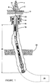
- Figure 1 is a semi-submersible drilling platform showing the drilling rig with casing and the target reservoir.
- Figure 2 shows a bottom hole assembly including drilling means and completion means in the casing.
- Figure 3 shows the embodiment of Fig. 2 in the process of drilling a bore hole.
- Figure 4 shows the embodiment of Fig. 2 with the completion means adjacent the target reservoir.
- Figure 5 shows one embodiment of the present invention used for placing a gravel slurry adjacent the target reservoir.
- Figure 6 shows a second embodiment of the present invention used for placing a gravel slurry adjacent the target reservoir.
- Fig. 1 depicts a semi-submersible drilling vessel 2 that has contained thereon a drilling rig 4 .
- a sub-sea Blow-Out Preventor stack 8 is positioned on the ocean floor 10 , with a riser 12 linking the sub-sea BOP stack 8 and the surface BOPs 6. Extending into the earth from the sub-sea stack 8 will be the well casings, including the conductor, surface, and intermediate 14, 16, and 18 , respectfully.
- the casing strings will intersect various subterranean reservoirs 22 , some of which may contain hydrocarbons. As is shown in Fig. 1, a target reservoir 24 has yet to be drilled through. A work string 20 is positioned within the riser 12 and casing string 18. The string 20 has attached thereto a bottom hole assembly 26 containing a drilling means and sand control means, all of which will be discussed in detail hereafter. It should be noted that throughout the description of the preferred embodiments, like numbers used in the various figures refer to like components.
- the bottom hole assembly 26 will be attached to a work string 202 .
- the work string 202 will contain a packer means 204 for sealingly engaging the casing string 206 so that an upper annulus 208 and lower annulus 210 is formed.
- the work string 202 may contain subsurface safety valve, and any other necessary nipple setting profiles 214 .
- the bottom hole assembly 200 will consist of bit means 218 for drilling a bore hole, with the bit means 218 depicted being a tricone rotating bit; however, it should be understood that other types of bit means, such as PDC bits may be employed.
- the assembly 26 will further consist of a motor means 220 for effecting rotation to the bit means 218, which in Fig. 2 is a stator 222 and rotor 224 assembly well known in the art.
- the motor means 220 will in turn be connected to the deflection means 226 for causing a deflection in the bottom hole assembly so that the trajectory of the drilling path is curved. While a deflection means 226 has been shown, the teachings of this invention are certainly applicable to vertical hole completions.
- the deflection means 226 may be of the type where the angle of deflection is manipulated at the surface and run into the well bore, or alternatively, the deflection means 226, and in particularly the angle of deflection, is automatically controllable by transmitting a signal down hole by means of mud pulse, or acoustic telemetry. Alternately, the deflection means 226 may be controlled by a predetermined pressure force exerted on the deflection means 226 through either the inner diameter or outer diameter of deflection means 226.
- the non-rotating swivel means (not shown) which is commercially available from Baker Hughes Incorporated and sold under the product name Model "A" Swivel performs the function of preventing relative rotation of the work string with respect to the threadedly engaging packer, thus assuring that the left hand packer threads of any production packers disposed on the production string cannot be disengaged during the necessary right hand rotation of the work string required to set or unset components of the bottom hole assembly during the drilling and placement of the sand control screen.
- the deflection means 226 will be attached to the means for preventing sand production 228 , which in the embodiment shown is a sand control screen means in that there is a segment of perforated pipe 230 that has disposed about it a wire mesh screen 232 .
- a soluble means, disposed about the sand control means 228, may be added for preventing the contamination of the sand control means from the drilling fluids and cuttings encountered during the drilling, placement, and completion of the well.
- the soluble means can also serve the purpose of forming an impermeable barrier thereby allowing the circulation of the drilling fluid down the inner diameter of the workstring 202, out the bit means 218 and up the outer diameter of the workstring 202.
- the soluble means may be removed by acid treatments.
- the soluble means may be a wax composition; however, other types of compounds are available. The actual soluble means employed will depend on down hole temperature, and wellbore fluid composition.
- the inner diameter of the sand preventing means 228, as well as the inner diameter of the remainder of the bottom hole assembly is denoted as 233 .
- the detaching means 234a for detaching the preventing means 228 from the deflection means 226 and the remainder of the bottom hole assembly 200 is a releasable mechanism means that has contained thereon engaging collet members 236a that is well known in the art such as those devices used to release tubing conveyed perforating guns.
- the detaching means 234 is commercially available in the form of Mechanical and Hydraulic Release Subs from Baker Hughes Incorporated.
- a second detaching means 234b for detaching the work string 202 from the bottom hole assembly 200 is also shown, which has contained thereon engaging collet members 236b .
- the bottom hole assembly 26 is depicted wherein the bottom hole assembly 26 is in the process of drilling to a target reservoir 242.
- the work string 202 is a production tubing string even though other types of conduits could be used such as coiled tubing.
- a drilling fluid is pumped down the inner diameter 240 of production tubing 202, through the inner diameter 233 of the sand control means, and into the motor means 220 thereby effecting rotation of the bit means 218.
- the production tubing 202 is the drilling conduit, and the cuttings and circulation of the drilling fluids follow the path of the annulus 208, 210 in the open hole section as well as the cased hole section.
- an orienting means operably associated with the motor, for determining the direction and location of the bit means and generating a signal in response thereto.
- logging means for evaluating the lithology of a subterranean reservoir and generating a signal in response thereto, and non-rotating means, operably connected on one end to the drill string and on the second end to said motor, for imparting selective rotation to the bit means may also be included.
- the procedure first comprises pumping a drilling fluid down the work string 202 thereby effecting rotation of the drilling means 218; next, orienting means and logging means will generate a representative signal, and that signal will be transmitted to the surface.
- the path of the bit means 218 may then be plotted in order to determine the location of the bit. The driller can then steer the bit means in response to the bit location, and ultimately drill through a target reservoir 242 with use of the bit means 218.
- Fig. 4 depicts a bore hole that has been drilled such that the target reservoir 242 has been encountered and the bore hole drilled to a sufficient depth so that the sand prevention means 228 is adjacent the target reservoir 242.
- the method and assembly of the present invention also provides for the placement of a gravel pack slurry in the annulus 210 adjacent the target reservoir 242.
- the workstring for this particular embodiment will contain the previously described bottom hole assembly 26 that includes the motor means 220, bit means 218, and the screen means 228.
- bottom hole assembly 200 In order to place a gravel slurry into the annulus 210, it is also necessary that bottom hole assembly 200 also contain a gravel pack extension and crossover tool means 260 well known in the art and commercially available from Baker Hughes Incorporated under the trade name Model "S-2" Cross-Over, and the "S-1" Gravel Pack Extension.
- the gravel pack extension and crossover tool means 260 will contain a sliding sleeve 262 that is slidable from a closed position to an open position, and is generally actuated by dropping a ball (not shown) from the surface, with the ball resting on the sliding sleeve 262. By pressuring up on the internal diameter of the work string, the ball will force the sleeve to an open position.
- the entire bottom hole assembly 26 is connected to a packer means 266 that will sealingly engage the casing string 206 so that an upper annulus 208 and a lower annulus 210 are formed.
- the packer means 266 will have operatively connected thereto a setting tool 267 , with the associated wash pipe 268 extending therefrom, with the entire assembly being well known in the art and commercially available from Baker Hughes Incorporated under the trade name "SC" Setting Tool, or alternatively, the "BDP" Setting Tool may be used.
- wash pipe 268 serves as a conduit for the drilling fluid during the drilling phase.
- the path of the fluid during drilling is through the inner diameter of the work string 202, through the packer means 266, into the inner diameter of the wash pipe 268 and through the motor means 220 when the wash pipe 268 is used, it is not necessary to place the soluble compound about the screen 228.
- the packer is released from the wash pipe and setting tool by rotating the workstring 202 so that the setting tool 267 and wash pipe 268 disengage by the disengagement via the threads at 269 ; thereafter, the setting tool 267 may be picked up which in turn lifts the wash pipe 268 which had been previously stung into the top of the motor means 220.
- the entire wash pipe assembly 268 is lifted up so that the end of the wash pipe 268 is adjacent the screen means 228 (not shown). In this position, the well can be gravel packed.
- the sliding sleeve 262 had been opened, thus, once the wash pipe is in the proper position, the gravel packing process may begin and the sand slurry is pumped down the inner diameter of the work string 202.
- the sand slurry exits into the annulus 210 at ports 264 and 265 into the annulus 210.
- the fluid of the sand slurry will be returned through the porous sand screen 228 and into the bottom of the wash pipe 268, and then up through the inner diameter of the wash pipe 268 and is ultimately crossed-over to the annulus 208.
- the workstring 202, setting tool 267 and wash pipe 268 can be removed from the wellbore.
- the production string is run into the wellbore, with the production string being stung into the top of the packer means 266. Hydrocarbons from the reservoir 242 may now be produced through the sand screen 228 and up the inner diameter of the production string.
- FIG. 6 an alternate embodiment of the present invention is depicted that can be used when gravel packing is desirable.
- the bottom hole assembly 26 including the screen 228, motor means 220 and bit means 218 is essentially the same as those depicted in Figs. 2, 3, and 4.
- the packer means 274 is commercially available from Baker Hughes Incorporated under the name Retrievable Hydraulic Set Packer. Extending downward from the production packer 274 will be the over shot means 276 for landing the packer means 274.
- the remainder of the bottom hole assembly 200 is identical to the bottom hole assembly 26 described in Figs. 2, 3, and 4.
- the procedure for drilling, completing and gravel packing the hydrocarbon reservoir 242 utilizing the embodiment of Fig. 6 would include drilling through the target reservoir 242 as previously described with the bottom hole assembly depicted in Fig. 3.
- the annulus 210 can be gravel packed by circulating a gravel pack slurry down the annulus 208 and getting the fluid returns through the screen means 228.
- the reason for not placing the packer means 274 on the original bottom hole assembly is that the outer diameter of the packer means 274 is too large, and therefore, the gravel slurry could not be effectively placed down hole without the slurry bridging about the packer 274.
- the work string is detached from the remainder of the bottom hole assembly 26 utilizing the detaching means 234b that is positioned above the screen means 228 as previously described in Fig. 3.
- the detaching means 234b has contained thereon engaging collet members 236b that is well known in the art such as those devices used to release tubing conveyed perforating guns.
- the detaching means 234b also contains a nipple profile.
- the detaching means 234B is commercially available in the form of Mechanical and Hydraulic Release Subs from Baker Hughes Incorporated.
- the detaching means 234 is not shown in Fig. 6 since the assembly shown is after the detachment and removal of the workstring from the wellbore and the packer means 274 has been subsequently lowered into the wellbore on the production string.
- the outer diameter nipple profile 277 with the rest of the bottom hole assembly 26 remains within the wellbore.
- a production tubing string is run back into the wellbore, with the production tubing string having the previously mentioned packer means 274 and the over shot means 276 extending therefrom.
- the over shot 276 will be stung into and attach with the previously mentioned outer diameter nipple profile 277.
- the packer means 274 is set against the casing string by hydraulic means such as pressuring up on the annulus. After the packer is set and an upper annulus 208 and lower annulus 210 is formed, the well may then be placed on production.
Landscapes
- Engineering & Computer Science (AREA)
- Mining & Mineral Resources (AREA)
- Geology (AREA)
- Life Sciences & Earth Sciences (AREA)
- Fluid Mechanics (AREA)
- Environmental & Geological Engineering (AREA)
- Physics & Mathematics (AREA)
- General Life Sciences & Earth Sciences (AREA)
- Geochemistry & Mineralogy (AREA)
- Chemical & Material Sciences (AREA)
- Analytical Chemistry (AREA)
- Mechanical Engineering (AREA)
- Earth Drilling (AREA)
- Drilling And Boring (AREA)
- Auxiliary Devices For Machine Tools (AREA)
Applications Claiming Priority (2)
| Application Number | Priority Date | Filing Date | Title |
|---|---|---|---|
| US08/343,814 US5842528A (en) | 1994-11-22 | 1994-11-22 | Method of drilling and completing wells |
| US343814 | 1994-11-22 |
Publications (2)
| Publication Number | Publication Date |
|---|---|
| EP0713951A2 true EP0713951A2 (de) | 1996-05-29 |
| EP0713951A3 EP0713951A3 (de) | 1998-01-28 |
Family
ID=23347787
Family Applications (1)
| Application Number | Title | Priority Date | Filing Date |
|---|---|---|---|
| EP95118242A Withdrawn EP0713951A3 (de) | 1994-11-22 | 1995-11-20 | Verfahren zum Bohren und Komplettieren von Bohrlöchern |
Country Status (3)
| Country | Link |
|---|---|
| US (1) | US5842528A (de) |
| EP (1) | EP0713951A3 (de) |
| NO (1) | NO954689L (de) |
Cited By (6)
| Publication number | Priority date | Publication date | Assignee | Title |
|---|---|---|---|---|
| WO1999007975A1 (en) * | 1997-08-08 | 1999-02-18 | Baker Hughes Incorporated | Method and apparatus for drilling and completing wells |
| WO2006010906A1 (en) * | 2004-07-24 | 2006-02-02 | Bamford Anthony S | Improvements in or relating to subsea drilling |
| WO2009066097A1 (en) * | 2007-11-23 | 2009-05-28 | Sam Simonian | Completion arrangement |
| CN101936134A (zh) * | 2009-01-22 | 2011-01-05 | 普拉德研究及开发股份有限公司 | 当钻井时选择最优井眼轨迹 |
| US8590634B2 (en) | 2004-07-24 | 2013-11-26 | Geoprober Drilling Limited | Subsea drilling |
| US9574406B2 (en) | 2009-10-20 | 2017-02-21 | Deep Casing Tools, Ltd. | Wellbore completion system with reaming tool |
Families Citing this family (18)
| Publication number | Priority date | Publication date | Assignee | Title |
|---|---|---|---|---|
| US6070665A (en) * | 1996-05-02 | 2000-06-06 | Weatherford/Lamb, Inc. | Wellbore milling |
| US6202752B1 (en) | 1993-09-10 | 2001-03-20 | Weatherford/Lamb, Inc. | Wellbore milling methods |
| US6547006B1 (en) | 1996-05-02 | 2003-04-15 | Weatherford/Lamb, Inc. | Wellbore liner system |
| US6089319A (en) * | 1998-03-23 | 2000-07-18 | Weatherford/Lamb, Inc. | Whipstock |
| US6202742B1 (en) * | 1998-11-03 | 2001-03-20 | Halliburton Energy Services, Inc. | Pack-off device for use in a wellbore having a packer assembly located therein |
| US6364017B1 (en) | 1999-02-23 | 2002-04-02 | Bj Services Company | Single trip perforate and gravel pack system |
| US6374918B2 (en) | 1999-05-14 | 2002-04-23 | Weatherford/Lamb, Inc. | In-tubing wellbore sidetracking operations |
| US6343650B1 (en) * | 1999-10-26 | 2002-02-05 | Halliburton Energy Services, Inc. | Test, drill and pull system and method of testing and drilling a well |
| US6390195B1 (en) | 2000-07-28 | 2002-05-21 | Halliburton Energy Service,S Inc. | Methods and compositions for forming permeable cement sand screens in well bores |
| US6672390B2 (en) * | 2001-06-15 | 2004-01-06 | Shell Oil Company | Systems and methods for constructing subsea production wells |
| US7373978B2 (en) * | 2003-02-26 | 2008-05-20 | Exxonmobil Upstream Research Company | Method for drilling and completing wells |
| US7401648B2 (en) * | 2004-06-14 | 2008-07-22 | Baker Hughes Incorporated | One trip well apparatus with sand control |
| US20070193778A1 (en) * | 2006-02-21 | 2007-08-23 | Blade Energy Partners | Methods and apparatus for drilling open hole |
| US7661476B2 (en) | 2006-11-15 | 2010-02-16 | Exxonmobil Upstream Research Company | Gravel packing methods |
| US10036234B2 (en) * | 2012-06-08 | 2018-07-31 | Schlumberger Technology Corporation | Lateral wellbore completion apparatus and method |
| US10590723B2 (en) * | 2017-06-28 | 2020-03-17 | Baker Hughes, A Ge Company, Llc | Method for removing a downhole plug |
| US10753178B2 (en) * | 2017-06-28 | 2020-08-25 | Baker Hughes, A Ge Company, Llc | Method for removing a downhole plug |
| EP4577726A1 (de) * | 2022-08-26 | 2025-07-02 | ConocoPhillips Company | System und verfahren zum umdrehen eines bohrlochs zur herstellung |
Family Cites Families (27)
| Publication number | Priority date | Publication date | Assignee | Title |
|---|---|---|---|---|
| US1279783A (en) * | 1918-03-05 | 1918-09-24 | Robert Stirling | Method and apparatus for controlling and pumping oil-wells. |
| US1974667A (en) * | 1933-01-05 | 1934-09-25 | Eagle Pencil Co | Combined bookmark and lead pencil |
| US2229493A (en) * | 1940-01-11 | 1941-01-21 | Stanolind Oil & Gas Co | Method and apparatus for completing wells |
| US2726847A (en) * | 1952-03-31 | 1955-12-13 | Oilwell Drain Hole Drilling Co | Drain hole drilling equipment |
| US2778603A (en) * | 1953-06-22 | 1957-01-22 | Oilwell Drain Hole Drilling Co | Preparation of well drain holes for production |
| US3463228A (en) * | 1967-12-29 | 1969-08-26 | Halliburton Co | Torque resistant coupling for well tool |
| US3880233A (en) * | 1974-07-03 | 1975-04-29 | Exxon Production Research Co | Well screen |
| US4202411A (en) * | 1978-05-24 | 1980-05-13 | Baker International Corporation | Acid soluble coating for well screens |
| US4445578A (en) * | 1979-02-28 | 1984-05-01 | Standard Oil Company (Indiana) | System for measuring downhole drilling forces |
| US4239084A (en) * | 1979-07-11 | 1980-12-16 | Baker International Corporation | Acid soluble coating for well screens |
| US4270619A (en) * | 1979-10-03 | 1981-06-02 | Base Jimmy D | Downhole stabilizing tool with actuator assembly and method for using same |
| US4335788A (en) * | 1980-01-24 | 1982-06-22 | Halliburton Company | Acid dissolvable cements and methods of using the same |
| US4544041A (en) * | 1983-10-25 | 1985-10-01 | Rinaldi Roger E | Well casing inserting and well bore drilling method and means |
| US4651837A (en) * | 1984-05-31 | 1987-03-24 | Mayfield Walter G | Downhole retrievable drill bit |
| US4828053A (en) * | 1988-01-12 | 1989-05-09 | Maurer Engineering, Inc. | Deviated wellbore drilling system and apparatus |
| US4962818A (en) * | 1989-07-17 | 1990-10-16 | Smith International, Inc. | Downhole motor with an enlarged connecting rod housing |
| US5148875A (en) * | 1990-06-21 | 1992-09-22 | Baker Hughes Incorporated | Method and apparatus for horizontal drilling |
| CA2024061C (en) * | 1990-08-27 | 2001-10-02 | Laurier Emile Comeau | System for drilling deviated boreholes |
| US5197553A (en) * | 1991-08-14 | 1993-03-30 | Atlantic Richfield Company | Drilling with casing and retrievable drill bit |
| US5234055A (en) * | 1991-10-10 | 1993-08-10 | Atlantic Richfield Company | Wellbore pressure differential control for gravel pack screen |
| US5255741A (en) * | 1991-12-11 | 1993-10-26 | Mobil Oil Corporation | Process and apparatus for completing a well in an unconsolidated formation |
| US5253708A (en) * | 1991-12-11 | 1993-10-19 | Mobil Oil Corporation | Process and apparatus for performing gravel-packed liner completions in unconsolidated formations |
| NO306522B1 (no) * | 1992-01-21 | 1999-11-15 | Anadrill Int Sa | Fremgangsmaate for akustisk overföring av maalesignaler ved maaling under boring |
| GB9210846D0 (en) * | 1992-05-21 | 1992-07-08 | Baroid Technology Inc | Drill bit steering |
| US5311952A (en) * | 1992-05-22 | 1994-05-17 | Schlumberger Technology Corporation | Apparatus and method for directional drilling with downhole motor on coiled tubing |
| US5320178A (en) * | 1992-12-08 | 1994-06-14 | Atlantic Richfield Company | Sand control screen and installation method for wells |
| US5368109A (en) * | 1993-11-04 | 1994-11-29 | Slim Dril International Inc. | Apparatus for arcuate drilling |
-
1994
- 1994-11-22 US US08/343,814 patent/US5842528A/en not_active Expired - Fee Related
-
1995
- 1995-11-20 EP EP95118242A patent/EP0713951A3/de not_active Withdrawn
- 1995-11-20 NO NO954689A patent/NO954689L/no not_active Application Discontinuation
Non-Patent Citations (1)
| Title |
|---|
| None |
Cited By (9)
| Publication number | Priority date | Publication date | Assignee | Title |
|---|---|---|---|---|
| WO1999007975A1 (en) * | 1997-08-08 | 1999-02-18 | Baker Hughes Incorporated | Method and apparatus for drilling and completing wells |
| GB2333789A (en) * | 1997-08-08 | 1999-08-04 | Baker Hughes Inc | Method and apparatus for drilling and completing wells |
| WO2006010906A1 (en) * | 2004-07-24 | 2006-02-02 | Bamford Anthony S | Improvements in or relating to subsea drilling |
| US7819204B2 (en) | 2004-07-24 | 2010-10-26 | Geoprober Drilling Limited | Subsea drilling |
| US8590634B2 (en) | 2004-07-24 | 2013-11-26 | Geoprober Drilling Limited | Subsea drilling |
| WO2009066097A1 (en) * | 2007-11-23 | 2009-05-28 | Sam Simonian | Completion arrangement |
| CN101936134A (zh) * | 2009-01-22 | 2011-01-05 | 普拉德研究及开发股份有限公司 | 当钻井时选择最优井眼轨迹 |
| CN101936134B (zh) * | 2009-01-22 | 2015-04-01 | 普拉德研究及开发股份有限公司 | 当钻井时选择最优井眼轨迹 |
| US9574406B2 (en) | 2009-10-20 | 2017-02-21 | Deep Casing Tools, Ltd. | Wellbore completion system with reaming tool |
Also Published As
| Publication number | Publication date |
|---|---|
| NO954689L (no) | 1996-05-23 |
| US5842528A (en) | 1998-12-01 |
| NO954689D0 (no) | 1995-11-20 |
| EP0713951A3 (de) | 1998-01-28 |
Similar Documents
| Publication | Publication Date | Title |
|---|---|---|
| US5662170A (en) | Method of drilling and completing wells | |
| US5842528A (en) | Method of drilling and completing wells | |
| US5667023A (en) | Method and apparatus for drilling and completing wells | |
| EP2456947B1 (de) | Offshore-bohrsystem | |
| EP2287439B1 (de) | Verfahren zum Abschließen eines Bohrlochs | |
| EP0840834B1 (de) | Vorrichtung und verfahren zum bohren und kompletieren mehrerer bohrungen | |
| AU752847B2 (en) | Method and apparatus for drilling a borehole into a subsea abnormal pore pressure environment | |
| US3602303A (en) | Subsea wellhead completion systems | |
| US7637316B2 (en) | Wellbore system | |
| NO349187B1 (en) | Reverse circulation debris removal tool for setting isolation seal assembly | |
| CN112313392B (zh) | 井建造和完井方法 | |
| Juiniti et al. | Campos Basin: Lessons learned and critical issues to be overcome in drilling and completion operations | |
| US11873626B2 (en) | Large diameter water well control | |
| AU4058597A (en) | Method and apparatus for drilling and completing wells | |
| Koroknay | New development techniques in Bass Strait |
Legal Events
| Date | Code | Title | Description |
|---|---|---|---|
| PUAI | Public reference made under article 153(3) epc to a published international application that has entered the european phase |
Free format text: ORIGINAL CODE: 0009012 |
|
| AK | Designated contracting states |
Kind code of ref document: A2 Designated state(s): DE FR GB NL |
|
| PUAL | Search report despatched |
Free format text: ORIGINAL CODE: 0009013 |
|
| AK | Designated contracting states |
Kind code of ref document: A3 Designated state(s): DE FR GB NL |
|
| 17P | Request for examination filed |
Effective date: 19980722 |
|
| 17Q | First examination report despatched |
Effective date: 20000303 |
|
| STAA | Information on the status of an ep patent application or granted ep patent |
Free format text: STATUS: THE APPLICATION HAS BEEN WITHDRAWN |
|
| 18W | Application withdrawn |
Withdrawal date: 20001102 |