EP0713116A1 - Anamorphotic system and thermal imager equippes with such a system - Google Patents
Anamorphotic system and thermal imager equippes with such a system Download PDFInfo
- Publication number
- EP0713116A1 EP0713116A1 EP95402542A EP95402542A EP0713116A1 EP 0713116 A1 EP0713116 A1 EP 0713116A1 EP 95402542 A EP95402542 A EP 95402542A EP 95402542 A EP95402542 A EP 95402542A EP 0713116 A1 EP0713116 A1 EP 0713116A1
- Authority
- EP
- European Patent Office
- Prior art keywords
- plane
- optical
- prism
- ratio
- anamorphosis
- Prior art date
- Legal status (The legal status is an assumption and is not a legal conclusion. Google has not performed a legal analysis and makes no representation as to the accuracy of the status listed.)
- Withdrawn
Links
- 230000004075 alteration Effects 0.000 claims abstract description 8
- 230000003287 optical effect Effects 0.000 claims description 66
- 210000001747 pupil Anatomy 0.000 claims description 27
- 239000000463 material Substances 0.000 claims description 16
- 238000001514 detection method Methods 0.000 claims description 13
- 230000003595 spectral effect Effects 0.000 claims description 12
- 238000003331 infrared imaging Methods 0.000 claims description 10
- 230000001179 pupillary effect Effects 0.000 claims description 10
- 230000021615 conjugation Effects 0.000 claims description 7
- 238000003384 imaging method Methods 0.000 claims description 7
- 210000003128 head Anatomy 0.000 claims description 5
- 230000015572 biosynthetic process Effects 0.000 claims description 4
- 239000000470 constituent Substances 0.000 claims description 2
- 230000001902 propagating effect Effects 0.000 claims description 2
- 238000011084 recovery Methods 0.000 claims 1
- 230000035945 sensitivity Effects 0.000 claims 1
- 230000007547 defect Effects 0.000 description 6
- XUIMIQQOPSSXEZ-UHFFFAOYSA-N Silicon Chemical compound [Si] XUIMIQQOPSSXEZ-UHFFFAOYSA-N 0.000 description 5
- 201000009310 astigmatism Diseases 0.000 description 5
- 229910052710 silicon Inorganic materials 0.000 description 5
- 239000010703 silicon Substances 0.000 description 5
- 230000006978 adaptation Effects 0.000 description 4
- 230000005540 biological transmission Effects 0.000 description 4
- 230000004907 flux Effects 0.000 description 4
- 230000014509 gene expression Effects 0.000 description 4
- 229910052732 germanium Inorganic materials 0.000 description 3
- GNPVGFCGXDBREM-UHFFFAOYSA-N germanium atom Chemical compound [Ge] GNPVGFCGXDBREM-UHFFFAOYSA-N 0.000 description 3
- 230000010354 integration Effects 0.000 description 3
- 238000012545 processing Methods 0.000 description 3
- 230000002745 absorbent Effects 0.000 description 2
- 239000002250 absorbent Substances 0.000 description 2
- 239000003990 capacitor Substances 0.000 description 2
- 230000003111 delayed effect Effects 0.000 description 2
- 230000000694 effects Effects 0.000 description 2
- 210000000887 face Anatomy 0.000 description 2
- 230000001681 protective effect Effects 0.000 description 2
- 238000004611 spectroscopical analysis Methods 0.000 description 2
- 238000013519 translation Methods 0.000 description 2
- 230000009471 action Effects 0.000 description 1
- 239000002131 composite material Substances 0.000 description 1
- 239000004020 conductor Substances 0.000 description 1
- 238000007796 conventional method Methods 0.000 description 1
- 238000001816 cooling Methods 0.000 description 1
- 230000000593 degrading effect Effects 0.000 description 1
- 238000000151 deposition Methods 0.000 description 1
- 238000013461 design Methods 0.000 description 1
- 238000011161 development Methods 0.000 description 1
- 238000010586 diagram Methods 0.000 description 1
- 238000006073 displacement reaction Methods 0.000 description 1
- 235000021183 entrée Nutrition 0.000 description 1
- WPYVAWXEWQSOGY-UHFFFAOYSA-N indium antimonide Chemical compound [Sb]#[In] WPYVAWXEWQSOGY-UHFFFAOYSA-N 0.000 description 1
- 238000000034 method Methods 0.000 description 1
- 230000003071 parasitic effect Effects 0.000 description 1
- 230000010287 polarization Effects 0.000 description 1
- 230000008569 process Effects 0.000 description 1
- 230000005855 radiation Effects 0.000 description 1
- 230000009467 reduction Effects 0.000 description 1
- 238000005070 sampling Methods 0.000 description 1
Images


Classifications
-
- G—PHYSICS
- G02—OPTICS
- G02B—OPTICAL ELEMENTS, SYSTEMS OR APPARATUS
- G02B25/00—Eyepieces; Magnifying glasses
- G02B25/001—Eyepieces
-
- G—PHYSICS
- G02—OPTICS
- G02B—OPTICAL ELEMENTS, SYSTEMS OR APPARATUS
- G02B13/00—Optical objectives specially designed for the purposes specified below
- G02B13/08—Anamorphotic objectives
- G02B13/10—Anamorphotic objectives involving prisms
-
- G—PHYSICS
- G02—OPTICS
- G02B—OPTICAL ELEMENTS, SYSTEMS OR APPARATUS
- G02B13/00—Optical objectives specially designed for the purposes specified below
- G02B13/14—Optical objectives specially designed for the purposes specified below for use with infrared or ultraviolet radiation
Definitions
- the invention relates to the field of imaging, in particular infrared imaging in which the useful spectral bands are those which promote atmospheric transmission.
- the bands 3 to 5 ⁇ m and 8 to 12 ⁇ m are used, for which there are photosensitive materials well suited for their detection, for example indium antimony (lnSb) or a mercury-cadmium-tellium composite material. (Hg-Cd-Te).
- the invention applies in particular, but not exclusively, to infrared imaging devices with unidirectional, horizontal or vertical scanning, comprising a scene scanning mirror defining an axis of sight for a detector bar of main axis orthogonal to the scanning direction.
- Infrared imaging detectors are in the form of a mosaic of spaced elementary cells, made of photosensitive material and arranged to form a strip.
- TDI type technology initials of the Anglo-Saxon expression “Time and Delay Integration” which means Temporarily Delayed Integration
- Congestion reasons can then lead to using a large spacing between the cells in the direction of the processing circuits, greater than what is desired for optical reasons.
- TDI technology uses a detector mosaic composed of a large number of rows of a few cells arranged in the scanning direction to form a detector strip extending in an orthogonal direction.
- the rows can be aligned, staggered or in an architecture combining these two modes.
- Each cell of the same row then successively receives, during scanning, the same light flux coming from the same portion of the scene.
- the output signals of the cells of the same row are delayed in synchronism with the scanning speed to be accumulated in a summing circuit.
- TDI technology is performed more precisely using charge storage capacitors built into the back of the detector plane.
- the conductors connecting the cells to the capacitors occupy a non-negligible space between the cells.
- a solution is to make cells of rectangular shape whose length and width extend in two main directions, respectively the scanning direction and a direction orthogonal thereto. Under these conditions, the elementary field of view of each of these cells has an elementary field of view ⁇ different according to the two main orthogonal directions.
- This problem has been solved in the field of visible radiation, in particular by Brewster, by developing anamorphic means, for example prisms or cylindrical lenses, to modify the fields contained in a meridian anamorphic plane, without modifying the image in the orthogonal plane. It is possible to quantify the spread obtained by the value of a so-called anamorphosis ratio, equal to the magnification ratio of the anamorphic element in the two main directions.
- the invention aims to overcome these defects by using an anamorphic eyepiece without dioptric aberration, without mechanical complication, while retaining good optical transmission.
- the invention proposes an anamorphic eyepiece with two prisms whose functions are rigorously decoupled: the first prism is dedicated entirely to anamorphosis, and the second prism, used at the minimum of deviation in order to induce no effect anamorphic, is calculated so as to compensate for the dioptric defects induced by the first prism, the two prisms having the same refractive index and being used in parallel beams.
- the subject of the invention is an anamorphic eyepiece comprising a first and a second prism made of a material of known index, arranged head to tail along the same plane of main section, characterized in that, the first and the second prisms being successively crossed by a parallel light beam radiating in a given spectral band and propagating along an axis located in the plane of main section, only the first prism causes an anamorphosis of the beam in a predetermined ratio and has an angle at the apex of which the value is adjusted as a function of that of the desired anamorphosis ratio and of the index of the constituent material in the given spectral band, in that the second prism is oriented relative to the beam emerging from the first prism to be used at its minimum deviation so as not to introduce any anamorphosis, and in that the second prism has an angle at the apex whose value e st adjusted according to those of the anamorphosis ratio and the index to obtain a compensation of axi
- the invention also relates to an infrared imaging device comprising in particular a scanning mirror and an optical transport combination, for forming over time a scene image on an infrared detector mosaic arranged in a cryostat.
- the anamorphic eyepiece is coupled to the optical transport combination to be integrated into the infrared imaging device.
- the transport suit then includes a cylindrical lens in order to obtain a single exit pupil for the entire optical system composed of the eyepiece and the transport suit.
- the transport combination is calculated so that this exit pupil coincides with the actual opening of the cryostat defining the diaphragm, called the cold diaphragm, of the detector.
- this opening is conventionally shaped so that the cold diaphragm allows only the useful flow coming from the scene to pass, by stopping all the parasitic flows emitted by elements of internal structure. Under these conditions, the detector not only receives only the useful flow, but then receives all the useful flow.
- the transport combination advantageously consists of two groups of lenses of positive power, which gives a real and accessible intermediate image, calculated to bring the entrance pupil of the optical system to the axis of rotation of the scanning mirror of the device.
- infrared imagery for fields located in a plane perpendicular to the anamorphic plane.
- a cylindrical lens placed in the vicinity of the intermediate image makes it possible to adjust the pupillary conjugations to keep the entrance pupil always on the scanning mirror.
- the use of a cylindrical lens which acts as a field group finally makes it possible to have a single pupil at the input, whatever the orientations of the fields, located on the scanning mirror. This makes it possible to reduce the dimensions of the scanning mirror and to precisely couple the optical system to a frontal afocal group conventionally arranged at the input of the imaging devices.
- the cylindrical lens does not participate, under the conditions of implementation mentioned, in the power of the optical system.
- the thermal defocusing of this system can then be corrected by moving a single group of lenses.
- the associated mechanics for achieving such a translation is simplified.
- optical system of such an infrared imaging device forms on the detector mosaic an undegraded image due to the fact that the optical transmission is effected by a minimum of elements and the absence of drifts of aiming axes coinciding with the optical axis of this system.
- FIG. 1 A schematic example of anamorphic eyepiece according to the invention is illustrated in FIG. 1 in section on a plane of main section of the prisms shown.
- the anamorphic eyepiece has two prisms with main sections merged with the plane of the figure and arranged head to tail, a first prism P1 with an angle at the apex A1 and main faces f e and f s , and a second prism P2 d ' angle at the vertex A2 and main faces f ' e and f' s .
- the two prisms, formed from the same material have the same refractive index n.
- An incident parallel light beam F i strikes the entry face f e of the first prism P1 and emerges from the exit face f s of this prism in the form of a parallel beam F i .
- the beam F i forms an angle i1 with the exit normal N1 perpendicular to the face f s .
- the incident beam F i is shown perpendicular to the input face f e .
- the beam F i emerging from the prism P1 strikes the input face f ' e of the second prism P2 at an angle i2, measured with respect to the normal N2 at the input face, then emerges from this prism P2 by the face of exit f ' s . at an angle i'2, measured with respect to the normal N'2 at the face f ' s .
- the first prism is anamorphic.
- the anamorphosis is created in the main section plane by the anisotropic deflection operated by the prism on the incident beam.
- the section of the beam is no longer circular but is narrowed in the plane of main section, which results in the figure by a narrowing of the beam F i after crossing the prism.
- the emerging beam when the beam F i scans an observation field, the emerging beam describes a wider field in the plane of main section due to the principle of the conservation of the quantity of light flux transported. According to this principle, the product "swept field” ⁇ "section of pupil crossed” is constant for a given incident beam.
- the anamorphosis can be defined, for the same field scanned in the plane of main section and in an orthogonal plane as the ratio m between the magnifications used in these two planes.
- the second prism P2 is on the other hand oriented relative to the emerging beam of the first prism P1 so as to be used at its minimum deflection. Under these conditions, the angles of incidence and emergence of the beam F i are identical in the plane of main section for which the angle of incidence i2 is therefore equal to the angle of emergence i'2. Thus, the prism P2 does not introduce any additional anamorphosis.
- the prism P2 is adjusted to compensate for all of the dioptric aberrations introduced into the first prism P1.
- Dioptric aberrations can be translated, directly or by parametric equivalence as explained below, by a variation of index. If the angle of the second prism, A2, is adjusted appropriately, the prisms, used under the same conditions - same material, same spectral band, same main section - cause identical diotic aberrations, which results in the same variation d 'index.
- the variation in index ⁇ n is caused by dioptric defects which originate from the chromaticism, the axial drift in temperature, and the distortion which causes a curvature of the lines perpendicular to the plane of main section.
- FIG. 2 represents in a side view a prism P of angle at the apex A defined in a plane of main section of the prism.
- a portion of line L, formed in a plane ⁇ perpendicular to the plane of main section of the prism for polarization optics (not shown), has an image in the plane ⁇ formed by passing through the prism P which has a certain curvature.
- An incident ray R i coming from a point of the line L and which forms an angle ⁇ with the normal N of the plane of principal section in the plane ⁇ , has for image a ray emerging R ' i through the prism P.
- an anamorphic eyepiece consists of two silicon prisms with an index equal to 3.4254 at the average wavelength of the spectral band 3-5 ⁇ m; this eyepiece performs an anamorphosis with a ratio m equal to 2 when the apex angles A1 and A2 of the first and second prism are respectively 14.807 ° and 22.600 °, and when the incident beam, taken perpendicular to the entry face of the first prism, comes out of this prism and enters the second prism (used at its minimum deviation) at angles i1 and i2 respectively equal to 61.093 ° and 42.160 °.
- the calculation shows that its variations, caused for example by a temperature difference ⁇ 40 ° C or along a horizontal observation field of ⁇ 1.25 ° in the plane of main section, does not exceed 0.3%, which again remains negligible.
- An anamorphic device such as that which has just been described can be integrated into an infrared imaging device, for example an observation camera in the infrared spectral band 3-5 ⁇ m.
- the anamorphic eyepiece is coupled to an optical transport combination which forms a final image on a detector mosaic and which is adapted to the eyepiece to present a single exit pupil in a predetermined plane.
- the exit pupil is then positioned in the same plane.
- Figure 3 shows schematically a sectional view of an infrared imaging device according to the invention.
- This exemplary embodiment is that of an infrared camera with horizontal scanning.
- Figure 3 illustrates, in horizontal section, the main elements related to the invention.
- a frontal afocal group 10 which makes it possible to properly adapt the fields scanned by the camera to operational needs , an oscillating scanning mirror 20 of vertical axis V'V perpendicular to the plane of the figure which ensures the horizontal exploration of the image of a scene observed by the camera in a given field of view, an anamorphic eyepiece 30 coupled to a combination of image transport 40 to form the optical system of the camera, and a cryostat 50.
- This cryostat defines a diaphragm 51, hereinafter called the cold screen, and houses a detection mosaic 52 forming a strip oriented in a direction direction perpendicular to the scanning direction; the mosaic is associated with an electronic processing circuit signal (not shown).
- the mosaic is cooled by a cold finger 53 maintained at about 77 ° K by a cooling machine (not shown).
- the optical transport combination 40 is intended to transport the image of the instantaneous scene portion formed by the horizontal scanning mirror 20 to the detector mosaic 52.
- This combination can, on the other hand, be calculated so as to define an entrance pupil for the incident flow treatment unit 20-50, which substantially coincides with the axis of rotation V'V of the mirror 20. Under these conditions, the dimensions of this mirror can be reduced to minimum values and are therefore optimized. Such an optical combination calculation does not raise any particular problem.
- the frontal afocal group 10 then operates directly for the instantaneous opening of the optical processing assembly: no pupil shift induced by the scanning occurs.
- the anamorphic eyepiece 30 is of the type described above. It consists of the two prisms P1 and P2, arranged head to tail along the same plane of main section coinciding with the horizontal plane.
- Such an anamorphic, achromatic device corrected for thermal drifts and practically devoid of distortions, makes it possible to reduce the elementary field of view of each detection cell in the horizontal plane coinciding with the main section plane of the prisms.
- the horizontal field reduction is then caused by the upper value of the focal length of the optical system in the main section plane coinciding with the horizontal scanning plane.
- the vertical and horizontal elementary fields are similar if the anamorphosis ratio is chosen equal to the dimensional ratio between the width and the height of the cells.
- the optical transport combination comprises a cylindrical field lens 41 to compensate for pupillary astigmatism at the input of this combination.
- This pupillary astigmatism is caused by the anamorphic device 30 which induces the formation of input pupils offset in the plane of main section and in the orthogonal vertical plane as illustrated below.
- the cylindrical lens 41 has a vertical axis in the example described, and has plano-convex faces calculated so that the optical power in the horizontal plane compensates for the pupillary offset.
- the calculation of the transport combination can be adapted so that the entrance pupil, image of the aperture diaphragm, is on the axis of rotation of the scanning mirror and that it does not depend on position of the field orientation.
- the cold screen 51 constitutes the aperture diaphragm of the camera.
- the entrance pupils are conjugated by the optics composing the eyepiece and the prisms of this aperture diaphragm.
- Such a screen is conventionally adapted so as to let through only the useful beams, by interrupting the spurious signals emitted or returned by the structural elements internal to the camera.
- the detector mosaic receives not only only the useful flux coming from of the observed scene, but also all the useful flow.
- the cold diaphragm can be elliptical in shape, the dimensional relationships between the large and the minor axis being worth the ratio of anamorphosis.
- the lens 41 does not contribute to the optical power produced by the transport combination 40, since it is calculated to cause only a pupil translation in the main section plane of the anamorphic system 30.
- the thermal defocuses of this combination are identical in all the planes, so that the conventional method of compensation by displacement of a single group of lenses of the combination, remains applicable.
- a protective filter of the saturable absorbent type in order to obtain protection against laser threat.
- a filter is all the more effective as the optical density is high.
- the scanning mirror 20 and the anamorphic eyepiece 30 operating in parallel beams a real image can be formed in the optical transport combination.
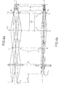
- FIGS. 4a and 4b more precisely represent the optical path of an incident beam coming from an observed scene, after crossing the prismatic anamorphoser, respectively in a vertical field of view equal to 2 ⁇ 10.2 ° according to the plane vertical, and 2 ⁇ 2.54 ° at the input of the optical transport, or 2 ⁇ 1.27 ° at the input of the eyepiece, along the horizontal plane covered by the horizontal scanning mirror.
- FIGS. 4a and 4b show more particularly the pupillary conjugations produced by the combination of optical transport, respectively in the vertical plane coinciding with the vertical field of view, and in the horizontal plane coinciding with the horizontal field of view.
- the optical transport combination is calculated so that the image of the entrance pupil formed on the scanning mirror is projected onto the detector 52, whether in the vertical or horizontal plane.
- the anamorphic eyepiece causes pupillary astigmatism which is shown in FIGS. 4a and 4b by an offset ⁇ between the image of the entrance pupil of the optical system obtained by the anamorphic eyepiece. , called P v in the vertical plane and P h in the horizontal plane.
- the optical combination 40 is composed of two optical groups G1 and G2 which produce a pupillary conjugation between the pupil (not shown) located on the scanning mirror 20, and the exit pupil P s of the optical system. The combination is calculated so that this exit pupil coincides with the opening of the diaphragm of the cold diaphragm 51, whatever the position of the entry pupils P v and P h .
- the cylindrical lens 41 is arranged in the plane of formation of the intermediate image I i and calculated to produce an optical power only in the horizontal field of view in order to make the image of the pupil P h coincide with the cold screen 51 Regarding the vertical field of view, the transport combination is calculated to directly obtain this pupillary conjugation between P v and the pupil of the cold screen 51 without the cylindrical lens 41 producing optical power in this field of view. view.
- the intermediate image I i is formed between the optical groups G1 and G2.
- the optical group G2 can be more precisely formed of two lenses L2 and L3, the lens L2 constituting with the head optical group G1 an afocal group of Kepler type forming a real and accessible intermediate image.
- the lens L3 is a target for resuming final focus on the plane of the detector mosaic 52.
- the optical transport combination has an overall focal distance of 22.6 mm to adapt to the physical dimensions of the 8.1 mm ⁇ 2 mm detection mosaic.
- Each elementary detection cell having, in this embodiment, a dimension equal to 28 ⁇ m ⁇ 40 ⁇ m, the apex angles of the prisms of the eyepiece anamorphic lens can be selected so that the anamorphosis ratio m is 2.
- an anamorphoser makes it possible to adapt the elementary field in one direction without affecting the resolution for the perpendicular direction.
- the condition of equality of the elementary fields in the perpendicular directions is not necessary, it was quoted previously only by way of example.
- FIG. 5 represents a sectional view along a main section plane of an optical architecture of an exemplary imaging device according to the invention.
- the figure shows in particular the entrance pupil P1 of the scanning mirror and the single arrow and triple arrow rays correspond to the ends of the mosaic, the double arrow rays being associated with the center of the bar.
- the group of head lenses G1 of the image transport combination is formed by two lenses L a and L b , respectively convergent and divergent, the cylindrical lens 41 is plano-convex, the lens L1 of the rear group G2 is composed of two lenses L d and L e , respectively convergent and divergent, and the cryostat is only represented by its inlet window H e .
- the radius of curvature of the convex face of the cylindrical lens is adapted to achieve pupillary conjugation with the cold diaphragm 51 as soon as its material is fixed.
- the lens 41 is made of silicon. It should be noted that the direction corresponding to the center of the field (doubly arrowed rays) is deviated after crossing the anamorphic eyepiece.
- the lenses of positive powers, L a from the group G1 and L d from the group G2 are made of silicon
- the diverging lenses L b from the group G1 and L e from the group G2 are in germanium, so as to correct the chromaticism of the optical transport.
- the lens L 3, focusing reference objective, is made of silicon.
- the invention is not limited to the embodiments described and shown. It is for example possible to place the anamorphic eyepiece between the lenses L2 and L3 of FIG. 5, as soon as the image is infinitely rejected in this intermediate space of the optical transport combination without degrading the optical quality. In this case, it is possible to move the scanning mirror closer to reduce the overall size.
- the anamorphic eyepiece according to the invention can be used for other applications. It can for example allow an adaptation of a given detector to a predetermined optical resolution. Indeed, the anamorphic eyepiece allows, thanks to its greater width in the main section plane, to virtually increase the number of elementary detection cells in the horizontal direction. For example, if the mosaic has 288 ⁇ 16 square cells, and assuming that the 288 contiguous elements cover the vertical direction of the image, an anamorphic coefficient of 1.5 allows a resolution of 576 equivalent cells on a horizontal line when the TV picture is in 4: 3 format.
- Another example of application is, in the case of vertical scanning, the optical adaptation of the detection mosaic to television standards.
- the geometry of the latter in the plane of the detector is entirely defined, in particular the spacing between the lines .
- the detection mosaic comprises several rows of cells, the distance between the rows is equal to the distance between the lines of the image so that all the integration periods are simultaneous.
- this coincidence can only be ensured for a given standard.
- the anamorphic eyepiece according to the invention then makes it possible to adapt a detector designed for a certain standard to another standard, by choosing an anamorphic ratio equal to the ratio between the distance between rows of the detector and the distance between the lines of the other television standard.
Landscapes
- Physics & Mathematics (AREA)
- General Physics & Mathematics (AREA)
- Optics & Photonics (AREA)
- Health & Medical Sciences (AREA)
- Toxicology (AREA)
- Lenses (AREA)
Abstract
Description
L'invention concerne le domaine de l'imagerie, notamment de l'imagerie infrarouge dans lequel les bandes spectrales utiles sont celles qui favorisent la transmission atmosphérique. On utilise en particulier les bandes 3 à 5 µm et 8 à 12 µm pour lesquelles il existe des matériaux photosensibles bien adaptés à leur détection, par exemple de l'antimoine d'indium (lnSb) ou un matériau composite de mercure-cadmium-tellium (Hg-Cd-Te). L'invention s'applique en particulier, mais non exclusivement, aux dispositifs d'imagerie infrarouge à balayage monodirectionnel, horizontal ou vertical, comportant un miroir de balayage de scène définissant un axe de visée pour une barrette détectrice d'axe principal orthogonal à la direction de balayage.The invention relates to the field of imaging, in particular infrared imaging in which the useful spectral bands are those which promote atmospheric transmission. In particular, the bands 3 to 5 μm and 8 to 12 μm are used, for which there are photosensitive materials well suited for their detection, for example indium antimony (lnSb) or a mercury-cadmium-tellium composite material. (Hg-Cd-Te). The invention applies in particular, but not exclusively, to infrared imaging devices with unidirectional, horizontal or vertical scanning, comprising a scene scanning mirror defining an axis of sight for a detector bar of main axis orthogonal to the scanning direction.
Les détecteurs d'imagerie infrarouge se présentent sous la forme d'une mosaïque de cellules élémentaires espacées, constituées d'un matériau photosensible et agencées pour former une barrette. Classiquement, une technologie de type TDI (initiales de l'expression anglo-saxonne "Time and Delay Integration" qui signifie Intégration Temporellement Retardée) est mise en oeuvre pour améliorer le rapport signal/bruit. Des raisons d'encombrement peuvent alors conduire à utiliser un espacement important entre les cellules dans la direction des circuits de traitement, supérieure à ce qui est souhaité pour des raisons optiques.Infrared imaging detectors are in the form of a mosaic of spaced elementary cells, made of photosensitive material and arranged to form a strip. Conventionally, a TDI type technology (initials of the Anglo-Saxon expression "Time and Delay Integration" which means Temporarily Delayed Integration) is implemented to improve the signal / noise ratio. Congestion reasons can then lead to using a large spacing between the cells in the direction of the processing circuits, greater than what is desired for optical reasons.
La technologie TDI utilise une mosaïque détectrice composée d'un grand nombre de rangées de quelques cellules disposées selon la direction de balayage pour former une barrette détectrice s'étendant selon une direction orthogonale. Les rangées peuvent être alignées, disposées en quinconce ou selon une architecture combinant ces deux modes. Chaque cellule d'une même rangée reçoit alors successivement, au cours du balayage, un même flux de lumière provenant de la même portion de scène. Les signaux de sortie des cellules d'une même rangée sont retardés en synchronisme avec la vitesse de balayage pour être cumulés dans un circuit sommateur.TDI technology uses a detector mosaic composed of a large number of rows of a few cells arranged in the scanning direction to form a detector strip extending in an orthogonal direction. The rows can be aligned, staggered or in an architecture combining these two modes. Each cell of the same row then successively receives, during scanning, the same light flux coming from the same portion of the scene. The output signals of the cells of the same row are delayed in synchronism with the scanning speed to be accumulated in a summing circuit.
La technologie TDI est réalisée plus précisément à l'aide de condensateurs de stockage de charges intégrés à l'arrière du plan du détecteur. Les conducteurs de liaison des cellules aux condensateurs occupent un espace non négligeable entre les cellules. Pour conserver un pas spatial compatible avec les lois d'échantillonnage, une solution est de réaliser des cellules de forme rectangulaire dont la longueur et la largeur s'étendent selon deux directions principales, respectivement la direction de balayage et une direction orthogonale à celle-ci. Dans ces conditions, le champ élémentaire de vue de chacune de ces cellules possède un champ de vue élémentaire δθ différent selon les deux directions orthogonales principales.TDI technology is performed more precisely using charge storage capacitors built into the back of the detector plane. The conductors connecting the cells to the capacitors occupy a non-negligible space between the cells. To keep a spatial step compatible with the sampling laws, a solution is to make cells of rectangular shape whose length and width extend in two main directions, respectively the scanning direction and a direction orthogonal thereto. Under these conditions, the elementary field of view of each of these cells has an elementary field of view δθ different according to the two main orthogonal directions.
L'adaptation des champs élémentaires dans l'espace objet correspondant à ces cellules rectangulaires nécessite un système optique ayant deux distances focales différentes dans ces deux plans orthogonaux.The adaptation of the elementary fields in the object space corresponding to these rectangular cells requires an optical system having two different focal distances in these two orthogonal planes.
Ce problème a été résolu dans le domaine des radiations visibles, notamment par Brewster, en mettant au point des moyens anamorphoseurs, par exemple des prismes ou des lentilles cylindriques, pour modifier les champs contenus dans un plan d'anamorphose méridien, sans modifier l'image dans le plan orthogonal. Il est possible de quantifier l'étalement obtenu par la valeur d'un rapport dit d'anamorphose, égal au rapport de grossissements de l'élément anamorphoseur dans les deux directions principales.This problem has been solved in the field of visible radiation, in particular by Brewster, by developing anamorphic means, for example prisms or cylindrical lenses, to modify the fields contained in a meridian anamorphic plane, without modifying the image in the orthogonal plane. It is possible to quantify the spread obtained by the value of a so-called anamorphosis ratio, equal to the magnification ratio of the anamorphic element in the two main directions.
De tels objectifs anamorphoseurs ont suivi le développement du cinéma et ont fait l'objet de nombreuses publications. On peut citer par exemple les brevets GB 1 296 573 et US 2 821 111.Such anamorphic objectives have followed the development of cinema and have been the subject of numerous publications. Examples include
Cependant, l'utilisation de tels moyens anamorphoseurs soulève plus particulièrement dans le domaine infrarouge un problème de variation directionnelle que subit le flux incident en traversant ces moyens anamorphoseurs. Cette variation est due principalement au chromatisme, aux dérives thermiques axiales et aux distorsions géométriques. L'ensemble de ces défauts est ci-après dénommé aberration dioptrique.However, the use of such anamorphic means raises more particularly in the infrared domain a problem of directional variation which the incident flux undergoes when passing through these anamorphic means. This variation is mainly due to chromatism, axial thermal drifts and geometric distortions. All of these faults are hereinafter referred to as dioptric aberration.
La mise en oeuvre d'un système à deux prismes, du type anamorphoseur de Brewster, constitués d'un même matériau, par exemple en germanium, cumule l'ensemble des défauts. Si deux matériaux différents, par exemple le silicium et le germanium, sont utilisés pour annuler le chromatisme de l'ensemble sur la bande infrarouge 3 à 5 µ, l'achromatisation du système provoque alors une augmentation très sensible de sa distorsion. L'utilisation de prismes de Brewster-Amici, constitués d'une séquence de matériaux différents, conduit quant à elle à une mise en oeuvre compliquée et entraîne des chutes rédhibitoires en transmission optique.The implementation of a system with two prisms, of the Brewster anamorphic type, made of the same material, for example in germanium, combines all the defects. If two different materials, for example silicon and germanium, are used to cancel the chromatism of the assembly on the infrared band 3 to 5 µ, the chromatization of the system then causes a very significant increase in its distortion. The use of Brewster-Amici prisms, consisting of a sequence of different materials, leads to a complicated implementation and leads to unacceptable drops in optical transmission.
D'autre part, l'utilisation de lentilles cylindriques pour réaliser l'anamorphose provoque non seulement une défocalisation thermique mais également l'apparition d'un astigmatisme quand la température évolue. Cet astigmatisme provient du fait que ces lentilles contribuent à la puissance de l'objectif et que cette puissance évolue en fonction de la température de façon différente dans le plan parallèle aux génératrices de la lentille et dans un plan orthogonal. Pour corriger ce défaut, il est alors nécessaire de déplacer plusieurs groupes de lentilles ce qui entraîne, outre des difficultés de centrage inhérentes au système, l'utilisation d'une mécanique complexe et délicate.On the other hand, the use of cylindrical lenses to perform anamorphosis not only causes thermal defocusing but also the appearance of astigmatism when the temperature changes. This astigmatism comes from the fact that these lenses contribute to the power of the objective and that this power evolves according to the temperature differently in the plane parallel to the generatrices of the lens and in an orthogonal plane. To correct this defect, it is then necessary to move several groups of lenses, which entails, in addition to the centering difficulties inherent in the system, the use of complex and delicate mechanics.
L'invention vise à pallier ces défauts en mettant en oeuvre un oculaire anamorphoseur dépourvu d'aberration dioptrique, sans complication mécanique, tout en conservant une bonne transmission optique.The invention aims to overcome these defects by using an anamorphic eyepiece without dioptric aberration, without mechanical complication, while retaining good optical transmission.
Pour atteindre cet objectif, l'invention propose un oculaire anamorphoseur à deux prismes dont les fonctions sont rigoureusement découplées : le premier prisme est dédié totalement à l'anamorphose, et le second prisme, utilisé au minimum de déviation afin de n'induire aucun effet anamorphoseur, est calculé de manière à compenser les défauts dioptriques induites par le premier prisme, les deux prismes étant de même indice de réfraction et étant utilisés en faisceaux parallèles.To achieve this objective, the invention proposes an anamorphic eyepiece with two prisms whose functions are rigorously decoupled: the first prism is dedicated entirely to anamorphosis, and the second prism, used at the minimum of deviation in order to induce no effect anamorphic, is calculated so as to compensate for the dioptric defects induced by the first prism, the two prisms having the same refractive index and being used in parallel beams.
Plus précisément, l'invention a pour objet un oculaire anamorphoseur comportant un premier et un second prismes constitués d'un matériau d'indice connu, disposés tête-bêche selon un même plan de section principale, caractérisé en ce que, le premier et le second prismes étant successivement traversés par un faisceau lumineux parallèle rayonnant dans une bande spectrale donné et se propageant selon un axe situé dans le plan de section principale, seul le premier prisme provoque une anamorphose du faisceau dans un rapport prédéterminé et présente un angle au sommet dont la valeur est réglée en fonction de celle du rapport d'anamorphose souhaité et de l'indice du matériau constitutif dans la bande spectrale donnée, en ce que le second prisme est orienté par rapport au faisceau émergeant du premier prisme pour être utilisé à son mimimum de déviation pour n'introduire aucune anamorphose, et en ce que le second prisme présente un angle au sommet dont la valeur est réglée en fonction de celles du rapport d'anamorphose et de l'indice pour obtenir une compensation de dérives d'axe du faisceau émergeant du premier prisme par une dérive d'axe et de distorsion du faisceau émergeant du second prisme, les dérives axiales et la distorsion étant induites par des aberrations dioptriques.More specifically, the subject of the invention is an anamorphic eyepiece comprising a first and a second prism made of a material of known index, arranged head to tail along the same plane of main section, characterized in that, the first and the second prisms being successively crossed by a parallel light beam radiating in a given spectral band and propagating along an axis located in the plane of main section, only the first prism causes an anamorphosis of the beam in a predetermined ratio and has an angle at the apex of which the value is adjusted as a function of that of the desired anamorphosis ratio and of the index of the constituent material in the given spectral band, in that the second prism is oriented relative to the beam emerging from the first prism to be used at its minimum deviation so as not to introduce any anamorphosis, and in that the second prism has an angle at the apex whose value e st adjusted according to those of the anamorphosis ratio and the index to obtain a compensation of axis drifts of the beam emerging from the first prism by an axis drift and of distortion of the beam emerging from the second prism, the axial drifts and the distortion being induced by dioptric aberrations.
L'invention concerne également un dispositif d'imagerie infrarouge comportant notamment un miroir de balayage et une combinaison de transport optique, pour former dans le temps une image de scène sur une mosaïque détectrice infrarouge disposée dans un cryostat.The invention also relates to an infrared imaging device comprising in particular a scanning mirror and an optical transport combination, for forming over time a scene image on an infrared detector mosaic arranged in a cryostat.
Selon un mode de réalisation, l'oculaire anamorphoseur est couplé à la combinaison de transport optique pour être intégré au dispositif d'imagerie infrarouge. La combinaison de transport comporte alors une lentille cylindrique afin d'obtenir une pupille de sortie unique pour l'ensemble du système optique composé de l'oculaire et de la combinaison de transport. La combinaison de transport est calculée pour que cette pupille de sortie coïncide avec l'ouverture réelle du cryostat définissant le diaphragme, appelé diaphragme froid, du détecteur. Or cette ouverture est classiquement conformée pour que le diaphragme froid ne laisse passer que le flux utile provenant de la scène, en arrêtant tous les flux parasites émis par des éléments de structure interne. Dans ces conditions, le détecteur ne reçoit non seulement que du flux utile, mais reçoit alors tout le flux utile .According to one embodiment, the anamorphic eyepiece is coupled to the optical transport combination to be integrated into the infrared imaging device. The transport suit then includes a cylindrical lens in order to obtain a single exit pupil for the entire optical system composed of the eyepiece and the transport suit. The transport combination is calculated so that this exit pupil coincides with the actual opening of the cryostat defining the diaphragm, called the cold diaphragm, of the detector. However, this opening is conventionally shaped so that the cold diaphragm allows only the useful flow coming from the scene to pass, by stopping all the parasitic flows emitted by elements of internal structure. Under these conditions, the detector not only receives only the useful flow, but then receives all the useful flow.
La combinaison de transport se compose avantageusement de deux groupes de lentilles de puissance positive, qui donne une image intermédiaire réelle et accessible, calculé pour amener la pupille d'entrée du système optique sur l'axe de rotation du miroir de balayage du dispositif d'imagerie infrarouge pour les champs situés dans un plan perpendiculaire au plan d'anamorphose.The transport combination advantageously consists of two groups of lenses of positive power, which gives a real and accessible intermediate image, calculated to bring the entrance pupil of the optical system to the axis of rotation of the scanning mirror of the device. infrared imagery for fields located in a plane perpendicular to the anamorphic plane.
Dans le plan d'anamorphose, une lentille cylindrique placée au voisinage de l'image intermédiaire permet d'ajuster les conjugaisons pupillaires pour conserver la pupille d'entrée toujours sur le miroir de balayage. L'utilisation d'une lentille cylindrique qui fait office de groupe de champ permet finalement d'avoir une pupille unique en entrée, quelles que soient les orientations des champs, située sur le miroir de balayage. Ceci permet de diminuer les dimensions du miroir de balayage et de coupler avec précision le système optique à un groupe afocal frontal disposé classiquement en entrée des dispositifs d'imagerie.In the anamorphic plane, a cylindrical lens placed in the vicinity of the intermediate image makes it possible to adjust the pupillary conjugations to keep the entrance pupil always on the scanning mirror. The use of a cylindrical lens which acts as a field group finally makes it possible to have a single pupil at the input, whatever the orientations of the fields, located on the scanning mirror. This makes it possible to reduce the dimensions of the scanning mirror and to precisely couple the optical system to a frontal afocal group conventionally arranged at the input of the imaging devices.
D'autre part, l'existence d'une image intermédiaire peut être exploitée en plaçant au niveau de cette image un filtre de protection antilaser devenant opaque sous l'action d'un faisceau laser incident de forte puissance. Ces filtres, connus sous la dénomination "filtres absorbants saturables", permettent d'arrêter les faisceaux laser de menace. L'efficacité d'un tel filtre étant fonction de la densité optique qui le traverse, il est avantageux de le placer sur une face de la lentille cylindrique disposée sensiblement dans le plan de l'image intermédiaire.On the other hand, the existence of an intermediate image can be exploited by placing at the level of this image a protective anti-laser filter becoming opaque under the action of an incident laser beam of high power. These filters, known under the name "saturable absorbent filters", make it possible to stop the threatening laser beams. The effectiveness of such a filter being a function of the optical density which passes through it, it is advantageous to place it on one face of the cylindrical lens disposed substantially in the plane of the intermediate image.
La lentille cylindrique ne participe pas, dans les conditions de mise en oeuvre évoquées, à la puissance du système optique. La défocalisation thermique de ce système peut alors être corrigée par déplacement d'un seul groupe de lentilles. Ainsi, la mécanique associée pour réaliser une telle translation est simplifiée.The cylindrical lens does not participate, under the conditions of implementation mentioned, in the power of the optical system. The thermal defocusing of this system can then be corrected by moving a single group of lenses. Thus, the associated mechanics for achieving such a translation is simplified.
Le système optique d'un tel dispositif d'imagerie infrarouge forme sur la mosaïque détectrice une image non dégradée du fait que la transmission optique est effectuée par un minimum d'éléments et de l'absence de dérives d'axes de visée coïncidant avec l'axe optique de ce système.The optical system of such an infrared imaging device forms on the detector mosaic an undegraded image due to the fact that the optical transmission is effected by a minimum of elements and the absence of drifts of aiming axes coinciding with the optical axis of this system.
D'autres caractéristiques et avantages de l'invention apparaîtront à la lecture de la description qui suit, au regard des figures annexées qui représentent respectivement :
- figure 1, un exemple schématique de réalisation d'un oculaire anamorphoseur à prismes selon l'invention, vu en coupe selon le plan de section principale des prismes;
- figure 2, un schéma illustrant la distortion de l'image, à travers un prisme, des lignes situées dans un plan orthogonal au plan de section principale de ce prisme;
- figure 3, une vue en coupe schématisée d'un dispositif d'imagerie selon l'invention;
- figures 4a et 4b, deux vues en coupe selon deux plans orthogonaux d'un exemple de combinaison de transport optique selon l'invention;
- figure 5, une vue en coupe selon un plan de section principale d'une architecture optique d'un dispositif d'imagerie selon l'invention.
- Figure 1, a schematic embodiment of an anamorphic prismatic eyepiece according to the invention, seen in section along the main section plane of the prisms;
- FIG. 2, a diagram illustrating the distortion of the image, through a prism, of the lines situated in a plane orthogonal to the plane of main section of this prism;
- Figure 3, a schematic sectional view of an imaging device according to the invention;
- Figures 4a and 4b, two sectional views along two orthogonal planes of an example of optical transport combination according to the invention;
- Figure 5, a sectional view along a main section plane of an optical architecture of an imaging device according to the invention.
Un exemple schématique d'oculaire anamorphoseur selon l'invention est illustré sur la figure 1 en coupe selon un plan de section principale des prismes représentés. L'oculaire anamorphoseur comporte deux prismes de sections principales confondues avec le plan de la figure et disposés tête-bêche, un premier prisme P₁ d'angle au sommet A₁ et de faces principales fe et fs, et un second prisme P₂ d'angle au sommet A₂ et de faces principales f'e et f's. Les deux prismes, formés dans le même matériau, possèdent un même indice de réfraction n.A schematic example of anamorphic eyepiece according to the invention is illustrated in FIG. 1 in section on a plane of main section of the prisms shown. The anamorphic eyepiece has two prisms with main sections merged with the plane of the figure and arranged head to tail, a first prism P₁ with an angle at the apex A₁ and main faces f e and f s , and a second prism P₂ d ' angle at the vertex A₂ and main faces f ' e and f' s . The two prisms, formed from the same material, have the same refractive index n.
Un faisceau lumineux parallèle incident Fi, de section circulaire, frappe la face d'entrée fe du premier prisme P₁ et émerge de la face de sortie fs de ce prisme sous forme d'un faisceau parallèle Fi. Le faisceau Fi forme un angle i₁ avec la normale de sortie N₁ perpendiculaire à la face fs. Afin de simplifier l'exposé, sans que cela constitue une contrainte de mise en oeuvre, le faisceau incident Fi est représenté perpendiculaire à la face d'entrée fe.An incident parallel light beam F i , of circular section, strikes the entry face f e of the first prism P₁ and emerges from the exit face f s of this prism in the form of a parallel beam F i . The beam F i forms an angle i₁ with the exit normal N₁ perpendicular to the face f s . In order to simplify the presentation, without this constituting an implementation constraint, the incident beam F i is shown perpendicular to the input face f e .
Le faisceau Fi émergeant du prisme P₁ vient frapper la face d'entrée f'e du second prisme P₂ selon un angle i₂, mesuré par rapport à la normale N₂ à la face d'entrée, puis ressort de ce prisme P₂ par la face de sortie f's. selon un angle i'₂, mesuré par rapport à la normale N'₂ à la face f's.The beam F i emerging from the prism P₁ strikes the input face f ' e of the second prism P₂ at an angle i₂, measured with respect to the normal N₂ at the input face, then emerges from this prism P₂ by the face of exit f ' s . at an angle i'₂, measured with respect to the normal N'₂ at the face f ' s .
Selon l'invention, seul le premier prisme est anamorphoseur. L'anamorphose est créée dans le plan de section principale par la déviation anisotrope opérée par le prisme sur le faisceau incident. Au sortir de ce prisme P₁, la section du faisceau n'est plus circulaire mais est rétrécie dans le plan de section principale, ce qui se traduit sur la figure par un rétrécissement du faisceau Fi après traversée du prisme.According to the invention, only the first prism is anamorphic. The anamorphosis is created in the main section plane by the anisotropic deflection operated by the prism on the incident beam. On leaving this prism P₁, the section of the beam is no longer circular but is narrowed in the plane of main section, which results in the figure by a narrowing of the beam F i after crossing the prism.
Ainsi, lorsque le faisceau Fi balaie un champ d'observation, le faisceau émergent décrit un champ plus large dans le plan de section principale du fait du principe de la conservation de la quantité de flux lumineux transportée. Selon ce principe, le produit "champ balayé" × "section de pupille traversée" est constant pour un faisceau incident donné.Thus, when the beam F i scans an observation field, the emerging beam describes a wider field in the plane of main section due to the principle of the conservation of the quantity of light flux transported. According to this principle, the product "swept field" × "section of pupil crossed" is constant for a given incident beam.
Plus précisément l'anamorphose peut être définie, pour un même champ balayé dans le plan de section principale et dans un plan orthogonal comme le rapport m entre les grossissements utilisés dans ces deux plans. En fonction des paramètres de ce premier prisme, ce rapport s'exprime par la relation suivante :![]()
![]()
Il est alors possible de régler la valeur de l'angle au sommet A₁ pour obtenir un rapport d'anamorphose m donné lorsque le prisme est constitué d'un matériau d'indice n prédéterminé. En effet, la relation précédente combinée à la relation fondamentale sin i₁ = n sin A₁ [1] détermine la valeur de l'angle A1 en fonction de m et de n par l'expression :![]()
![]()
Le second prisme P₂ est d'autre part orienté par rapport au faisceau émergent du premier prisme P₁ de manière à être utilisé à son minimum de déviation. Dans ces conditions, les angles d'incidence et d'émergence du faisceau Fi sont identiques dans le plan de section principale pour lequel l'ange d'incidence i₂ est donc égal à l'angle d'émergence i'₂. Ainsi, le prisme P₂ n'introduit aucune anamorphose supplémentaire.The second prism P₂ is on the other hand oriented relative to the emerging beam of the first prism P₁ so as to be used at its minimum deflection. Under these conditions, the angles of incidence and emergence of the beam F i are identical in the plane of main section for which the angle of incidence i₂ is therefore equal to the angle of emergence i'₂. Thus, the prism P₂ does not introduce any additional anamorphosis.
Selon l'invention, le prisme P₂ est réglé pour compenser l'ensemble des aberrations dioptriques introduites dans le premier prisme P₁. Les aberrations dioptriques peuvent se traduire, directement ou par équivalence paramétrique comme expliqué plus loin, par une variation d'indice. Si l'angle du second prisme, A₂, est ajusté convenablement, les prismes, utilisés dans les mêmes conditions -même matériau, même bande spectrale, même section principale-, provoquent des aberrations diotriques identiques, ce qui se traduit par une même variation d'indice.According to the invention, the prism P₂ is adjusted to compensate for all of the dioptric aberrations introduced into the first prism P₁. Dioptric aberrations can be translated, directly or by parametric equivalence as explained below, by a variation of index. If the angle of the second prism, A₂, is adjusted appropriately, the prisms, used under the same conditions - same material, same spectral band, same main section - cause identical diotic aberrations, which results in the same variation d 'index.
Selon l'invention, l'angle au sommet du second prisme A₂ est choisi pour que la dérive directionnelle Δi₂ du faisceau émergeant du second prisme, induite par une variation d'indice Δn, compense la dérive directionnelle de l'angle de sortie Δi₁ du faisceau Fi émergeant du premier prisme, induite par une même variation d'indice Δn. Plus précisément, un calcul optique élémentaire montre que les variations d'orientation Δi₁ et Δi₂ s'expriment par les relations suivantes, en fonction de l'indice n :![]()

![]()
En égalisant les deux expressions précédentes, il est possible d'en déduire la valeur de l'angle au sommet A₂ du second prisme en fonction de n et de i₁, qui permet de compenser exactement les variations directionnelles. En utilisant les expressions [1] et [2] précédentes, le réglage de l'angle A₂ peut alors se déduire des valeurs de n et de m.By equalizing the two preceding expressions, it is possible to deduce therefrom the value of the angle at the apex A₂ of the second prism as a function of n and of i₁, which makes it possible to compensate exactly for directional variations. By using the expressions [1] and [2] above, the adjustment of the angle A₂ can then be deduced from the values of n and m.
La variation d'indice Δn est provoquée par les défauts dioptriques qui ont pour origine le chromatisme, la dérive axiale en température, et la distorsion qui provoque une courbure des lignes perpendiculairement au plan de section principale.The variation in index Δn is caused by dioptric defects which originate from the chromaticism, the axial drift in temperature, and the distortion which causes a curvature of the lines perpendicular to the plane of main section.
Ce dernier effet est bien connu des spécialistes en spectroscopie. Il est illustré par la figure 2, qui représente en vue cavalière un prisme P d'angle au sommet A défini dans un plan de section principale du prisme. Une portion de ligne L, formée dans un plan Π perpendiculaire au plan de section principale du prisme pour une optique de polarisation (non représentée), a une image dans le plan Π formée par passage à travers le prisme P qui présente une certaine courbure. Un rayon incident Ri provenant d'un point de la ligne L et qui forme un angle θ avec la normale N du plan de section principale dans le plan Π, a pour image un rayon émergeant R'i à travers le prisme P. Le calcul montre que pour trouver l'angle d'émergence du rayon R'i, il est possible d'utiliser les relations classiques de propagation à travers un prisme dans le plan de section principale si l'on remplace l'indice n du prisme P par un indice équivalent n + Δn pour lequel :![]()
![]()
Cette dernière relation est une approximation valable dans le domaine des faibles valeurs de θ. La distorsion induite est maximale aux extrémités de la portion de courbe CR et peut être mesurée dans un plan perpendiculaire au plan de section principale par l'écart en bord de champ δi entre cette courbe CR et l'image sans distorsion L' de la ligne L. Classiquement, un tel prisme est utilisé en spectroscopie en position horizontale confondue avec son plan de section principale et les raies apparaissent sous forme de lignes verticales ayant une certaine courbure mesurée par rapport au plan horizontal.This last relation is a valid approximation in the domain of low values of θ. The induced distortion is maximum at the ends of the portion of curve C R and can be measured in a plane perpendicular to the plane of main section by the difference in field edge δ i between this curve C R and the image without distortion L ' of the line L. Conventionally, such a prism is used in spectroscopy in a horizontal position combined with its plane of main section and the lines appear in the form of vertical lines having a certain curvature measured with respect to the horizontal plane.
Pour fixer les idées, un oculaire anamorphoseur selon l'invention se compose de deux prismes en silicium d'indice égal à 3,4254 à la longueur d'onde moyenne de la bande spectrale 3-5 µm; cet oculaire réalise une anamorphose de rapport m égal à 2 lorsque les angles au sommet A₁ et A₂ du premier et du second prisme ont respectivement pour valeur 14,807° et 22,600°, et lorsque le faisceau incident, pris perpendiculairement à la face d'entrée du premier prisme, ressort de ce prisme et pénètre dans le second prisme (utilisé à son minimum de déviation) sous les angles i₁ et i₂ respectivement égaux à 61,093° et 42,160°.To fix ideas, an anamorphic eyepiece according to the invention consists of two silicon prisms with an index equal to 3.4254 at the average wavelength of the spectral band 3-5 μm; this eyepiece performs an anamorphosis with a ratio m equal to 2 when the apex angles A₁ and A₂ of the first and second prism are respectively 14.807 ° and 22.600 °, and when the incident beam, taken perpendicular to the entry face of the first prism, comes out of this prism and enters the second prism (used at its minimum deviation) at angles i₁ and i₂ respectively equal to 61.093 ° and 42.160 °.
Un tel oculaire anamorphoseur selon l'invention, adapté au cahier des charges suivant :
- champ vertical ± 10,2°
- champ vertical ± 1,25° en entrée de l'anamorphoseur, juste après le miroir de balayage
- anamorphose effectuée sur le champ horizontal, possède un chromatisme négligeable, l'anamorphose étant alors limitée par la diffraction élémentaire, une dérive d'axe limitée à 0,005 mrad pour des écarts de température de Δ T = ± 40° C et une courbure des lignes verticales en bord de champ induite sur les lignes verticales en bord de champ, de l'ordre de 0,3 mrad.
- vertical field ± 10.2 °
- vertical field ± 1.25 ° at the anamorphic inlet, just after the scanning mirror
- anamorphosis performed on the horizontal field, has negligible chromatism, the anamorphosis then being limited by elementary diffraction, an axis drift limited to 0.005 mrad for temperature differences of Δ T = ± 40 ° C and a curvature of the lines vertical at the edge of the field induced on the vertical lines at the edge of the field, of the order of 0.3 mrad.
Tous les défauts mentionnés restent très largement inférieurs aux valeurs habituelles des champs élémentaires des cellules de détection, comme nous le verrons plus loin.All the defects mentioned remain very much lower than the usual values of the elementary fields of the detection cells, as we will see later.
Quant au rapport d'anamorphose, le calcul montre que ses variations, provoquées par exemple par un écart de température ± 40° C ou le long d'un champ d'observation horizontal de ±1,25° dans le plan de section principale, ne dépasse pas 0,3 % , ce qui reste là encore négligeable.As for the anamorphosis ratio, the calculation shows that its variations, caused for example by a temperature difference ± 40 ° C or along a horizontal observation field of ± 1.25 ° in the plane of main section, does not exceed 0.3%, which again remains negligible.
Un dispositif anamorphoseur tel que celui qui vient d'être décrit peut être intégré dans un dispositif d'imagerie infrarouge, par exemple une caméra d'observation dans la bande spectrale infrarouge 3-5 µm. Dans ce cas, l'oculaire anamorphoseur est couplé à une combinaison de transport optique qui forme une image finale sur une mosaïque détectrice et qui est adaptée à l'oculaire pour présenter une pupille de sortie unique dans un plan prédéterminé. Quel que soit le plan de propagation lumineuse considéré, par exemple le plan de section principale de l'oculaire anamorphoseur ou un plan orthogonal à celui-ci, la pupille de sortie se trouve alors positionnée dans un même plan .An anamorphic device such as that which has just been described can be integrated into an infrared imaging device, for example an observation camera in the infrared spectral band 3-5 μm. In this case, the anamorphic eyepiece is coupled to an optical transport combination which forms a final image on a detector mosaic and which is adapted to the eyepiece to present a single exit pupil in a predetermined plane. Whatever the light propagation plane considered, for example the main section plane of the anamorphic eyepiece or a plane orthogonal to it, the exit pupil is then positioned in the same plane.
La figure 3 représente de manière schématisée une vue en coupe d'un dispositif d'imagerie infrarouge selon l'invention. Cet exemple de réalisation est celui d'une caméra infrarouge à balayage horizontal. La figure 3 illustre, en coupe horizontale, les principaux éléments en rapport avec l'invention. Sur l'axe optique brisé Z'OZ de la caméra, situé dans le plan horizontal, se succèdent dans le sens de propagation de la lumière, un groupe afocal frontal 10, qui permet de bien adapter les champs balayés par la caméra aux besoins opérationnels, un miroir de balayage oscillant 20 d'axe vertical V'V perpendiculaire au plan de la figure qui assure l'exploration horizontale de l'image d'une scène observée par la caméra dans un champ de vue donné, un oculaire anamorphoseur 30 couplé à une combinaison de transport d'image 40 pour former le système optique de la caméra, et un cryostat 50. Ce cryostat définit un diaphragme 51, appelé ci-après écran froid, et abrite une mosaïque de détection 52 formant une barrette orientée selon une direction perpendiculaire à la direction de balayage ; la mosaïque est associée à un circuit électronique de traitement de signal (non représenté). La mosaïque est refroidie pas un doigt froid 53 maintenu à environ 77°K par une machine de refroidissement (non représentée).Figure 3 shows schematically a sectional view of an infrared imaging device according to the invention. This exemplary embodiment is that of an infrared camera with horizontal scanning. Figure 3 illustrates, in horizontal section, the main elements related to the invention. On the broken optical axis Z'OZ of the camera, located in the horizontal plane, follow one another in the direction of light propagation, a frontal
La combinaison de transport optique 40 est destinée à transporter l'image de la portion de scène instantanée formée par le miroir de balayage horizontal 20 jusqu'à la mosaïque détectrice 52. Cette combinaison peut, d'autre part, être calculée de manière à définir une pupille d'entrée pour l'ensemble de traitement du flux incident 20-50, qui coïncide sensiblement avec l'axe de rotation V'V du miroir 20. Dans ces conditions, les dimensions de ce miroir peuvent être réduites à des valeurs minimales et sont donc optimisées. Un tel calcul de combinaison optique ne soulève pas de problème particulier.The
Le groupe afocal frontal 10, de conception connue, fonctionne alors directement pour l'ouverture instantanée de l'ensemble de traitement optique : aucun décalage de pupille induit par le balayage ne se produit.The frontal
L'oculaire anamorphoseur 30 est du type décrit précédemment. Il se compose des deux prismes P₁ et P₂, disposés tête-bêche selon un même plan de section principale coïncidant avec le plan horizontal. Un tel dispositif anamorphoseur, achromatique, corrigé des dérives thermiques et pratiquement dépourvu de distorsions, permet de réduire le champ élémentaire de vue de chaque cellule de détection dans le plan horizontal coïncidant avec le plan de section principale des prismes.The
Ceci permet l'obtention de champs élémentaires de mêmes valeurs dans le plan de section principale et dans un plan orthogonal, vertical dans l'exemple de réalisation sur les cellules de détection. En effet, les cellules, de forme rectangulaire pour les raisons exposées plus haut, sont plus larges que hautes et s'étendent en largeur dans le plan de balayage horizontal.This makes it possible to obtain elementary fields of the same values in the plane of main section and in an orthogonal plane, vertical in the embodiment on the detection cells. Indeed, the cells, rectangular in shape for the reasons explained above, are wider than they are tall and extend in width in the horizontal scanning plane.
La réduction de champ horizontal est alors provoquée par la valeur supérieure de la distance focale du système optique dans le plan de section principale coïncident avec le plan de balayage horizontal. Dans ces conditions, les champs élémentaires verticaux et horizontaux sont semblables si le rapport d'anamorphose est choisi égal au rapport dimensionnel entre la largeur et la hauteur des cellules.The horizontal field reduction is then caused by the upper value of the focal length of the optical system in the main section plane coinciding with the horizontal scanning plane. Under these conditions, the vertical and horizontal elementary fields are similar if the anamorphosis ratio is chosen equal to the dimensional ratio between the width and the height of the cells.
La combinaison de transport optique comporte une lentille de champ cylindrique 41 pour compenser l'astigmatisme pupillaire en entrée de cette combinaison. Cet astigmatisme pupillaire est provoqué par le dispositif anamorphoseur 30 qui induit la formation de pupilles d'entrée décalées dans le plan de section principale et dans le plan vertical orthogonal comme illustré plus loin. La lentille cylindrique 41 est d'axe vertical dans l'exemple exposé, et présente des faces plan-convexe calculées pour que la puissance optique dans le plan horizontal compense le décalage pupillaire. De plus, le calcul de la combinaison de transport peut être adapté de façon à ce que la pupille d'entrée, image du diaphragme d'ouverture, soit sur l'axe de rotation du miroir de balayage et qu'elle ne dépende pas en position de l'orientation du champ.The optical transport combination comprises a
L'écran froid 51 constitue le diaphragme d'ouverture de la caméra. Les pupilles d'entrée sont conjuguées par les optiques composant l'oculaire et les prismes de ce diaphragme d'ouverture. Un tel écran est classiquement adapté de façon à ne laisser passer que les faisceaux utiles, en interrompant les signaux parasites émis ou renvoyés par les éléments de structure internes à la caméra. Ainsi, en faisant coïncider le diaphragme d'ouverture réel de la combinaison de transport optique, qui limite la pupille de sortie du système optique, avec l'écran froid, il est assuré que la mosaïque détectrice ne reçoit non seulement que le flux utile provenant de la scène observée, mais également tout le flux utile. Pour une adaptation complète, le diaphragme froid peut être de forme elliptique, les rapports dimensionnels entre le grand et le petit axe valant le rapport d'anamorphose.The
Il est à noter que la lentille 41 ne contribue pas à la puissance optique produite par la combinaison de transport 40, puisqu'elle est calculée pour ne provoquer qu'une translation de pupille dans le plan de section principale du système anamorphoseur 30. En agissant comme lentille de champ dans ces conditions, les défocalisations thermiques de cette combinaison sont identiques dans tous les plans, de sorte que la méthode de compensation classique par déplacement d'un seul groupe de lentilles de la combinaison, reste applicable.It should be noted that the
Il est avantageux d'introduire dans la combinaison de transport, un filtre de protection du type absorbant saturable pour obtenir une protection anti-menace laser. Un tel filtre est d'autant plus efficace que la densité optique est élevée. Or le miroir de balayage 20 et l'oculaire anamorphoseur 30 opérant en faisceaux parallèles, une image réelle peut être formée dans la combinaison de transport optique. En disposant la lentille cylindrique 41 approximativement dans le plan de formation de cette image intermédiaire et en déposant sur l'une des faces de cette lentille cylindrique un filtre anti-menace, il est possible d'obtenir un maximum de densité optique au niveau de cette lentille et donc une protection optimisée.It is advantageous to introduce into the transport suit a protective filter of the saturable absorbent type in order to obtain protection against laser threat. Such a filter is all the more effective as the optical density is high. However, the
Les figures 4a et 4b représentent plus précisément le trajet optique d'un faisceau incident provenant d'une scène observée, après traversée de l'anamorphoseur à prismes, respectivement dans un champ de vue vertical égal à 2 × 10,2° selon le plan vertical, et 2 × 2,54° en entrée du transport optique, soit 2 × 1,27° en entrée de l'oculaire, selon le plan horizontal couvert par le miroir de balayage horizontal. Les figures 4a et 4b montrent plus particulièrement les conjugaisons pupillaires réalisées par la combinaison de transport optique, respectivement dans le plan vertical coïncidant avec le champ de vue vertical, et dans le plan horizontal coïncidant avec le champ de vue horizontal.FIGS. 4a and 4b more precisely represent the optical path of an incident beam coming from an observed scene, after crossing the prismatic anamorphoser, respectively in a vertical field of view equal to 2 × 10.2 ° according to the plane vertical, and 2 × 2.54 ° at the input of the optical transport, or 2 × 1.27 ° at the input of the eyepiece, along the horizontal plane covered by the horizontal scanning mirror. FIGS. 4a and 4b show more particularly the pupillary conjugations produced by the combination of optical transport, respectively in the vertical plane coinciding with the vertical field of view, and in the horizontal plane coinciding with the horizontal field of view.
La combinaison de transport optique est calculée pour que l'image de la pupille d'entrée formée sur le miroir de balayage soit projetée sur le détecteur 52, que ce soit dans le plan vertical ou horizontal. Cependant, comme il a été expliqué plus haut, l'oculaire anamorphoseur provoque un astigmatisme pupillaire qui se traduit sur les figures 4a et 4b par un décalage Δ entre l'image de la pupille d'entrée du système optique obtenue par l'oculaire anamorphoseur, appelée Pv dans le plan vertical et Ph dans le plan horizontal .The optical transport combination is calculated so that the image of the entrance pupil formed on the scanning mirror is projected onto the
Sur les figures 4a et 4b, les trajets successifs du faisceau incident pour les extrémités et le centre de la barrette sont matérialisés par les rayons marginaux des faisceaux, respectivement par les simple et triple fléchages, et par le double fléchage. La combinaison optique 40 est composée de deux groupes optiques G₁ et G₂ qui réalisent une conjugaison pupillaire entre la pupille (non représentée) située sur le miroir de balayage 20, et la pupille de sortie Ps du système optique. La combinaison est calculée pour que cette pupille de sortie coïncide avec l'ouverture du diaphragme du diaphragme froid 51, quelles que soient la position des pupilles d'entrée Pv et Ph.In FIGS. 4a and 4b, the successive paths of the incident beam for the ends and the center of the strip are shown by the marginal radii of the beams, respectively by the single and triple arrows, and by the double arrows. The
La lentille cylindrique 41 est disposée dans le plan de formation de l'image intermédiaire Ii et calculée pour produire une puissance optique uniquement dans le champ de vue horizontal afin de faire coïncider l'image de la pupille Ph avec l'écran froid 51. En ce qui concerne le champ de vue vertical, la combinaison de transport est calculée pour obtenir directement cette conjugaison pupillaire entre Pv et la pupille de l'écran froid 51 sans que la lentille cylindrique 41 ne produise de puissance optique dans ce champ de vue.The
L'image intermédiaire Ii est formée entre les groupes optiques G₁ et G₂. Le groupe optique G₂ peut être plus précisément formée de deux lentilles L₂ et L₃, la lentille L₂ constituant avec le groupe optique de tête G₁ un groupe afocal de type Kepler formant une image intermédiaire réelle et accessible. La lentille L₃ est un objectif de reprise de focalisation finale sur le plan de la mosaïque détectrice 52.The intermediate image I i is formed between the optical groups G₁ and G₂. The optical group G₂ can be more precisely formed of two lenses L₂ and L₃, the lens L₂ constituting with the head optical group G₁ an afocal group of Kepler type forming a real and accessible intermediate image. The lens L₃ is a target for resuming final focus on the plane of the
Dans cet exemple de réalisation, la combinaison de transport optique possède une distance focale globale de 22, 6 mm pour s'adapter aux dimensions physiques de la mosaïque de détection 8,1mm × 2mm. Chaque cellule de détection élémentaire ayant, dans cet exemple de réalisation, une dimension égale à 28 µm × 40 µm, les angles au sommet des prismes de l'oculaire anamorphoseur peuvent être choisis pour que le rapport d'anamorphose m soit égal à 2. Ainsi sans l'adjonction de cet oculaire anamorphoseur à prismes, les champs élémentaires δθ de chaque cellule valent respectivement :![]()
![]()
![]()
![]()
L'utilisation de l'anamorphoseur double la résolution élémentaire selon la dimension horizontale, car le champ élémentaire objet passe à:![]()
![]()
Ainsi, l'utilisation d'un anamorphoseur selon l'invention permet bien d'adapter le champ élémentaire dans une direction sans affecter la résolution pour la direction perpendiculaire. La condition d'égalité des champs élémentaires dans les directions perpendiculaires n'est pas nécessaire, elle n'a été citée précédemment qu'à titre d'exemple.Thus, the use of an anamorphoser according to the invention makes it possible to adapt the elementary field in one direction without affecting the resolution for the perpendicular direction. The condition of equality of the elementary fields in the perpendicular directions is not necessary, it was quoted previously only by way of example.
La figure 5 représente une vue en coupe selon un plan de section principale d'une architecture optique d'un exemple de dispositif d'imagerie selon l'invention. Sur cette figure, les éléments vus précédemment ont encore même référence. La figure montre en particulier la pupille d'entrée P₁ du miroir de balayage et les rayons simple flèche et triple flèche correspondent aux extrémités de la mosaïque, les rayons double flèche étant associés au centre de la barrette. Le groupe de lentilles de tête G₁ de la combinaison de transport d'image est formée de deux lentilles La et Lb, respectivement convergente et divergente, la lentille cylindrique 41 est plan-convexe, la lentille L₁ du groupe arrière G₂ est composée de deux lentilles Ld et Le, respectivement convergente et divergente, et le cryostat n'est représenté que par son hublot d'entrée He. Comme indiqué précédemment, le rayon de courbure de la face convexe de la lentille cylindrique est adapté pour réaliser la conjugaison pupillaire avec le diaphragme froid 51 dès lors que son matériau est fixé. Dans cet exemple de réalisation, la lentille 41 est en silicium. Il est à noter que la direction correspondant au centre du champ (rayons doublement fléchés) est déviée après traversée de l'oculaire anamorphoseur.FIG. 5 represents a sectional view along a main section plane of an optical architecture of an exemplary imaging device according to the invention. In this figure, the elements seen previously still have the same reference. The figure shows in particular the entrance pupil P₁ of the scanning mirror and the single arrow and triple arrow rays correspond to the ends of the mosaic, the double arrow rays being associated with the center of the bar. The group of head lenses G₁ of the image transport combination is formed by two lenses L a and L b , respectively convergent and divergent, the
Selon un procédé classique dans la bande spectrale 3-5 µm, les lentilles de puissances positives, La du groupe G₁ et Ld du groupe G₂, sont en silicium, les lentilles divergentes Lb du groupe G₁ et Le du groupe G₂ sont en germanium, de façon à corriger le chromatisme du transport optique. La lentille L3, objectif de repère de focalisation, est en silicium.According to a conventional process in the 3-5 µm spectral band, the lenses of positive powers, L a from the group G₁ and L d from the group G₂, are made of silicon, the diverging lenses L b from the group G₁ and L e from the group G₂ are in germanium, so as to correct the chromaticism of the optical transport. The lens L 3, focusing reference objective, is made of silicon.
L'invention n'est pas limitée aux exemples de réalisation décrits et représentés. Il est par exemple possible de placer l'oculaire anamorphoseur entre les lentilles L₂ et L₃ de la figure 5, dès lors que l'image est rejetée à l'infini dans cet espace intermédiaire de la combinaison optique de transport d'image sans dégrader la qualité optique. Dans ce cas, il est possible de rapprocher le miroir de balayage pour diminuer l'encombrement global.The invention is not limited to the embodiments described and shown. It is for example possible to place the anamorphic eyepiece between the lenses L₂ and L₃ of FIG. 5, as soon as the image is infinitely rejected in this intermediate space of the optical transport combination without degrading the optical quality. In this case, it is possible to move the scanning mirror closer to reduce the overall size.
D'autre part, l'oculaire anamorphoseur selon l'invention peut être utilisé pour d'autres applications. Il peut par exemple permettre une adaptation d'un détecteur donné à une résolution optique prédéterminée. En effet, l'oculaire anamorphoseur permet, grâce à sa largeur supérieure dans le plan de section principale, d'augmenter virtuellement le nombre de cellules élémentaires de détection dans la direction horizontale. Par exemple, si la mosaïque comporte 288 × 16 cellules carrées, et en supposant que les 288 éléments jointifs couvrent la direction verticale de l'image, un coefficient d'anamorphose de 1,5 permet une résolution de 576 cellules équivalentes sur une ligne horizontale lorsque l'image de télévision est au format 4/3.On the other hand, the anamorphic eyepiece according to the invention can be used for other applications. It can for example allow an adaptation of a given detector to a predetermined optical resolution. Indeed, the anamorphic eyepiece allows, thanks to its greater width in the main section plane, to virtually increase the number of elementary detection cells in the horizontal direction. For example, if the mosaic has 288 × 16 square cells, and assuming that the 288 contiguous elements cover the vertical direction of the image, an anamorphic coefficient of 1.5 allows a resolution of 576 equivalent cells on a horizontal line when the TV picture is in 4: 3 format.
Un autre exemple d'application est, dans le cas d'un balayage vertical, l'adaptation optique de la mosaïque de détection aux standards de télévision. En effet, lorsque l'on cherche à balayer une image de télévision avec un détecteur horizontal couvrant la largeur totale de l'image, la géométrie de celle-ci dans le plan du détecteur est entièrement définie, en particulier l'écartement entre les lignes. La mosaïque de détection comprenant plusieurs rangées de cellules, la distance entre les rangées est égale à la distance entre les lignes de l'image pour que toutes les périodes d'intégration soient simultanées. Cependant, pour un détecteur déterminé, cette coïncidence ne peut être assurée que pour un standard déterminé. L'oculaire anamorphoseur selon l'invention permet alors d'adapter un détecteur conçu pour un certain standard à un autre standard, en choisissant un rapport d'anamorphose égal au rapport entre la distance entre rangées du détecteur et la distance entre les lignes de l'autre standard de télévision.Another example of application is, in the case of vertical scanning, the optical adaptation of the detection mosaic to television standards. Indeed, when one seeks to scan a television image with a horizontal detector covering the total width of the image, the geometry of the latter in the plane of the detector is entirely defined, in particular the spacing between the lines . Since the detection mosaic comprises several rows of cells, the distance between the rows is equal to the distance between the lines of the image so that all the integration periods are simultaneous. However, for a given detector, this coincidence can only be ensured for a given standard. The anamorphic eyepiece according to the invention then makes it possible to adapt a detector designed for a certain standard to another standard, by choosing an anamorphic ratio equal to the ratio between the distance between rows of the detector and the distance between the lines of the other television standard.
Claims (11)
Applications Claiming Priority (2)
| Application Number | Priority Date | Filing Date | Title |
|---|---|---|---|
| FR9413701A FR2726916B1 (en) | 1994-11-16 | 1994-11-16 | ANAMORPHOSIS EYEPIECE AND INFRARED IMAGING DEVICE PROVIDED WITH SUCH EYEPIECE |
| FR9413701 | 1994-11-16 |
Publications (1)
| Publication Number | Publication Date |
|---|---|
| EP0713116A1 true EP0713116A1 (en) | 1996-05-22 |
Family
ID=9468836
Family Applications (1)
| Application Number | Title | Priority Date | Filing Date |
|---|---|---|---|
| EP95402542A Withdrawn EP0713116A1 (en) | 1994-11-16 | 1995-11-14 | Anamorphotic system and thermal imager equippes with such a system |
Country Status (2)
| Country | Link |
|---|---|
| EP (1) | EP0713116A1 (en) |
| FR (1) | FR2726916B1 (en) |
Citations (5)
| Publication number | Priority date | Publication date | Assignee | Title |
|---|---|---|---|---|
| US2821111A (en) | 1954-09-22 | 1958-01-28 | Taylor Taylor & Hobson Ltd | Anamorphotic optical systems |
| GB1296573A (en) | 1970-09-22 | 1972-11-15 | ||
| EP0256826A2 (en) * | 1986-08-13 | 1988-02-24 | Rank Pullin Controls Limited | Thermal imagers |
| EP0423409A1 (en) * | 1988-09-07 | 1991-04-24 | Gec-Marconi Limited | Optical system |
| EP0499421A1 (en) * | 1991-02-15 | 1992-08-19 | Gec-Marconi (Holdings) Limited | Thermal imager systems |
-
1994
- 1994-11-16 FR FR9413701A patent/FR2726916B1/en not_active Expired - Fee Related
-
1995
- 1995-11-14 EP EP95402542A patent/EP0713116A1/en not_active Withdrawn
Patent Citations (5)
| Publication number | Priority date | Publication date | Assignee | Title |
|---|---|---|---|---|
| US2821111A (en) | 1954-09-22 | 1958-01-28 | Taylor Taylor & Hobson Ltd | Anamorphotic optical systems |
| GB1296573A (en) | 1970-09-22 | 1972-11-15 | ||
| EP0256826A2 (en) * | 1986-08-13 | 1988-02-24 | Rank Pullin Controls Limited | Thermal imagers |
| EP0423409A1 (en) * | 1988-09-07 | 1991-04-24 | Gec-Marconi Limited | Optical system |
| EP0499421A1 (en) * | 1991-02-15 | 1992-08-19 | Gec-Marconi (Holdings) Limited | Thermal imager systems |
Also Published As
| Publication number | Publication date |
|---|---|
| FR2726916A1 (en) | 1996-05-15 |
| FR2726916B1 (en) | 1996-12-06 |
Similar Documents
| Publication | Publication Date | Title |
|---|---|---|
| FR2598224A1 (en) | IMAGE PROJECTOR SPECTROMETER | |
| EP0189217B1 (en) | Optical-mechanical analyser with a fixed telemetric field | |
| FR2692368A1 (en) | Wide range infrared panoramic watch device with high angular coverage, especially on site. | |
| FR2739944A1 (en) | OPTICAL SYSTEM FOR LARGE FIELD VIEWS | |
| EP0642005B1 (en) | Optical imaging device for the spectral analysis of a scene | |
| WO1990007698A1 (en) | Interferometry device for fourier transform multiplex spectro-imaging apparatus and spectro-imaging apparatus containing the same | |
| FR2692369A1 (en) | Omnidirectional monitoring device with optimal coverage of the surrounding space by joining fields. | |
| FR2532765A1 (en) | FOCUSING POSITION DETECTION DEVICE | |
| FR2586520A2 (en) | OPTICAL MECHANICAL SCANNING DEVICE | |
| EP0690328B1 (en) | Method and device for athermalization of scanning thermic camera | |
| EP0713116A1 (en) | Anamorphotic system and thermal imager equippes with such a system | |
| EP2520916A1 (en) | Multispectral scanning telescope comprising wavefront analysis means | |
| EP2708862B1 (en) | Optical wavefront analyser | |
| EP0872752A1 (en) | Interferometric telescope system | |
| EP4220246B1 (en) | Imaging instrument | |
| EP3899458B1 (en) | Instrument with a plurality of optical channels | |
| EP1079215B1 (en) | High resolution infrared spectroscopic instrument | |
| EP0553583A1 (en) | Infrared camera with auto-athermalised optical system | |
| EP0593327A1 (en) | Infrared camera with protection against parasitic modulations of the detected flux | |
| FR3059156B1 (en) | OPTICAL DETECTION MODULE | |
| FR2818757A1 (en) | OPTICAL ARCHITECTURE OF OBSERVATION TELESCOPE AND PARTICULARLY FOR EARTH OBSERVATION FROM A SATELLITE | |
| FR2851054A1 (en) | LARGE-FIELD OPTICAL TELESCOPE AND PARTICULARLY FOR ASTRONOMICAL OBSERVATION FROM A SATELLITE | |
| EP0104115A2 (en) | Viewer with instantaneous enlarged field comprising a mirror and method of manufacturing said mirror | |
| FR2561003A1 (en) | Image-rotating optical device | |
| FR2627042A1 (en) | Device for filming high-definition still images |
Legal Events
| Date | Code | Title | Description |
|---|---|---|---|
| PUAI | Public reference made under article 153(3) epc to a published international application that has entered the european phase |
Free format text: ORIGINAL CODE: 0009012 |
|
| AK | Designated contracting states |
Kind code of ref document: A1 Designated state(s): DE FR GB IT |
|
| STAA | Information on the status of an ep patent application or granted ep patent |
Free format text: STATUS: THE APPLICATION IS DEEMED TO BE WITHDRAWN |
|
| 18D | Application deemed to be withdrawn |
Effective date: 19961123 |