EP0713098B1 - Gas flow type angular velocity sensor - Google Patents
Gas flow type angular velocity sensor Download PDFInfo
- Publication number
- EP0713098B1 EP0713098B1 EP95120416A EP95120416A EP0713098B1 EP 0713098 B1 EP0713098 B1 EP 0713098B1 EP 95120416 A EP95120416 A EP 95120416A EP 95120416 A EP95120416 A EP 95120416A EP 0713098 B1 EP0713098 B1 EP 0713098B1
- Authority
- EP
- European Patent Office
- Prior art keywords
- gas
- gas path
- path portion
- angular velocity
- gas flow
- Prior art date
- Legal status (The legal status is an assumption and is not a legal conclusion. Google has not performed a legal analysis and makes no representation as to the accuracy of the status listed.)
- Expired - Lifetime
Links
Images


Classifications
-
- G—PHYSICS
- G01—MEASURING; TESTING
- G01C—MEASURING DISTANCES, LEVELS OR BEARINGS; SURVEYING; NAVIGATION; GYROSCOPIC INSTRUMENTS; PHOTOGRAMMETRY OR VIDEOGRAMMETRY
- G01C19/00—Gyroscopes; Turn-sensitive devices using vibrating masses; Turn-sensitive devices without moving masses; Measuring angular rate using gyroscopic effects
- G01C19/58—Turn-sensitive devices without moving masses
-
- G—PHYSICS
- G01—MEASURING; TESTING
- G01P—MEASURING LINEAR OR ANGULAR SPEED, ACCELERATION, DECELERATION, OR SHOCK; INDICATING PRESENCE, ABSENCE, OR DIRECTION, OF MOVEMENT
- G01P1/00—Details of instruments
- G01P1/006—Details of instruments used for thermal compensation
Definitions
- the present invention relates to a gas flow type angular velocity sensor which is capable of electrically sensing a deflection of a gas flow, which is caused by the action of an angular velocity applied to the sensor body, as defined in the preamble parts of claim 1 and claim 2.
- Japanese laid open patent publication No. 4623/89 describes a gas flow type angular velocity sensor in which gas is forced into a gas path in the sensor body through a nozzle hole to flow thereaiong toward a pair of heat wires, each being composed of a thermo-sensitive resistance element.
- gas flow is deflected and, accordingly, a difference between thermosensitive outputs of two heat wires is produced and picked up for determining therefrom a direction and a magnitude of the angular velocity acting on the sensor body.
- the above-mentioned angular velocity sensor is designed to determine an angular velocity by sensing a very small differential change of heat radiation of two heat wires (i.e., thermosensitive resistances), temperature variation of the gas flow may affect the detecting accuracy of the sensor.
- the conventional gas flow type sensor is mounted in a thermostat capable of keeping temperature therein at a constant level with no affection of ambient temperature variations.
- the gas rate sensor of smaller volume of its gas path can not absorb the above-mentioned pulsation or fluctuation of the gas flow, which appears as a noise component in the sensor's output. This results in lowering the accuracy of angular velocity measurement.
- an angular velocity sensor according to the preamble parts of claims 1 and 2 is known from DE-A-31 12 259.
- an angular velocity sensor comprising two coaxially arranged tubular members.
- a gas path portion into which gas can enter from a gas pump at a first axial end thereof.
- the gas is leaving this gas path portion and is entering a further gas path portion arranged coaxially to the first-named gas path portion and which is within the inner one of the tube members.
- the outer one of the tube members is surrounded by a heat wire for heating the gas flowing through the first-named gas path portion in order to provided a substantially constant temperature of the gas.
- the first-named gas part portion is subdivided in three branches which open into a common supply chamber. Therefore, the flow velocity of the gas flowing from the common supply chamber into the three branches is increased leading to a reduced dwell time of the gas in the respective branches. Therefore, the problem arises that a substantially constant gas temperature cannot be guaranteed.
- this object is solved by the gas flow type angular velocity sensor as defined in claim 1 and in claim 2.
- the applicant has also proposed a gas flow type angular velocity sensor wherein a pump and a gas path are communicated with each other by means of a path having a plurality of internally formed fines for damping a pulsation flow of gas supplied by the pump.
- Fig. 1 is a block diagram showing a structure of a gas flow type angular velocity sensor embodying the present invention.
- Fig. 2 is a cross-sectional plan view showing an example of a thermostatically-controlled gas path.
- Fig. 3 is a view, partly in cross-sectional plan and partly in vertical cross-section, of another example of a thermostatically-controlled gas path.
- Fig. 4 is a cross-sectional plan view showing another example of a thermostatically-controlled gas path.
- Fig. 5 is a view, partly in cross-sectional plan and partly in vertical cross-section, of a further example of a thermostatically-controlled gas path.
- Fig. 6 is a cross-sectional plan view showing another example of a thermostatically-controlled gas path.
- Fig. 7 is a temperature characteristic diagram of gas flow measured at control positions of the thermostatically-controlled gas path shown in Fig. 6.
- Fig. 8 is a sectional front view of a gas flow type angular velocity sensor embodying the present invention.
- Fig. 9 is a perspective view of a body of a gas flow type angular velocity sensor.
- Fig. 10 is a plan view of a lower semiconductor substrate of the sensor body shown in Fig. 9.
- Fig. 11 is a sectional view taken along the plane A-A of Fig. 9.
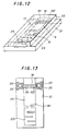
- Fig. 12 is a perspective view of a angular velocity sensor body incorporating an integrally therein made thermostatically-controlled gas path of bent form.
- Fig. 13 is a plan view of a lower semiconductor substrate of the sensor body shown in Fig. 12.
- Fig. 14 is a sectional side view showing a bent gas-path with a connected thereto miniature pump.
- Fig. 15 is a characteristic diagram showing results of measurements of noise components included in outputs of sensors, one having a bent gas-path and other having no bent gas-path.
- Fig. 16 is a sectional side view showing a bent gas-path with a connected thereto miniature pump in another embodiment of the present invention.
- Fig. 1 shows a structure of a gas flow type angular velocity sensor according to the present invention, which body includes a nozzle portion 2 and a gas path 1 with a pair of heat wires arranged therein and is further provided with a thermostatically-controlled gas path 4 which is directly connected at one end to the upper stream side of the nozzle portion 2 and at the other end to a gas-feeding pump 3.
- This thermostatically-controlled gas path 4 is provided with a heater 5 for heating the wall thereof, a temperature sensor 6 for measuring an actual wall temperature and a controller 7 for turning on and off the heating power supply to the heater 5 to actually maintain the wall temperature at the constant value.
- the sensor having thus thermostatically-controlled gas path 4 of suitably selected length can realize that gas discharged from the pump 4 enters into the thermostatically-controlled gas path 4 and flows therealong, being heated by the heating wall surface; the gas gets about the same temperature as that of heating wall at the exit thereof and then enters into the gas path 1 through the nozzle 2. This assures that gas is always regulated at a constant temperature before entering into the gas path of the sensor body.
- Fig. 2 shows a straight-form thermostatically-controlled gas path which is simple but must have a large length necessary for heating gas flow therein at a constant exit temperature.
- a gas path having a plurality of branches (two branches in the shown case) 41 and 42 is formed in one thermostatically-controlled block 4 which has an increased efficiency of heating a gas flow therein and also has a shorter length.
- the sensor of a reduced size is easy to mount in a saved space.
- Fig. 4 there is shown a further shortened thermostatically-controlled block 4 in which a thermostatically-controlled gas path is made in the bent form.
- the gas heating efficiency is especially improved because a turbulent gas flow is produced at every turns of the bent path in the thermostatically-controlled block 4 which is accordingly shortened in.length.
- Fig. 5 shows another example according to the present invention of a thermostatically-controlled gas path 4 having a plurality of inwardly projecting fines 8, which can increase the gas heating efficiency and therefore realize further shprtening of its block length.
- Fig. 7 shows a result of temperature measurements at points F1 - F5 of a thermostatically-controlled gas-path 4 of bent form shown in Fig. 6 when nitrogen gas of about 23°C was forced to flow through the above-mentioned bent path which wall had been previously heated and maintained at a temperature of 83°C.
- the thermostatically-controlled path 4 of the bent form has an inlet and an outlet both formed in the upper wall portion.
- curves A, B and C represent characteristics obtained at gas flows of 50, 100 and 200 SCCM respectively.
- the gas temperature measured at point F5 near to the outlet (OUT) is about the same as that of the wall of the thermostatically-controlled bent gas-path.
- each branch may be of 1/n in length for allowing 1/n of gas to flow therethrough. Accordingly, the resistance to the gas flow in full length of the gas path is reduced to a very small value of about 1/n 2 . This makes it possible to reduce discharging pressure of the pump 3 necessary for feeding the gas into the thermostatically-controlled gas path.
- the thermostatically-controlled gas path 4 having a plurality of internally projecting fines 8 as shown in Fig. 5 may also have the same advantage as mentioned above.
- Fig. 8 shows an embodiment of a gas flow type angular velocity sensor which is composed of semiconductor substrates manufactured by use of micro-machining technology.
- the angular velocity sensor comprises a sensor body 9 for detecting a deflection of a gas flow forced into a gas path through a nozzle portion by use of a pair of heat wires arranged in the gas path; a thermostatically-controlled gas path 10 made within a semiconductor substrate by use of micro-machining technology, which is provided at its bottom with a heater substrate 11 and is directly connected to the nozzle portion of the sensor body; a miniature pump 12 for supplying gas into the thermostatically-controlled gas path 10-; an IC chip 13 which includes an angular velocity detecting circuit, a detecting signal amplifier circuit and a heater drive control circuit for driving the heater substrate 11 so as to maintain the wall temperature of the thermostatically-controlled gas path 10 at a constant value by regulating wall temperature measured by a temperature sensor (not shown); a ceramic substrate 14 with wiring patterns formed thereon for mounting all above-mentioned components at predetermined positions thereon; and a can-type package 15 which contains the ceramic substrate 14 with all installed thereon components and is filled with gas medium such as
- a sensor body 9 formed on semiconductor substrates by using micro-machining technology will be described in detail.
- the gas path as defined in this sensor body does not correspond to the principle of the present invention.
- the sensor body is constructed in such a way that a lower semiconductor substrate 91 having an etched thereon half nozzle hole 161 and an etched thereon half groove 171 and an upper semiconductor substrate 92 having an etched thereon half nozzle hole 162 and an etched thereon half groove 172 and are joined with each other so as to make both half holes and half grooves matched to form a nozzle 16 and a gas path 17 in sensor body.
- the lower semiconductor substrate 91 has also an etched thereon bridge portion 18 across the etched half groove 171 of the gas path 17.
- a pair of heat wires 19i and 192 are formed by pattern etching of a layer of heat wire material (e.g., platinum) deposited on the bridge portion 18, and electrodes 20 are formed by like method one at each side of the paired heat wires.
- a layer of heat wire material e.g., platinum
- the thermostatically-controlled gas path 10 (not shown) is constructed in such a way that a lower semiconductor substrate having an etched thereon half groove and an upper semiconductor substrate having an etched thereon half groove are joined together with their half grooves matched to form a gas path 10.
- Figs. 12 and 13 show an example of a gas flow type angular velocity sensor wherein a bent gas-path 23 for damping a pulsing gas flow is formed integrally with a sensor body 9 on semiconductors by micro-machining technology.
- the upper semiconductor substrate 22 has an upper inlet hole 24 for inducing gas into the bent path 23.
- the lower semiconductor substrate 21 has also an etched thereon bridge portion 18 across the etched half groove 171 of the gas path 17.
- a pair of heat wires 191 and 192 are formed by pattern etching of a layer of heat wire material (e.g., platinum) deposited on the bridge portion 18, and electrodes 20 are formed by like method one at each side of the paired heat wires.
- a layer of heat wire material e.g., platinum
- Fig. 14 shows an embodiment of a gas flow type angular velocity sensor wherein a miniature pump 25 being drivable by a piezoelectric element is directly connected at its discharge port to an inlet port of a bent gas path 23 integrally formed in a sensor body 9 so as to supply gas (e.g., helium) into the bent path.
- gas e.g., helium
- the gas is supplied by the miniature pump 25 into the bent gas path 23 wherein the gas flow is damped enough to eliminate noise components such as pulsation flows due to pumping operations, and then a stabilized flow is injected into the gas path 17 of the sensor body 9.
- Fig. 15 is a characteristic diagram showing results of measurements of noise components included in outputs of sensors, one having a bent path (curve A) and other having no bent path (curve B). As apparent from the diagram, the provision of the bent path 23 can effectively reduce noise components in the sensor outputs.
- a stabilized gas flow without pulsation or the like noise components in a gas path 17 by providing a bent path 23 at a gas outlet 26 of the gas path 17 (not at nozzle side 16) and directly connecting its outlet 27 to a suction port of a miniature pump 25 by which gas is drawn out from the bent path 23 and discharged into an open loop of gas circulation.
- the miniature pump 25 is installed at the upper wall surface of the bent gas-path 23.
- the bent path 23 may have its outlet or inlet opening at any side or bottom wall surface whereon the miniature pump 25 is desired to be installed.
- a gas path having a plurality of inwardly projecting fines is also effective to damp pulsing gas flows produced by pumping operations. This assures to supply a stabilized gas flow into the gas path in the sensor body.
- the gas flow type angular velocity sensor offers such an advantage that a thermostatically-controlled gas path provided at upper stream side of a nozzle portion of the sensor body is capable of maintaining its wall temperature at a constant level through heater control and gas may be heated therein to a constant temperature and then enters into the sensor body through the nozzle, thereby the necessity of heating the sensor body is eliminated and the gas flow is quickly heated up to the constant temperature by use of relatively simple heating means that may have a relatively small heat capacity and an increased response. Accordingly, the sensor may be quickly prepared for working and perform accurate determination of an angular velocity with no affection of ambient temperature variations.
- Another advantage of the gas flow type angular velocity sensor according to the present invention is that the noise components such as pulsing gas flows due to pumping operations can be effectively eliminated in a gas-flow pulsation damping path provided between a pump and a gas path of the sensor body, thereby a stabilized gas flow is insuced in the gas path of the sensor body and its deflection is accurately determined without fluctuation of the sensor's output.
Description
- The present invention relates to a gas flow type angular velocity sensor which is capable of electrically sensing a deflection of a gas flow, which is caused by the action of an angular velocity applied to the sensor body, as defined in the preamble parts of claim 1 and
claim 2. - Japanese laid open patent publication No. 4623/89 describes a gas flow type angular velocity sensor in which gas is forced into a gas path in the sensor body through a nozzle hole to flow thereaiong toward a pair of heat wires, each being composed of a thermo-sensitive resistance element. When an angular velocity is applied to the sensor body, the gas flow is deflected and, accordingly, a difference between thermosensitive outputs of two heat wires is produced and picked up for determining therefrom a direction and a magnitude of the angular velocity acting on the sensor body.
- Since the above-mentioned angular velocity sensor is designed to determine an angular velocity by sensing a very small differential change of heat radiation of two heat wires (i.e., thermosensitive resistances), temperature variation of the gas flow may affect the detecting accuracy of the sensor. For this reason, the conventional gas flow type sensor is mounted in a thermostat capable of keeping temperature therein at a constant level with no affection of ambient temperature variations.
- Recently, there has been also developed a gas rate sensor of the type that its body portion composed of a gas path and a pair of arranged therein heat wires is manufactured by semiconductor micro-machining on the basis of IC technology. This is disclosed in Japanese laid open patent publication No. 29858/92.
- However, in contrast to a conventional gas rate sensor having a relatively large volume of a gas path enough to absorb pulsation and fluctuation of the gas flow produced by a pump that alternately sucks and exhausts gas, the gas rate sensor of smaller volume of its gas path can not absorb the above-mentioned pulsation or fluctuation of the gas flow, which appears as a noise component in the sensor's output. This results in lowering the accuracy of angular velocity measurement.
- The above-mentioned prior arts have the following problems to be solved:
- 1) The first problem is that the thermostat containing a sensor body requires the provision of heating means of relatively large output power so as to evenly heat up the inner space of the thermostat. It also takes time to heat up the thermostat until its inside temperature rises to a constant level, at which the sensor can accurately measure an angular velocity. Furthermore, the response of the thermostat temperature control is somewhat insufficient to prevent the possible affection of ambient temperature variations.
- 2) The second problem arising in using a small-sized sensor having a reduced volume of a gas path is that pulsing gas flows created by pumping operations can not be absorbed in the gas path and produce noise components which may be induced into outputs of the sensor.
-
- An angular velocity sensor according to the preamble parts of
claims 1 and 2 is known from DE-A-31 12 259. In this document there is shown an angular velocity sensor comprising two coaxially arranged tubular members. In a space defined between an outer and an inner member of these two members there is provided a gas path portion into which gas can enter from a gas pump at a first axial end thereof. At a second axial end the gas is leaving this gas path portion and is entering a further gas path portion arranged coaxially to the first-named gas path portion and which is within the inner one of the tube members. The outer one of the tube members is surrounded by a heat wire for heating the gas flowing through the first-named gas path portion in order to provided a substantially constant temperature of the gas. The first-named gas part portion is subdivided in three branches which open into a common supply chamber. Therefore, the flow velocity of the gas flowing from the common supply chamber into the three branches is increased leading to a reduced dwell time of the gas in the respective branches. Therefore, the problem arises that a substantially constant gas temperature cannot be guaranteed. - It is the object of the present invention to provide a gas flow type angular velocity sensor having an enhanced thermostatical control behavior for the gas flowing therethrough.
- According to the present invention, this object is solved by the gas flow type angular velocity sensor as defined in claim 1 and in
claim 2. - On the basis of the fact that a gas flow type angular velocity sensor not mounted in a thermostat can accurately sense a deflection of a gas flow therein by use of thermo-sensitive elements if the gas forced into the gas path in the sensor body through a nozzle hole could be always kept at a constant temperature, the applicant has developed such a gas flow type angular velocity sensor that is provided at the upper stream side of its nozzle portion with a thermostatically-controlled gas path which wall is evenly heated and kept at a constant temperature.
- The applicant has also proposed a gas flow type angular velocity sensor wherein a pump and a gas path are communicated with each other by means of a path having a plurality of internally formed fines for damping a pulsation flow of gas supplied by the pump.
- Fig. 1 is a block diagram showing a structure of a gas flow type angular velocity sensor embodying the present invention.
- Fig. 2 is a cross-sectional plan view showing an example of a thermostatically-controlled gas path.
- Fig. 3 is a view, partly in cross-sectional plan and partly in vertical cross-section, of another example of a thermostatically-controlled gas path.
- Fig. 4 is a cross-sectional plan view showing another example of a thermostatically-controlled gas path.
- Fig. 5 is a view, partly in cross-sectional plan and partly in vertical cross-section, of a further example of a thermostatically-controlled gas path.
- Fig. 6 is a cross-sectional plan view showing another example of a thermostatically-controlled gas path.
- Fig. 7 is a temperature characteristic diagram of gas flow measured at control positions of the thermostatically-controlled gas path shown in Fig. 6.
- Fig. 8 is a sectional front view of a gas flow type angular velocity sensor embodying the present invention.
- Fig. 9 is a perspective view of a body of a gas flow type angular velocity sensor.
- Fig. 10 is a plan view of a lower semiconductor substrate of the sensor body shown in Fig. 9.
- Fig. 11 is a sectional view taken along the plane A-A of Fig. 9.
- Fig. 12 is a perspective view of a angular velocity sensor body incorporating an integrally therein made thermostatically-controlled gas path of bent form.
- Fig. 13 is a plan view of a lower semiconductor substrate of the sensor body shown in Fig. 12.
- Fig. 14 is a sectional side view showing a bent gas-path with a connected thereto miniature pump.
- Fig. 15 is a characteristic diagram showing results of measurements of noise components included in outputs of sensors, one having a bent gas-path and other having no bent gas-path.
- Fig. 16 is a sectional side view showing a bent gas-path with a connected thereto miniature pump in another embodiment of the present invention.
- An embodiment of the present invention will be now described by way of example and with reference to the accompanying drawings.
- Fig. 1 shows a structure of a gas flow type angular velocity sensor according to the present invention, which body includes a
nozzle portion 2 and a gas path 1 with a pair of heat wires arranged therein and is further provided with a thermostatically-controlledgas path 4 which is directly connected at one end to the upper stream side of thenozzle portion 2 and at the other end to a gas-feeding pump 3. This thermostatically-controlledgas path 4 is provided with aheater 5 for heating the wall thereof, atemperature sensor 6 for measuring an actual wall temperature and acontroller 7 for turning on and off the heating power supply to theheater 5 to actually maintain the wall temperature at the constant value. The sensor having thus thermostatically-controlledgas path 4 of suitably selected length can realize that gas discharged from thepump 4 enters into the thermostatically-controlledgas path 4 and flows therealong, being heated by the heating wall surface; the gas gets about the same temperature as that of heating wall at the exit thereof and then enters into the gas path 1 through thenozzle 2. This assures that gas is always regulated at a constant temperature before entering into the gas path of the sensor body. - Fig. 2 shows a straight-form thermostatically-controlled gas path which is simple but must have a large length necessary for heating gas flow therein at a constant exit temperature.
- Accordingly, as shown in Fig. 3, according to the invention a gas path having a plurality of branches (two branches in the shown case) 41 and 42 is formed in one thermostatically-controlled
block 4 which has an increased efficiency of heating a gas flow therein and also has a shorter length. The sensor of a reduced size is easy to mount in a saved space. - In Fig. 4, there is shown a further shortened thermostatically-controlled
block 4 in which a thermostatically-controlled gas path is made in the bent form. In this case, the gas heating efficiency is especially improved because a turbulent gas flow is produced at every turns of the bent path in the thermostatically-controlledblock 4 which is accordingly shortened in.length. - Fig. 5 shows another example according to the present invention of a thermostatically-controlled
gas path 4 having a plurality of inwardly projectingfines 8, which can increase the gas heating efficiency and therefore realize further shprtening of its block length. - Fig. 7 shows a result of temperature measurements at points F1 - F5 of a thermostatically-controlled gas-
path 4 of bent form shown in Fig. 6 when nitrogen gas of about 23°C was forced to flow through the above-mentioned bent path which wall had been previously heated and maintained at a temperature of 83°C. The thermostatically-controlledpath 4 of the bent form has an inlet and an outlet both formed in the upper wall portion. In Fig. 7, curves A, B and C represent characteristics obtained at gas flows of 50, 100 and 200 SCCM respectively. In every case, the gas temperature measured at point F5 near to the outlet (OUT) is about the same as that of the wall of the thermostatically-controlled bent gas-path. - When a gas flow is evenly distributed to "n" branches of a thermostatically-controlled gas path as shown in Fig. 3, each branch may be of 1/n in length for allowing 1/n of gas to flow therethrough. Accordingly, the resistance to the gas flow in full length of the gas path is reduced to a very small value of about 1/n2. This makes it possible to reduce discharging pressure of the pump 3 necessary for feeding the gas into the thermostatically-controlled gas path.
- The thermostatically-controlled
gas path 4 having a plurality of internally projectingfines 8 as shown in Fig. 5 may also have the same advantage as mentioned above. - Fig. 8 shows an embodiment of a gas flow type angular velocity sensor which is composed of semiconductor substrates manufactured by use of micro-machining technology.
- In Fig. 8, the angular velocity sensor comprises a
sensor body 9 for detecting a deflection of a gas flow forced into a gas path through a nozzle portion by use of a pair of heat wires arranged in the gas path; a thermostatically-controlledgas path 10 made within a semiconductor substrate by use of micro-machining technology, which is provided at its bottom with a heater substrate 11 and is directly connected to the nozzle portion of the sensor body; aminiature pump 12 for supplying gas into the thermostatically-controlled gas path 10-; anIC chip 13 which includes an angular velocity detecting circuit, a detecting signal amplifier circuit and a heater drive control circuit for driving the heater substrate 11 so as to maintain the wall temperature of the thermostatically-controlledgas path 10 at a constant value by regulating wall temperature measured by a temperature sensor (not shown); aceramic substrate 14 with wiring patterns formed thereon for mounting all above-mentioned components at predetermined positions thereon; and a can-type package 15 which contains theceramic substrate 14 with all installed thereon components and is filled with gas medium such as helium, nitrogen or likes. In the can-type package, theminiature pump 12 intakes gas from the inner open space of the package and feeds it into thesensor body 9 through the thermostatically-controlledgas path 10 to create a circulation of gas medium. This produces thermally stabilized gas flow to the sensor body. - Referring now to Figs. 9 - 11, an example of a
sensor body 9 formed on semiconductor substrates by using micro-machining technology will be described in detail. The gas path as defined in this sensor body does not correspond to the principle of the present invention. - The sensor body is constructed in such a way that a
lower semiconductor substrate 91 having an etched thereonhalf nozzle hole 161 and an etched thereonhalf groove 171 and anupper semiconductor substrate 92 having an etched thereon half nozzle hole 162 and an etched thereon half groove 172 and are joined with each other so as to make both half holes and half grooves matched to form anozzle 16 and agas path 17 in sensor body. - The
lower semiconductor substrate 91 has also an etchedthereon bridge portion 18 across theetched half groove 171 of thegas path 17. A pair ofheat wires 19i and 192 are formed by pattern etching of a layer of heat wire material (e.g., platinum) deposited on thebridge portion 18, andelectrodes 20 are formed by like method one at each side of the paired heat wires. - The thermostatically-controlled gas path 10 (not shown) is constructed in such a way that a lower semiconductor substrate having an etched thereon half groove and an upper semiconductor substrate having an etched thereon half groove are joined together with their half grooves matched to form a
gas path 10. - It is obviously understood that the above-described invention which will be claimed in
claims 1, 2 and 3 is applied not only to a gas flow type angular velocity sensors formed on semiconductor substrates by micro-machining method but also to gas flow type angular velocity sensors manufactured by general machining methods. - Figs. 12 and 13 show an example of a gas flow type angular velocity sensor wherein a bent gas-
path 23 for damping a pulsing gas flow is formed integrally with asensor body 9 on semiconductors by micro-machining technology. - A lower and an
upper semiconductor substrates half hole 161 of anozzle hole 16, an etched thereonhalf groove 171 of agas path 17 and anetched half groove 231 of abent path 23, are joined together so as to precisely form thenozzle 16, thegas path 17 and thebent path 23 in one integral unit. - The
upper semiconductor substrate 22 has anupper inlet hole 24 for inducing gas into thebent path 23. - The
lower semiconductor substrate 21 has also an etchedthereon bridge portion 18 across theetched half groove 171 of thegas path 17. A pair ofheat wires bridge portion 18, andelectrodes 20 are formed by like method one at each side of the paired heat wires. - Fig. 14 shows an embodiment of a gas flow type angular velocity sensor wherein a
miniature pump 25 being drivable by a piezoelectric element is directly connected at its discharge port to an inlet port of abent gas path 23 integrally formed in asensor body 9 so as to supply gas (e.g., helium) into the bent path. The gas is supplied by theminiature pump 25 into thebent gas path 23 wherein the gas flow is damped enough to eliminate noise components such as pulsation flows due to pumping operations, and then a stabilized flow is injected into thegas path 17 of thesensor body 9. - Fig. 15 is a characteristic diagram showing results of measurements of noise components included in outputs of sensors, one having a bent path (curve A) and other having no bent path (curve B). As apparent from the diagram, the provision of the
bent path 23 can effectively reduce noise components in the sensor outputs. - It is, of course, possible to separately form the
sensor body 9 and thebent path 23 and then join them together. - As shown in Fig. 16, it is also possible to produce a stabilized gas flow without pulsation or the like noise components in a
gas path 17 by providing abent path 23 at agas outlet 26 of the gas path 17 (not at nozzle side 16) and directly connecting itsoutlet 27 to a suction port of aminiature pump 25 by which gas is drawn out from thebent path 23 and discharged into an open loop of gas circulation. - In both cases of Figs. 14 and 16 the
miniature pump 25 is installed at the upper wall surface of the bent gas-path 23. However, it is simply understood that thebent path 23 may have its outlet or inlet opening at any side or bottom wall surface whereon theminiature pump 25 is desired to be installed. - The provision of a gas path having a plurality of inwardly projecting fines (not shown) is also effective to damp pulsing gas flows produced by pumping operations. This assures to supply a stabilized gas flow into the gas path in the sensor body.
- As be apparent from the foregoing description, the gas flow type angular velocity sensor according to the present invention offers such an advantage that a thermostatically-controlled gas path provided at upper stream side of a nozzle portion of the sensor body is capable of maintaining its wall temperature at a constant level through heater control and gas may be heated therein to a constant temperature and then enters into the sensor body through the nozzle, thereby the necessity of heating the sensor body is eliminated and the gas flow is quickly heated up to the constant temperature by use of relatively simple heating means that may have a relatively small heat capacity and an increased response. Accordingly, the sensor may be quickly prepared for working and perform accurate determination of an angular velocity with no affection of ambient temperature variations.
- Another advantage of the gas flow type angular velocity sensor according to the present invention is that the noise components such as pulsing gas flows due to pumping operations can be effectively eliminated in a gas-flow pulsation damping path provided between a pump and a gas path of the sensor body, thereby a stabilized gas flow is insuced in the gas path of the sensor body and its deflection is accurately determined without fluctuation of the sensor's output.
Claims (3)
- A gas flow type angular velocity sensor, comprising:characterized in that said plurality of separate gas path branches is arranged such as to provide a reduced gas flow resistance with respect to the gas flow resistance in the region of said inlet portion.a sensor body,a first gas path portion (1) provided in said sensor body on a downstream side of a nozzle (2),a pair of thermosensitive resistance elements in said first gas path portion (1), providing a thermosensitive output changeable in accordance with a deflection of a flow of gas generated by a pump (3) into the first gas path portion (1) of the sensor body through said nozzle (2), an angular velocity being determined in accordance with said thermosensitive output of the thermosensitive resistance elements,a second gas path portion (4) arranged on an upstream side of said nozzle (2), said second gas path portion (4) being a thermostatically controlled gas path portion which by means of a heater (5) is maintained at a constant temperature, said second gas path portion (4) extending between an inlet portion thereof for receiving a gas flow from said pump (3) and an outlet portion thereof communicating with said nozzle (2) for discharging said gas flow into said first gas path portion (1), said second gas path portion (4) comprising a plurality of separate gas path branches extending between said inlet portion and said outlet portion,
- A gas flow type angular velocity sensor, comprising:characterized in that said thermostatically controlled second gas path portion (4) has a plurality of inwardly projecting fins (8) formed on an internal wall thereof.a sensor body,a first gas path portion (1) provided in said sensor body on a downstream side of a nozzle (2),a pair of thermosensitive resistance elements in said first gas path portion (1), providing a thermosensitive output changeable in accordance with a deflection of a flow of gas into the first gas path portion (1) of the sensor body through said nozzle (2), an angular velocity being determined in accordance with said thermosensitive output of the thermosensitive resistance elements,a second gas path portion (4) arranged on an upstream side of said nozzle (2), said second gas path portion (4) being a thermostatically controlled gas path portion which by means of a heater (5) is maintained at a constant temperature,
- Gas flow type angular velocity sensor according to claims 1 or 2, further comprising a temperature sensor (6) for measuring a wall temperature of said second gas path portion and a controller (7) for controlling said heater (5) such as to maintain the wall temperature at a constant value.
Applications Claiming Priority (5)
| Application Number | Priority Date | Filing Date | Title |
|---|---|---|---|
| JP135536/92 | 1992-04-10 | ||
| JP13553692A JP3141215B2 (en) | 1992-04-10 | 1992-04-10 | Gas rate sensor |
| JP14473192A JPH05297008A (en) | 1992-04-20 | 1992-04-20 | Gas angular velocity detector |
| JP144731/92 | 1992-04-20 | ||
| EP93105795A EP0569706B1 (en) | 1992-04-10 | 1993-04-07 | Gas flow type angular velocity sensor |
Related Parent Applications (2)
| Application Number | Title | Priority Date | Filing Date |
|---|---|---|---|
| EP93105795.4 Division | 1993-04-07 | ||
| EP93105795A Division EP0569706B1 (en) | 1992-04-10 | 1993-04-07 | Gas flow type angular velocity sensor |
Publications (3)
| Publication Number | Publication Date |
|---|---|
| EP0713098A2 EP0713098A2 (en) | 1996-05-22 |
| EP0713098A3 EP0713098A3 (en) | 1996-06-19 |
| EP0713098B1 true EP0713098B1 (en) | 1999-05-12 |
Family
ID=26469371
Family Applications (2)
| Application Number | Title | Priority Date | Filing Date |
|---|---|---|---|
| EP95120416A Expired - Lifetime EP0713098B1 (en) | 1992-04-10 | 1993-04-07 | Gas flow type angular velocity sensor |
| EP93105795A Expired - Lifetime EP0569706B1 (en) | 1992-04-10 | 1993-04-07 | Gas flow type angular velocity sensor |
Family Applications After (1)
| Application Number | Title | Priority Date | Filing Date |
|---|---|---|---|
| EP93105795A Expired - Lifetime EP0569706B1 (en) | 1992-04-10 | 1993-04-07 | Gas flow type angular velocity sensor |
Country Status (3)
| Country | Link |
|---|---|
| US (1) | US5385046A (en) |
| EP (2) | EP0713098B1 (en) |
| DE (2) | DE69315253T2 (en) |
Families Citing this family (24)
| Publication number | Priority date | Publication date | Assignee | Title |
|---|---|---|---|---|
| DE69510569T2 (en) * | 1994-01-20 | 1999-10-28 | Honda Motor Co Ltd | Accelerometer |
| JP3247533B2 (en) * | 1994-02-04 | 2002-01-15 | 本田技研工業株式会社 | Manufacturing method of semiconductor gas rate sensor |
| JP3244208B2 (en) * | 1994-02-07 | 2002-01-07 | 本田技研工業株式会社 | Gas rate detector |
| JP3312227B2 (en) * | 1994-02-23 | 2002-08-05 | 本田技研工業株式会社 | Gas angular velocity sensor |
| JP3281169B2 (en) * | 1994-03-24 | 2002-05-13 | 本田技研工業株式会社 | Multi-axis gas rate sensor |
| US5786744A (en) * | 1994-03-24 | 1998-07-28 | Honda Giken Kogyo Kabushiki Kaisha | Hybrid sensor |
| US6655207B1 (en) | 2000-02-16 | 2003-12-02 | Honeywell International Inc. | Flow rate module and integrated flow restrictor |
| US6591674B2 (en) * | 2000-12-21 | 2003-07-15 | Honeywell International Inc. | System for sensing the motion or pressure of a fluid, the system having dimensions less than 1.5 inches, a metal lead frame with a coefficient of thermal expansion that is less than that of the body, or two rtds and a heat source |
| CN100453972C (en) * | 2007-06-01 | 2009-01-21 | 北京沃尔康科技有限责任公司 | Gas pendulum inertia sensor |
| DK2180951T3 (en) * | 2007-08-21 | 2019-12-02 | Belimo Holding Ag | FLOW SENSOR AND PREPARATION PROCEDURE |
| US8397586B2 (en) * | 2010-03-22 | 2013-03-19 | Honeywell International Inc. | Flow sensor assembly with porous insert |
| US8656772B2 (en) | 2010-03-22 | 2014-02-25 | Honeywell International Inc. | Flow sensor with pressure output signal |
| US8113046B2 (en) | 2010-03-22 | 2012-02-14 | Honeywell International Inc. | Sensor assembly with hydrophobic filter |
| US8756990B2 (en) | 2010-04-09 | 2014-06-24 | Honeywell International Inc. | Molded flow restrictor |
| US20110252882A1 (en) * | 2010-04-19 | 2011-10-20 | Honeywell International Inc. | Robust sensor with top cap |
| US9003877B2 (en) | 2010-06-15 | 2015-04-14 | Honeywell International Inc. | Flow sensor assembly |
| US8418549B2 (en) | 2011-01-31 | 2013-04-16 | Honeywell International Inc. | Flow sensor assembly with integral bypass channel |
| US8356514B2 (en) | 2011-01-13 | 2013-01-22 | Honeywell International Inc. | Sensor with improved thermal stability |
| CN102135438A (en) * | 2011-01-13 | 2011-07-27 | 中国工程物理研究院电子工程研究所 | Temperature control device for micro sensor |
| US8695417B2 (en) | 2011-01-31 | 2014-04-15 | Honeywell International Inc. | Flow sensor with enhanced flow range capability |
| US9052217B2 (en) | 2012-11-09 | 2015-06-09 | Honeywell International Inc. | Variable scale sensor |
| US9470593B2 (en) | 2013-09-12 | 2016-10-18 | Honeywell International Inc. | Media isolated pressure sensor |
| JP6446985B2 (en) | 2014-10-10 | 2019-01-09 | 株式会社島津製作所 | Thermal conductivity detector and gas chromatograph |
| US9952079B2 (en) | 2015-07-15 | 2018-04-24 | Honeywell International Inc. | Flow sensor |
Family Cites Families (9)
| Publication number | Priority date | Publication date | Assignee | Title |
|---|---|---|---|---|
| US4254659A (en) * | 1979-01-12 | 1981-03-10 | Kbg Corporation | Fluid dynamic angular rate sensor |
| JPS5945944B2 (en) * | 1980-03-27 | 1984-11-09 | 本田技研工業株式会社 | gas rate sensor |
| US4295373A (en) * | 1980-04-03 | 1981-10-20 | United Technologies Corporation | Fluidic angular rate sensor with integrated impulse jet pump assembly |
| JPS57200812A (en) * | 1981-06-05 | 1982-12-09 | Honda Motor Co Ltd | Running path displaying device |
| JPS60257365A (en) * | 1984-06-05 | 1985-12-19 | Komatsu Ltd | Rotation angle speed detector |
| US4584878A (en) * | 1984-09-24 | 1986-04-29 | Tamagawa Seigi Kabushiki Kaisha | Gas-rate sensor |
| JPS644623A (en) * | 1987-06-26 | 1989-01-09 | Nippon Telegraph & Telephone | Polymer thin film and its preparation |
| JP2721840B2 (en) * | 1989-06-28 | 1998-03-04 | 本田技研工業株式会社 | Gas angular velocity detector |
| JPH0830710B2 (en) * | 1990-03-08 | 1996-03-27 | 本田技研工業株式会社 | Angular velocity detector |
-
1993
- 1993-03-31 US US08/040,937 patent/US5385046A/en not_active Expired - Lifetime
- 1993-04-07 DE DE69315253T patent/DE69315253T2/en not_active Expired - Fee Related
- 1993-04-07 DE DE69324936T patent/DE69324936T2/en not_active Expired - Fee Related
- 1993-04-07 EP EP95120416A patent/EP0713098B1/en not_active Expired - Lifetime
- 1993-04-07 EP EP93105795A patent/EP0569706B1/en not_active Expired - Lifetime
Also Published As
| Publication number | Publication date |
|---|---|
| DE69324936T2 (en) | 1999-09-16 |
| EP0569706A2 (en) | 1993-11-18 |
| EP0713098A2 (en) | 1996-05-22 |
| DE69315253D1 (en) | 1998-01-02 |
| EP0569706B1 (en) | 1997-11-19 |
| DE69315253T2 (en) | 1998-03-19 |
| US5385046A (en) | 1995-01-31 |
| EP0713098A3 (en) | 1996-06-19 |
| DE69324936D1 (en) | 1999-06-17 |
| EP0569706A3 (en) | 1994-01-26 |
Similar Documents
| Publication | Publication Date | Title |
|---|---|---|
| EP0713098B1 (en) | Gas flow type angular velocity sensor | |
| CN101680788B (en) | Heat flowmeter | |
| US3992940A (en) | Solid state fluid flow sensor | |
| US4125093A (en) | Solid state fluid flow sensor | |
| EP1087213B1 (en) | Hot-wire type air flow meter for internal combustion engine | |
| JP3758111B2 (en) | Air flow measurement device | |
| US5012676A (en) | Gas rate sensor system | |
| RU2151380C1 (en) | Device measuring mass flow rate of fluid medium | |
| US5107707A (en) | Gas flow type angular velocity sensor | |
| US6725716B1 (en) | Thermo-sensitive flow rate sensor and method of manufacturing the same | |
| EP0669536B1 (en) | Gas flow type angular velocity sensor | |
| US6301960B1 (en) | Thermo-sensitive flow rate sensor | |
| KR100464768B1 (en) | Thermosensitive flow rate sensor | |
| KR100244360B1 (en) | Process and device for measuring air flow | |
| JPH01180460A (en) | Gas rate sensor | |
| US20050022593A1 (en) | Fluid flow sensor | |
| US7347092B1 (en) | Apparatus and method for fluid flow measurement | |
| EP0459468B1 (en) | Hot-wire type flowmeter | |
| JP2008096453A (en) | Heating device for sensor, sensor, and acceleration sensor | |
| US11802784B1 (en) | Single heater MEMS-CMOS based flow sensor | |
| US11788874B1 (en) | Self-powered, matched wheatstone bridge flow sensor | |
| JP3177803B2 (en) | Gas angular velocity detector | |
| JPH05297008A (en) | Gas angular velocity detector | |
| JPH0329859A (en) | Gas type angular velocity detector | |
| KR100692072B1 (en) | Flow sensor and sensing apparatus having the cooling line |
Legal Events
| Date | Code | Title | Description |
|---|---|---|---|
| PUAI | Public reference made under article 153(3) epc to a published international application that has entered the european phase |
Free format text: ORIGINAL CODE: 0009012 |
|
| PUAL | Search report despatched |
Free format text: ORIGINAL CODE: 0009013 |
|
| 17P | Request for examination filed |
Effective date: 19951222 |
|
| AC | Divisional application: reference to earlier application |
Ref document number: 569706 Country of ref document: EP |
|
| AK | Designated contracting states |
Kind code of ref document: A2 Designated state(s): DE FR GB |
|
| AK | Designated contracting states |
Kind code of ref document: A3 Designated state(s): DE FR GB |
|
| 17Q | First examination report despatched |
Effective date: 19970210 |
|
| GRAG | Despatch of communication of intention to grant |
Free format text: ORIGINAL CODE: EPIDOS AGRA |
|
| GRAG | Despatch of communication of intention to grant |
Free format text: ORIGINAL CODE: EPIDOS AGRA |
|
| GRAH | Despatch of communication of intention to grant a patent |
Free format text: ORIGINAL CODE: EPIDOS IGRA |
|
| GRAH | Despatch of communication of intention to grant a patent |
Free format text: ORIGINAL CODE: EPIDOS IGRA |
|
| GRAA | (expected) grant |
Free format text: ORIGINAL CODE: 0009210 |
|
| AC | Divisional application: reference to earlier application |
Ref document number: 569706 Country of ref document: EP |
|
| AK | Designated contracting states |
Kind code of ref document: B1 Designated state(s): DE FR GB |
|
| REF | Corresponds to: |
Ref document number: 69324936 Country of ref document: DE Date of ref document: 19990617 |
|
| ET | Fr: translation filed | ||
| PLBE | No opposition filed within time limit |
Free format text: ORIGINAL CODE: 0009261 |
|
| STAA | Information on the status of an ep patent application or granted ep patent |
Free format text: STATUS: NO OPPOSITION FILED WITHIN TIME LIMIT |
|
| 26N | No opposition filed | ||
| REG | Reference to a national code |
Ref country code: GB Ref legal event code: IF02 |
|
| PGFP | Annual fee paid to national office [announced via postgrant information from national office to epo] |
Ref country code: DE Payment date: 20040130 Year of fee payment: 12 |
|
| PGFP | Annual fee paid to national office [announced via postgrant information from national office to epo] |
Ref country code: GB Payment date: 20040331 Year of fee payment: 12 |
|
| PGFP | Annual fee paid to national office [announced via postgrant information from national office to epo] |
Ref country code: FR Payment date: 20040428 Year of fee payment: 12 |
|
| PG25 | Lapsed in a contracting state [announced via postgrant information from national office to epo] |
Ref country code: GB Free format text: LAPSE BECAUSE OF NON-PAYMENT OF DUE FEES Effective date: 20050407 |
|
| PG25 | Lapsed in a contracting state [announced via postgrant information from national office to epo] |
Ref country code: DE Free format text: LAPSE BECAUSE OF NON-PAYMENT OF DUE FEES Effective date: 20051101 |
|
| GBPC | Gb: european patent ceased through non-payment of renewal fee |
Effective date: 20050407 |
|
| PG25 | Lapsed in a contracting state [announced via postgrant information from national office to epo] |
Ref country code: FR Free format text: LAPSE BECAUSE OF NON-PAYMENT OF DUE FEES Effective date: 20051230 |
|
| REG | Reference to a national code |
Ref country code: FR Ref legal event code: ST Effective date: 20051230 |