EP0713084B1 - Optical micro-system of rosette strain gauge types with dielectrical guides for measuring a longitudinal strain of a planar structure - Google Patents
Optical micro-system of rosette strain gauge types with dielectrical guides for measuring a longitudinal strain of a planar structure Download PDFInfo
- Publication number
- EP0713084B1 EP0713084B1 EP95402572A EP95402572A EP0713084B1 EP 0713084 B1 EP0713084 B1 EP 0713084B1 EP 95402572 A EP95402572 A EP 95402572A EP 95402572 A EP95402572 A EP 95402572A EP 0713084 B1 EP0713084 B1 EP 0713084B1
- Authority
- EP
- European Patent Office
- Prior art keywords
- rosette
- optical
- strain
- microsystem according
- gauges
- Prior art date
- Legal status (The legal status is an assumption and is not a legal conclusion. Google has not performed a legal analysis and makes no representation as to the accuracy of the status listed.)
- Expired - Lifetime
Links
- 230000003287 optical effect Effects 0.000 title claims description 67
- 230000003595 spectral effect Effects 0.000 claims description 18
- 239000000463 material Substances 0.000 claims description 16
- 230000010287 polarization Effects 0.000 claims description 8
- 230000000694 effects Effects 0.000 claims description 7
- 238000012423 maintenance Methods 0.000 claims description 5
- 238000006073 displacement reaction Methods 0.000 claims description 3
- 239000000835 fiber Substances 0.000 description 47
- 238000005259 measurement Methods 0.000 description 23
- 238000000034 method Methods 0.000 description 21
- 238000001228 spectrum Methods 0.000 description 12
- VYPSYNLAJGMNEJ-UHFFFAOYSA-N Silicium dioxide Chemical group O=[Si]=O VYPSYNLAJGMNEJ-UHFFFAOYSA-N 0.000 description 11
- 230000005540 biological transmission Effects 0.000 description 11
- 239000013307 optical fiber Substances 0.000 description 8
- 238000005305 interferometry Methods 0.000 description 7
- 239000002131 composite material Substances 0.000 description 6
- 230000010363 phase shift Effects 0.000 description 6
- 238000012545 processing Methods 0.000 description 6
- 238000012546 transfer Methods 0.000 description 6
- 238000010276 construction Methods 0.000 description 5
- 238000001514 detection method Methods 0.000 description 5
- 230000004044 response Effects 0.000 description 5
- 239000000377 silicon dioxide Substances 0.000 description 5
- 208000007180 Sunstroke Diseases 0.000 description 4
- 230000008901 benefit Effects 0.000 description 4
- 238000013461 design Methods 0.000 description 4
- 230000035945 sensitivity Effects 0.000 description 4
- YMWUJEATGCHHMB-UHFFFAOYSA-N Dichloromethane Chemical compound ClCCl YMWUJEATGCHHMB-UHFFFAOYSA-N 0.000 description 3
- 230000006835 compression Effects 0.000 description 3
- 238000007906 compression Methods 0.000 description 3
- 238000004519 manufacturing process Methods 0.000 description 3
- 229910052751 metal Inorganic materials 0.000 description 3
- 239000002184 metal Substances 0.000 description 3
- 230000008569 process Effects 0.000 description 3
- 230000002123 temporal effect Effects 0.000 description 3
- 206010019345 Heat stroke Diseases 0.000 description 2
- 238000013459 approach Methods 0.000 description 2
- 238000004364 calculation method Methods 0.000 description 2
- 238000006243 chemical reaction Methods 0.000 description 2
- 238000000576 coating method Methods 0.000 description 2
- 230000001419 dependent effect Effects 0.000 description 2
- 238000001914 filtration Methods 0.000 description 2
- 239000011521 glass Substances 0.000 description 2
- 238000010348 incorporation Methods 0.000 description 2
- 230000010354 integration Effects 0.000 description 2
- 239000011159 matrix material Substances 0.000 description 2
- 239000004065 semiconductor Substances 0.000 description 2
- 229910000679 solder Inorganic materials 0.000 description 2
- OKTJSMMVPCPJKN-UHFFFAOYSA-N Carbon Chemical compound [C] OKTJSMMVPCPJKN-UHFFFAOYSA-N 0.000 description 1
- 229910052684 Cerium Inorganic materials 0.000 description 1
- YZCKVEUIGOORGS-OUBTZVSYSA-N Deuterium Chemical compound [2H] YZCKVEUIGOORGS-OUBTZVSYSA-N 0.000 description 1
- UFHFLCQGNIYNRP-UHFFFAOYSA-N Hydrogen Chemical compound [H][H] UFHFLCQGNIYNRP-UHFFFAOYSA-N 0.000 description 1
- 206010034972 Photosensitivity reaction Diseases 0.000 description 1
- 238000010521 absorption reaction Methods 0.000 description 1
- PNEYBMLMFCGWSK-UHFFFAOYSA-N aluminium oxide Inorganic materials [O-2].[O-2].[O-2].[Al+3].[Al+3] PNEYBMLMFCGWSK-UHFFFAOYSA-N 0.000 description 1
- 238000004458 analytical method Methods 0.000 description 1
- 230000000712 assembly Effects 0.000 description 1
- 238000000429 assembly Methods 0.000 description 1
- 230000000903 blocking effect Effects 0.000 description 1
- 229910052799 carbon Inorganic materials 0.000 description 1
- GWXLDORMOJMVQZ-UHFFFAOYSA-N cerium Chemical compound [Ce] GWXLDORMOJMVQZ-UHFFFAOYSA-N 0.000 description 1
- 239000011248 coating agent Substances 0.000 description 1
- 230000001427 coherent effect Effects 0.000 description 1
- 230000000295 complement effect Effects 0.000 description 1
- 239000004567 concrete Substances 0.000 description 1
- 239000000470 constituent Substances 0.000 description 1
- 238000007796 conventional method Methods 0.000 description 1
- 238000012937 correction Methods 0.000 description 1
- 230000008878 coupling Effects 0.000 description 1
- 238000010168 coupling process Methods 0.000 description 1
- 238000005859 coupling reaction Methods 0.000 description 1
- 230000006866 deterioration Effects 0.000 description 1
- 229910052805 deuterium Inorganic materials 0.000 description 1
- 238000011161 development Methods 0.000 description 1
- 238000009792 diffusion process Methods 0.000 description 1
- YBMRDBCBODYGJE-UHFFFAOYSA-N germanium oxide Inorganic materials O=[Ge]=O YBMRDBCBODYGJE-UHFFFAOYSA-N 0.000 description 1
- 229910052739 hydrogen Inorganic materials 0.000 description 1
- 239000001257 hydrogen Substances 0.000 description 1
- 230000003993 interaction Effects 0.000 description 1
- 239000007788 liquid Substances 0.000 description 1
- 230000000873 masking effect Effects 0.000 description 1
- 238000000691 measurement method Methods 0.000 description 1
- 230000006855 networking Effects 0.000 description 1
- 230000005693 optoelectronics Effects 0.000 description 1
- PVADDRMAFCOOPC-UHFFFAOYSA-N oxogermanium Chemical compound [Ge]=O PVADDRMAFCOOPC-UHFFFAOYSA-N 0.000 description 1
- 230000000737 periodic effect Effects 0.000 description 1
- 230000036211 photosensitivity Effects 0.000 description 1
- 230000000379 polymerizing effect Effects 0.000 description 1
- KCTAWXVAICEBSD-UHFFFAOYSA-N prop-2-enoyloxy prop-2-eneperoxoate Chemical compound C=CC(=O)OOOC(=O)C=C KCTAWXVAICEBSD-UHFFFAOYSA-N 0.000 description 1
- 230000001902 propagating effect Effects 0.000 description 1
- 238000005086 pumping Methods 0.000 description 1
- 230000005855 radiation Effects 0.000 description 1
- -1 rare earth ions Chemical class 0.000 description 1
- 229910052761 rare earth metal Inorganic materials 0.000 description 1
- 239000012783 reinforcing fiber Substances 0.000 description 1
- 230000003938 response to stress Effects 0.000 description 1
- 230000000717 retained effect Effects 0.000 description 1
- 230000002441 reversible effect Effects 0.000 description 1
- 238000005070 sampling Methods 0.000 description 1
- 238000006467 substitution reaction Methods 0.000 description 1
- 230000008542 thermal sensitivity Effects 0.000 description 1
- 238000003466 welding Methods 0.000 description 1
Images


Classifications
-
- G—PHYSICS
- G01—MEASURING; TESTING
- G01L—MEASURING FORCE, STRESS, TORQUE, WORK, MECHANICAL POWER, MECHANICAL EFFICIENCY, OR FLUID PRESSURE
- G01L1/00—Measuring force or stress, in general
- G01L1/24—Measuring force or stress, in general by measuring variations of optical properties of material when it is stressed, e.g. by photoelastic stress analysis using infrared, visible light, ultraviolet
- G01L1/242—Measuring force or stress, in general by measuring variations of optical properties of material when it is stressed, e.g. by photoelastic stress analysis using infrared, visible light, ultraviolet the material being an optical fibre
- G01L1/246—Measuring force or stress, in general by measuring variations of optical properties of material when it is stressed, e.g. by photoelastic stress analysis using infrared, visible light, ultraviolet the material being an optical fibre using integrated gratings, e.g. Bragg gratings
Definitions
- the present invention relates to an optical microsystem of rosette type of strain gauges with dielectric guides, for measurement of a longitudinal constraint.
- longitudinal constraint will be used to designate a constraint having only one single component.
- gauges or rosettes i.e. an assembled structure of several gauges
- metal or semiconductor tracks such as shown in Figure 2A.
- a gauge measures a known orientation component, while a rosette makes it possible to determine the values of the stresses the main plane of the gauges, as well as the orientation of the main reference by relation to the arrangement of the gauges constituting the rosette.
- gauges or rosettes are therefore electric and temperature compensated in a restricted area of use, by a choice judicious materials.
- An example of such a technical impossibility may be, for example example, the measurement of a stress applied to a rib or a spar of an airplane wing made of composite material.
- knowing that the detectors are embedded in the composite so we must isolate them spatially so that one measures a constraint and that the other is not subjected to it.
- it is not conceivable to place a stress sensor far from its reference sensor in temperature because the temperature differences may be too great.
- the limitation comes from the fact that the detectors have very similar temperature and stress responses because the materials used works differ very little. A very resolute distinction is therefore difficult.
- the first solution requires maintaining the polarization of light (fiber to polarization maintenance), which considerably complicates the implementation of such a measurement device (complex connectivity) and jointly increases its cost.
- the object of the invention is to propose a device making it possible to rigorously overcome temperature fluctuations in a way mathematical, via a procedure for processing the information collected at from a sensor comprising detectors placed close enough to the each other to be at the same temperature.
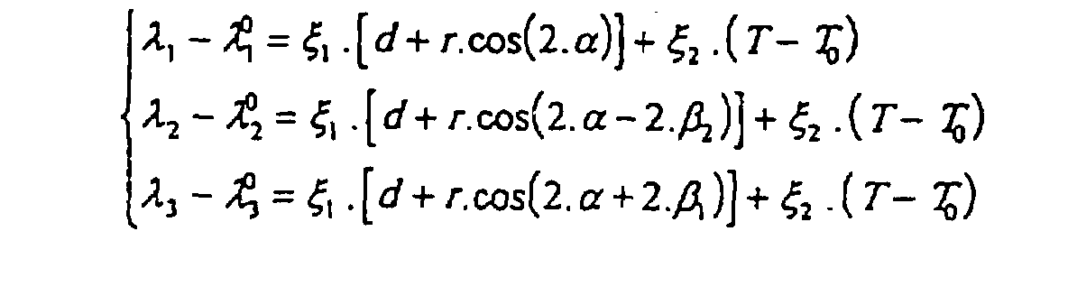
- the present invention relates to an optical microsystem of the rosette type of strain gauges with dielectric guides, intended to measure a set of stresses applied to a part, said microsystem comprising at least one rosette formed of at least two strain gauges. with dielectric guides (J1, J2, J3) of known and non-parallel orientations, characterized in that the strain gauges are Bragg gratings (RB 1 , RB 2 , RB 3 ), in that the part is a part subjected to a constraint of a single component contained in the plane of the gauges, and in that a calculation circuit, which delivers a result independent of the temperature, makes it possible to determine said constraint by resolution of the following system of equations: ⁇ 1 , ⁇ 2 and ⁇ 3 being the respective characteristic wavelengths of the three Bragg gratings constituting the rosette, these wavelengths being very close to one another, and ⁇ 0/1, ⁇ 0/2, and ⁇ 0/3 the characteristic wavelengths in the absence of deformations and at
- a rosette of strain gauges to dielectric guides, in particular with optical fibers, of known principle, intended usually to measure the constraint system, of unknown orientation a a priori, applied to a part at a point, is used, surprisingly, in the case of a part subjected to a constraint having only one component.
- the solution of a system of equations by a calculation circuit allows to determine the constraint, regardless of temperature, if the rosette is formed of two fiber optic angle gauges positioning of the rosette on the part if it is formed by three gauges. This principle is valid for all gauges measuring a variation of optical path under constraint, in particular to photo-registered Bragg networks.
- the rosette is formed of three networks of Bragg placed at 120 ° or 45 ° from each other. These three networks can be registered simultaneously or successively by the same optical beam sunstroke. These three networks may not be registered simultaneously and may have different characteristic wavelengths.
- the dielectric guides are optical fibers.
- This optical micro-system includes at least one guide dielectric, maintaining or not polarizing, in which are incorporated the strain gauges which are elongation transducers, arranged following known non-parallel orientations.
- Transducers elongation which are themselves dielectric guides, can be bonded to the surface, or embedded in a locally planar support material of which the deformations are to be determined.
- these transducers are Bragg gratings which operate by phase tuning effect and the guides are monomode and photosensitive (for example germanosilicate matrix or doped with rare earth ions (Ce 3+ , ...) ).
- the transducers operate by interferometric effect (Fabry-Perot interferometers, Michelson or Mach-Zehnder) and the guides are single-mode.
- interferometric effect Fabry-Perot interferometers, Michelson or Mach-Zehnder
- each gauge measures a variation of optical path as a function of the stress to be measured, which induces a spectral shift (Bragg grating).
- each gauge measures a variation of the optical path as a function of the stress to be measured which induces a interference fringe shift (Fabry-Perot, Michelson interferometers, Mach-Zehnder).
- the optical micro-system of the invention can be such that the gauges constituting the rosette are placed in series on the same guide dielectric.
- the microsystem can also present a configuration of the balanced Sagnac interferometer type using a coupler at 50% reflection in the spectral band of use, this configuration being consisting of a single guide plane and allowing the inclusion of a rosette between two plans of a material.
- the present micro-system thus makes it possible to provide a signal optics for measuring a pure longitudinal stress (traction, compression), regardless of temperature and positioning of this optical micro-system on the support material whose constraints are determine.
- the longitudinal stress sensor thus formed is therefore perfectly suited to an industrial environment (construction site, ...) because it no longer has need temperature correction procedure and can be arranged arbitrarily in any position on a flat part of the part to monitor (beam, mast, panel, ).
- a particularly application interesting is to insert the sensitive fiber within a material of the type composite.
- the fiber can advantageously enter in substitution for several reinforcing fibers (carbon, typically) and keeps the alignment of these fibers.
- the fibers making up the rosette are placed within parallel planes of different orientations. Such a rosette can be inserted into a rib or a spar of a composite airplane wing and the stress information longitudinal can be found regardless of the known orientation (non-parallel) two or three gauges making up this rosette.
- Constraint information can be translated optically from various ways because the micro-system can exploit different principles physical detection (interferometry, phase agreement) insofar as all these principles involve the dielectric guide as a sensor intrinsic, guide whose effective guide index and interaction length both depend on temperature, in addition to constraints.
- the principle of Bragg gratings operating in gauges of constraints is to use the dependence of the reflection spectrum or transmission of this type of transducer subject to local stress (of traction or compression) oriented along the axis of a fiber.
- the network does transmits that the stress oriented along the local axis of the fiber.
- the Bragg grating filters the light in reflection, the waves (incident and reflected) remaining guided.
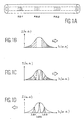
- Figures 1B to 1D illustrate the filtering behavior of three photo-registered Bragg gratings RB1, RB2 and RB3 shown in figure 1A.
- Figures 1B, 1C and 1D are curves of the intensity in function of the wavelength, respectively of the incident spectrum, of the spectrum transmitted and reflected Spectrum.
- Optical fibers are most often single-mode so that all the energy that propagates in a single mode is almost entirely reflected at the tuning wavelength (reflection greater than 95%). In the where the fiber is multimode, the wavelength tuning is different for each mode.
- the exposure changes the local index of refraction so that a spatially periodic insolation creates the network, either by internal insolation (standing waves internal to the guide), or by external insolation (fringes two-wave interference).
- External insolation allows to register a network of any spatial period while internal insolation does not allow to record that a network of the same period as the half wavelength sunstroke.
- Optical transducers based on the use of Bragg provide multiple advantages: they are insensitive to disturbances electromagnetic, allow multiplexing (for example: in length (in the case which concerns us), are of millimeter dimensions (micro-system approach) and lead to resolutions and sensitivities of measurement comparable to conventional methods such as gauges resistive stresses on metallic or semiconductor wires.
- the sensors exploiting the principle of dependence of the tuning wavelength of the Bragg grating as a function of the elongation of said network (following a constraint) are also dependent on the temperature via the coefficient of expansion of the matrix (silica most often) and the thermal sensitivity of its refractive index. In most real applications (except laboratory), the temperature is not controlled and it is easily proven that the elongation due to thermal expansion cannot be neglected in view of the stress-induced elongations that one seeks to measure.
- rosette is not new and rosettes are long used to determine the values of the two constraints principal of the plane as well as the direction of the principal reference mark, if the temperature T is known.
- the principle of a rosette of fiber optic strain gauges was described in a recent publication by T. Valis, D. Hogg and R.M. Measures (Smart Mater. Struct., Vol. 1, 1992, pages 227-232).
- This rosette uses either Fabry-Perot interferometers, or Michelson interferometers like strain gauges as shown in Figures 2B and 2C.
- FIG. 2A represents a conventional (electric) rosette with metal tracks 10
- FIG. 2B represents an optical rosette with Michelson interferometers with measuring arms 11 and a reference arm 12
- Figure 2C shows a optical rosette with Fabry-Perot interferometers (cavity formed by a layer dielectric 68 deposited at the end of the fiber and a semi-reflective weld 13).
- the width e is equal to 125 ⁇ m by example, and length 14 is the sensitive length.
- the originality of the invention lies in the use of this geometry to measure punctually only one constraint but regardless of the temperature and the positioning of the rosette in its plan. It is original in the sense that it allows to rigorously overcome effects of temperature to measure only those due to the efforts of traction / compression to be determined (which is more efficient than the concepts previously cited) on condition that the constraint is purely longitudinal in the case of a single rosette.
- the advantage is that the information can be found whatever either the positioning of the rosette on the surface or within the material support and, that by performing the measurement punctually, there is no longer any need to second reference fiber to overcome temperature.
- This solution therefore solves the problem of cross-sensitivity to constraints and temperature in the case of a longitudinal stress (rib, spar, mast, beam, ...) and solves the problem of finding a reliable temperature reference.
- the invention consists in measuring the differences in lengths wave characteristics of two (or three) networks. These networks can be placed, a priori, in any orientation but not in parallel to each other.
- the rosette consists of only two networks, it is possible to deduce the longitudinal stress exerted, regardless of the temperature, the positioning angle of this rosette relative to the orientation of this constraint being assumed to be known.
- the rosette is made up of three networks, it is possible, this time, to deduce from it the longitudinal stress exerted, regardless of temperature and positioning (i.e. angle what does the orientation of the rosette do with respect to the direction of the stress at determine).
- these three networks making up the rosette are usually placed precisely either at 120 ° or 45 ° from each other so to facilitate the analysis of the results by the use of formulas simpler math.
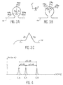
- FIGS. 3A, 3B and 3C represent examples of the configuration of rosettes with three Bragg gratings RB 1 , RB 2 and RB 3 measuring respectively the deformations ⁇ 1 , ⁇ 2 and ⁇ 3 respectively for a rosette at 120 °, a rosette with 45 ° and a 120 ° rosette with Bragg gratings, with three gauges J1, J2 and J3, using a silica 15 optical fiber (photo-writable).
- the networks must be registered in fibers with the same coefficients of thermal expansion. This condition is obviously performed if the fibers are strictly identical (from the same preform). So, if we assume that the transducers of Bragg making up the rosette are close enough to each other to be at the same temperature, measuring differences in wavelengths characteristics independently determine the tensile stress of the temperature.
- ⁇ 1 , ⁇ 2 and ⁇ 3 are the respective characteristic wavelengths of the three Bragg gratings constituting the rosette and ⁇ 0 / 1. ⁇ 0/2 and ⁇ 0/3 the characteristic wavelengths in the absence of deformations and at a reference temperature T 0 .
- the three wavelengths ⁇ 1 , ⁇ 2 and ⁇ 3 are considered to be very close to each other (a few nm apart).
- the two angles ⁇ 1 and ⁇ 2 characterizing the rosette can be any (but not zero modulo ⁇ ) and ⁇ is the angle made by the orientation of the main stress ( ⁇ x ) to be determined with the orientation of the gauge. reference constraints of the rosette (here, the J1 gauge).
- This angle ⁇ is, a priori, unknown and is a function of the positioning tolerances (position of the rosette gauge on the surface of the support material).
- the parameters d and r are respectively the half-sum and the half-difference of the principal strains to be determined.
- the rosette is constructed with any angles ⁇ 1 and ⁇ 2 but perfectly known after manufacture, it is possible to deduce therefrom the main stress of pure traction by solving the system numerically (3).
- the sensor can be continuously optically interrogated or impulsively, using a spectrally wider source or, a contrario, much finer than the spectral width of the Bragg grating interrogates.
- the optical detection method is identical. This consists in observing the spectra of reflection, even of transmission (passive sensors), or re-emission (active sensors -lasers) so deduce the characteristic wavelengths.
- FIG. 4 illustrates a curve of the optical spectra SO in function of the wavelength ⁇ , which makes it possible to define the different characteristic wavelengths. Differential deformations between each network can be measured directly from the optical spectrum.
- FIGS. 8A and 8B Two constitutions can be envisaged depending on whether the network interrogation process works in reflection or in transmission.
- the operation in reflection is illustrated in FIGS. 8A and 8B.
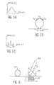
- Figures 5A, 5B and 5C illustrate a Bragg rosette at Sagnac interferometer, operational in transmission, with a source broad spectrum incident optics shown in FIG. 5A, with a coupler represented in FIG. 5B and a spectrum of lines observed in transmission shown in Figure 5C.
- the second advantage of the Sagnac interferometer is in that the fiber micro-system consists of a single fiber plane. he then seems possible to drown the rosette between two layers of a material composite, for example.
- the measurement method can make use an "all-optical” solution (including a transmission filter or a interferometer, providing transmission proportional to the wavelength measured) or optical and electronic (using acquisition by sampling and data processing by dedicated specialized processor).
- the fibers used may or may not be maintenance of polarization.
- the birefringences of constraints induce a poorly defined state of polarization and a measure of less precise constraints than if the fibers have polarization maintenance as noted by T. Valis et al.
- the realization of the rosette is divided into two parts: the registration part of the Bragg networks and the incorporation part on, or within, a support material.
- Bragg network registration methods are described in numerous patents and publications (two-way interferometry methods waves, masking by planar network, fiber travel under a slit, ...); in particularly patent WO 86/01303 by W.H. Glenn, G. Meltz and E. Snitzer.
- the fiber intended to be exposed is stripped of its coating (in the case where it consists of epoxy-acrylate: in the immersed in dichloromethane, for example).
- FIG. 6 illustrates an interferometric arrangement for registering Bragg gratings photo-registered according to the so-called "prism" method, with a photosensitive fiber 20, a prism (at right angles) 21 on which a beam arrives ultraviolet sunshine (low divergence) 22, with a representation of interference fringes 23.
- the angle of incidence on the face of the prism is related to the reflection wavelength of the grating by the following relation: where n p is the prism index at the insolation wavelength ( ⁇ UV ) and N is the effective index of the guided mode (at the Bragg wavelength ( ⁇ B )) already defined in the relation (1).
- the sunshine beam is split into three beams along three prisms oriented along angular angles slightly different, either by turning successively with precision (turntable) the same prism from an appropriate angle, the three Bragg gratings of light characteristic wavelength differences (a few nm, for example) are exposed, simultaneously in the case of the first process and sequentially in the second case.
- the exposed area is large (a few mm long typically 100 ⁇ m wide) so that the constraints of positioning of the fiber on the insulating support are not limiting.
- the size of the rosette is a function of the radius of curvature of the fibers.
- a rosette 2 cm wide by 5 cm long is easily achievable and it seems possible to make a rosette of smaller dimensions (6x9 mm 2 ) according to the publication by HW Haslasch and JS Sirkis (Appl. Opt., Vol. 30 , No. 28, 1991, pages 4069-4080).
- the rosette After exposure, the rosette must be able to be handled without risk of deterioration while retaining precise directions of sunshine.
- the fibers are then bonded to a flexible support. It is also possible to drown the pre-positioned rosette in a polymerizing liquid in order to solidify the assembly and make it easy to handle in an industrial situation.
- FIG. 7 illustrates an example of a rosette support with three gauges for positioning the fiber to be exposed, with a flexible support 24, a silica optical fiber 25, positioning supports 26, networks of Bragg photo-inscribed 27, with traction support 28.
- the rosette can be interrogated in various ways: temporal, frequency or coherent interrogation. These solutions are however little used in practice due to the complexity of detection electronics and the solution is rather to use the wavelength optical multiplexing.
- wavelength interrogation has already been describes: either the sensor is passive, then it just sends back a signal optical (narrow spectrum) in reflection, either the sensor is active and then it re-emits its own radiation after being stimulated by an optical beam question mark.
- active sensor corresponds to a design of laser sensor in which the stresses modify the feedback condition (most often spectrally) of a fiber laser in particular.
- Such device is described in certain publications including the recent publication of S. Melle et al. (IEEE Phot. Tech. Lett., Vol. 5, 1993, pages 263-266).
- a passive sensor i.e. a wide spectral source (superluminescent diode), or a tunable laser (of spectral width lower than that of the network) serve as interrogation optical beam.
- a passive sensor i.e. a wide spectral source (superluminescent diode), or a tunable laser (of spectral width lower than that of the network) serve as interrogation optical beam.
- the rapid detection most often uses a Fabry-Perot interferometer tunable but other solutions can also be used (interferometer by Mach-Zehnder, ..).
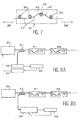
- Figures 8A and 8B Two examples of optical multiplexing circuits are illustrated in Figures 8A and 8B. These figures describe a network of sensors Bragg rosettes questioned in reflection and the processing of the associated signal, respectively for an interrogation wavelength modulation (figure 8A) and for modulation in reading wavelength (“scanning”) (figure 8B).
- FIG. 8A shows a modular optical source in wavelength 30, connected to an optical coupler 31, in optical fibers of which a branch is connected to a photodetector 32 followed by an acquisition module 33 and a modulator 34, itself connected to the source 31.
- Each rosette is composed of three gauges J1, J2 and J3.
- a broad spectral band optical source 36 is connected to an optical coupler 37 made of optical fibers, the second branch of which is connected to a tunable Fabry-Perot interferometer 38 and to a module 39. Also shown in this figure are the rosettes R1 and R2 and the gauges J1, J2 and J3.
- demultiplexing techniques can also be extended to enslavement processes enabling "tracking" in real time the spectral displacements of the Bragg gratings as shown by A.D. Kersey, T.A. Berkoff and W.W. Morey (Opt. Lett., Vol. 18, n ° 16, 1993, pages 1370-1372).
- the circuit has as many rosettes as points of measured.
- Figures 8A and 8B show two rosettes by way of example.
- the rosette defined in the invention can exploit a phenomenon phase agreement physics (Bragg gratings) but also interferometry at two waves (Michelson and Mach-Zehnder) and multiple waves (Fabry-Perot).
- the rosettes composed of interferometric sensors are subject to the same problems of cross-sensitivity to constraints and temperature.
- the optical rosette device of the invention can exploit Bragg gratings or interferometers.
- the interferometric transducers provide information in the form of an optical phase shift.
- the interferometer then aims to translate this phase variation into a intensity variation and it is this variation in intensity which is actually observed in order to deduce the phase variation, the law of phase to intensity conversion being known and dependent on the type of interferometer.
- optical rosette therefore requires the use of a optical source with a coherence length greater than the path difference optical characteristic of the interferometer (typically of the order of a few nm a few cm).
- the most used optical sources are then diodes laser by virtue of their sufficient temporal coherence and their integrability compatible with fiber optic sensor applications.
- ⁇ L x t . dT + x ⁇ .d ⁇ + x p .dP
- L is the difference in length between the reference arm and the measurement arm for the Mach-Zehnder and Michelson interferometers or the length of the resonant cavity in the case of the Fabry-Perot interferometer. This length corresponds to the geometric path imbalance.
- the rosettes are designed differently and the resulting law of intensity is specific.
- This rosette is designed to determine a stress longitudinal only.
- the principle is to choose a configuration geometric as shown in Figure 9A so that the difference in optical paths is proportional to the stress applied along the X axis of the figure.
- the two bundles emerging from the two fibers (measuring and reference) are projected on a screen as shown in FIG. 9B, so to analyze the interference pattern (principle of Young's slits, the hearts of two fibers playing the role of slits).
- Figure 9A illustrates a Mach-Zehnder interferometer gauge for the measurement of a longitudinal stress (after Sirkis and Taylor): respectively the constitution and the experimental set-up.
- Figure 9B illustrates a rosette with Mach-Zehnder interferometers.
- FIG. 9A there is a measurement fiber 40 and a measurement fiber. reference 41 pasted in a circle.
- FIG. 9B there is a screen 42, a beam 43, a separating slide 44, microscope objectives 45, mirrors 46 and a laser 47.
- Interferometry is performed between each optical beam of measurement reflected in the three measurement arms with the reflected signal from of the reference arm (not subject to the constraints to be determined).
- phase shift ⁇ induced by the constraints and the temperature can be chosen low (less than ⁇ ) so that the evolution of the intensity is carried out on the side of the transfer curve of the interferometer of Michelson and Mach-Zehnder, as shown in Figure 10 which illustrates an intensity curve as a function of the optical delay R (phase shift), with a two wave interferometer.
- the difference in length between the measuring arm and the reference arm should be of the order of a few mm to a few cm.
- i 1 or 2 or 3 depending on the measurement arm questioned and m is the contrast (visibility) of the fringes.
- m is an experimental parameter (positive and less than 1) which depends on the respective intensities of the reference beam and the measurement beam established during the construction of the rosette.
- I i is the intensity observed as a function of the phase shift ⁇ i (projected on the screen in the case of FIG. 9B) and I oi is the laser intensity injected.
- the intensity observed is directly converted into current by a measuring photodiode, the current of which can be measured by a pico-ammeter or by an amplifier (phototransistor circuit) as described in the publication by Sirkis and Taylor.
- the sensitivity of the gauges is maximum at a point of operating at mid-height (see Figure 10); it is however difficult to adjust the operating point simultaneously for the three gauges (in changing the wavelength), hence the need for a compromise.
- a solution developed by the CSO Company in France then consists in splitting the measurement beam into two, one observed directly, the other crossing an optical path corresponding to a quarter wave phase shift.
- two interference functions are observed in quadrature, which makes it possible to lift the indeterminacy concerning the sign of the applied stress.
- the networking of several rosettes is done by repeating the motif illustrated in FIG. 11, by placing several 1x4 couplers (50) in series, or by associating as many lasers 51 as rosettes 52.
- mirrors can be advantageously made by photo-registered Bragg gratings of lengths characteristic wavelength covering the wavelength of the laser used.
- the induced phase variation (by pressure, temperature or stress) produces a variation in intensity transmitted according to the well-known Airy function, represented in FIG. 12.
- I 0 is the incident intensity (coming from the diode).
- R 1 and R 2 are the reflection coefficients of the semi-reflective solder and of the dielectric layer.
- the intensity observed in reflection corresponds to the complement of the intensity I 0 of the formula (12).
- optical connection is illustrated in Figure 13, with a optical source (laser diode) 60, 1x3 coupler (61), rosette 62, fibers 63, semi-reflective solders 64, photodiodes 65 and 1x2 optical couplers (66).
- laser diode laser diode
- 1x3 coupler 61
- rosette 62 fibers 63
- semi-reflective solders 64 64
- photodiodes 65 photodiodes
- 1x2 optical couplers 66
Landscapes
- Physics & Mathematics (AREA)
- General Physics & Mathematics (AREA)
- Length Measuring Devices By Optical Means (AREA)
- Optical Transform (AREA)
Description
La présente invention concerne un micro-système optique de type rosette de jauges de contraintes à guides diélectriques, pour la mesure d'une contrainte longitudinale. Dans la suite de la description, l'expression contrainte longitudinale sera utilisée pour désigner une contrainte n'ayant qu'une seule composante.The present invention relates to an optical microsystem of rosette type of strain gauges with dielectric guides, for measurement of a longitudinal constraint. In the following description, the expression longitudinal constraint will be used to designate a constraint having only one single component.
Actuellement, les mesures d'allongement sont réalisées par des jauges ou des rosettes (c'est-à-dire une structure assemblée de plusieurs jauges) à pistes métalliques ou composées de semi-conducteurs, comme représenté sur la figure 2A.Currently, the elongation measurements are carried out by gauges or rosettes (i.e. an assembled structure of several gauges) with metal or semiconductor tracks, such as shown in Figure 2A.
Une jauge mesure une composante d'orientation connue, tandis qu'une rosette permet de déterminer les valeurs des contraintes principales du plan des jauges, ainsi que l'orientation du repère principal par rapport à la disposition des jauges constituant la rosette.A gauge measures a known orientation component, while a rosette makes it possible to determine the values of the stresses the main plane of the gauges, as well as the orientation of the main reference by relation to the arrangement of the gauges constituting the rosette.
Ces jauges ou ces rosettes sont donc électriques et compensées en température sur un domaine restreint d'utilisation, par un choix judicieux de matériaux.These gauges or rosettes are therefore electric and temperature compensated in a restricted area of use, by a choice judicious materials.
Face à cela, de nouvelles techniques d'extensométrie apparurent ces dernières années du fait des progrès de l'optoélectronique. Ces techniques reposent sur des phénomènes optiques et non plus électriques : capteurs polarimétriques, à couplage de modes ou interférométriques.Faced with this, new extensometry techniques appeared in recent years due to advances in optoelectronics. These techniques are based on optical rather than electrical phenomena: polarimetric, mode coupled or interferometric sensors.
Ces capteurs, comme la plupart des capteurs existants, présentent toutefois une sensibilité à la température qui n'est pas compensée de façon intrinsèque. La solution usuellement préconisée à ce type de problème consiste à comparer la réponse d'un détecteur soumis à la contrainte à déterminer (et donc, à la déformation induite) à la réponse d'un autre détecteur de référence, non soumis à cette contrainte. Le comportement du capteur formé des deux détecteurs devient indépendant des fluctuations de température si ces derniers sont suffisamment proches pour être effectivement à la même température. Dans la plupart des cas, les deux détecteurs sont placés relativement loin l'un par rapport à l'autre pour des raisons de construction mécanique, de sorte que cette hypothèse n'est pas toujours vérifiée en ambiance industrielle.These sensors, like most existing sensors, have a temperature sensitivity which is not compensated for by intrinsically. The solution usually recommended for this type of problem is to compare the response of a stressed detector to determine (and therefore, the induced deformation) to the response of another detector of reference, not subject to this constraint. The behavior of the trained sensor of the two detectors becomes independent of temperature fluctuations if these last are close enough to actually be at the same temperature. In most cases, both detectors are placed relatively far from each other for construction reasons mechanical, so this hypothesis is not always verified in industrial atmosphere.
Un exemple d'une telle impossibilité technique peut être, par exemple, la mesure d'une contrainte appliquée sur une nervure ou un longeron d'une aile d'avion en matériau composite. Dans un tel cas, sachant que les détecteurs sont noyés dans le composite, il faut donc les isoler spatialement afin que l'un mesure une contrainte et que l'autre n'y soit pas soumis. Or, il n'est pas concevable de placer un capteur de contraintes loin de son capteur de référence en température car les écarts de température peuvent être trop importants.An example of such a technical impossibility may be, for example example, the measurement of a stress applied to a rib or a spar of an airplane wing made of composite material. In such a case, knowing that the detectors are embedded in the composite, so we must isolate them spatially so that one measures a constraint and that the other is not subjected to it. However, it is not conceivable to place a stress sensor far from its reference sensor in temperature because the temperature differences may be too great.
Cette sensibilité croisée (à la température et aux contraintes) limite actuellement l'essor industriel des capteurs à fibres optiques, notamment pour la mesure de contraintes. Une solution technologique à ce problème est donc d'une importance primordiale afin de supprimer ce point de blocage et d'imposer ce nouveau domaine d'instrumentation.This cross sensitivity (to temperature and constraints) is currently limiting the industrial development of fiber optic sensors, in particular for stress measurement. A technological solution to this problem is therefore of paramount importance in order to remove this blocking point and to impose this new field of instrumentation.
Ce problème de sensibilité croisée n'est pas encore résolu d'une façon satisfaisante (voir, en particulier, l'article récent de E.J. Friebele et A.D. Kersey paru dans Laser Focus World, mai 1994, pages 165-171). Certaines solutions alternatives ont été brevetées qui consistent à compenser la dilatation en température du détecteur (brevet W.W. Morey et W.L. Glomb, WO 91/10151). Le principe revient à incorporer la fibre sensible entre deux pièces constituées de matériaux différents (et donc de coefficients de dilatation thermique différents). Ces auteurs montrent alors qu'il est possible de trouver une constitution géométrique pour laquelle la dilatation résultante appliquée à la fibre de mesure soit nulle. Le problème réside dans le fait que ce système est d'une construction mécanique complexe et nécessite de bien définir les dimensions ainsi que les coefficients de dilatation des matériaux utilisés, de sorte que, dans la pratique, il subsiste toujours une fluctuation en température due aux tolérances de fabrication. This cross-sensitivity problem has not yet been resolved satisfactorily (see, in particular, the recent article by E.J. Friebele and A.D. Kersey published in Laser Focus World, May 1994, pages 165-171). Some alternative solutions have been patented which consist in compensating for expansion in detector temperature (W.W. Morey and W.L. Glomb patent, WO 91/10151). The principle is to incorporate sensitive fiber between two pieces made of different materials (and therefore expansion coefficients different thermal). These authors then show that it is possible to find a geometric constitution for which the resulting expansion applied to the measurement fiber is zero. The problem is that this system is of a complex mechanical construction and requires to define well the dimensions as well as the expansion coefficients of the materials used, of so that in practice there is always a fluctuation in temperature due to manufacturing tolerances.
D'autres idées ont été énoncées, comme utiliser les deux modes de polarisation se propageant dans la fibre (soumis toux deux à des réponses en température et contraintes différentes), ou bien encore, utiliser deux détecteurs de réponses spectrales différentes (article de E.J. Friebele et A.D. Kersey).Other ideas have been stated, such as using the two modes of polarization propagating in the fiber (subject to two responses in different temperatures and constraints), or alternatively, use two detectors of different spectral responses (article by E.J. Friebele and A.D. Kersey).
La limitation vient du fait que les détecteurs présentent des réponses en température et en contraintes très proches car les matériaux mis en oeuvre diffèrent très peu. Une distinction très résolue est donc difficile. De plus, la première solution impose de maintenir la polarisation de la lumière (fibre à maintien de polarisation), ce qui complique considérablement la mise en oeuvre d'un tel dispositif de mesure (connectique complexe) et augmente conjointement son coût.The limitation comes from the fact that the detectors have very similar temperature and stress responses because the materials used works differ very little. A very resolute distinction is therefore difficult. In addition, the first solution requires maintaining the polarization of light (fiber to polarization maintenance), which considerably complicates the implementation of such a measurement device (complex connectivity) and jointly increases its cost.
L'objet de l'invention est de proposer un dispositif permettant de s'affranchir rigoureusement des fluctuations de température d'une façon mathématique, via une procédure de traitement des informations recueillies à partir d'un capteur comprenant des détecteurs placés suffisamment proches les uns des autres pour être à la même température.The object of the invention is to propose a device making it possible to rigorously overcome temperature fluctuations in a way mathematical, via a procedure for processing the information collected at from a sensor comprising detectors placed close enough to the each other to be at the same temperature.
La présente invention concerne un micro-système optique de
type rosette de jauges de contraintes à guides diélectriques, destiné à mesurer
un ensemble de contraintes appliquées à une pièce, ledit micro-système
comprenant au moins une rosette formée d'au moins deux jauges de contraintes
à guides diélectriques (J1, J2, J3) d'orientations connues et non parallèles,
caractérisé en ce que les jauges de contrainte sont des réseaux de Bragg (RB1,
RB2, RB3), en ce que la pièce est une pièce soumise à une contrainte d'une seule
composante contenue dans le plan des jauges, et en ce qu'un circuit de calcul,
qui délivre un résultat indépendant de la température, permet de déterminer ladite
contrainte par résolution du système d'équations suivant :
Ainsi selon l'invention, une rosette de jauges de contraintes à guides diélectriques, à fibres optiques notamment, de principe connu, destinée habituellement à mesurer le système de contraintes, d'orientation inconnue a priori, appliqué à une pièce en un point, est utilisé, de manière surprenante, dans le cas d'une pièce soumise à une contrainte n'ayant qu'une composante. La solution d'un système d'équations par un circuit de calcul permet de déterminer la contrainte, indépendamment de la température, si la rosette est formée de deux jauges à fibres optiques de l'angle de positionnement de la rosette sur la pièce si elle est formée de trois jauges. Ce principe est valable pour toutes jauges mesurant une variation de chemin optique sous contrainte, en particulier aux réseaux de Bragg photo-inscrits.Thus according to the invention, a rosette of strain gauges to dielectric guides, in particular with optical fibers, of known principle, intended usually to measure the constraint system, of unknown orientation a a priori, applied to a part at a point, is used, surprisingly, in the case of a part subjected to a constraint having only one component. The solution of a system of equations by a calculation circuit allows to determine the constraint, regardless of temperature, if the rosette is formed of two fiber optic angle gauges positioning of the rosette on the part if it is formed by three gauges. This principle is valid for all gauges measuring a variation of optical path under constraint, in particular to photo-registered Bragg networks.
Avantageusement la rosette est formée de trois réseaux de Bragg placés à 120° ou à 45° les uns des autres. Ces trois réseaux peuvent être inscrits simultanément ou successivement par le même faisceau optique d'insolation. Ces trois réseaux peuvent ne pas être inscrits simultanément et peuvent présenter des longueurs d'onde caractéristiques différentes.Advantageously, the rosette is formed of three networks of Bragg placed at 120 ° or 45 ° from each other. These three networks can be registered simultaneously or successively by the same optical beam sunstroke. These three networks may not be registered simultaneously and may have different characteristic wavelengths.
Avantageusement les guides diélectriques sont des fibres optiques.Advantageously the dielectric guides are optical fibers.
Ce micro-système optique comprend au moins un guide diélectrique, à maintien ou non de polarisation, dans lequel sont incorporées les jauges de contraintes qui sont des transducteurs d'allongement, disposés suivant des orientations connues non parallèles. Les transducteurs d'allongement, qui sont eux-mêmes des guides diélectriques, peuvent être collés en surface, ou noyés au sein d'un matériau support localement plan dont les déformations sont à déterminer.This optical micro-system includes at least one guide dielectric, maintaining or not polarizing, in which are incorporated the strain gauges which are elongation transducers, arranged following known non-parallel orientations. Transducers elongation, which are themselves dielectric guides, can be bonded to the surface, or embedded in a locally planar support material of which the deformations are to be determined.
Dans un exemple de réalisation ces transducteurs sont des réseaux de Bragg qui fonctionnent par effet d'accord de phase et les guides sont monomodes et photosensibles (par exemple matrice germanosilicate ou dopée par des ions de terres rares (Ce3+, ...)).In an exemplary embodiment these transducers are Bragg gratings which operate by phase tuning effect and the guides are monomode and photosensitive (for example germanosilicate matrix or doped with rare earth ions (Ce 3+ , ...) ).
Dans un autre exemple de réalisation les transducteurs fonctionnent par effet interférométrique (interféromètres de Fabry-Perot, Michelson ou Mach-Zehnder) et les guides sont monomodes.In another exemplary embodiment the transducers operate by interferometric effect (Fabry-Perot interferometers, Michelson or Mach-Zehnder) and the guides are single-mode.
Dans un exemple de réalisation chaque jauge mesure une variation de chemin optique fonction de la contrainte à mesurer, qui induit un décalage spectral (réseau de Bragg).In an exemplary embodiment each gauge measures a variation of optical path as a function of the stress to be measured, which induces a spectral shift (Bragg grating).
Dans un autre exemple de réalisation chaque jauge mesure une variation du chemin optique fonction de la contrainte à mesurer qui induit un décalage de franges d'interférences (interféromètres de Fabry-Perot, Michelson, Mach-Zehnder).In another example of embodiment, each gauge measures a variation of the optical path as a function of the stress to be measured which induces a interference fringe shift (Fabry-Perot, Michelson interferometers, Mach-Zehnder).
Le micro-système optique de l'invention peut être tel que les jauges constituant la rosette sont placées en série sur le même guide diélectrique.The optical micro-system of the invention can be such that the gauges constituting the rosette are placed in series on the same guide dielectric.
Le microsystème peut également présenter une configuration du type interféromètre de Sagnac équilibré exploitant un coupleur à 50 % de réflexion dans la bande spectrale d'utilisation, cette configuration étant constituée d'un seul plan de guide et permettant d'inclure une rosette entre deux plans d'un matériau.The microsystem can also present a configuration of the balanced Sagnac interferometer type using a coupler at 50% reflection in the spectral band of use, this configuration being consisting of a single guide plane and allowing the inclusion of a rosette between two plans of a material.
Le présent micro-système permet ainsi de fournir un signal optique permettant de mesurer une contrainte longitudinale pure (traction, compression), et ceci indépendamment de la température et du positionnement de ce micro-système optique sur le matériau support dont les contraintes sont à déterminer. Le capteur de contraintes longitudinales ainsi formé est donc parfaitement adapté à une ambiance industrielle (chantier, ...) car il n'a plus besoin de procédure de correction en température et peut être disposé arbitrairement dans n'importe quelle position sur une partie plane de la pièce à surveiller (poutre, mât, panneau, ...). Une application particulièrement intéressante consiste à insérer la fibre sensible au sein d'un matériau de type composite. La fibre peut avantageusement rentrer en substitution de plusieurs fibres de renfort (en carbone, typiquement) et conserve l'alignement de ces fibres. Les fibres composant la rosette sont placées au sein de plans parallèles d'orientations différentes. Une telle rosette peut être insérée dans une nervure ou un longeron d'une aile d'avion en composite et l'information de contrainte longitudinale peut être retrouvée quelle que soit l'orientation connue (non-parallèle) des deux ou trois jauges composant cette rosette.The present micro-system thus makes it possible to provide a signal optics for measuring a pure longitudinal stress (traction, compression), regardless of temperature and positioning of this optical micro-system on the support material whose constraints are determine. The longitudinal stress sensor thus formed is therefore perfectly suited to an industrial environment (construction site, ...) because it no longer has need temperature correction procedure and can be arranged arbitrarily in any position on a flat part of the part to monitor (beam, mast, panel, ...). A particularly application interesting is to insert the sensitive fiber within a material of the type composite. The fiber can advantageously enter in substitution for several reinforcing fibers (carbon, typically) and keeps the alignment of these fibers. The fibers making up the rosette are placed within parallel planes of different orientations. Such a rosette can be inserted into a rib or a spar of a composite airplane wing and the stress information longitudinal can be found regardless of the known orientation (non-parallel) two or three gauges making up this rosette.
L'information de contrainte peut être traduite optiquement de diverses façons car le micro-système peut exploiter différents principes physiques de détection (interférométrie, accord de phase) dans la mesure où tous ces principes font intervenir le guide diélectrique comme capteur intrinsèque, guide dont l'indice effectif de guidage et la longueur d'interaction dépendent tous deux de la température, en plus des contraintes.Constraint information can be translated optically from various ways because the micro-system can exploit different principles physical detection (interferometry, phase agreement) insofar as all these principles involve the dielectric guide as a sensor intrinsic, guide whose effective guide index and interaction length both depend on temperature, in addition to constraints.
- Les figures 1A, 1B, 1C et 1D illustrent le comportement de filtrage des réseaux de Bragg photo-inscrits ;Figures 1A, 1B, 1C and 1D illustrate the behavior of filtering of photo-registered Bragg networks;
- les figures 2A, 2B et 2C sont des exemples types de rosettes de jauges de contraintes connues ;Figures 2A, 2B and 2C are typical examples of rosettes gauges of known constraints;
- les figures 3A, 3B et 3C sont des exemples de configuration de rosettes à trois réseaux de Bragg selon l'invention ;Figures 3A, 3B and 3C are configuration examples rosettes with three Bragg gratings according to the invention;
- la figure 4 illustre la configuration des spectres optiques en fonction de la longueur d'onde ;FIG. 4 illustrates the configuration of the optical spectra in wavelength function;
- les figures 5A, 5B et 5C illustrent une rosette de Bragg à interféromètre de Sagnac ;FIGS. 5A, 5B and 5C illustrate a Bragg rosette at Sagnac interferometer;
- la figure 6 illustre un montage interférométrique d'inscription de réseaux de Bragg photo-inscrits selon la méthode dite "du prisme" ;FIG. 6 illustrates an interferometric registration arrangement Bragg gratings photo-registered according to the so-called "prism" method;
- la figure 7 illustre un exemple de support de rosette à trois jauges ;FIG. 7 illustrates an example of a rosette support with three gauges;
- les figures 8A et 8B illustrent un réseau de capteurs à rosettes de Bragg ;Figures 8A and 8B illustrate a network of sensors to Bragg rosettes;
- la figure 9A illustre une jauge à interféromètre de Mach-Zehnder pour la mesure d'une contrainte longitudinale ;Figure 9A illustrates a Mach-Zehnder interferometer gauge for the measurement of a longitudinal stress;
- la figure 9B illustre une rosette à interféromètre de Mach-Zehnder pour la mesure d'une contrainte longitudinale ; FIG. 9B illustrates a rosette with a Mach-Zehnder interferometer for the measurement of a longitudinal stress;
- la figure 10 illustre une fonction de transfert des interféromètres de Michelson et de Mach-Zehnder;FIG. 10 illustrates a function for transferring Michelson and Mach-Zehnder interferometers;
- la figure 11 illustre une rosette à interféromètre de Michelson ;FIG. 11 illustrates a rosette with a Michelson interferometer;
- la figure 12 illustre les fonctions de transfert typiques d'un interféromètre de Fabry-Perot pour plusieurs coefficients de réflexion ;Figure 12 illustrates the typical transfer functions of a Fabry-Perot interferometer for several reflection coefficients;
- la figure 13 illustre une rosette à interféromètres de Fabry-Perot.FIG. 13 illustrates a rosette with Fabry-Perot interferometers.
Pour mieux décrire le dispositif de l'invention, on va tout d'abord faire quelques rappels concernant les réseaux de Bragg photo-induits.To better describe the device of the invention, we will first make some reminders concerning the photo-induced Bragg gratings.
Le principe des réseaux de Bragg fonctionnant en jauges de contraintes consiste à utiliser la dépendance du spectre de réflexion ou de transmission de ce type de transducteur soumis à une contrainte locale (de traction ou de compression) orientée suivant l'axe d'une fibre. Le réseau ne transmet que la contrainte orientée suivant l'axe local de la fibre.The principle of Bragg gratings operating in gauges of constraints is to use the dependence of the reflection spectrum or transmission of this type of transducer subject to local stress (of traction or compression) oriented along the axis of a fiber. The network does transmits that the stress oriented along the local axis of the fiber.
Comme représenté sur la figure 1A, le réseau de Bragg filtre la
lumière en réflexion, les ondes (incidentes et réfléchies) restant guidées. La
longueur d'onde filtrée (en réflexion) est celle qui correspond à l'accord de phase
(condition de Bragg) :
Ainsi les figures 1B à 1D illustrent le comportement de filtrage de trois réseaux de Bragg photo-inscrits RB1, RB2 et RB3 représentés en figure 1A.Thus Figures 1B to 1D illustrate the filtering behavior of three photo-registered Bragg gratings RB1, RB2 and RB3 shown in figure 1A.
Les figures 1B, 1C et 1D sont des courbes de l'intensité en fonction de la longueur d'onde, respectivement du spectre incident, du spectre transmis et du Spectre réfléchi.Figures 1B, 1C and 1D are curves of the intensity in function of the wavelength, respectively of the incident spectrum, of the spectrum transmitted and reflected Spectrum.
Les fibres optiques sont, le plus souvent, monomodes afin que toute l'énergie qui se propage dans un seul mode soit presque intégralement réfléchie à la longueur d'onde d'accord (réflexion supérieure à 95 %). Dans le cas où la fibre est multimode, l'accord en longueur d'onde est différent pour chaque mode.Optical fibers are most often single-mode so that all the energy that propagates in a single mode is almost entirely reflected at the tuning wavelength (reflection greater than 95%). In the where the fiber is multimode, the wavelength tuning is different for each mode.
Ces fibres sont, le plus souvent, à coeur de silice codopé avec de l'oxyde de germanium mais un codopage avec de l'alumine ou des oxydes de terres rares (cérium) a également été publié. La diffusion d'hydrogène ou de deutérium dans le coeur permet également d'accroítre la photosensibilité des fibres silice. D'autres verres, de type verres fluorés codopés avec des oxydes de terres rares, par exemple, permettent également de réaliser des réseaux de Bragg photo-inscrits.These fibers are, most often, with a silica core codoped with germanium oxide but codoping with alumina or oxides of rare earths (cerium) has also been published. Diffusion of hydrogen or deuterium in the heart also increases the photosensitivity of silica fibers. Other glasses, such as fluorinated glasses codoped with oxides of rare earths, for example, also allow networks of Bragg photo-enrolled.
L'insolation modifie l'indice local de réfraction de sorte qu'une insolation spatialement périodique crée le réseau, soit par insolation inteme (ondes stationnaires internes au guide), soit par insolation externe (franges d'interférences à deux ondes). L'insolation externe permet d'inscrire un réseau de n'importe quelle période spatiale tandis que l'insolation interne ne permet d'inscrire qu'un réseau de même période que la demi-longueur d'onde d'insolation.The exposure changes the local index of refraction so that a spatially periodic insolation creates the network, either by internal insolation (standing waves internal to the guide), or by external insolation (fringes two-wave interference). External insolation allows to register a network of any spatial period while internal insolation does not allow to record that a network of the same period as the half wavelength sunstroke.
Les méthodes d'inscription ont été décrites par de nombreux brevets et publications. La méthode d'inscription externe par interférométrie à deux ondes - la plus utilisée- est décrite dans le brevet WO 86/01303 déposé par W.H. Glenn, G. Meltz et E. Snitzer.Registration methods have been described by many patents and publications. The external registration method by interferometry at two waves - the most used - is described in patent WO 86/01303 filed by W.H. Glenn, G. Meltz and E. Snitzer.
Les transducteurs optiques fondés sur l'emploi de réseaux de Bragg dispensent de multiples avantages : ils sont insensibles aux perturbations électromagnétiques, autorisent le multiplexage (par exemple : en longueur d'onde, dans le cas qui nous préoccupe), sont de dimensions millimétriques (approche micro-système) et conduisent à des résolutions et sensibilités de mesure comparables aux méthodes classiques telles que les jauges de contraintes résistives à fils métalliques ou à semi-conducteurs.Optical transducers based on the use of Bragg provide multiple advantages: they are insensitive to disturbances electromagnetic, allow multiplexing (for example: in length (in the case which concerns us), are of millimeter dimensions (micro-system approach) and lead to resolutions and sensitivities of measurement comparable to conventional methods such as gauges resistive stresses on metallic or semiconductor wires.
Les capteurs exploitant le principe de la dépendance de la longueur d'onde d'accord du réseau de Bragg en fonction de l'allongement dudit réseau (consécutif à une contrainte) sont également dépendants de la température via le coefficient de dilatation de la matrice (silice le plus souvent) et de la sensibilité thermique de son indice de réfraction. Dans la plupart des applications réelles (hors laboratoire), la température n'est pas contrôlée et il est facilement prouvé que l'allongement dû à la dilatation thermique ne peut être négligé au regard des allongements induits par contrainte que l'on cherche à mesurer.The sensors exploiting the principle of dependence of the tuning wavelength of the Bragg grating as a function of the elongation of said network (following a constraint) are also dependent on the temperature via the coefficient of expansion of the matrix (silica most often) and the thermal sensitivity of its refractive index. In most real applications (except laboratory), the temperature is not controlled and it is easily proven that the elongation due to thermal expansion cannot be neglected in view of the stress-induced elongations that one seeks to measure.
Le concept de rosette n'est pas nouveau et les rosettes sont utilisées depuis longtemps pour déterminer les valeurs des deux contraintes principales du plan ainsi que la direction du repère principal, si la température T est connue. Le principe d'une rosette de jauges de contraintes à fibres optiques a été décrit dans une publication récente de T. Valis, D. Hogg et R.M. Measures (Smart Mater. Struct., vol. 1, 1992, pages 227-232). Cette rosette utilise soit des interféromètres de Fabry-Perot, soit des interféromètres de Michelson comme jauges de contraintes comme représenté sur les figures 2B et 2C.The concept of rosette is not new and rosettes are long used to determine the values of the two constraints principal of the plane as well as the direction of the principal reference mark, if the temperature T is known. The principle of a rosette of fiber optic strain gauges was described in a recent publication by T. Valis, D. Hogg and R.M. Measures (Smart Mater. Struct., Vol. 1, 1992, pages 227-232). This rosette uses either Fabry-Perot interferometers, or Michelson interferometers like strain gauges as shown in Figures 2B and 2C.
Les figures 2A, 2B et 2C sont en effet des exemples types de
rosettes de jauges de contraintes permettant de mesurer les deux contraintes
principales du plan des jauges ainsi que l'orientation de leur repère principal ; la
figure 2A représente une rosette classique (électrique) à pistes métalliques 10 ;
la figure 2B représente une rosette optique à interféromètres de Michelson avec
des bras de mesure 11 et un bras de référence 12; la figure 2C représente une
rosette optique à interféromètres de Fabry-Perot (de cavité formée d'une couche
diélectrique 68 déposée en bout de fibre et d'une soudure semi-réflectrice
13). Dans ces deux dernières figures la largeur e est égale à 125 µm par
exemple, et la longueur 14 est la longueur sensible.Figures 2A, 2B and 2C are indeed typical examples of
rosettes of strain gauges to measure the two stresses
principal of the plan of the gauges as well as the orientation of their principal reference; the
FIG. 2A represents a conventional (electric) rosette with
Ces rosettes ont été exploitées d'une façon classique, c'est-à-dire pour trouver l'orientation du repère principal des contraintes ainsi que les valeurs des deux contraintes principales du plan, la température des fibres de mesure étant supposée connue (ce qui n'est pas le cas dans la pratique).These rosettes have been exploited in a conventional manner, that is to say to find the orientation of the main constraints coordinate system and the values of the two main stresses of the plane, the temperature of the fibers of measure being assumed to be known (which is not the case in practice).
L'originalité de l'invention réside dans l'exploitation de cette géométrie pour ne mesurer ponctuellement qu'une contrainte mais indépendamment de la température et du positionnement de la rosette dans son plan. Elle est originale en ce sens qu'elle permet de s'affranchir rigoureusement des effets de la température pour ne mesurer que ceux dus aux efforts de traction/compression à déterminer (ce qui est plus performant que les concepts précédemment cités) à la condition que la contrainte soit purement longitudinale dans le cas d'une rosette simple.The originality of the invention lies in the use of this geometry to measure punctually only one constraint but regardless of the temperature and the positioning of the rosette in its plan. It is original in the sense that it allows to rigorously overcome effects of temperature to measure only those due to the efforts of traction / compression to be determined (which is more efficient than the concepts previously cited) on condition that the constraint is purely longitudinal in the case of a single rosette.
L'avantage tient à ce que l'information peut être retrouvée quel que soit le positionnement de la rosette sur la surface ou au sein du matériau support et, qu'en effectuant la mesure ponctuellement, il n'y a plus besoin de deuxième fibre de référence pour s'affranchir de la température. Cette solution résout donc le problème de la sensibilité croisée aux contraintes et à la température dans le cas d'une contrainte longitudinale (nervure, longeron, mat, poutre, ...) et résout le problème de trouver une référence fiable en température.The advantage is that the information can be found whatever either the positioning of the rosette on the surface or within the material support and, that by performing the measurement punctually, there is no longer any need to second reference fiber to overcome temperature. This solution therefore solves the problem of cross-sensitivity to constraints and temperature in the case of a longitudinal stress (rib, spar, mast, beam, ...) and solves the problem of finding a reliable temperature reference.
Bien que ce concept de micro-système soit démontré ici en exploitant des fibres optiques (premier niveau d'intégration), il est réalisable en optique intégrée (deuxième degré d'intégration).Although this concept of micro-system is demonstrated here in using optical fibers (first level of integration), it can be achieved by integrated optics (second degree of integration).
L'invention consiste à mesurer les différences de longueurs d'onde caractéristiques de deux (ou trois) réseaux. Ces réseaux peuvent être placés, a priori, suivant n'importe quelle orientation mais non parallèlement les uns aux autres.The invention consists in measuring the differences in lengths wave characteristics of two (or three) networks. These networks can be placed, a priori, in any orientation but not in parallel to each other.
Si la rosette n'est constituée que de deux réseaux, il est possible d'en déduire la contrainte longitudinale exercée, indépendamment de la température, l'angle de positionnement de cette rosette par rapport à l'orientation de cette contrainte étant supposé connu.If the rosette consists of only two networks, it is possible to deduce the longitudinal stress exerted, regardless of the temperature, the positioning angle of this rosette relative to the orientation of this constraint being assumed to be known.
Si, par contre, la rosette est constituée de trois réseaux, il est possible, cette fois, d'en déduire la contrainte longitudinale exercée, indépendamment de la température et du positionnement (c'est-à-dire de l'angle que fait l'orientation de la rosette par rapport à la direction de la contrainte à déterminer).If, on the other hand, the rosette is made up of three networks, it is possible, this time, to deduce from it the longitudinal stress exerted, regardless of temperature and positioning (i.e. angle what does the orientation of the rosette do with respect to the direction of the stress at determine).
En pratique, ces trois réseaux composant la rosette sont généralement placés précisément soit à 120°, soit à 45° les uns des autres afin de faciliter le dépouillement des résultats par l'emploi de formules mathématiques plus simples.In practice, these three networks making up the rosette are usually placed precisely either at 120 ° or 45 ° from each other so to facilitate the analysis of the results by the use of formulas simpler math.
Les figures 3A, 3B et 3C représentent des exemples de
configuration de rosettes à trois réseaux de Bragg RB1, RB2 et RB3 mesurant
respectivement les déformations ε1,ε2 et ε3 respectivement pour une rosette à
120°, une rosette à 45° et une rosette à 120° à réseaux de Bragg, avec trois
jauges J1, J2 et J3, en utilisant une fibre optique silice 15 (photo-inscriptible).FIGS. 3A, 3B and 3C represent examples of the configuration of rosettes with three Bragg gratings RB 1 , RB 2 and RB 3 measuring respectively the deformations ε 1 , ε 2 and ε 3 respectively for a rosette at 120 °, a rosette with 45 ° and a 120 ° rosette with Bragg gratings, with three gauges J1, J2 and J3, using a
Toutefois, pour des raisons de tolérances de fabrication, les angles de positionnement ne seront pas toujours proches de ces valeurs idéales de sorte que la résolution numérique d'un système d'équations (3) de la rosette défini ci-après sera appliquée. However, for reasons of manufacturing tolerances, positioning angles will not always be close to these ideal values so that the numerical resolution of a system of equations (3) of the rosette defined below will be applied.
Du point de vue de l'interrogation spectrale, plusieurs solutions sont envisageables. On peut en citer deux, à titre d'exemples :
- Les trois réseaux sont inscrits simultanément ou successivement par le même faisceau optique d'insolation (ils possèdent alors la même fonction de transfert, et donc la même longueur d'onde caractéristique) : la mesure du maximum spectral n'est plus possible simplement avec cette technique puisqu'il y a recouvrement des spectres caractéristiques. Dans ce dernier cas, une technique d'interrogation plus complexe est requise, en l'occurrence une interrogation résolue dans le temps, par exemple, comme décrit dans le brevet US-4 996 419 de W.W. Morey.
- Les trois réseaux ne sont pas inscrits simultanément et peuvent présenter des longueurs d'onde caractéristiques différentes : cette solution est plus simple à mettre en oeuvre du point de vue de la mesure et du démultiplexage.
- The three gratings are registered simultaneously or successively by the same insolation optical beam (they then have the same transfer function, and therefore the same characteristic wavelength): the measurement of the spectral maximum is no longer possible simply with this technical since there is overlap of the characteristic spectra. In the latter case, a more complex interrogation technique is required, in this case an interrogation resolved over time, for example, as described in US Pat. No. 4,996,419 to WW Morey.
- The three networks are not registered simultaneously and may have different characteristic wavelengths: this solution is simpler to implement from the point of view of measurement and demultiplexing.
Dans les deux cas, les réseaux doivent être inscrits dans des fibres présentant les mêmes coefficients de dilatation thermique. Cette condition est évidemment réalisée si les fibres sont strictement identiques (issues de la même préforme). Ainsi, si l'on pose comme hypothèse que les transducteurs de Bragg composant la rosette sont suffisamment proches les uns des autres pour être à la même température, la mesure des différences de longueurs d'onde caractéristiques permet de déterminer la contrainte de traction indépendamment de la température.In both cases, the networks must be registered in fibers with the same coefficients of thermal expansion. This condition is obviously performed if the fibers are strictly identical (from the same preform). So, if we assume that the transducers of Bragg making up the rosette are close enough to each other to be at the same temperature, measuring differences in wavelengths characteristics independently determine the tensile stress of the temperature.
Dans ce qui suit, on va étudier cette approche plus en détails.In what follows, we will study this approach in more detail.
λ1,λ2 et λ3 sont les longueurs d'onde caractéristiques
respectives des trois réseaux de Bragg constituant la rosette et λ 0 / 1.λ 0 / 2 et λ 0 / 3 les
longueurs d'onde caractéristiques en l'absence de déformations et à une
température T 0 de référence.λ 1 , λ 2 and λ 3 are the respective characteristic wavelengths of the three Bragg gratings constituting the rosette and
Les variations de longueurs d'onde peuvent s'écrire, pour tous
les réseaux (i = 1, 2 et 3) :
Pour simplifier, les trois longueurs d'onde λ1,λ2 et λ 3 sont considérées comme très proches les unes des autres (à quelques nm de décalage).To simplify, the three wavelengths λ 1 , λ 2 and λ 3 are considered to be very close to each other (a few nm apart).
On obtient alors le système suivant d'équations :
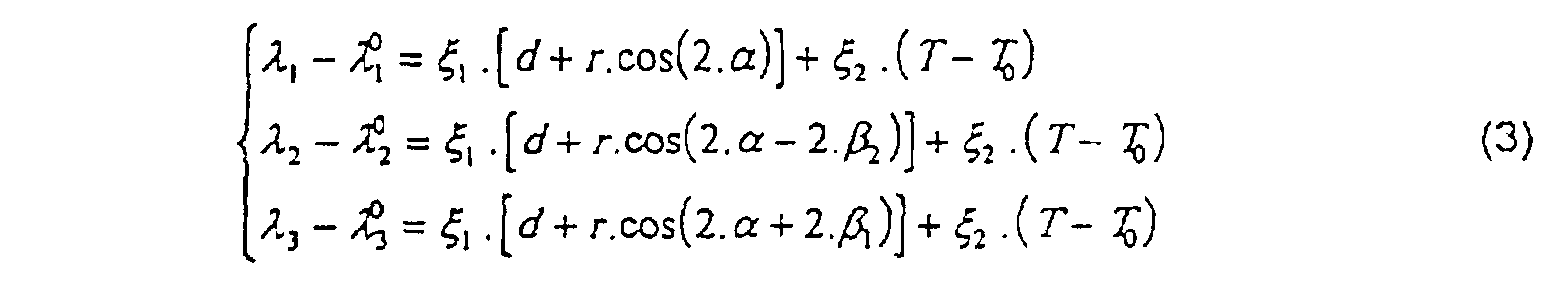
Les deux angles β1 et β2 caractérisant la rosette peuvent être quelconques (mais non nuls modulo π) et α est l'angle que fait l'orientation de la contrainte principale (σ x ) à déterminer avec l'orientation de la jauge de contraintes de référence de la rosette (ici, la jauge J1). Cet angle α est, a priori, inconnu et est fonction des tolérances de positionnement (position de la jauge-rosette sur la surface du matériau support).The two angles β 1 and β 2 characterizing the rosette can be any (but not zero modulo π) and α is the angle made by the orientation of the main stress (σ x ) to be determined with the orientation of the gauge. reference constraints of the rosette (here, the J1 gauge). This angle α is, a priori, unknown and is a function of the positioning tolerances (position of the rosette gauge on the surface of the support material).
Les paramètres d et r sont respectivement la demi-somme et la demi-différence des déformations principales à déterminer.The parameters d and r are respectively the half-sum and the half-difference of the principal strains to be determined.
Si la rosette est construite avec des angles β1 et β2 quelconques mais parfaitement connus après fabrication, il est possible d'en déduire la contrainte principale de traction pure en résolvant numériquement le système (3).If the rosette is constructed with any angles β 1 and β 2 but perfectly known after manufacture, it is possible to deduce therefrom the main stress of pure traction by solving the system numerically (3).
Les équations de déformation permettent de formuler la
contrainte de traction suivant la forme analytique simple :

On appelle f(T)=ξ2 .(T- T 0); si la rosette est construite
précisément suivant un angle à 120°, l'expression de r est donnée par la
formule suivante :
On observe bien que r et α sont indépendants de T, puisque
les deux équations qui les caractérisent sont exprimées en terme de différences
spectrales (écarts de longueurs d'onde entre les sommets des fonctions de
transfert de réseaux de Bragg pris deux-à-deux). Remarquons également que
r et α sont également indépendants de la pression P qui, comme la
température, s'exerce uniformément dans toutes les directions de l'espace. Or,
les deux équations précédentes {(5) et (6)} permettent de formuler la contrainte
directement à partir des longueurs d'onde mesurées, puisque:
La contrainte de traction pure exercée sur le matériau s'écrit
donc finalement, dans le cas de la rosette à trois jauges exactement à 120° :

De la même façon, pour une rosette à trois jauges exactement à
45°:

Si les longueurs d'onde λ1,λ2 et λ3 sont séparées de plus de
quelques nm (mais toujours dans une même bande spectrale de quelques
dizaines de manomètres de large), les équations (7) et (8) doivent être réécrites
en substituant le terme :
Le capteur peut être interrogé optiquement de façon continue ou de façon impulsionnelle, à l'aide d'une source spectralement plus large ou, a contrario, beaucoup plus fine que la largeur spectrale du réseau de Bragg interrogé.The sensor can be continuously optically interrogated or impulsively, using a spectrally wider source or, a contrario, much finer than the spectral width of the Bragg grating interrogates.
Deux conceptions peuvent être retenues :
- Capteur passif: le signal optique mesuré correspond à la réflexion (ou à la transmission) d'un signal d'interrogation à large bande spectrale, voire à spectre fin accordable ;
- Capteur actif : le signal optique mesuré correspond à l'émission du capteur laser interrogé par un signal optique de pompage (à une longueur d'onde différente de l'émission laser).
- Passive sensor: the optical signal measured corresponds to the reflection (or transmission) of an interrogation signal with a broad spectral band, or even with a fine tunable spectrum;
- Active sensor: the measured optical signal corresponds to the emission of the laser sensor interrogated by an optical pumping signal (at a wavelength different from the laser emission).
Dans les deux cas, la méthode de détection optique est identique. Celle-ci consiste à observer les spectres de réflexion, voire de transmission (capteurs passifs), ou de réémission (capteurs actifs -lasers) afin d'en déduire les longueurs d'onde caractéristiques.In both cases, the optical detection method is identical. This consists in observing the spectra of reflection, even of transmission (passive sensors), or re-emission (active sensors -lasers) so deduce the characteristic wavelengths.
La figure 4 illustre une courbe des spectres optiques SO en fonction de la longueur d'onde λ, ce qui permet de définir les différentes longueurs d'ondes caractéristiques. Les déformations différentielles entre chaque réseau peuvent être mesurées directement à partir du spectre optique.FIG. 4 illustrates a curve of the optical spectra SO in function of the wavelength λ, which makes it possible to define the different characteristic wavelengths. Differential deformations between each network can be measured directly from the optical spectrum.
Deux constitutions peuvent être envisagées suivant que le procédé d'interrogation des réseaux fonctionne en réflexion ou en transmission. Le fonctionnement en réflexion est illustré sur les figures 8A et 8B.Two constitutions can be envisaged depending on whether the network interrogation process works in reflection or in transmission. The operation in reflection is illustrated in FIGS. 8A and 8B.
En revanche, il est possible de réaliser une boucle (interféromètre de Sagnac) grâce à un coupleur optique dont le taux de couplage est proche de 50 % de réflexion dans la bande spectrale d'intérêt. Cet interféromètre équilibré (50 %) constitue un "miroir à fibre" selon un fonctionnement décrit par K.O. Hill et al. dans une publication (Electr. Lett., vol. 23, n° 9, 1987, pages 465466). L'interféromètre de Sagnac permet alors d'inverser le fonctionnement de la rosette qui d'en réflexion fonctionne alors en transmission sitôt que la longueur de cohérence de l'onde filtrée excède l'écart spectral entre les deux réseaux extrêmes.However, it is possible to make a loop (Sagnac interferometer) thanks to an optical coupler whose coupling rate is close to 50% reflection in the spectral band of interest. This balanced interferometer (50%) constitutes a "fiber mirror" according to a functioning described by K.O. Hill et al. in a publication (Electr. Lett., vol. 23, No. 9, 1987, pages 465466). The Sagnac interferometer then allows to reverse the functioning of the rosette which in reflection then works by transmission as soon as the coherence length of the filtered wave exceeds the difference spectral between the two extreme networks.
Les figures 5A, 5B et 5C illustrent une rosette de Bragg à interféromètre de Sagnac, opérationnelle en transmission, avec une source optique incidente à spectre large représenté en figure 5A, avec un coupleur représenté en figure 5B et un spectre de raies observé en transmission représenté en figure 5C.Figures 5A, 5B and 5C illustrate a Bragg rosette at Sagnac interferometer, operational in transmission, with a source broad spectrum incident optics shown in FIG. 5A, with a coupler represented in FIG. 5B and a spectrum of lines observed in transmission shown in Figure 5C.
Le deuxième avantage de l'interféromètre de Sagnac réside dans le fait que le micro-système à fibre est constitué d'un seul plan de fibre. Il semble alors possible de noyer la rosette entre deux couches d'un matériau composite, par exemple.The second advantage of the Sagnac interferometer is in that the fiber micro-system consists of a single fiber plane. he then seems possible to drown the rosette between two layers of a material composite, for example.
D'un point de vue pratique, la méthode de mesure peut faire intervenir une solution "tout-optique" (incluant un filtre de transmission ou un interféromètre, fournissant une transmission proportionnelle à la longueur d'onde mesurée) ou optique et électronique (mettant en oeuvre une acquisition par échantillonnage et traitement de données par processeur spécialisé dédié).From a practical point of view, the measurement method can make use an "all-optical" solution (including a transmission filter or a interferometer, providing transmission proportional to the wavelength measured) or optical and electronic (using acquisition by sampling and data processing by dedicated specialized processor).
L'avantage d'utiliser des réseaux de mêmes caractéristiques réside dans le fait que l'insolation devant être identique pour tous les réseaux, il n'y a pas à modifier les réglages du banc d'inscription. En revanche, il est plus facile de distinguer les fonctions de transfert des fibres lorsque celles-ci sont bien séparées (les signaux optiques ne se recouvrent pas) et donc, il semble tout de même préférable de pratiquer différentes insolations pour créer des longueurs d'onde caractéristiques différentes.The advantage of using networks with the same characteristics resides in the fact that the insolation must be identical for all the networks, it there is no need to modify the registration bench settings. On the other hand, it is more easy to distinguish the transfer functions of the fibers when these are well separated (optical signals do not overlap) and therefore, it seems still preferable to practice different sunstrokes to create different characteristic wavelengths.
Les fibres utilisées peuvent être ou non à maintien de polarisation. En absence de maintien de polarisation, les biréfringences de contraintes induisent un état de polarisation mal défini et une mesure de contraintes moins précise que si les fibres présentent un maintien de polarisation comme l'ont noté T. Valis et al.The fibers used may or may not be maintenance of polarization. In the absence of polarization maintenance, the birefringences of constraints induce a poorly defined state of polarization and a measure of less precise constraints than if the fibers have polarization maintenance as noted by T. Valis et al.
On va à présent considérer plusieurs réalisations pratiques.We will now consider several practical achievements.
La réalisation de la rosette se décompose en deux parties : la partie inscription des réseaux de Bragg et la partie incorporation sur, ou au sein, d'un matériau support.The realization of the rosette is divided into two parts: the registration part of the Bragg networks and the incorporation part on, or within, a support material.
Les méthodes d'inscription des réseaux de Bragg sont décrites dans de nombreux brevets et publications (méthodes d'interférométrie à deux ondes, masquage par réseau plan, défilement de la fibre sous une fente, ...) ; en particulier le brevet WO 86/01303 de W.H. Glenn, G. Meltz et E. Snitzer.Bragg network registration methods are described in numerous patents and publications (two-way interferometry methods waves, masking by planar network, fiber travel under a slit, ...); in particularly patent WO 86/01303 by W.H. Glenn, G. Meltz and E. Snitzer.
Un très grand nombre de publications décrivent la technologie
d'inscription, en particulier:
La fibre destinée à être insolée est dégainée de son revêtement (dans le cas où celle-ci est constituée d'époxy-acrylate : en la plongeant dans du dichlorométhane, par exemple).The fiber intended to be exposed is stripped of its coating (in the case where it consists of epoxy-acrylate: in the immersed in dichloromethane, for example).
Ensuite, trois insolations sont pratiquées à différentes périodes spatiales formant ainsi les trois réseaux. Toutes les méthodes d'insolation décrites précédemment sont exploitables mais la méthode qui semble la plus appropriée dans notre cas est la méthode du prisme à angle droit, car elle est plus simple à instrumenter. En effet, cette méthode permet de ne contrôler qu'un seul angle d'incidence, en l'occurrence, l'angle d'incidence du faisceau d'insolation sur la face hypoténuse du prisme.Then, three sunstrokes are practiced at different times spatial thus forming the three networks. All sunshine methods described above are usable but the method which seems the most appropriate in our case is the right angle prism method because it is simpler to instrument. Indeed, this method allows to control only one single angle of incidence, in this case, the beam angle of incidence sunshine on the hypotenuse side of the prism.
La figure 6 illustre un montage interférométrique d'inscription de
réseaux de Bragg photo-inscrits selon la méthode dite "du prisme", avec une
fibre photosensible 20, un prisme (à angle droit) 21 sur lequel arrive un faisceau
ultraviolet d'insolation (faible divergence) 22, avec une représentation des
franges d'interférence 23.FIG. 6 illustrates an interferometric arrangement for registering
Bragg gratings photo-registered according to the so-called "prism" method, with a
photosensitive fiber 20, a prism (at right angles) 21 on which a beam arrives
ultraviolet sunshine (low divergence) 22, with a representation of
L'angle d'incidence sur la face du prisme est relié à la longueur
d'onde de réflexion du réseau par la relation suivante :
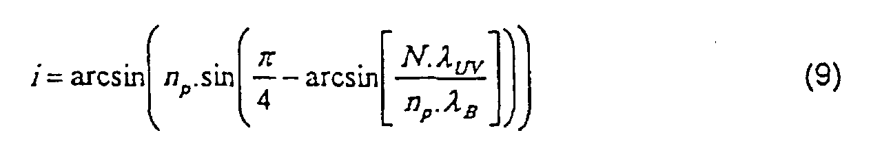
Ainsi, soit en scindant le faisceau d'insolation en trois faisceaux suivant trois prismes orientés suivant des incidences angulaires légèrement différentes, soit en tournant successivement avec précision (platine de rotation) le même prisme d'un angle approprié, les trois réseaux de Bragg de légères différences de longueurs d'onde caractéristiques (quelques nm, par exemple) sont insolés, simultanément dans le cas du premier procédé et séquentiellement dans le second cas.So either by splitting the sunshine beam into three beams along three prisms oriented along angular angles slightly different, either by turning successively with precision (turntable) the same prism from an appropriate angle, the three Bragg gratings of light characteristic wavelength differences (a few nm, for example) are exposed, simultaneously in the case of the first process and sequentially in the second case.
La zone spatiale insolée est importante (quelques mm de long sur 100 µm de large typiquement) de sorte que les contraintes de positionnement de la fibre sur le support d'insolation ne sont pas limitantes.The exposed area is large (a few mm long typically 100 µm wide) so that the constraints of positioning of the fiber on the insulating support are not limiting.
La taille de la rosette est fonction du rayon de courbure des
fibres. Une rosette de 2 cm de large sur 5 cm de long est aisément réalisable et
il semble possible de réaliser une rosette de plus petites dimensions (6x9 mm2)
selon la publication de H.W. Haslasch et J.S. Sirkis (Appl. Opt., vol. 30, n° 28,
1991, pages 4069-4080).The size of the rosette is a function of the radius of curvature of the fibers. A
Après insolations, la rosette doit pouvoir être manipulée sans risque de détérioration tout en conservant les orientations précises d'insolation.After exposure, the rosette must be able to be handled without risk of deterioration while retaining precise directions of sunshine.
Les fibres sont ensuite collées sur un support flexible. Il est aussi possible de noyer la rosette prépositionnée dans un liquide polymérisant afin de solidifier le montage et le rendre manipulable en situation industrielle.The fibers are then bonded to a flexible support. It is also possible to drown the pre-positioned rosette in a polymerizing liquid in order to solidify the assembly and make it easy to handle in an industrial situation.
La figure 7 illustre un exemple de support de rosette à trois
jauges pour le positionnement de la fibre à insoler, avec un support flexible 24,
une fibre optique silice 25, des supports de positionnement 26, des réseaux de
Bragg photo-inscrits 27, avec maintien en traction 28.FIG. 7 illustrates an example of a rosette support with three
gauges for positioning the fiber to be exposed, with a
La rosette peut être interrogée de diverses manières: l'interrogation temporelle, fréquentielle ou en cohérence. Ces solutions sont cependant peu utilisées dans la pratique du fait de la complexité de l'électronique de détection et la solution consiste plutôt à employer le multiplexage optique en longueur d'onde.The rosette can be interrogated in various ways: temporal, frequency or coherent interrogation. These solutions are however little used in practice due to the complexity of detection electronics and the solution is rather to use the wavelength optical multiplexing.
Le principe du multiplexage optique a été déjà décrit dans de nombreux brevets et publications. Citons, en particulier, le brevet WO 86/01286 déposé par G. Meltz, W.H. Glenn et E. Snitzer, ou bien encore le brevet US 5191458 déposé par D.R. Lyons et S.M. Reich.The principle of optical multiplexing has already been described in numerous patents and publications. Let us cite, in particular, patent WO 86/01286 filed by G. Meltz, W.H. Glenn and E. Snitzer, or even the US patent 5191458 filed by D.R. Lyons and S.M. Reich.
Le principe de l'interrogation en longueur d'onde a déjà été décrit : soit le capteur est passif, alors il se contente de renvoyer un signal optique (de spectre étroit) en réflexion, soit le capteur est actif et alors il réémet son propre rayonnement après avoir été stimulé par un faisceau optique d'interrogation.The principle of wavelength interrogation has already been describes: either the sensor is passive, then it just sends back a signal optical (narrow spectrum) in reflection, either the sensor is active and then it re-emits its own radiation after being stimulated by an optical beam question mark.
Ce dernier cas (capteur actif) correspond à une conception de capteur laser dans lequel les contraintes modifient la condition de contre-réaction (le plus souvent spectralement) d'un laser à fibre en particulier. Un tel dispositif est décrit dans certaines publications dont la publication récente de S. Melle et al. (IEEE Phot. Tech. Lett., vol. 5, 1993, pages 263-266).The latter case (active sensor) corresponds to a design of laser sensor in which the stresses modify the feedback condition (most often spectrally) of a fiber laser in particular. Such device is described in certain publications including the recent publication of S. Melle et al. (IEEE Phot. Tech. Lett., Vol. 5, 1993, pages 263-266).
Dans le cas d'un capteur passif, soit une source spectrale large (diode superluminescente), soit un laser accordable (de largeur spectrale inférieure à celle du réseau) servent de faisceau optique d'interrogation. La détection rapide emploie, le plus souvent, un interféromètre de Fabry-Perot accordable mais d'autres solutions sont également exploitables (interféromètre de Mach-Zehnder, ..).In the case of a passive sensor, i.e. a wide spectral source (superluminescent diode), or a tunable laser (of spectral width lower than that of the network) serve as interrogation optical beam. The rapid detection most often uses a Fabry-Perot interferometer tunable but other solutions can also be used (interferometer by Mach-Zehnder, ..).
Deux exemples de circuits de multiplexage optique sont illustrés sur les figures 8A et 8B. Ces figures décrivent un réseau de capteurs à rosettes de Bragg interrogés en réflexion et le traitement du signal associé, respectivement pour une modulation en longueur d'onde d'interrogation (figure 8A) et pour une modulation en longueur d'onde de lecture ("scanning") (figure 8B).Two examples of optical multiplexing circuits are illustrated in Figures 8A and 8B. These figures describe a network of sensors Bragg rosettes questioned in reflection and the processing of the associated signal, respectively for an interrogation wavelength modulation (figure 8A) and for modulation in reading wavelength ("scanning") (figure 8B).
Sur la figure 8A est représentée une source optique modulable
en longueur d'onde 30, reliée à un coupleur optique 31, en fibres optiques dont
une branche est reliée à un photodétecteur 32 suivi d'un module d'acquisition 33
et d'un modulateur 34, lui-même relié à la source 31. Chaque rosette est
composée de trois jauges J1, J2 et J3.FIG. 8A shows a modular optical source
in
Sur la figure 8B une source optique à large bande spectrale 36
est reliée à un coupleur optique 37 en fibres optiques, dont la seconde branche
est reliée à un interféromètre de Fabry-Perot accordable 38 et à un module
d'acquisition 39. Sur cette figure sont également représentées les rosettes R1 et
R2 et les jauges J1, J2 et J3. In FIG. 8B a broad spectral band optical source 36
is connected to an optical coupler 37 made of optical fibers, the second branch of which
is connected to a tunable Fabry-
La manière dont sont reliés les réseaux de Bragg sur la ligne de mesure (ici, en série) n'est donnée qu'à titre indicatif. Toute topologie est envisageable au niveau de chaque jauge.The way in which the Bragg gratings are connected on the line measurement (here, in series) is given for information only. Any topology is possible at each gauge.
Ces techniques de démultiplexage peuvent également être étendues aux procédés d'asservissement permettant de "suivre" en temps réel les déplacements spectraux des réseaux de Bragg comme l'ont montré A.D. Kersey, T.A. Berkoff et W.W. Morey (Opt. Lett., vol. 18, n° 16, 1993, pages 1370-1372).These demultiplexing techniques can also be extended to enslavement processes enabling "tracking" in real time the spectral displacements of the Bragg gratings as shown by A.D. Kersey, T.A. Berkoff and W.W. Morey (Opt. Lett., Vol. 18, n ° 16, 1993, pages 1370-1372).
Le circuit comporte autant de rosettes que de points de mesure. Les figures 8A et 8B représentent deux rosettes à titre d'exemple.The circuit has as many rosettes as points of measured. Figures 8A and 8B show two rosettes by way of example.
La rosette définie dans l'invention peut exploiter un phénomène physique d'accord de phase (réseaux de Bragg) mais aussi l'interférométrie à deux ondes (Michelson et Mach-Zehnder) et à ondes multiples (Fabry-Perot).The rosette defined in the invention can exploit a phenomenon phase agreement physics (Bragg gratings) but also interferometry at two waves (Michelson and Mach-Zehnder) and multiple waves (Fabry-Perot).
Après avoir montré la mise en oeuvre d'une telle rosette à réseaux de Bragg, ainsi que son traitement du signal associé, on va à présent compléter la mise en oeuvre d'une telle rosette exploitant spécifiquement l'interférométrie.After showing the implementation of such a rosette at Bragg gratings, as well as its associated signal processing, we will now complete the implementation of such a rosette specifically exploiting interferometry.
On a décrit précédemment le problème de la sensibilité croisée à la température et aux contraintes et on a montré, dans le cas des réseaux de Bragg, comment supprimer l'effet dû à la température pour ne mesurer que l'effet dû à la contrainte principale longitudinale recherchée et ceci, indépendamment de la position de la rosette dans son plan si celle-ci est constituée de trois jauges.The problem of cross-sensitivity has been described previously to temperature and constraints and we have shown, in the case of networks of Bragg, how to remove the effect due to temperature to measure only the effect due to the main longitudinal stress sought and this, regardless of the position of the rosette in its plane if it is consisting of three gauges.
Les rosettes composées de capteurs interférométriques sont soumises aux mêmes problèmes de sensibilité croisée aux contraintes et à la température. Ainsi le dispositif de rosette optique de l'invention peut exploiter des réseaux de Bragg ou des interféromètres.The rosettes composed of interferometric sensors are subject to the same problems of cross-sensitivity to constraints and temperature. Thus the optical rosette device of the invention can exploit Bragg gratings or interferometers.
Dans ce qui suit, on va détailler le comportement des transducteurs interférométriques, leurs réalisations pratiques ainsi que le traitement du signal qui leur est associé. In what follows, we will detail the behavior of interferometric transducers, their practical achievements as well as the processing of the signal associated with them.
Contrairement aux réseaux de Bragg où l'information est traduite par une longueur d'onde, les transducteurs interférométriques fournissent une information sous forme d'un déphasage optique. L'interféromètre a alors pour but de traduire cette variation de phase en une variation d'intensité et c'est cette variation d'intensité qui est effectivement observée afin d'en déduire la variation de phase, la loi de conversion de phase en intensité étant connue et dépendante du type d'interféromètre.Unlike Bragg gratings where information is translated by a wavelength, the interferometric transducers provide information in the form of an optical phase shift. The interferometer then aims to translate this phase variation into a intensity variation and it is this variation in intensity which is actually observed in order to deduce the phase variation, the law of phase to intensity conversion being known and dependent on the type of interferometer.
Ce type de rosette optique nécessite donc l'emploi d'une source optique de longueur de cohérence supérieure à la différence de chemin optique caractéristique de l'interféromètre (typiquement de l'ordre de quelque nm à quelques cm). Les sources optiques les plus utilisées sont alors des diodes laser en vertu de leur cohérence temporelle suffisante et de leur intégrabilité compatible avec les applications de capteurs à fibres optiques.This type of optical rosette therefore requires the use of a optical source with a coherence length greater than the path difference optical characteristic of the interferometer (typically of the order of a few nm a few cm). The most used optical sources are then diodes laser by virtue of their sufficient temporal coherence and their integrability compatible with fiber optic sensor applications.
La loi générale reliant le déphasage induit aux paramètres
physiques à mesurer (pression, température et contraintes) s'exprime sous la
forme :
Pour une fibre monomode en silice à une longueur d'onde de
850 nm, les coefficients expérimentaux ont pour valeurs moyennes (indicatives) :
(l'allongement relatif s'écrit :
Suivant le type d'interféromètre, les rosettes sont conçues différemment et la loi d'intensité qui en résulte est spécifique.Depending on the type of interferometer, the rosettes are designed differently and the resulting law of intensity is specific.
Une fois les déphasages Δ1, Δ2 et Δ3 des jauges
respectivement 1, 2 et 3 mesurés, la contrainte est obtenue en appliquant à
nouveau la formule (4) en substituant le terme Δ i - Δ 0 / iau terme
Δλi = λi - λ 0 / i et χε.L au terme ξ1 dans les formules (3), (5), (6), (7) et (8).Once the phase differences Δ 1 , Δ 2 and Δ 3 of the
Une rosette de ce type est décrite dans la publication de J.S. Sirkis et C.E. Taylor, Exp. Mech., 1988, pages 170-176 et de J.S. Sirkis et H.W. Haslach, J. of Light. Tech., vol 8, n° 10, 1990, pages 1497-1503. Sa description est illustrée sur la figure 9A et sa conception ainsi que l'électronique d'acquisition sont décrites dans ces publications.A rosette of this type is described in the publication by J.S. Sirkis and C.E. Taylor, Exp. Mech., 1988, pages 170-176 and by J.S. Sirkis and H.W. Haslach, J. of Light. Tech., Vol 8, n ° 10, 1990, pages 1497-1503. Its description is illustrated in FIG. 9A and its design as well as the acquisition electronics are described in these publications.
Cette rosette est conçue pour déterminer une contrainte longitudinale seulement. Le principe consiste à choisir une configuration géométrique telle que représentée sur la figure 9A afin que la différence de chemins optiques soit proportionnelle à la contrainte appliquée selon l'axe X de la figure. Les deux faisceaux émergeant des deux fibres (de mesure et de référence) sont projetés sur un écran comme représenté sur la figure 9B, afin d'analyser la figure d'interférences (principe des fentes d'Young, les coeurs des deux fibres jouant le rôle des fentes).This rosette is designed to determine a stress longitudinal only. The principle is to choose a configuration geometric as shown in Figure 9A so that the difference in optical paths is proportional to the stress applied along the X axis of the figure. The two bundles emerging from the two fibers (measuring and reference) are projected on a screen as shown in FIG. 9B, so to analyze the interference pattern (principle of Young's slits, the hearts of two fibers playing the role of slits).
La figure 9A illustre une jauge à interféromètre de Mach-Zehnder pour la mesure d'une contrainte longitudinale (d'après Sirkis et Taylor) : respectivement la constitution et le montage expérimental. La figure 9B illustre une rosette à interféromètres de Mach-Zehnder.Figure 9A illustrates a Mach-Zehnder interferometer gauge for the measurement of a longitudinal stress (after Sirkis and Taylor): respectively the constitution and the experimental set-up. Figure 9B illustrates a rosette with Mach-Zehnder interferometers.
Sur la figure 9A on a une fibre de mesure 40 et une fibre de
référence 41 collée en cercle. Sur la figure 9B on a un écran 42, une poutre 43,
une lame séparatrice 44, des objectifs de microscope 45, des miroirs 46 et un
laser 47.In FIG. 9A, there is a
La loi d'intensité et le traitement du signal des rosettes à interféromètres de Mach-Zehnder sont les mêmes que pour les rosettes à interféromètres de Michelson que l'on va maintenant décrire.The intensity law and the signal processing of the rosettes at Mach-Zehnder interferometers are the same as for rosettes with Michelson interferometers which we will now describe.
Cette rosette et sa réalisation sont décrites dans la publication de R.M. Measures intitulée "Fiber Optic Fabry-Perot Strain Rosettes", Smart. Mater. Struct., vol. 1, 1992, pages 227-232. Elle est représentée sur la figure 2B.This rosette and its realization are described in the publication by R.M. Measures entitled "Fiber Optic Fabry-Perot Strain Rosettes", Smart. Mater. Struct., Vol. 1, 1992, pages 227-232. It is shown in Figure 2B.
L'interférométrie est réalisée entre chaque faisceau optique de mesure réfléchi dans les trois bras de mesure avec le signal réfléchi provenant du bras de référence (non soumis aux contraintes à déterminer).Interferometry is performed between each optical beam of measurement reflected in the three measurement arms with the reflected signal from of the reference arm (not subject to the constraints to be determined).
Par construction, le déphasage Δ induit par les contraintes et la température peut être choisi faible (inférieur à π) de sorte que l'évolution de l'intensité s'effectue sur le flanc de la courbe de transfert de l'interféromètre de Michelson et de Mach-Zehnder, comme représenté sur la figure 10 qui illustre une courbe de l'intensité en fonction du retard optique R (déphasage), avec un interféromètre à deux ondes.By construction, the phase shift Δ induced by the constraints and the temperature can be chosen low (less than π) so that the evolution of the intensity is carried out on the side of the transfer curve of the interferometer of Michelson and Mach-Zehnder, as shown in Figure 10 which illustrates an intensity curve as a function of the optical delay R (phase shift), with a two wave interferometer.
Pour cela, la différence de longueur entre le bras de mesure et le bras de référence doit être de l'ordre de quelques mm à quelques cm.For this, the difference in length between the measuring arm and the reference arm should be of the order of a few mm to a few cm.
La loi de conversion des interféromètres de Michelson et de
Mach-Zehnder est :
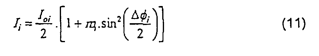
Ii est l'intensité observée fonction du déphasage Δ i (projeté sur l'écran dans le cas de la figure 9B) et Ioi est l'intensité laser injecté. L'intensité observée est directement convertie en courant par une photodiode de mesure dont le courant peut être mesuré par un picoampèremètre ou par un amplificateur (circuit à phototransistor) tel que décrit dans la publication de Sirkis et Taylor. I i is the intensity observed as a function of the phase shift Δ i (projected on the screen in the case of FIG. 9B) and I oi is the laser intensity injected. The intensity observed is directly converted into current by a measuring photodiode, the current of which can be measured by a pico-ammeter or by an amplifier (phototransistor circuit) as described in the publication by Sirkis and Taylor.
La sensibilité des jauges est maximale à un point de fonctionnement situé à mi-hauteur (voir figure 10); il est cependant difficile d'ajuster le point de fonctionnement simultanément pour les trois jauges (en changeant la longueur d'onde), d'où la nécessité d'un compromis.The sensitivity of the gauges is maximum at a point of operating at mid-height (see Figure 10); it is however difficult to adjust the operating point simultaneously for the three gauges (in changing the wavelength), hence the need for a compromise.
Une autre solution, employée par R.M. Measures (publication déjà citée plus haut) et J.S. Sirkis consiste à réaliser un comptage de franges si la différence de chemins optiques est importante (de l'ordre du mètre et plus). Le problème tient à ce que le comptage ne procure qu'une mesure absolue et non une mesure relative, ce qui implique que le signe de la contrainte soit connu a priori, ce qui est rarement le cas dans la pratique.Another solution, used by R.M. Measures (publication already mentioned above) and J.S. Sirkis consists in counting fringes if the difference in optical paths is significant (of the order of a meter or more). The problem is that counting provides only an absolute measure and not a relative measure, which implies that the sign of the constraint is known a a priori, which is rarely the case in practice.
Une solution, développée par la Société CSO en France consiste alors à scinder le faisceau de mesure en deux, l'un observé directement, l'autre traversant un parcours optique correspondant à un déphasage de quart d'onde. Ainsi, deux fonctions d'interférence sont observées en quadrature, ce qui permet de lever l'indétermination concernant le signe de la contrainte appliquée.A solution, developed by the CSO Company in France then consists in splitting the measurement beam into two, one observed directly, the other crossing an optical path corresponding to a quarter wave phase shift. Thus, two interference functions are observed in quadrature, which makes it possible to lift the indeterminacy concerning the sign of the applied stress.
Cette solution a été adoptée par J.S. Sirkis qui a placé deux photodiodes proches l'une de l'autre sur l'écran sur lequel les fentes d'Young sont projetées. Ainsi, en observant les deux signaux légèrement en déphasage émis par chacune des deux photodiodes, il est possible de déterminer le sens de propagation des franges. Le compteur compte si le premier détecteur déclenche sur une frange avant le deuxième et réciproquement, le compteur décompte si le deuxième déclenche avant le premier.This solution was adopted by J.S. Sirkis who placed two photodiodes close to each other on the screen on which the Young slits are projected. So, by observing the two signals slightly out of phase emitted by each of the two photodiodes, it is possible to determine the direction of spread of fringes. The counter counts if the first detector triggers on a fringe before the second and vice versa, the counter counts down if the second triggers before the first.
Pour des raisons de cohérence temporelle, un seul laser doit être utilisé dans les deux montages (Mach-Zehnder et Michelson).For reasons of temporal consistency, only one laser must be used in both assemblies (Mach-Zehnder and Michelson).
La mise en réseau de plusieurs rosettes se fait en répétant le
motif illustré sur la figure 11, en plaçant plusieurs coupleurs 1x4 (50) en série, ou
en associant autant de lasers 51 que de rosettes 52. Sur cette figure sont
également représentées des photodiodes 53, des fibres de mesures 54, une
fibre référence 55, des revêtements réfléchissants (multicouche électrique) 56, et
des coupleurs 1x2 (57 et 58). De même, les miroirs peuvent être
avantageusement réalisés par des réseaux de Bragg photoinscrits de longueurs
d'onde caractéristiques recouvrant la longueur d'onde du laser utilisé.The networking of several rosettes is done by repeating the
motif illustrated in FIG. 11, by placing several 1x4 couplers (50) in series, or
by associating as many lasers 51 as
Cette rosette est illustrée sur la figure 2C. Sa conception est décrite dans la publication de R.M. Measures citée plus haut. L'interférométrie est réalisée sur toute la longueur sensible de chaque jauge (c'est-à-dire, entre la soudure semi-réflectrice et le miroir déposé en bout de fibre).This rosette is illustrated in Figure 2C. Its design is described in the publication of R.M. Measures cited above. Interferometry is carried out over the entire sensitive length of each gauge (i.e. between the semi-reflective welding and the mirror deposited at the end of the fiber).
La variation de phase induite (par pression, température ou
contraintes) produit une variation d'intensité transmise selon la fonction d'Airy,
bien connue, représentée sur la figure 12. Cette figure illustre les fonctions de
transfert typiques d'un interféromètre de Fabry-Perot pour plusieurs
coefficients R=R1=R2.

La connexion optique est illustrée sur la figure 13, avec une
source optique (diode laser) 60, un coupleur 1x3 (61), une rosette 62, des fibres
de mesure 63, des soudures semi-réflectrices 64, des photodiodes 65 et des
coupleurs optiques 1x2 (66).The optical connection is illustrated in Figure 13, with a
optical source (laser diode) 60, 1x3 coupler (61),
Suivant les deux principes énoncés précédemment (évolution de l'intensité sur le flanc de la courbe de réponse ou bien comptage de franges), les mêmes principes de détection que pour les rosettes d'interféromètres de Mach-Zehnder et de Michelson peuvent être appliqués.Following the two principles set out above (evolution intensity on the side of the response curve or counting of fringes), the same detection principles as for the interferometer rosettes of Mach-Zehnder and Michelson can be applied.
Claims (14)
- Rosette-type, optical microsystem of strain gauges having dielectric guides for measuring a system of strains applied to a part, said microsystem comprising at least one rosette formed by at least two strain gauges having dielectric guides (J1, J2, J3) which are not parallel and have known orientations, characterized in that the strain gauges are Bragg networks (RB1, RB2, RB3), in that the part is subject to a strain having a single component contained in the plane of the gauges and in that a calculating circuit, which delivers a result independent of the temperature, makes it possible to determine said strain by solving the following system of equations:λ1, λ2 and λ3 being respective wavelengths of three Bragg networks constituting the rosette, said wavelengths being very close to one another and λ1, λ2 and λ3 are the characteristic wavelengths in the absence of deformations and at a reference temperature To, ζ1 being a coefficient linking the characteristic wavelength with the deformation and ζ2 a thermal expansion coefficient, the two angles β1 and β2 being of a random, but known nature and non-zero modulo Π, characterizing the rosette and α being the angle formed by the orientation of the main strain to be determined with the orientation of the rosette reference strain gauge, the parameters d and r being respectively the half-sum and half-difference of the main deformations to be determined.

- Optical microsystem according to claim 1, characterized in that the strain gauges are photo-inscribed Bragg networks (RB1, RB2, RB3).
- Optical microsystem according to claim 1, characterized in that the Bragg networks are positioned at 120 or 45° from one another.
- Optical microsystem according to claim 1, characterized in that the said three networks are simultaneously or successively inscribed by the same optical irradiation beam.
- Optical microsystem according to claim 1, characterized in that the three networks are not simultaneously inscribed and can have different characteristic wavelengths.
- Optical microsystem according to any one of the preceding claims, characterized in that the dielectric guides are optical fibres.
- Optical microsystem according to claim 1, characterized in that it comprises at least one dielectric guide, with or without polarization maintenance, in which are incorporated the strain gauges.
- Optical microsystem according to claim 7, characterized in that the elongation transducers are surface-bonded or are embedded within the locally planar, support material, whose deformations are to be determined.
- Optical microsystem according to claim 7, characterized in that the transducers are Bragg networks, which function by the phase tuning effect, and in that the guides are monomode and photosensitive, and advantageously monomode.
- Optical microsystem according to claim 7, characterized in that the transducers function by an interferometric effect and in that the guides are monomode.
- Optical microsystem according to claim 1, characterized in that each strain gauge measures an optical path variation, which is a function of the strain to be measured and which induces a spectral displacement.
- Optical microsystem according to claim 1, characterized in that each strain gauge measures an optical path variation, which is a function of the strain to be measured and which induces a displacement of the interference fringes.
- Optical microsystem according to any one of the preceding claims, characterized in that the gauges constituting the rosette are positioned in series on the same dielectric guide.
- Optical microsystem according to any one of the claims 1 to 12, characterized in that it has a configuration of a balanced Sagnac interferometer type using a 50% reflection coupler in the spectral band of use, said configuration being constituted by a single guide plane and permitting the inclusion of a rosette between two planes of a material.
Applications Claiming Priority (2)
| Application Number | Priority Date | Filing Date | Title |
|---|---|---|---|
| FR9413845 | 1994-11-18 | ||
| FR9413845A FR2727203B1 (en) | 1994-11-18 | 1994-11-18 | DOSE ELECTRIC GUIDE ROSETTE-TYPE OPTICAL MICRO-SYSTEM FOR MEASURING A LONGITUDINAL CONSTRAIN IN A PLANE STRUCTURE |
Publications (3)
| Publication Number | Publication Date |
|---|---|
| EP0713084A2 EP0713084A2 (en) | 1996-05-22 |
| EP0713084A3 EP0713084A3 (en) | 1997-01-02 |
| EP0713084B1 true EP0713084B1 (en) | 2001-08-01 |
Family
ID=9468942
Family Applications (1)
| Application Number | Title | Priority Date | Filing Date |
|---|---|---|---|
| EP95402572A Expired - Lifetime EP0713084B1 (en) | 1994-11-18 | 1995-11-16 | Optical micro-system of rosette strain gauge types with dielectrical guides for measuring a longitudinal strain of a planar structure |
Country Status (5)
| Country | Link |
|---|---|
| US (1) | US5726744A (en) |
| EP (1) | EP0713084B1 (en) |
| CA (1) | CA2162954A1 (en) |
| DE (1) | DE69521971T2 (en) |
| FR (1) | FR2727203B1 (en) |
Cited By (1)
| Publication number | Priority date | Publication date | Assignee | Title |
|---|---|---|---|---|
| WO2009149908A1 (en) | 2008-06-12 | 2009-12-17 | Hottinger Baldwin Messtechnik Gmbh | Optical extension sensor |
Families Citing this family (44)
| Publication number | Priority date | Publication date | Assignee | Title |
|---|---|---|---|---|
| NO307314B1 (en) * | 1997-12-05 | 2000-03-13 | Optoplan As | Device for registration of buoy load |
| GB9824756D0 (en) | 1998-11-11 | 1999-01-06 | Europ Economic Community | A strain sensor and strain sensing apparatus |
| US6157448A (en) * | 1999-10-08 | 2000-12-05 | Uniopt Co., Ltd. | Birefringence measurement optical system and high spatial resolution polarimetric apparatus |
| DE10004384C2 (en) * | 2000-02-02 | 2003-04-03 | Daimler Chrysler Ag | Arrangement and method for detecting strains and temperatures and their changes on a carrier, in particular one consisting of metal, plastic or ceramic carrier, applied topcoat |
| JP3797880B2 (en) * | 2001-02-26 | 2006-07-19 | 沖電気工業株式会社 | FBG strain sensor |
| NO334515B1 (en) * | 2002-03-13 | 2014-03-31 | Light Structures As | Fiber optic sensor package |
| FR2864202B1 (en) * | 2003-12-22 | 2006-08-04 | Commissariat Energie Atomique | INSTRUMENT TUBULAR DEVICE FOR TRANSPORTING A PRESSURIZED FLUID |
| DK1709416T3 (en) * | 2004-01-23 | 2018-06-18 | Lm Wind Power Int Tech Ii Aps | Device comprising a system adapted for use in temperature compensation for load measurements in fiber-reinforced structures |
| WO2006000212A1 (en) * | 2004-06-25 | 2006-01-05 | Conti Temic Microelectronic Gmbh | Electrical subassembly comprising a protective sheathing |
| WO2006075972A1 (en) * | 2005-01-14 | 2006-07-20 | Sif Universal Pte Ltd | Bending sensor arrangement |
| US7953559B2 (en) * | 2005-04-28 | 2011-05-31 | Caterpillar Inc. | Systems and methods for maintaining load histories |
| US7487066B2 (en) * | 2005-04-28 | 2009-02-03 | Caterpillar Inc. | Classifying a work machine operation |
| DE102005030751A1 (en) * | 2005-06-29 | 2007-01-11 | Hottinger Baldwin Messtechnik Gmbh | Optical strain gauge |
| DE102005030753B4 (en) * | 2005-06-29 | 2018-04-12 | Hottinger Baldwin Messtechnik Gmbh | Optical strain gauge |
| US7472599B2 (en) * | 2006-06-30 | 2009-01-06 | Caterpillar Inc. | Strain sensing device |
| US7908928B2 (en) | 2006-10-31 | 2011-03-22 | Caterpillar Inc. | Monitoring system |
| WO2008090348A1 (en) * | 2007-01-24 | 2008-07-31 | Gkn Aerospace Services Limited | Temperature sensing |
| DE102007008464B4 (en) * | 2007-02-19 | 2012-01-05 | Hottinger Baldwin Messtechnik Gmbh | Optical strain gauge |
| EP2260281B1 (en) | 2008-03-31 | 2017-05-03 | Vestas Wind Systems A/S | Optical transmission strain sensor for wind turbines |
| US7646946B2 (en) * | 2008-04-03 | 2010-01-12 | The United States Of America As Represented By The Secretary Of The Navy | Intensity modulated fiber optic strain sensor |
| GB2461532A (en) * | 2008-07-01 | 2010-01-06 | Vestas Wind Sys As | Sensor system and method for detecting deformation in a wind turbine component |
| GB2461566A (en) * | 2008-07-03 | 2010-01-06 | Vestas Wind Sys As | Embedded fibre optic sensor for mounting on wind turbine components and method of producing the same. |
| GB2463696A (en) * | 2008-09-22 | 2010-03-24 | Vestas Wind Sys As | Edge-wise bending insensitive strain sensor system |
| GB2466433B (en) | 2008-12-16 | 2011-05-25 | Vestas Wind Sys As | Turbulence sensor and blade condition sensor system |
| WO2010138813A2 (en) * | 2009-05-29 | 2010-12-02 | The Board Of Trustees Of The University Of Illinois | High resolution large displacement/crack sensor |
| GB2472437A (en) | 2009-08-06 | 2011-02-09 | Vestas Wind Sys As | Wind turbine rotor blade control based on detecting turbulence |
| US8195013B2 (en) * | 2009-08-19 | 2012-06-05 | The United States Of America, As Represented By The Secretary Of The Navy | Miniature fiber optic temperature sensors |
| GB2477529A (en) | 2010-02-04 | 2011-08-10 | Vestas Wind Sys As | A wind turbine optical wind sensor for determining wind speed and direction |
| EP2556332A4 (en) * | 2010-04-09 | 2017-03-15 | Intuitive Surgical Operations, Inc. | Strain sensing with optical fiber rosettes |
| FR2961871B1 (en) * | 2010-06-25 | 2013-04-12 | Renault Sa | MOTOR VEHICLE WHEEL BEARING COMPRISING AN EFFORTS SENSOR |
| FR3007520A1 (en) | 2013-06-25 | 2014-12-26 | St Microelectronics Crolles 2 | METHOD FOR DETERMINING A FIELD OF THREE-DIMENSIONAL CONSTRAINTS OF AN OBJECT, IN PARTICULAR AN INTEGRATED STRUCTURE, AND CORRESPONDING SYSTEM |
| WO2015080222A1 (en) * | 2013-12-01 | 2015-06-04 | 株式会社シミウス | Strain sensor and manufacturing method for strain sensor |
| DE102014100653B4 (en) * | 2014-01-21 | 2016-01-21 | fos4X GmbH | Rail Measuring System |
| US10861682B2 (en) | 2014-07-31 | 2020-12-08 | iSenseCloud, Inc. | Test wafer with optical fiber with Bragg Grating sensors |
| US10771159B2 (en) | 2014-07-31 | 2020-09-08 | iSenseClound, Inc. | Fiber optic patch and voltage conditioning |
| US10209060B1 (en) * | 2014-07-31 | 2019-02-19 | iSenseCloud, Inc. | Fiber-optic sensors in a rosette or rosette-like pattern for structure monitoring |
| EP3237833A4 (en) * | 2014-12-22 | 2018-06-13 | Sikorsky Aircraft Corporation | Fiber optic weight sensor optimization for landing gear |
| US10732023B2 (en) | 2016-03-24 | 2020-08-04 | Sikorsky Aircraft Corporation | Measurement system for aircraft, aircraft having the same, and method of measuring weight for aircraft |
| EP3258230B1 (en) | 2016-06-13 | 2019-11-13 | Airbus Defence and Space GmbH | Sensor skin with temperature sensor system |
| US10612911B1 (en) * | 2017-09-07 | 2020-04-07 | United States Of America As Represented By The Administrator Of The National Aeronautics And Space Administration | Fiber optic system for monitoring displacement of a structure using quaternion kinematic shape sensing |
| DE102018108399B4 (en) * | 2018-04-10 | 2024-02-29 | Dr. Ing. H.C. F. Porsche Aktiengesellschaft | Motor vehicle body element with a shape monitoring system for a motor vehicle body |
| CN109781300A (en) * | 2018-12-30 | 2019-05-21 | 北京信息科技大学 | It is a kind of based on optical fiber while measure temperature and curvature device and method |
| CN111982000B (en) * | 2020-08-21 | 2021-10-15 | 河北工业大学 | Optical fiber shape reconstruction method and device based on Beta frame |
| DE102021211044A1 (en) | 2021-09-30 | 2023-03-30 | Fraunhofer-Gesellschaft zur Förderung der angewandten Forschung eingetragener Verein | Connection bolts and method of monitoring a connection |
Family Cites Families (6)
| Publication number | Priority date | Publication date | Assignee | Title |
|---|---|---|---|---|
| US4806012A (en) * | 1984-08-13 | 1989-02-21 | United Technologies Corporation | Distributed, spatially resolving optical fiber strain gauge |
| JPH067049B2 (en) * | 1984-08-13 | 1994-01-26 | ユナイテツド テクノロジ−ズ コ−ポレ−シヨン | Optical fiber strainmeter for dispersive and spaced analysis |
| US4890922A (en) * | 1987-02-20 | 1990-01-02 | Litton Systems, Inc. | Thermally compensated reference interferometer and method |
| US5144690A (en) * | 1990-12-03 | 1992-09-01 | Corning Incorporated | Optical fiber sensor with localized sensing regions |
| CA2073162C (en) * | 1991-07-31 | 1999-06-29 | Lee A. Danisch | Fiber optic bending and positioning sensor |
| US5361130A (en) * | 1992-11-04 | 1994-11-01 | The United States Of America As Represented By The Secretary Of The Navy | Fiber grating-based sensing system with interferometric wavelength-shift detection |
-
1994
- 1994-11-18 FR FR9413845A patent/FR2727203B1/en not_active Expired - Fee Related
-
1995
- 1995-10-30 US US08/550,029 patent/US5726744A/en not_active Expired - Lifetime
- 1995-11-15 CA CA002162954A patent/CA2162954A1/en not_active Abandoned
- 1995-11-16 DE DE69521971T patent/DE69521971T2/en not_active Expired - Lifetime
- 1995-11-16 EP EP95402572A patent/EP0713084B1/en not_active Expired - Lifetime
Cited By (2)
| Publication number | Priority date | Publication date | Assignee | Title |
|---|---|---|---|---|
| WO2009149908A1 (en) | 2008-06-12 | 2009-12-17 | Hottinger Baldwin Messtechnik Gmbh | Optical extension sensor |
| DE102008027931A1 (en) | 2008-06-12 | 2010-01-07 | Hottinger Baldwin Messtechnik Gmbh | Optical strain sensor |
Also Published As
| Publication number | Publication date |
|---|---|
| DE69521971D1 (en) | 2001-09-06 |
| EP0713084A3 (en) | 1997-01-02 |
| FR2727203B1 (en) | 1996-12-13 |
| EP0713084A2 (en) | 1996-05-22 |
| DE69521971T2 (en) | 2002-04-04 |
| US5726744A (en) | 1998-03-10 |
| FR2727203A1 (en) | 1996-05-24 |
| CA2162954A1 (en) | 1996-05-19 |
Similar Documents
| Publication | Publication Date | Title |
|---|---|---|
| EP0713084B1 (en) | Optical micro-system of rosette strain gauge types with dielectrical guides for measuring a longitudinal strain of a planar structure | |
| Urrutia et al. | A comprehensive review of optical fiber refractometers: Toward a standard comparative criterion | |
| US11002594B2 (en) | Method and apparatus for distributed sensing | |
| Pevec et al. | Miniature all-fiber Fabry–Perot sensor for simultaneous measurement of pressure and temperature | |
| Chen et al. | Micro-air-gap based intrinsic Fabry-Perot interferometric fiber-optic sensor | |
| EP0434504A1 (en) | Fibre-optical sensor | |
| Wan et al. | Review on speckle-based spectrum analyzer | |
| EP3433575B1 (en) | Optical fibre curvature sensor and measurement device comprising said sensor | |
| EP0647311B1 (en) | Sagnac effect optical gyrometer having a fully integrated structure | |
| WO2006123068A1 (en) | Method and device for determining elongation and strain sensor used for same | |
| EP0360759B1 (en) | Force transducer using optical wave guiding elements integrated in a substrate | |
| EP0986737B1 (en) | Device for reading spectral rays contained in an optical spectrum | |
| Niu et al. | Reflective intensity-demodulated refractometer based on S fiber taper | |
| Li et al. | Micro-cap on 2-core-fiber facet hybrid interferometer for dual-parameter sensing | |
| Zhao et al. | Highly sensitive salinity and temperature measurement based on tapered-SHF MZI fiber laser structure | |
| Martínez-Manuel et al. | Nonlinearity Reduction in a Fiber Fabry-Perot Interferometer Interrogated by a Wavelength Scanning Optical Source | |
| FR3052923A1 (en) | OPTICAL REFLECTOR RESONANT TO MULTIPLE THIN LAYERS OF DIELECTRIC MATERIALS, OPTICAL SENSOR AND LASER AMPLIFICATION DEVICE COMPRISING SUCH A REFLECTOR | |
| EP4097423B1 (en) | System for measuring a plurality of physical parameters at a measurement point with a multimode optical fiber | |
| FR2921482A1 (en) | MULTIMODE OPTICAL FIBER OPTICAL TRANSDUCER, COUPLING MODES, METHOD FOR PRODUCING THE SAME | |
| EP0887619B1 (en) | Feeding and transmission system for optical fibre sensor, integrated in an amagnetic structure, and associated feeding and reception module | |
| Li et al. | On-chip Demodulation Approach based on Microring Resonator for Fiber-optic Vernier Effect Sensing | |
| CN218066800U (en) | Temperature sensing system based on parallel vernier effect | |
| WO2024120735A1 (en) | Device for measuring a physical quantity using the optical vernier effect | |
| WO2024121231A1 (en) | Device for measuring a physical quantity | |
| Idrisov | Optimization of multicore optical fibers with fiber Bragg gratings towards bend and shape sensing |
Legal Events
| Date | Code | Title | Description |
|---|---|---|---|
| PUAI | Public reference made under article 153(3) epc to a published international application that has entered the european phase |
Free format text: ORIGINAL CODE: 0009012 |
|
| AK | Designated contracting states |
Kind code of ref document: A2 Designated state(s): DE GB IT |
|
| PUAL | Search report despatched |
Free format text: ORIGINAL CODE: 0009013 |
|
| AK | Designated contracting states |
Kind code of ref document: A3 Designated state(s): DE GB IT |
|
| 17P | Request for examination filed |
Effective date: 19970606 |
|
| 17Q | First examination report despatched |
Effective date: 19991029 |
|
| GRAG | Despatch of communication of intention to grant |
Free format text: ORIGINAL CODE: EPIDOS AGRA |
|
| GRAG | Despatch of communication of intention to grant |
Free format text: ORIGINAL CODE: EPIDOS AGRA |
|
| GRAH | Despatch of communication of intention to grant a patent |
Free format text: ORIGINAL CODE: EPIDOS IGRA |
|
| GRAH | Despatch of communication of intention to grant a patent |
Free format text: ORIGINAL CODE: EPIDOS IGRA |
|
| GRAA | (expected) grant |
Free format text: ORIGINAL CODE: 0009210 |
|
| AK | Designated contracting states |
Kind code of ref document: B1 Designated state(s): DE GB IT |
|
| REF | Corresponds to: |
Ref document number: 69521971 Country of ref document: DE Date of ref document: 20010906 |
|
| ITF | It: translation for a ep patent filed | ||
| GBT | Gb: translation of ep patent filed (gb section 77(6)(a)/1977) |
Effective date: 20011101 |
|
| REG | Reference to a national code |
Ref country code: GB Ref legal event code: IF02 |
|
| PLBE | No opposition filed within time limit |
Free format text: ORIGINAL CODE: 0009261 |
|
| STAA | Information on the status of an ep patent application or granted ep patent |
Free format text: STATUS: NO OPPOSITION FILED WITHIN TIME LIMIT |
|
| 26N | No opposition filed | ||
| PGFP | Annual fee paid to national office [announced via postgrant information from national office to epo] |
Ref country code: IT Payment date: 20091121 Year of fee payment: 15 Ref country code: GB Payment date: 20091119 Year of fee payment: 15 |
|
| GBPC | Gb: european patent ceased through non-payment of renewal fee |
Effective date: 20101116 |
|
| PG25 | Lapsed in a contracting state [announced via postgrant information from national office to epo] |
Ref country code: GB Free format text: LAPSE BECAUSE OF NON-PAYMENT OF DUE FEES Effective date: 20101116 |
|
| PG25 | Lapsed in a contracting state [announced via postgrant information from national office to epo] |
Ref country code: IT Free format text: LAPSE BECAUSE OF NON-PAYMENT OF DUE FEES Effective date: 20101116 |
|
| PGFP | Annual fee paid to national office [announced via postgrant information from national office to epo] |
Ref country code: DE Payment date: 20121113 Year of fee payment: 18 |
|
| REG | Reference to a national code |
Ref country code: DE Ref legal event code: R119 Ref document number: 69521971 Country of ref document: DE Effective date: 20140603 |
|
| PG25 | Lapsed in a contracting state [announced via postgrant information from national office to epo] |
Ref country code: DE Free format text: LAPSE BECAUSE OF NON-PAYMENT OF DUE FEES Effective date: 20140603 |