EP0712992A2 - Aufbrechvorrichtung für Bohrgestäuge - Google Patents
Aufbrechvorrichtung für Bohrgestäuge Download PDFInfo
- Publication number
- EP0712992A2 EP0712992A2 EP95250224A EP95250224A EP0712992A2 EP 0712992 A2 EP0712992 A2 EP 0712992A2 EP 95250224 A EP95250224 A EP 95250224A EP 95250224 A EP95250224 A EP 95250224A EP 0712992 A2 EP0712992 A2 EP 0712992A2
- Authority
- EP
- European Patent Office
- Prior art keywords
- pipe
- saver sub
- drill
- flats
- lugs
- Prior art date
- Legal status (The legal status is an assumption and is not a legal conclusion. Google has not performed a legal analysis and makes no representation as to the accuracy of the status listed.)
- Withdrawn
Links
- 230000007246 mechanism Effects 0.000 claims abstract description 16
- 238000000034 method Methods 0.000 claims description 5
- 238000005553 drilling Methods 0.000 description 14
- 230000002441 reversible effect Effects 0.000 description 5
- 230000009471 action Effects 0.000 description 1
- 230000004048 modification Effects 0.000 description 1
- 238000012986 modification Methods 0.000 description 1
- 230000008707 rearrangement Effects 0.000 description 1
- 230000037390 scarring Effects 0.000 description 1
- 238000006467 substitution reaction Methods 0.000 description 1
Images
Classifications
-
- E—FIXED CONSTRUCTIONS
- E21—EARTH OR ROCK DRILLING; MINING
- E21B—EARTH OR ROCK DRILLING; OBTAINING OIL, GAS, WATER, SOLUBLE OR MELTABLE MATERIALS OR A SLURRY OF MINERALS FROM WELLS
- E21B19/00—Handling rods, casings, tubes or the like outside the borehole, e.g. in the derrick; Apparatus for feeding the rods or cables
- E21B19/16—Connecting or disconnecting pipe couplings or joints
- E21B19/167—Connecting or disconnecting pipe couplings or joints using a wrench adapted to engage a non circular section of pipe, e.g. a section with flats or splines
Definitions
- the drill string In drilling, it is common to extend the length of the drill string as the drill proceeds by adding individual threaded drill pipe sections to the drill string.
- the drilling action of the bit at the end of the drill string is usually accomplished by rotating the entire drill string in one direction continuously.
- the rotation is induced by a drilling unit at the surface which rotates an output shaft threaded to the last section of pipe in the drill string.
- the direction of rotation of the output shaft drill is the same direction that makes up the threaded connections between the individual sections of pipe and the rotation of the output shaft is therefore efficiently transferred to the drill pipe at the cutting face.
- the output shaft When the pipe is to be removed from the drill string after the drilling is completed, the output shaft must be operated in a reverse direction to unthread the individual pipe from the drill string. However, in the absence of external forces, it is difficult to control which of the many threaded connections will be the first broken by this reverse rotation.
- a drill unit which has a mechanism to move the output shaft along the machine at least the length of a section of the drill pipe.
- the output shaft is retracted so that the uppermost section of pipe is contained within the drill unit.
- the end of the next lower pipe is prevented from rotating with a wrench or similar locking method attached to the drill unit.
- the output shaft is then rotated in the reverse or unthreading direction while an additional person assists the breaking effort with a handheld pipe wrench.
- This method is relatively fast, but requires two people. Therefore, a need exists for improved mechanism to assist in breaking out the sections of pipe once the drilling has been completed.
- a mechanism for securing the output shaft of the drill unit to a pipe in a drill string for rotation with the output shaft.
- An end of the pipe is threaded to the output shaft of the drill unit through a replaceable saver sub securely attached to the output shaft.
- the end of the pipe also has a pair of opposed flats.
- the mechanism includes a slidable collar mounted on the saver sub for sliding motion between a first position spaced from the end of the pipe and a second position extending over the end of the pipe. As the outer collar moves from the first position to the second position, the outer collar engages the opposed flats on the end of the pipe to secure the pipe for rotation with the output shaft.
- the saver sub has opposed flats which extend along its length while the slidable collar has opposed lugs which engage the flats through the entire range of motion of the slidable outer collar between the first and second positions to insure the slidable collar always rotates with the saver sub.
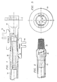
- a mechanism 10 is illustrated which can be used on the saver sub 16 of a drill unit to assist in removal of the uppermost section of the drill pipe 14 in a drill string.
- a drill unit will have a mechanism, not shown, to rotate an output shaft.
- the saver sub 16 is attached to the output shaft for rotation with it.
- the saver sub is replaceable, and if it wears, only the saver sub needs to be replaced rather than repairing the whole drill unit.
- the drill unit rotates the pipe 14 for drilling through the output shaft and saver sub 16.
- the drill motor is reversible so that the saver sub 16 can be rotated in a first direction for drilling and making up the threads of the various sections of pipe and in the reverse direction to break out or unthread the threaded connections in the drill pipe.
- the saver sub 16 is mounted on a mechanism within the drill unit which allows the saver sub 16 to be moved along the drill unit along the axis of the drill string to advance the drill string in a manner well known in the industry. As the drilling is ongoing, the saver sub will rotate in the drilling direction to rotate the drilling bit at the drilling face and the drill unit will advance the drill string into the hole as the drilling continues.
- each individual section of pipe must be removed from the drill string as the drill string is withdrawn from the borehole.
- the saver sub 16 is moved to the position within the drill unit so that the wrench mounted on the drill unit can be secured to the upper end of the next section of drill pipe in the drill string to which pipe 14 is secured.
- the saver sub 16 has a pair of opposed flats 18 which extend from the front end 20 of the saver sub along a portion of its length.
- the flats are formed 180° apart from each other on opposite sides of the axis of rotation 22.
- the threaded portion 23 of saver sub 16 receives and threads to the pipe 14.
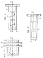
- a slidable collar 24, seen in FIGURES 1, 3 and 4 has a through bore 26 permitting the collar to be slid over the front end of the saver sub 16.
- Inwardly facing lugs 28 on the collar 24 extend from the bore and engage or slide along the flats 18 on the saver sub.
- the width of the lugs 28 is slightly more than the width of the flats 18, permitting the slidable collar 24 to slide along the saver sub 16 yet rotate with the saver sub.
- the drill pipe 14, as seen in FIGURES 1 and 2, can be seen to include opposed flats 30 formed at threaded end 32.
- the slidable collar 24 When the slidable collar 24 is in the disengaged position, as seen in the upper portion of FIGURE 1, the slidable collar 24 is completely out of contact with the drill pipe 14, permitting the drill pipe to be threaded into or threaded out of the saver sub 16.
- the slidable collar 24 is moved into the engaged position, as shown in the lower part of FIGURE 1, a portion of the lugs 28 slide over and engage the flats 30 on the drill pipe 14. Another portion of the lugs 28 remain in engagement with flats 18 on the saver sub 16.
- the slidable collar 24 therefore locks the saver sub 16 to the drill pipe 14 for joint rotation independent of the threaded connection between threads 32 and 23.
- the drill pipe 14 When engaged, the drill pipe 14 is forced to rotate with the saver sub and the slidable collar.
- a shift device can engage the annular rings 34 and 36 on the slidable collar 24 to move the slidable collar between the disengaged and engaged positions.
- the drive unit is operated to move the pipe 14 into a position within the drill unit such that a wrench attached to the drill unit can be placed over the flats at the upper end of the pipe adjacent pipe 14. This will prevent the rotation of any part of the drill string other than pipe 14 itself relative to the drill unit.
- the saver sub 16 is rotated to break the connection between the drill pipe 14 and the saver sub 16 (but not unthread it completely). This threaded connection will almost always break first rather than the connection between pipe 14 and the adjoining pipe.
- the mechanism 10 is then extended into the locking position by moving the collar 24 in the direction toward the pipe 14 into the engaged position. It should be noted that a slight rotation of the saver sub may be required to align the lugs 28 with the flats 30. When this is accomplished, the mechanism 10 has locked the drill pipe 14 for rotation with the saver sub 16. The saver sub 16 is then rotated to break the connection between the drill pipe 14 and the adjoining drill pipe in the drill string and unthread drill pipe 14 entirely from the adjacent drill pipe. After unthreading this connection, slidable collar 24 is slid to the disengaged position, allowing the unthreading of the joint between the saver sub 16 and the drill pipe 14 to permit the drill pipe to be removed to storage.
- each of the sections of drill pipe provides a positive lock between the mechanism 10 and the sections of pipe and eliminates scarring or marring on the drill pipe and insures that there will be no slippage once the mechanism and the drill pipe are engaged.
- Previous mechanisms which use jaws, chucks or other clamping devices on round pipe, cause marking on the pipe and occasionally slip.
Landscapes
- Engineering & Computer Science (AREA)
- Life Sciences & Earth Sciences (AREA)
- Geology (AREA)
- Mining & Mineral Resources (AREA)
- Mechanical Engineering (AREA)
- Physics & Mathematics (AREA)
- Environmental & Geological Engineering (AREA)
- Fluid Mechanics (AREA)
- General Life Sciences & Earth Sciences (AREA)
- Geochemistry & Mineralogy (AREA)
- Drilling And Boring (AREA)
- Earth Drilling (AREA)
Applications Claiming Priority (2)
| Application Number | Priority Date | Filing Date | Title |
|---|---|---|---|
| US344653 | 1994-11-18 | ||
| US08/344,653 US5544712A (en) | 1994-11-18 | 1994-11-18 | Drill pipe breakout device |
Publications (2)
| Publication Number | Publication Date |
|---|---|
| EP0712992A2 true EP0712992A2 (de) | 1996-05-22 |
| EP0712992A3 EP0712992A3 (de) | 1998-01-07 |
Family
ID=23351414
Family Applications (1)
| Application Number | Title | Priority Date | Filing Date |
|---|---|---|---|
| EP95250224A Withdrawn EP0712992A3 (de) | 1994-11-18 | 1995-09-15 | Aufbrechvorrichtung für Bohrgestäuge |
Country Status (4)
| Country | Link |
|---|---|
| US (1) | US5544712A (de) |
| EP (1) | EP0712992A3 (de) |
| AU (1) | AU697665B2 (de) |
| CA (1) | CA2156560A1 (de) |
Families Citing this family (14)
| Publication number | Priority date | Publication date | Assignee | Title |
|---|---|---|---|---|
| CA2253068C (en) | 1998-11-06 | 2006-07-18 | Mining Technologies International Inc. | Remotely operated raise drill torque tool |
| US6311790B1 (en) | 2000-05-23 | 2001-11-06 | The Charles Machines Works, Inc. | Removable boring head with tapered shank connector |
| US6615931B2 (en) | 2002-01-07 | 2003-09-09 | Boart Longyear Co. | Continuous feed drilling system |
| US20060016621A1 (en) * | 2004-06-09 | 2006-01-26 | Placer Dome Technical Services Limited | Method and system for deep sea drilling |
| CA2609068C (en) * | 2005-04-18 | 2012-08-28 | Canrig Drilling Technology, Ltd. | Quill saver sub |
| US7779922B1 (en) | 2007-05-04 | 2010-08-24 | John Allen Harris | Breakout device with support structure |
| US9303477B2 (en) | 2009-04-02 | 2016-04-05 | Michael J. Harris | Methods and apparatus for cementing wells |
| US8684096B2 (en) * | 2009-04-02 | 2014-04-01 | Key Energy Services, Llc | Anchor assembly and method of installing anchors |
| CA2946169C (en) * | 2014-05-08 | 2023-05-23 | Evolution Engineering Inc. | Jig for coupling or uncoupling drill string sections with detachable couplings and related methods |
| WO2015168804A1 (en) | 2014-05-08 | 2015-11-12 | Evolution Engineering Inc. | Drill string sections with interchangeable couplings |
| WO2015168803A1 (en) | 2014-05-08 | 2015-11-12 | Evolution Engineering Inc. | Gap assembly for em data telemetry |
| WO2015168806A1 (en) | 2014-05-09 | 2015-11-12 | Evolution Engineering Inc. | Downhole electronics carrier |
| US10526844B2 (en) | 2016-03-02 | 2020-01-07 | Mhwirth As | Top drive for a drilling rig |
| CN116877009A (zh) * | 2023-08-09 | 2023-10-13 | 吉林石油装备技术工程服务有限公司 | 一种井口钻具预卸扣装置 |
Citations (1)
| Publication number | Priority date | Publication date | Assignee | Title |
|---|---|---|---|---|
| US5267621A (en) | 1992-10-29 | 1993-12-07 | The Charles Machine Works, Inc. | Drill pipe breakout device |
Family Cites Families (18)
| Publication number | Priority date | Publication date | Assignee | Title |
|---|---|---|---|---|
| US2969702A (en) * | 1955-05-19 | 1961-01-31 | O & M Machine Company Inc | Apparatus for running thread-jointed oil well strings into and out of oil wells |
| US3291225A (en) * | 1964-07-03 | 1966-12-13 | Gardner Denver Co | Drive coupling for drill string |
| US3554298A (en) * | 1967-08-07 | 1971-01-12 | Robbins & Assoc James S | Breakout apparatus for a sectional drill stem |
| US3768579A (en) * | 1971-12-27 | 1973-10-30 | Robbins Co | Drill pipe breakout mechanism |
| US3771389A (en) * | 1972-05-19 | 1973-11-13 | Ingersoll Rand Co | Motorized tool assembly for drill rods |
| US3915244A (en) * | 1974-06-06 | 1975-10-28 | Cicero C Brown | Break out elevators for rotary drive assemblies |
| US4037672A (en) * | 1974-08-12 | 1977-07-26 | Hughes Tool Company | Shaft drill break-out system |
| US4030542A (en) * | 1975-10-02 | 1977-06-21 | Ingersoll-Rand Company | Drill string make-up and break-out mechanism |
| US4147215A (en) * | 1978-03-09 | 1979-04-03 | Hughes Tool Company | Independently powered breakout apparatus and method for a sectional drill string |
| US4624327A (en) * | 1984-10-16 | 1986-11-25 | Flowdril Corporation | Method for combined jet and mechanical drilling |
| US4660634A (en) * | 1985-06-19 | 1987-04-28 | North Houston Machine, Inc. | Automatic drill pipe breakout |
| US4762187A (en) * | 1987-07-29 | 1988-08-09 | W-N Apache Corporation | Internal wrench for a top head drive assembly |
| SU1479607A1 (ru) * | 1987-04-23 | 1989-05-15 | Красноярский Филиал Всесоюзного Научно-Исследовательского Института Строительного И Дорожного Машиностроения | Телескопическа бурильна штанга |
| US4844171A (en) * | 1988-03-22 | 1989-07-04 | Russell Jr William G | Adapter |
| US4830121A (en) * | 1988-05-12 | 1989-05-16 | Vetco Gray Inc. | Break-out joint with selective disabler |
| US5050691A (en) * | 1989-10-10 | 1991-09-24 | Varco International, Inc. | Detachable torque transmitting tool joint |
| US5048621A (en) * | 1990-08-10 | 1991-09-17 | Masx Energy Services Group, Inc. | Adjustable bent housing for controlled directional drilling |
| US5361831A (en) * | 1993-04-26 | 1994-11-08 | Atlantic Richfield Company | Rod coupling breakout device |
-
1994
- 1994-11-18 US US08/344,653 patent/US5544712A/en not_active Expired - Fee Related
-
1995
- 1995-08-21 CA CA002156560A patent/CA2156560A1/en not_active Abandoned
- 1995-09-06 AU AU30501/95A patent/AU697665B2/en not_active Ceased
- 1995-09-15 EP EP95250224A patent/EP0712992A3/de not_active Withdrawn
Patent Citations (1)
| Publication number | Priority date | Publication date | Assignee | Title |
|---|---|---|---|---|
| US5267621A (en) | 1992-10-29 | 1993-12-07 | The Charles Machine Works, Inc. | Drill pipe breakout device |
Also Published As
| Publication number | Publication date |
|---|---|
| EP0712992A3 (de) | 1998-01-07 |
| AU697665B2 (en) | 1998-10-15 |
| CA2156560A1 (en) | 1996-05-19 |
| US5544712A (en) | 1996-08-13 |
| AU3050195A (en) | 1996-05-23 |
Similar Documents
| Publication | Publication Date | Title |
|---|---|---|
| US5544712A (en) | Drill pipe breakout device | |
| EP1502001B1 (de) | Vorrichtung zum entfernen von packern | |
| US4658915A (en) | Easy break-out tool joint and method | |
| EP0917615B1 (de) | Vorrichtung zum verbinden und lösen von rohren | |
| EP0285386B1 (de) | Innere Zange für eine Oberantriebseinrichtung | |
| US5207274A (en) | Apparatus and method of anchoring and releasing from a packer | |
| US4762187A (en) | Internal wrench for a top head drive assembly | |
| USRE41759E1 (en) | Lockable swivel apparatus and method | |
| CA2045962C (en) | Liner hanger assembly | |
| US3848684A (en) | Apparatus for rotary drilling | |
| US7669662B2 (en) | Casing feeder | |
| US4147215A (en) | Independently powered breakout apparatus and method for a sectional drill string | |
| US20030034159A1 (en) | Combined sealing and gripping unit for retrievable packers | |
| US5231899A (en) | Drilling rig breakout wrench system | |
| WO2008005767A1 (en) | Stabbing guide adapted for use with saver sub | |
| US6286614B1 (en) | Motion compensator for drilling from a floater | |
| EP0595439B1 (de) | Aufbrechvorrichtung für Bohrgestänge | |
| EP1105617B1 (de) | Ablenkkeil | |
| JPS62220690A (ja) | 穿孔用継手 | |
| EP1540129B1 (de) | BOHRLOCHBOHRGESTûNGE MIT ZUSAMMENKLAPPBARER UNTERANORDNUNG | |
| CN116971743B (zh) | 一种重复作业可回收开窗侧钻装置及其实施方法 | |
| CA2605260A1 (en) | Lockable swivel apparatus and method | |
| HK1155788B (en) | Tricam axial extension to provide gripping tool with improved operational range and capacity | |
| HK1155788A1 (en) | Tricam axial extension to provide gripping tool with improved operational range and capacity |
Legal Events
| Date | Code | Title | Description |
|---|---|---|---|
| PUAI | Public reference made under article 153(3) epc to a published international application that has entered the european phase |
Free format text: ORIGINAL CODE: 0009012 |
|
| AK | Designated contracting states |
Kind code of ref document: A2 Designated state(s): AT BE DE FR GB NL |
|
| PUAL | Search report despatched |
Free format text: ORIGINAL CODE: 0009013 |
|
| AK | Designated contracting states |
Kind code of ref document: A3 Designated state(s): AT BE DE FR GB NL |
|
| 17P | Request for examination filed |
Effective date: 19980529 |
|
| 17Q | First examination report despatched |
Effective date: 20000126 |
|
| STAA | Information on the status of an ep patent application or granted ep patent |
Free format text: STATUS: THE APPLICATION IS DEEMED TO BE WITHDRAWN |
|
| 18D | Application deemed to be withdrawn |
Effective date: 20000608 |