EP0712225A2 - Portable telephone with a hands-free accessory - Google Patents
Portable telephone with a hands-free accessory Download PDFInfo
- Publication number
- EP0712225A2 EP0712225A2 EP95307931A EP95307931A EP0712225A2 EP 0712225 A2 EP0712225 A2 EP 0712225A2 EP 95307931 A EP95307931 A EP 95307931A EP 95307931 A EP95307931 A EP 95307931A EP 0712225 A2 EP0712225 A2 EP 0712225A2
- Authority
- EP
- European Patent Office
- Prior art keywords
- mode
- microphone
- arm
- speaker
- portable telephone
- Prior art date
- Legal status (The legal status is an assumption and is not a legal conclusion. Google has not performed a legal analysis and makes no representation as to the accuracy of the status listed.)
- Withdrawn
Links
Images


Classifications
-
- H—ELECTRICITY
- H04—ELECTRIC COMMUNICATION TECHNIQUE
- H04M—TELEPHONIC COMMUNICATION
- H04M1/00—Substation equipment, e.g. for use by subscribers
- H04M1/60—Substation equipment, e.g. for use by subscribers including speech amplifiers
- H04M1/6033—Substation equipment, e.g. for use by subscribers including speech amplifiers for providing handsfree use or a loudspeaker mode in telephone sets
- H04M1/6041—Portable telephones adapted for handsfree use
- H04M1/6075—Portable telephones adapted for handsfree use adapted for handsfree use in a vehicle
Definitions
- This invention relates to a communication apparatus, such as may include a portable telephone which can be used together with a hands-free accessory.
- a hands-free accessory One accessory for using a portable telephone inside a car is known as a hands-free accessory.
- a hands-free accessory When a hands-free accessory is provided in a car and a portable telephone is connected to this hands-free accessory, it is possible to switch between a microphone and a speaker built into the portable telephone and a microphone and a speaker mounted inside the car and it is possible to have hands-free telephone conversations.
- the portable telephone when a portable telephone is used inside a car and the antenna of the portable telephone consequently becomes shielded by the body of the car, if the portable telephone is connected to a hands-free accessory the antenna of the portable telephone is connected to an external antenna mounted for example above the trunk of the car and as a result there is no loss of sensitivity of reception due to the shielding effect of the car body. Furthermore, because when a portable telephone is connected to hands-free accessory power is supplied to the portable telephone from a car battery, the portable telephone can be used for long periods.
- actual hands-free accessories are designed so that even when the portable telephone is connected to the hands-free accessory it is still possible to have a telephone conversation using the microphone and the speaker built into the portable telephone. That is, it is possible to selectively use either a hands-free mode wherein the speaker and microphone of the hands-free accessory are used or a normal mode wherein the speaker and microphone of the portable telephone are used.
- Fig. 1 shows the exterior of a portable telephone 100 and a hands-free accessory 200 according to the invention.
- a flat, rectangular boxlike plastic case 141 constitutes the main body of the portable telephone 100; an antenna 105 for transmission and reception is mounted on the top of the case 141 and a speaker 102 and operating keys 112 such as dialing keys are provided on the front of the case 141.
- a pull-out microphone 101 is mounted on for example the right side surface of the case 141. That is, a tubular microphone arm 151 made of a plastic having some elasticity has a lower end pivotally attached by means of a pivot mechanism 152 to the lower end of the right side surface of the case 141 and the microphone 101 is disposed inside the other end of this microphone arm 151.
- the microphone arm 151 is pivotable in a plane including the right side surface of the case 141 and also in front of the case 141, as shown by the arrow 159.
- the microphone arm 151 is retracted to along the right side surface of the case 141 as shown with broken lines in Fig. 1 (the closed state of the microphone arm 151) and in a second state the microphone arm 151 is pivotally pulled out to a position substantially 180° from the front surface of the case 141 (the open state of the microphone arm 151).
- the length of the microphone arm 151 and its point of attachment to the case 141 are so set that when the microphone arm 151 has been pulled out to its open position the distance between the microphone 101 and the speaker 102 is about the same as that between the microphone and speaker of an ordinary telephone.
- a permanent magnet 153 is mounted inside the central portion of the microphone arm 151, and a Hall effect device 121 serving as a magnetic field sensing device is disposed inside the case 141 in a position such that it faces the permanent magnet 153 when the microphone arm 151 is in its closed position (shown by the broken lines).
- a connector jack 113 for connecting a hands-free accessory 200 or the like to the portable telephone 100 is provided in the bottom of the case 141, and although not shown in the drawings this connector jack 113 is covered by a cover when not being used.
- the size of this portable telephone 100 when the microphone arm 151 is in its closed state is for example about 86mm (height) x 64mm (width) x 24mm (depth).
- a main unit 210 of the hands-free accessory 200 is disposed for example in a vehicle between a driver's seat and a passenger seat or under a dashboard.
- a connector plug 213 for being connected to the connector jack 113 of the portable telephone 100 is connected to the main unit 210 by a curl cord 212.
- a microphone 201 and a speaker 202 for hands-free use are connected to the main unit 210 by cords.
- the microphone 201 and the speaker 202 may be mounted anywhere in the vehicle the user likes.
- an external antenna 205 is connected to the main unit 210 by a coaxial cable 206.
- the external antenna 205 is for example mounted above the trunk of the vehicle.
- Fig. 2 and Fig. 3 respectively show examples of circuits of the portable telephone 100 and the hands-free accessory 200.
- a base band signal processor 103 processes for transmission or reception bass band signals such as voice or data signals and an RF signal processor 104 transmits or receives these bass band signals.
- Switching circuits 106 to 108 are for switching the portable telephone 100 between a normal mode and a hands-free mode.
- a controller 111 for system control controls the channels used by the RF signal processor 104 and transmission and reception thereof and carries out control of the base band signal processor 103 and accessing of data through the base band signal processor 103.
- the controller 111 also controls the switching circuits 106 to 108. Output of the operating keys 112 is fed to the controller 111.
- the connector jack 113 has contacts A to F, and these contacts A to F are severally connected to the circuits.
- the output signal of the Hall effect device 121 is fed to the controller 111 through a rectifying circuit 122.
- the output voltage of an internal rechargeable battery 131 is supplied to each of the various circuits.
- a voltage V ACC of a predetermined level is supplied to the contact C of the connector jack 113, and the controller 111 determines whether or not the portable telephone 100 is connected to the hands-free accessory 200 by means of this voltage V ACC .
- VOX switching circuits 214, 215, detector circuits 221, 222 and a voltage comparator circuit 223 are connected to voice signal lines of the main unit 210.
- the detector circuit 221 detects the level of a voice signal from the microphone 201 and outputs a direct current voltage of a level corresponding to the level of this voice signal.
- the detector circuit 222 similarly detects the level of a voice signal supplied to the speaker 202 and outputs a direct current voltage of a level corresponding to the level of that voice signal.
- the output voltages of these detector circuits 221, 222 are compared by the voltage comparator circuit 223. Outputs of the voltage comparator circuit 223 of opposite phase are supplied to the switching circuits 214, 215 as control signals thereof.
- a voltage regulator 231 is also provided in the main unit 210.
- An output voltage of a car battery 209 is supplied to the voltage regulator 231 and a stabilized output voltage of the voltage regulator 231 is supplied as an operating voltage to the circuits of the main unit 210 and is outputted through the curl cord 212 to the connector plug 213.
- the connector plug 213 has contacts which are severally connected to the contacts A to F of the connector jack 113.
- the predetermined voltage V ACC is produced by resistors 232, 233 and outputted through the curl cord 212 to the connector plug 213.
- the controller 111 can detect whether the microphone arm 151 is in its closed position or in its open position.
- the controller 111 can detect whether or not the hands-free accessory 200 is connected to the portable telephone 100 or whether the portable telephone 100 is on its own.
- the switching circuits 106 to 108 are put by the controller 111 into for example the states in which they are shown in Fig. 2.
- the portable telephone 100 When a power switch of the portable telephone 100 is turned ON, the portable telephone 100 goes into a waiting mode. That is, in this case, the RF signal processor 104, the base band signal processor 103 and part of the controller 111 are activated and the portable telephone 100 is able to respond to an incoming call request or the like from a portable telephone base station.
- the portable telephone 100 is rendered usable. That is, when from the waiting mode the microphone arm 151 is opened, operation of the keys 112 becomes effective and it is possible for example to make a call.
- a user's voice signal is fed from the microphone 101 through the switching circuit 106 to the base band signal processor 103 where it undergoes transmission processing.
- This processed voice signal is then fed to the RF signal processor 104 and turned into an outward channel transmission signal, and this transmission signal is fed through the switching circuit 108 to the antenna 105 and transmitted to the base station.
- a signal transmitted from the base station on an inward channel is received by the antenna 105, this received signal is fed through the switching circuit 108 to the RF signal processor 104 where a voice signal of the other party is extracted from it, and this voice signal is fed to the base band signal processor 103 where it undergoes reception processing. This processed voice signal is then fed through the switching circuit 107 to the speaker 102.
- the portable telephone 100 when the portable telephone 100 is on its own, it can be used in the same way as an ordinary portable telephone. Furthermore, it has a failsafe function with respect to the operating keys 112. 2 When the Portable Telephone 100 is Connected to the Hands-free Accessory 200 2-1 When the Microphone Arm 151 is in its Closed Position
- the switching circuits 106 to 108 are put by the controller 111 into states the reverse of those in which they are shown in Fig. 2.
- the output voltage of the car battery 209 is fed through the voltage regulator 231, the curl cord 212, the connector plug 213 and the contact D of the connector jack 113 to the portable telephone 100 and to the circuits of the portable telephone 100 as an operating voltage thereof, and the rechargeable battery 131 is charged.
- a voice signal of the user is fed through the microphone 201, the switching circuit 214, the connector plug 213, the contact A of the connector jack 113 and the switching circuit 106 to the base band signal processor 103, whereafter in the same way as when the portable telephone 100 is on its own this voice signal is turned into an outward channel transmission signal and outputted by the RF signal processor 104.
- the transmission signal from the RF signal processor 104 then passes through the switching circuit 108, the contact E of the connector jack 113, the connector plug 213, the curl cord 212, an internal wire of the main unit 210 and the coaxial cable 206 to the external antenna 205 and is transmitted to the base station.
- a signal transmitted from the base station on an inward channel is received by the external antenna 205, and in the reverse of the above is fed through the coaxial cable 206, an internal wire of the main unit 210, the curl cord 212, the connector plug 213, the contact E of the connector jack 113 and the switching circuit 108 to the RF signal processor 104, whereafter a voice signal of the other party is outputted by the base band signal processor 103.
- This voice signal is then fed through the switching circuit 107, the contact B of the connector jack 113, the connector plug 213, the curl cord 212 and the switching circuit 215 to the speaker 202.
- the level of the user's voice signal and the level of the other party's voice signal are compared by the voltage comparator circuit 223, the switching circuits 214, 215 are mutually oppositely ON/OFF controlled by the comparison output of the voltage comparator circuit 223, and of the switching circuits 214, 215 the switching circuit in the signal line of the voice signal which of the voice signals of the user and the other party is at the higher level is switched ON and the other switching circuit is switched OFF.
- the user pulls down the microphone arm 151 to its open position.
- the switching circuits 106 and 107 are put by the controller 111 into the states in which they are shown in Fig. 2 and the switching circuit 108 is put into the opposite state to that in which it is shown in Fig. 2.
- the microphone 101 and the speaker 102 can be used and the content of the conversation, and particularly the voice of the other party, is not heard by other people in the vehicle.
- step 301 it is determined whether or not the microphone arm 151 has been pulled out. If it has not been pulled out, processing proceeds to step 302. In step 302, it is determined whether or not the hands-free accessory 200 has been connected to the portable telephone 100. If it has not been connected, processing proceeds to step 303. Step 303 is the waiting mode wherein key inputs are ignored, as shown in steps 304, 305.
- step 302 When in step 302 it is determined that the hands-free accessory 200 is connected to the portable telephone 100, processing proceeds to step 307.
- step 307 the microphone 201 and the speaker 202 are selected.
- steps 308, 309 the portable telephone 100 goes into the normal mode and calling and receiving are carried out.
- step 301 When on the other hand in step 301 it is determined that the microphone arm 151 has been pulled out, processing proceeds immediately to step 306 and the microphone 101 and the speaker 102 built into the portable telephone 100 itself are used. The portable telephone 100 then goes into the normal mode in steps 308, 309 in the same way as described above.
- step 310 it is determined whether or not the power switch is OFF. When it is OFF, all processing is halted and when it is ON processing is repeated from the beginning.
- this portable telephone 100 can be used on its own or connected to the hands-free accessory 200, and even when the portable telephone 100 is connected to the hands-free accessory 200 it is possible to change between the normal mode and the hands-free mode just by opening and closing the microphone arm 151. Furthermore, because this opening and closing of the microphone arm 151 is the same operation as when the portable telephone 100 is being used on its own, changing over between the normal mode and the hands-free mode can be carried out extremely naturally even when the portable telephone 100 is connected to the hands-free accessory 200.
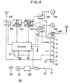
- a voltage V ACC from the hands-free accessory 200 is used to indicate whether or not the portable telephone 100 is connected to the hands-free accessory 200; however, alternatively a switch 199 mechanically switched ON and OFF when the connector plug 213 is plugged into and removed from the connector jack 113 may be provided, and whether or not the portable telephone 100 is connected to the hands-free accessory 200 may be detected from the output of this switch 199. This is shown Fig. 4.
- the portable telephone 100 is connected to the hands-free accessory 200 it is possible to change between the normal mode and the hands-free mode just by opening and closing the microphone arm 151. Furthermore, because this opening and closing of the microphone arm 151 is the same operation as when the portable telephone 100 is being used on its own, changing over between the normal mode and the hands-free mode can be carried out extremely naturally even when the portable telephone 100 is connected to the hands-free accessory 200.
Landscapes
- Engineering & Computer Science (AREA)
- Signal Processing (AREA)
- Mobile Radio Communication Systems (AREA)
- Telephone Set Structure (AREA)
Abstract
Description
- This invention relates to a communication apparatus, such as may include a portable telephone which can be used together with a hands-free accessory.
- One accessory for using a portable telephone inside a car is known as a hands-free accessory. When a hands-free accessory is provided in a car and a portable telephone is connected to this hands-free accessory, it is possible to switch between a microphone and a speaker built into the portable telephone and a microphone and a speaker mounted inside the car and it is possible to have hands-free telephone conversations.
- Also, when a portable telephone is used inside a car and the antenna of the portable telephone consequently becomes shielded by the body of the car, if the portable telephone is connected to a hands-free accessory the antenna of the portable telephone is connected to an external antenna mounted for example above the trunk of the car and as a result there is no loss of sensitivity of reception due to the shielding effect of the car body. Furthermore, because when a portable telephone is connected to hands-free accessory power is supplied to the portable telephone from a car battery, the portable telephone can be used for long periods.
- However, when a hands-free accessory is used to conduct a hands-free telephone conversation, the voice of the other party comes out of the speaker mounted inside the car. If there is another person in the car, this is sometimes inconvenient.
- To solve this problem, actual hands-free accessories are designed so that even when the portable telephone is connected to the hands-free accessory it is still possible to have a telephone conversation using the microphone and the speaker built into the portable telephone. That is, it is possible to selectively use either a hands-free mode wherein the speaker and microphone of the hands-free accessory are used or a normal mode wherein the speaker and microphone of the portable telephone are used.
- For switching between the hands-free mode and the normal mode there are mainly the following three methods:
- [1] Providing the hands-free accessory with a mode changeover switch.
- [2] Providing the portable telephone with a mode changeover switch.
- [3] Performing mode changeover using a function key of the portable telephone.
- However, in case [1] it is necessary for the hands-free accessory to inform the portable telephone of which is the current mode, and because for this an extra connection line between the hands-free accessory and the portable telephone is needed and a mode changeover switch is necessary, the cost of the equipment increases.
- In case [2] the portable telephone must be provided with an extra operating key, and because portable telephones are small and have small panel areas, this method causes key layout problems, and other keys have to be made smaller, which creates operatability problems. Furthermore, to a user who does not use a hands-free accessory a mode changeover key is useless.
- In case [3], because a function key and another operating key have to be pressed in order a key operation of two or more steps is necessary, and this is troublesome and operatability is impaired.
- According to the present invention there is provided a communication apparatus as defined in claim 1.
- The following non-limitative description is given by way of example. With reference to the accompanying drawings, in which :
- Fig. 1 is a perspective view of an embodiment of the invention;
- Fig. 2 is a system diagram of a portable telephone;
- Fig. 3 is a system diagram of an example of a hands-free accessory;
- Fig. 4 is a system diagram of a portable telephone; and
- Fig. 5 is a flow chart showing an operation of an embodiment of the invention.
- Fig. 1 shows the exterior of a
portable telephone 100 and a hands-free accessory 200 according to the invention. - A flat, rectangular boxlike
plastic case 141 constitutes the main body of theportable telephone 100; anantenna 105 for transmission and reception is mounted on the top of thecase 141 and aspeaker 102 andoperating keys 112 such as dialing keys are provided on the front of thecase 141. - A pull-out
microphone 101 is mounted on for example the right side surface of thecase 141. That is, atubular microphone arm 151 made of a plastic having some elasticity has a lower end pivotally attached by means of apivot mechanism 152 to the lower end of the right side surface of thecase 141 and themicrophone 101 is disposed inside the other end of thismicrophone arm 151. In this preferred embodiment, themicrophone arm 151 is pivotable in a plane including the right side surface of thecase 141 and also in front of thecase 141, as shown by thearrow 159. - Thus in a first state the
microphone arm 151 is retracted to along the right side surface of thecase 141 as shown with broken lines in Fig. 1 (the closed state of the microphone arm 151) and in a second state themicrophone arm 151 is pivotally pulled out to a position substantially 180° from the front surface of the case 141 (the open state of the microphone arm 151). The length of themicrophone arm 151 and its point of attachment to thecase 141 are so set that when themicrophone arm 151 has been pulled out to its open position the distance between themicrophone 101 and thespeaker 102 is about the same as that between the microphone and speaker of an ordinary telephone. - A
permanent magnet 153 is mounted inside the central portion of themicrophone arm 151, and aHall effect device 121 serving as a magnetic field sensing device is disposed inside thecase 141 in a position such that it faces thepermanent magnet 153 when themicrophone arm 151 is in its closed position (shown by the broken lines). - A
connector jack 113 for connecting a hands-free accessory 200 or the like to theportable telephone 100 is provided in the bottom of thecase 141, and although not shown in the drawings thisconnector jack 113 is covered by a cover when not being used. - The size of this
portable telephone 100 when themicrophone arm 151 is in its closed state is for example about 86mm (height) x 64mm (width) x 24mm (depth). - A
main unit 210 of the hands-free accessory 200 is disposed for example in a vehicle between a driver's seat and a passenger seat or under a dashboard. Aconnector plug 213 for being connected to theconnector jack 113 of theportable telephone 100 is connected to themain unit 210 by acurl cord 212. - A
microphone 201 and aspeaker 202 for hands-free use are connected to themain unit 210 by cords. Themicrophone 201 and thespeaker 202 may be mounted anywhere in the vehicle the user likes. - Also, an
external antenna 205 is connected to themain unit 210 by acoaxial cable 206. In this preferred embodiment, theexternal antenna 205 is for example mounted above the trunk of the vehicle. - Fig. 2 and Fig. 3 respectively show examples of circuits of the
portable telephone 100 and the hands-free accessory 200. - In the
portable telephone 100 circuit shown in Fig. 2, a baseband signal processor 103 processes for transmission or reception bass band signals such as voice or data signals and anRF signal processor 104 transmits or receives these bass band signals. Switchingcircuits 106 to 108 are for switching theportable telephone 100 between a normal mode and a hands-free mode. - A
controller 111 for system control controls the channels used by theRF signal processor 104 and transmission and reception thereof and carries out control of the baseband signal processor 103 and accessing of data through the baseband signal processor 103. Thecontroller 111 also controls theswitching circuits 106 to 108. Output of theoperating keys 112 is fed to thecontroller 111. - The
connector jack 113 has contacts A to F, and these contacts A to F are severally connected to the circuits. The output signal of theHall effect device 121 is fed to thecontroller 111 through a rectifyingcircuit 122. The output voltage of an internalrechargeable battery 131 is supplied to each of the various circuits. - As will be discussed in detail later, when this
portable telephone 100 is connected to the hands-free accessory 200, a voltage VACC of a predetermined level is supplied to the contact C of theconnector jack 113, and thecontroller 111 determines whether or not theportable telephone 100 is connected to the hands-free accessory 200 by means of this voltage VACC. - In the hands-
free accessory 200 circuit shown in Fig. 3,VOX switching circuits detector circuits voltage comparator circuit 223 are connected to voice signal lines of themain unit 210. - In this preferred embodiment, the
detector circuit 221 detects the level of a voice signal from themicrophone 201 and outputs a direct current voltage of a level corresponding to the level of this voice signal. Thedetector circuit 222 similarly detects the level of a voice signal supplied to thespeaker 202 and outputs a direct current voltage of a level corresponding to the level of that voice signal. - The output voltages of these
detector circuits voltage comparator circuit 223. Outputs of thevoltage comparator circuit 223 of opposite phase are supplied to theswitching circuits - A voltage regulator 231 is also provided in the
main unit 210. An output voltage of acar battery 209 is supplied to the voltage regulator 231 and a stabilized output voltage of the voltage regulator 231 is supplied as an operating voltage to the circuits of themain unit 210 and is outputted through thecurl cord 212 to theconnector plug 213. Although not shown in the drawings, theconnector plug 213 has contacts which are severally connected to the contacts A to F of theconnector jack 113. - The predetermined voltage VACC is produced by
resistors curl cord 212 to theconnector plug 213. - With this construction, when the
microphone arm 151 is in its closed position as shown by the broken line in Fig. 1 thepermanent magnet 153 faces theHall effect device 121 and when themicrophone arm 151 is in its open position as shown with solid lines in Fig. 1 thepermanent magnet 153 does not face theHall effect device 121. As a result, by checking the output signal of the rectifyingcircuit 122, thecontroller 111 can detect whether themicrophone arm 151 is in its closed position or in its open position. - When the
connector plug 213 is connected to theconnector jack 113, the voltage VACC from theresistors connector plug 213 to the contact C of theconnector jack 113. However, when theconnector plug 213 is not connected to theconnector jack 113, no voltage is fed to the contact C of theconnector jack 113. As a result, by checking the voltage level of the contact C of theconnector jack 113, thecontroller 111 can detect whether or not the hands-free accessory 200 is connected to theportable telephone 100 or whether theportable telephone 100 is on its own. - The following kinds of operation are performed with respect to the above detection results. These operations are shown in the flow chart of Fig. 5. The following description is divided into a description of a case wherein the
portable telephone 100 is used on its own and a description of a case wherein the hands-free accessory 200 is used; however, the actual operation of the device is as shown in the flow chart.
1 When thePortable Telephone 100 is Used On Its Own
1-1 When theMicrophone Arm 151 is in its Closed Position - In this case, the switching
circuits 106 to 108 are put by thecontroller 111 into for example the states in which they are shown in Fig. 2. - When a power switch of the
portable telephone 100 is turned ON, theportable telephone 100 goes into a waiting mode. That is, in this case, theRF signal processor 104, the baseband signal processor 103 and part of thecontroller 111 are activated and theportable telephone 100 is able to respond to an incoming call request or the like from a portable telephone base station. - However, if an operating
key 112 is depressed, the key output is ignored. As a result, when theportable telephone 100 is in a bag or a pocket or the like, even if a key 112 is accidently depressed, that key operation is ineffective; in other words, a failsafe function is in operation.
1-2 When theMicrophone Arm 151 is in its Open Position - In this case also the switching
circuits 106 to 108 are put by thecontroller 111 into the states in which they are shown in Fig. 2. - By the
microphone arm 151 being opened, theportable telephone 100 is rendered usable. That is, when from the waiting mode themicrophone arm 151 is opened, operation of thekeys 112 becomes effective and it is possible for example to make a call. - When the
microphone arm 151 is opened because there is an incoming call while theportable telephone 100 is in the waiting mode, a connection protocol is executed with respect to the incoming call and theportable telephone 100 is connected to the caller via the base station. - During an outgoing or incoming call, a user's voice signal is fed from the
microphone 101 through theswitching circuit 106 to the baseband signal processor 103 where it undergoes transmission processing. This processed voice signal is then fed to theRF signal processor 104 and turned into an outward channel transmission signal, and this transmission signal is fed through theswitching circuit 108 to theantenna 105 and transmitted to the base station. - A signal transmitted from the base station on an inward channel is received by the
antenna 105, this received signal is fed through theswitching circuit 108 to theRF signal processor 104 where a voice signal of the other party is extracted from it, and this voice signal is fed to the baseband signal processor 103 where it undergoes reception processing. This processed voice signal is then fed through theswitching circuit 107 to thespeaker 102. - Thus, when the
portable telephone 100 is on its own, it can be used in the same way as an ordinary portable telephone. Furthermore, it has a failsafe function with respect to the operatingkeys 112.
2 When thePortable Telephone 100 is Connected to the Hands-free Accessory 200
2-1 When theMicrophone Arm 151 is in its Closed Position - In this case, the switching
circuits 106 to 108 are put by thecontroller 111 into states the reverse of those in which they are shown in Fig. 2. - The output voltage of the
car battery 209 is fed through the voltage regulator 231, thecurl cord 212, theconnector plug 213 and the contact D of theconnector jack 113 to theportable telephone 100 and to the circuits of theportable telephone 100 as an operating voltage thereof, and therechargeable battery 131 is charged. - During a call, a voice signal of the user is fed through the
microphone 201, theswitching circuit 214, theconnector plug 213, the contact A of theconnector jack 113 and theswitching circuit 106 to the baseband signal processor 103, whereafter in the same way as when theportable telephone 100 is on its own this voice signal is turned into an outward channel transmission signal and outputted by theRF signal processor 104. - The transmission signal from the
RF signal processor 104 then passes through theswitching circuit 108, the contact E of theconnector jack 113, theconnector plug 213, thecurl cord 212, an internal wire of themain unit 210 and thecoaxial cable 206 to theexternal antenna 205 and is transmitted to the base station. - A signal transmitted from the base station on an inward channel is received by the
external antenna 205, and in the reverse of the above is fed through thecoaxial cable 206, an internal wire of themain unit 210, thecurl cord 212, theconnector plug 213, the contact E of theconnector jack 113 and theswitching circuit 108 to theRF signal processor 104, whereafter a voice signal of the other party is outputted by the baseband signal processor 103. This voice signal is then fed through theswitching circuit 107, the contact B of theconnector jack 113, theconnector plug 213, thecurl cord 212 and theswitching circuit 215 to thespeaker 202. - However, in this case, when both the
microphone 201 and thespeaker 202 are simultaneously active, howling and echo occur. To avoid this, in this example, the level of the user's voice signal and the level of the other party's voice signal are compared by thevoltage comparator circuit 223, the switchingcircuits voltage comparator circuit 223, and of the switchingcircuits - In this way, hands-free dialogue is made possible.
2-2 When theMicrophone Arm 151 is in its Open Position - For example when the user does not want the content of a conversation to be heard, the user pulls down the
microphone arm 151 to its open position. When this is done, the switchingcircuits controller 111 into the states in which they are shown in Fig. 2 and theswitching circuit 108 is put into the opposite state to that in which it is shown in Fig. 2. - As a result, in this case, as described above under heading 1-2, the
microphone 101 and thespeaker 102 can be used and the content of the conversation, and particularly the voice of the other party, is not heard by other people in the vehicle. - In this case, because the
switching circuit 108 is in the opposite state to that in which it is shown in Fig. 2, transmission of waves to the base station is carried out using theexternal antenna 205 as described under heading 2-1. - The flow chart of Fig. 5 will now be explained.
- First, in
step 301, it is determined whether or not themicrophone arm 151 has been pulled out. If it has not been pulled out, processing proceeds to step 302. Instep 302, it is determined whether or not the hands-free accessory 200 has been connected to theportable telephone 100. If it has not been connected, processing proceeds to step 303. Step 303 is the waiting mode wherein key inputs are ignored, as shown insteps - When in
step 302 it is determined that the hands-free accessory 200 is connected to theportable telephone 100, processing proceeds to step 307. Instep 307, themicrophone 201 and thespeaker 202 are selected. Insteps portable telephone 100 goes into the normal mode and calling and receiving are carried out. - When on the other hand in
step 301 it is determined that themicrophone arm 151 has been pulled out, processing proceeds immediately to step 306 and themicrophone 101 and thespeaker 102 built into theportable telephone 100 itself are used. Theportable telephone 100 then goes into the normal mode insteps - When this is finished processing proceeds to step 310 and it is determined whether or not the power switch is OFF. When it is OFF, all processing is halted and when it is ON processing is repeated from the beginning.
- As described above, this
portable telephone 100 can be used on its own or connected to the hands-free accessory 200, and even when theportable telephone 100 is connected to the hands-free accessory 200 it is possible to change between the normal mode and the hands-free mode just by opening and closing themicrophone arm 151. Furthermore, because this opening and closing of themicrophone arm 151 is the same operation as when theportable telephone 100 is being used on its own, changing over between the normal mode and the hands-free mode can be carried out extremely naturally even when theportable telephone 100 is connected to the hands-free accessory 200. - Also, it is not necessary to provide the hands-
free accessory 200 with a switch for changing between modes as it is in the case [1] mentioned above in connection with the background of the invention, and therefore there is the cost merit that there is no need to increase the number of connecting lines or the number of contacts of theconnectors - Furthermore, because it is not necessary to increase the number of
operating keys 112 of theportable telephone 100 as it is in the case [2] mentioned above, there is no need to impair the operatability of theportable telephone 100 by changing the key layout or the sizes of the keys. Therefore, no problems are suffered by users who do not use a hands-free accessory 200. Also, because it is not necessary to push function keys or the like in two or more steps as it is in the case [3] mentioned above, the operatability of theportable telephone 100 is improved. - In the preferred embodiment described above, a voltage VACC from the hands-
free accessory 200 is used to indicate whether or not theportable telephone 100 is connected to the hands-free accessory 200; however, alternatively aswitch 199 mechanically switched ON and OFF when theconnector plug 213 is plugged into and removed from theconnector jack 113 may be provided, and whether or not theportable telephone 100 is connected to the hands-free accessory 200 may be detected from the output of thisswitch 199. This is shown Fig. 4. - According to the invention, even when the
portable telephone 100 is connected to the hands-free accessory 200 it is possible to change between the normal mode and the hands-free mode just by opening and closing themicrophone arm 151. Furthermore, because this opening and closing of themicrophone arm 151 is the same operation as when theportable telephone 100 is being used on its own, changing over between the normal mode and the hands-free mode can be carried out extremely naturally even when theportable telephone 100 is connected to the hands-free accessory 200. - Also, it is not necessary to provide the hands-
free accessory 200 with a switch for changing between modes as it is in the case [1] mentioned above in connection with the background of the invention, and therefore there is the cost benefit that there is no need to increase the number of connecting lines or the number of contacts of theconnectors - Furthermore, because it is not necessary to increase the number of
operating keys 112 of theportable telephone 100 as it is in the case [2] mentioned above, there is no need to impair the operatability of theportable telephone 100 by changing the key layout or the sizes of the keys. Therefore, no problems are suffered by users who do not use a hands-free accessory 200. Also, because it is not necessary to push function keys or the like in two or more steps as it is in the case [3] mentioned above, the operatability of theportable telephone 100 is improved.
Claims (16)
- A communication apparatus comprising:a first microphone (101) activated in a first mode;a first speaker (102) activated in a first mode;a second microphone (201) activated in a second mode;a second speaker (202) activated in a second mode; andmode determining means (111) determining whether the apparatus is in said first mode or said second mode.
- A communication apparatus comprising:a first microphone (101) activated in a first mode;a first speaker (102) activated in a first mode;an arm (151) having said first microphone (101), the position of the arm being changeable from a first position to a second position;position detection means (121) for detecting a position of said arm;a second microphone activated in a second mode;a second speaker activated in a second mode;switch means (106-108) for changing said first microphone and speaker to said second microphone and speaker according to said first mode and said second mode; andcontrol means (111) for determining whether a status of the apparatus is said first mode or said second mode.
- A communication apparatus according to claim 2, wherein said arm position is changeable by rotation of the arm (151) around a predetermined axis.
- A communication apparatus according to claim 2 or 3, further comprising a magnet (153) located at a predetermined position of said arm (151), wherein said position detection means is a magnetic field detection means (121) located at a corresponding position to said magnet when said arm is in said first position.
- A communication apparatus according to any one of claims 2 to 4, further comprising :a telephone apparatus (100) including said first microphone (101), said first speaker (102), said arm (151) and said position detection means (121);an accessory apparatus (200) connected to said telephone apparatus (100), including said second microphone (201) and said second speaker (202); andaccessory connecting detection means (111) for detecting whether said accessory apparatus is connected to said telephone apparatus.
- A communication apparatus according to claim 5, wherein said accessory connecting detection means (111) detects a predetermined voltage (VACC) which is supplied from said accessory apparatus (200) to said telephone apparatus (100).
- A communication apparatus according to claim 5 or 6, wherein said accessory connecting detection means (111) detects mechanically a connecting status of a connector from said accessory apparatus to said telephone apparatus.
- A telephone apparatus (100) comprising:a microphone (101) activated in a first mode;a speaker (102) activated in a first mode;an arm (151) having said microphone (101), the position of the arm being changeable from a first position to a second position;position detection means (121) for detecting a position of said arm;switch means (106-108) for switching a status of use or non-use of said microphone and speaker according to said first mode, andcontrol means (111) for determining whether a status of an apparatus is said first mode or not.
- A telephone apparatus according to claim 8, wherein said arm position is changeable by rotation of the arm (151) around a predetermined axis.
- A telephone apparatus according to claim 8 or 9, wherein:a magnet (153) is located at a predetermined position of said arm; andsaid position detection means is a magnetic field detection means (121) located at a corresponding position to said magnet when said arm (151) is in said first position.
- A telephone apparatus according to claim 6, further comprising accessory connecting detection means (111) for detecting whether an accessory apparatus (200) is connected to said telephone apparatus (100), wherein said control means (111) determines whether a status of said telephone apparatus (100) is said first mode or not by using an output signal of said accessory connecting detection means (111).
- An accessory apparatus (200) comprising:a microphone (201) activated in a predetermined mode;a speaker (202) activated in a predetermined mode; andconnector means (213) for connecting to a telephone apparatus (100) for transmitting and receiving audio signals and supplying power.
- A method of communication comprising steps of :a mode determining step which determines whether it uses a first set of a microphone and a speaker or a second set of a microphone and a speaker;a selecting step selecting said first or second set of a microphone and a speaker according to said determined mode; anda communicating step communicating in a predetermined manner.
- A method of communication as claimed in claim 13 wherein said mode determining step detects a status of a microphone arm.
- A method of communication according to claim 14, further comprising the step of, after said step of detecting a status of a microphone arm, detecting a connection status of an accessory apparatus to a telephone apparatus.
- A method of communication according to claim 15, further comprising the step of, after said step detecting the connection status of an accessory apparatus, if it is not connected, the apparatus operating in a waiting mode.
Applications Claiming Priority (2)
| Application Number | Priority Date | Filing Date | Title |
|---|---|---|---|
| JP298914/94 | 1994-11-08 | ||
| JP29891494A JP3360703B2 (en) | 1994-11-08 | 1994-11-08 | Mobile phone |
Publications (2)
| Publication Number | Publication Date |
|---|---|
| EP0712225A2 true EP0712225A2 (en) | 1996-05-15 |
| EP0712225A3 EP0712225A3 (en) | 1998-06-24 |
Family
ID=17865813
Family Applications (1)
| Application Number | Title | Priority Date | Filing Date |
|---|---|---|---|
| EP95307931A Withdrawn EP0712225A3 (en) | 1994-11-08 | 1995-11-07 | Portable telephone with a hands-free accessory |
Country Status (4)
| Country | Link |
|---|---|
| US (1) | US5749057A (en) |
| EP (1) | EP0712225A3 (en) |
| JP (1) | JP3360703B2 (en) |
| SG (1) | SG46959A1 (en) |
Families Citing this family (23)
| Publication number | Priority date | Publication date | Assignee | Title |
|---|---|---|---|---|
| US5991646A (en) * | 1997-10-08 | 1999-11-23 | Sony Corporation | Articulating speaker and microphone for a wireless telephone with cigarette lighter adapter |
| US6002949A (en) * | 1997-11-18 | 1999-12-14 | Nortel Networks Corporation | Handset with a single transducer for handset and handsfree functionality |
| US6058184A (en) * | 1997-12-17 | 2000-05-02 | Sony Corporation Of Japan | Speaker unit with boom microphone |
| USD406587S (en) * | 1998-04-06 | 1999-03-09 | Sony Corporation | Cellular telephone with fold-out keyboard |
| USD424051S (en) * | 1998-05-28 | 2000-05-02 | Sony Corporation | Cellular telephone with pivotally extendible grip |
| KR100481845B1 (en) * | 1998-06-10 | 2005-06-08 | 삼성전자주식회사 | Portable computer having a microphone |
| US6266542B1 (en) * | 1998-09-24 | 2001-07-24 | Ericsson Inc. | Accessory allowing hands-free operation of a cellular telephone |
| US6512826B1 (en) * | 1998-11-30 | 2003-01-28 | Westech Korea Inc. | Multi-directional hand-free kit |
| TW472992U (en) * | 1999-02-01 | 2002-01-11 | Cotron Corp | Transferring device for telephone |
| USD424555S (en) * | 1999-03-17 | 2000-05-09 | Sony Corporation | Cellular telephone with pivotable belt clip/antenna |
| USD434403S (en) * | 2000-02-02 | 2000-11-28 | Sony Corporation | Cellular telephone handset |
| FR2807261B1 (en) * | 2000-04-03 | 2002-05-17 | Raoul Girod | HANDSFREE FILTERING SYSTEM FOR RADIOTELEPHONES |
| JP4675458B2 (en) * | 2000-06-28 | 2011-04-20 | 京セラ株式会社 | Hands-free device |
| US20020068617A1 (en) * | 2000-12-02 | 2002-06-06 | Han Kim Kyu | Hands free apparatus |
| US6678536B2 (en) | 2000-12-07 | 2004-01-13 | Mark Wendell Fletcher | Wireless microphone |
| US6542757B2 (en) * | 2001-01-11 | 2003-04-01 | Youngbo Engineering, Inc. | Headset docking device |
| US20040248623A1 (en) * | 2001-05-22 | 2004-12-09 | Safco Corporation | Hands free accessory for wireless telephones |
| US6836676B2 (en) * | 2001-11-02 | 2004-12-28 | Motorola, Inc. | Speakerphone accessory |
| US6957090B2 (en) * | 2002-03-08 | 2005-10-18 | Kyocera Wireless Corp. | Hands-free car kit |
| US7343174B2 (en) * | 2003-04-23 | 2008-03-11 | At&T Knowledge Ventures, L.P. | Wireless electronic drive-thru system and method |
| US20090197649A1 (en) * | 2008-02-05 | 2009-08-06 | Rebelvox, Llc | Mobile phone with headset docking station |
| JP5455788B2 (en) * | 2010-05-27 | 2014-03-26 | 富士フイルム株式会社 | Diagnostic equipment system |
| JP6206103B2 (en) * | 2013-11-07 | 2017-10-04 | アイコム株式会社 | Voice communication terminal device |
Family Cites Families (18)
| Publication number | Priority date | Publication date | Assignee | Title |
|---|---|---|---|---|
| US4056696A (en) * | 1976-09-15 | 1977-11-01 | Bell Telephone Laboratories, Incorporated | Flat panel telephone station set |
| US4878237A (en) * | 1988-11-23 | 1989-10-31 | Cianflone Stephen P | Shoulder cradle for supporting a cellular car phone |
| US5212722A (en) * | 1989-07-24 | 1993-05-18 | Nec Corporation | Hands-free telephone having a handset volume attenuator for controlling speaker volume in a hands-free adaptor |
| US5261121A (en) * | 1989-08-11 | 1993-11-09 | Nec Corporation | Portable radio transceiver system having improved adaptor and/or improved receiver signal control arrangement |
| US5175759A (en) * | 1989-11-20 | 1992-12-29 | Metroka Michael P | Communications device with movable element control interface |
| DE9005989U1 (en) * | 1990-05-26 | 1990-08-02 | Votronic Entwicklungs- Und Produktionsgesellschaft Fuer Elektronische Geraete Mbh, 6670 St Ingbert | Hearing and speaking unit for mobile telephones installed in motor vehicles |
| EP0494780B1 (en) * | 1991-01-11 | 1997-03-26 | Kabushiki Kaisha Toshiba | An adapter unit for adaptively supplying a portable radio telephone with power |
| US5659887A (en) * | 1991-06-15 | 1997-08-19 | Kabushiki Kaisha Honda Access | Portable radiotelephone and holder for mounting within a vehicle |
| US5282246A (en) * | 1991-11-08 | 1994-01-25 | Yang Chao Ming | Handsfree mobile telephone rack |
| DE4207507A1 (en) * | 1992-03-10 | 1993-09-16 | Philips Patentverwaltung | MESSAGE DEVICE WITH A HANDS-FREE UNIT |
| JPH06102890A (en) * | 1992-09-22 | 1994-04-15 | Pioneer Electron Corp | Karaoke system |
| FR2706103B1 (en) * | 1993-06-03 | 1997-01-31 | Ericsson Ge Mobile Communicat | Radiotelephone apparatus. |
| US5557653A (en) * | 1993-07-27 | 1996-09-17 | Spectralink Corporation | Headset for hands-free wireless telephone |
| FR2711872B1 (en) * | 1993-10-21 | 1996-02-09 | Jean Pierre Talvard | Independent portable device forming directory and telephone dialer. |
| FI107002B (en) * | 1994-01-13 | 2001-05-15 | Nokia Mobile Phones Ltd | Hands free or HF device for mobile phone |
| TW367687B (en) * | 1994-08-09 | 1999-08-21 | At & T Corp | Telephone handset |
| US5504812A (en) * | 1994-10-11 | 1996-04-02 | Motorola, Inc. | Headset for use with a radiotelephone |
| US5490213A (en) * | 1994-11-28 | 1996-02-06 | Huang; Lin-Wei | Apparatus for hands-free operation of a mobile telephone unit in a car |
-
1994
- 1994-11-08 JP JP29891494A patent/JP3360703B2/en not_active Expired - Fee Related
-
1995
- 1995-11-03 US US08/552,864 patent/US5749057A/en not_active Expired - Fee Related
- 1995-11-07 EP EP95307931A patent/EP0712225A3/en not_active Withdrawn
- 1995-11-08 SG SG1995001762A patent/SG46959A1/en unknown
Non-Patent Citations (1)
| Title |
|---|
| None |
Also Published As
| Publication number | Publication date |
|---|---|
| JP3360703B2 (en) | 2002-12-24 |
| US5749057A (en) | 1998-05-05 |
| EP0712225A3 (en) | 1998-06-24 |
| SG46959A1 (en) | 1998-03-20 |
| JPH08140129A (en) | 1996-05-31 |
Similar Documents
| Publication | Publication Date | Title |
|---|---|---|
| US5749057A (en) | Telephone handset for hands-free use in an auto mobile | |
| US5991640A (en) | Docking and electrical interface for personal use communication devices | |
| CA2165020C (en) | Cellular speakerphone and method of operation thereof | |
| US4647722A (en) | Land mobile telephone system | |
| US5442814A (en) | Cellular telephone facilitating a response holding state | |
| US6330457B1 (en) | Telephone call service by sensing hand-held state of cellular telephone | |
| US6226529B1 (en) | System for providing a simultaneous data and voice channel within a single channel of a portable cellular telephone to provide position-enhanced cellular services (PECS) | |
| US5610971A (en) | Dual keypad telephone handset for mobile communications | |
| US6285890B1 (en) | Automatic sensing of communication or accessories for mobile terminals | |
| GB2329773A (en) | Car audio equipment with cellphone | |
| EP0483956A2 (en) | Combined broadcast radio receiver and radio telephone | |
| KR19990062481A (en) | Speaker unit with boom microphone | |
| EP0393059A1 (en) | Method for terminating a telephone call by voice command. | |
| JPH11163989A (en) | Portable telephone set | |
| CA2033270C (en) | Radio communication apparatus for a selected one of a plurality of terminal units of different kinds | |
| US6230030B1 (en) | Hands-free switching device for use with a mobile telephone in a car | |
| KR20050120390A (en) | Speaker phone control apparatus and method for mobile station using proximity sensor | |
| US8032076B2 (en) | Cellular telephone and multimedia accessory audio system adaptor and methods therefor | |
| GB2420930A (en) | Auxiliary handset accessory kit and method for a radio telephoe in a vehicle | |
| KR950004457Y1 (en) | Telephone adaptor | |
| KR100548398B1 (en) | Speaker apparatus in mobile phone | |
| JPH0371819B2 (en) | ||
| JPH10200616A (en) | Portable telephone set operating device | |
| JP2002142007A (en) | Hands-free speech device for automobile | |
| JPH09139765A (en) | Onboard speech structure for portable telephone set |
Legal Events
| Date | Code | Title | Description |
|---|---|---|---|
| PUAI | Public reference made under article 153(3) epc to a published international application that has entered the european phase |
Free format text: ORIGINAL CODE: 0009012 |
|
| AK | Designated contracting states |
Kind code of ref document: A2 Designated state(s): DE FR GB |
|
| PUAL | Search report despatched |
Free format text: ORIGINAL CODE: 0009013 |
|
| AK | Designated contracting states |
Kind code of ref document: A3 Designated state(s): DE FR GB |
|
| 17P | Request for examination filed |
Effective date: 19981203 |
|
| 17Q | First examination report despatched |
Effective date: 20010531 |
|
| STAA | Information on the status of an ep patent application or granted ep patent |
Free format text: STATUS: THE APPLICATION IS DEEMED TO BE WITHDRAWN |
|
| 18D | Application deemed to be withdrawn |
Effective date: 20011011 |