EP0711569A1 - Means and method for determining the level of removed ureminatoxins during a dialysis treatment - Google Patents
Means and method for determining the level of removed ureminatoxins during a dialysis treatment Download PDFInfo
- Publication number
- EP0711569A1 EP0711569A1 EP95117313A EP95117313A EP0711569A1 EP 0711569 A1 EP0711569 A1 EP 0711569A1 EP 95117313 A EP95117313 A EP 95117313A EP 95117313 A EP95117313 A EP 95117313A EP 0711569 A1 EP0711569 A1 EP 0711569A1
- Authority
- EP
- European Patent Office
- Prior art keywords
- valve
- sampling
- hemodialysis machine
- dialysate
- outlet
- Prior art date
- Legal status (The legal status is an assumption and is not a legal conclusion. Google has not performed a legal analysis and makes no representation as to the accuracy of the status listed.)
- Granted
Links
Images

Classifications
-
- A—HUMAN NECESSITIES
- A61—MEDICAL OR VETERINARY SCIENCE; HYGIENE
- A61M—DEVICES FOR INTRODUCING MEDIA INTO, OR ONTO, THE BODY; DEVICES FOR TRANSDUCING BODY MEDIA OR FOR TAKING MEDIA FROM THE BODY; DEVICES FOR PRODUCING OR ENDING SLEEP OR STUPOR
- A61M1/00—Suction or pumping devices for medical purposes; Devices for carrying-off, for treatment of, or for carrying-over, body-liquids; Drainage systems
- A61M1/14—Dialysis systems; Artificial kidneys; Blood oxygenators ; Reciprocating systems for treatment of body fluids, e.g. single needle systems for hemofiltration or pheresis
- A61M1/16—Dialysis systems; Artificial kidneys; Blood oxygenators ; Reciprocating systems for treatment of body fluids, e.g. single needle systems for hemofiltration or pheresis with membranes
- A61M1/1601—Control or regulation
- A61M1/1619—Sampled collection of used dialysate, i.e. obviating the need for recovery of whole dialysate quantity for post-dialysis analysis
-
- A—HUMAN NECESSITIES
- A61—MEDICAL OR VETERINARY SCIENCE; HYGIENE
- A61M—DEVICES FOR INTRODUCING MEDIA INTO, OR ONTO, THE BODY; DEVICES FOR TRANSDUCING BODY MEDIA OR FOR TAKING MEDIA FROM THE BODY; DEVICES FOR PRODUCING OR ENDING SLEEP OR STUPOR
- A61M1/00—Suction or pumping devices for medical purposes; Devices for carrying-off, for treatment of, or for carrying-over, body-liquids; Drainage systems
- A61M1/14—Dialysis systems; Artificial kidneys; Blood oxygenators ; Reciprocating systems for treatment of body fluids, e.g. single needle systems for hemofiltration or pheresis
- A61M1/16—Dialysis systems; Artificial kidneys; Blood oxygenators ; Reciprocating systems for treatment of body fluids, e.g. single needle systems for hemofiltration or pheresis with membranes
- A61M1/168—Sterilisation or cleaning before or after use
- A61M1/1682—Sterilisation or cleaning before or after use both machine and membrane module, i.e. also the module blood side
-
- A—HUMAN NECESSITIES
- A61—MEDICAL OR VETERINARY SCIENCE; HYGIENE
- A61M—DEVICES FOR INTRODUCING MEDIA INTO, OR ONTO, THE BODY; DEVICES FOR TRANSDUCING BODY MEDIA OR FOR TAKING MEDIA FROM THE BODY; DEVICES FOR PRODUCING OR ENDING SLEEP OR STUPOR
- A61M1/00—Suction or pumping devices for medical purposes; Devices for carrying-off, for treatment of, or for carrying-over, body-liquids; Drainage systems
- A61M1/14—Dialysis systems; Artificial kidneys; Blood oxygenators ; Reciprocating systems for treatment of body fluids, e.g. single needle systems for hemofiltration or pheresis
- A61M1/16—Dialysis systems; Artificial kidneys; Blood oxygenators ; Reciprocating systems for treatment of body fluids, e.g. single needle systems for hemofiltration or pheresis with membranes
- A61M1/168—Sterilisation or cleaning before or after use
- A61M1/1688—Sterilisation or cleaning before or after use with recirculation of the sterilising fluid
-
- A—HUMAN NECESSITIES
- A61—MEDICAL OR VETERINARY SCIENCE; HYGIENE
- A61M—DEVICES FOR INTRODUCING MEDIA INTO, OR ONTO, THE BODY; DEVICES FOR TRANSDUCING BODY MEDIA OR FOR TAKING MEDIA FROM THE BODY; DEVICES FOR PRODUCING OR ENDING SLEEP OR STUPOR
- A61M1/00—Suction or pumping devices for medical purposes; Devices for carrying-off, for treatment of, or for carrying-over, body-liquids; Drainage systems
- A61M1/36—Other treatment of blood in a by-pass of the natural circulatory system, e.g. temperature adaptation, irradiation ; Extra-corporeal blood circuits
- A61M1/3607—Regulation parameters
- A61M1/3609—Physical characteristics of the blood, e.g. haematocrit, urea
- A61M1/3612—Physical characteristics of the blood, e.g. haematocrit, urea after treatment
-
- A—HUMAN NECESSITIES
- A61—MEDICAL OR VETERINARY SCIENCE; HYGIENE
- A61M—DEVICES FOR INTRODUCING MEDIA INTO, OR ONTO, THE BODY; DEVICES FOR TRANSDUCING BODY MEDIA OR FOR TAKING MEDIA FROM THE BODY; DEVICES FOR PRODUCING OR ENDING SLEEP OR STUPOR
- A61M1/00—Suction or pumping devices for medical purposes; Devices for carrying-off, for treatment of, or for carrying-over, body-liquids; Drainage systems
- A61M1/36—Other treatment of blood in a by-pass of the natural circulatory system, e.g. temperature adaptation, irradiation ; Extra-corporeal blood circuits
- A61M1/3621—Extra-corporeal blood circuits
- A61M1/3643—Priming, rinsing before or after use
- A61M1/3644—Mode of operation
- A61M1/3647—Mode of operation with recirculation of the priming solution
-
- A—HUMAN NECESSITIES
- A61—MEDICAL OR VETERINARY SCIENCE; HYGIENE
- A61M—DEVICES FOR INTRODUCING MEDIA INTO, OR ONTO, THE BODY; DEVICES FOR TRANSDUCING BODY MEDIA OR FOR TAKING MEDIA FROM THE BODY; DEVICES FOR PRODUCING OR ENDING SLEEP OR STUPOR
- A61M1/00—Suction or pumping devices for medical purposes; Devices for carrying-off, for treatment of, or for carrying-over, body-liquids; Drainage systems
- A61M1/14—Dialysis systems; Artificial kidneys; Blood oxygenators ; Reciprocating systems for treatment of body fluids, e.g. single needle systems for hemofiltration or pheresis
- A61M1/16—Dialysis systems; Artificial kidneys; Blood oxygenators ; Reciprocating systems for treatment of body fluids, e.g. single needle systems for hemofiltration or pheresis with membranes
- A61M1/168—Sterilisation or cleaning before or after use
-
- A—HUMAN NECESSITIES
- A61—MEDICAL OR VETERINARY SCIENCE; HYGIENE
- A61M—DEVICES FOR INTRODUCING MEDIA INTO, OR ONTO, THE BODY; DEVICES FOR TRANSDUCING BODY MEDIA OR FOR TAKING MEDIA FROM THE BODY; DEVICES FOR PRODUCING OR ENDING SLEEP OR STUPOR
- A61M2205/00—General characteristics of the apparatus
- A61M2205/33—Controlling, regulating or measuring
- A61M2205/3331—Pressure; Flow
- A61M2205/3334—Measuring or controlling the flow rate
-
- Y—GENERAL TAGGING OF NEW TECHNOLOGICAL DEVELOPMENTS; GENERAL TAGGING OF CROSS-SECTIONAL TECHNOLOGIES SPANNING OVER SEVERAL SECTIONS OF THE IPC; TECHNICAL SUBJECTS COVERED BY FORMER USPC CROSS-REFERENCE ART COLLECTIONS [XRACs] AND DIGESTS
- Y10—TECHNICAL SUBJECTS COVERED BY FORMER USPC
- Y10S—TECHNICAL SUBJECTS COVERED BY FORMER USPC CROSS-REFERENCE ART COLLECTIONS [XRACs] AND DIGESTS
- Y10S210/00—Liquid purification or separation
- Y10S210/929—Hemoultrafiltrate volume measurement or control processes
Definitions
- the invention relates to a device and a method for determining the effectiveness of a hemodialysis treatment or of the uremia toxins removed during a hemodialysis treatment.
- Chronic hemodialysis treatment is the most common kidney replacement therapy. Approximately 500,000 patients live with this therapy because they have no better alternatives, such as the transplantation of carcasses. The total cost of treatment, which amounts to approximately US $ 50,000 per patient per year, has put enormous strain on health insurance and the health system. Only a part of the costs is directly caused by the hemodialysis treatment, the greater part falls on other treatments, hospital stays, blood connection problems and transport to the dialysis station. However, the pressure to save costs affects the actual dialysis treatment, since this is schematic and is carried out by large organizations.
- the object of this invention is to provide a device and a method that with Minimal hardware expenditure in the dialysis machine enables the amount of uremia toxins removed to be determined without requiring blood samples.
- Another object of this invention is to provide a method of sterilizing a dialysis machine so that the result of detecting the amount of uremia toxins is not affected by bacterial contamination.
- a recognized method for assessing the effectiveness of dialysis is urea kinetics.
- the reduction in the plasma concentration of urea from the beginning to the end of hemodialysis is used as a measure of the effectiveness. It is generally known that urea is not acutely toxic and in this case is only used as a reference substance for the measurement.
- the urea kinetic method is described in detail, for example, in the work of: "Sargent JA, Gotch FA. Principles and Biophysics of Dialysis. Maher JF, editors. Replacement of Renal Function by Dialysis, 3rd ed .. Kluwer Academic Publishers, 1989: 87-143" .
- the standard method assumes an even distribution of urea in the whole body water and is therefore called a 1-pool model.
- a complete measurement includes at least three blood samples. One each at the beginning and end of one treatment and another one before the start of the next.
- the urea concentration drops exponentially during dialysis. From the two first urea measurements mentioned at the beginning and end of the dialysis, the exponential coefficient of this waste can be calculated by K * T / V is characterized.
- K is the effective urea clearance, T the dialysis time and V the urea distribution volume, usually equated with whole-body water. Clinical observation has shown that KT / V must be at least 1.
- the amount of urea produced by the metabolism can be determined from the second and third measurement of the series of measurements described, from which, as described in "Replacement of Renal Function by Dialysis", the amount of protein converted (protein catabolic rate) is calculated can be. This is important because it has been found that the probability of survival depends very much on the plasma albumin content and this in turn depends on the protein intake.
- Both methods have the disadvantage of taking the sample from an area of the hydraulic system which is usually bacterially contaminated and is never disinfected or sterilized in devices whose sterilization or disinfection takes place in recirculation.
- Hemodialysis machines need to be disinfected from time to time, usually at least once a day. They are continually contaminated: by non-sterile water, non-sterile dialysis concentrate, but also by the connection procedure of dialyzers, which is usually not aseptic on the dialysis fluid side.
- disinfection is carried out by heating the inflowing water to more than 85 degrees C or by adding a disinfectant. The heat process is increasingly preferred because it does not use potentially disinfectants that are harmful to the environment. However, it has the disadvantage that germs in the water are not completely destroyed because of the short throughput time. If the water supply is contaminated, the device is continuously contaminated.
- Some devices have dialysate filters that sterile filter the dialysate directly in front of the dialyzer.
- the disinfectant can be added via a disinfectant container that is inserted into the recirculation circuit, such as in DE 4138140 (Polaschegg HD, inventors. Fresenius AG, assignee. Device for disinfecting hemodialysis machines with a powdered concentrate. DE patent 4138140. 12 / 23/93).
- the disadvantage here is that the drain line, from which the partial flow is usually taken for sampling, is not disinfected.
- a device according to the present invention allows a partial dialysate collection to be carried out with low contamination with a hemodialysis device which is disinfected or sterilized using a recirculation method.
- Another object of the invention is to provide a simplified disinfection method in which a container containing a disinfectant concentrate is introduced into the recirculation circuit.
- Another object of the invention is to specify control methods for taking samples using two valves.
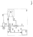
- Fig. 1 shows schematically the flow diagram of a dialysis machine, which contains the device according to the invention.
- a connecting line 12 leads to dialysate preparation unit 20.
- a plug connection is designated by 13, which connects a recirculation line (103, 120, 121, 122) to water inlet container 10 allowed.
- the dialysate preparation unit is supplied with hemodialysis concentrate via lines 21 and 22. This is usually a so-called acid concentrate or bicarbonate concentrate. Instead of two concentrates, a single concentrate or more than 2 concentrates can also be added. In the latter case, more lines are required. Dialysate is mixed, heated and degassed in the dialysate preparation unit. The dialysate enters the liquid balancing unit 30 via the line 23.
- the liquid balancing unit can be a system based on balancing chambers or a system based on flow meters.
- Such systems include in the work of the inventor: "Polaschegg HD. Methods and history of ultrafiltration control in hemodialysis. Scientific info. Fresenius Foundation Current Nephrology 1985; 18: 135-49".
- the flow measuring or control device for the fresh dialysate is the flow measuring or control device for the fresh dialysate. From there, the fresh dialysate reaches the dialyzer 40 via line 33 and an unspecified plug connection. Alternatively, line 33 can be connected to the short flow piece 41, which enables the cleaning and disinfection of the hemodialysis machine after dialysis has ended. From the dialyzer 40 or short-circuiting piece 41, the dialyzing liquid consumed in the case of dialysis reaches the outlet-side flow measuring or control device 32 and from there via line 35 to the sampling and recirculation unit 100 according to the invention. Monitoring and protective devices for monitoring the correct composition of the are not shown Dialysis liquid or the function of the liquid balancing device.
- the sampling and recirculation device 100 consists of a branch piece 101, which is fed via line 35 with used dialysis fluid. From there, the dialysis fluid either reaches the drain via line 102, shut-off valve 110 and line 111 or alternatively via line 103 to shut-off valve 120.
- a line 121 leads from valve 120 to plug connection 122.
- Plug connection 122 can be connected to plug connection 13, thereby creating a recirculation circuit can be produced for disinfection or sterilization.
- plug connection 122 can be connected to plug connection 123. In this state, a collection of dialysate samples in the sample collection container 124 connected to the plug connection 123 is possible.
- a container with a liquid or solid disinfectant concentrate can be inserted between plug connection 122 and 13, as described, for example, in the CleanCart TM brochure from Gambro, Lund, Sweden.
- the sample collection container is preferably a flexible bag made of a material with low gas permeability.
- the absorption capacity is typically 2 l, what corresponds to approximately 2% of the dialysis fluid consumed in the course of a dialysis treatment.
- Valves 110 and 120 are controlled by the control device 150. If sampling is not desired, valve 120 remains closed and valve 110 remains open. For sampling, the valve 110 is now closed at the same time intervals while the valve 120 is opened.
- the respective opening time of the two valves is dimensioned such that the ratio corresponds to the desired ratio of sample amount to total amount of dialysis fluid.
- the preferred amount of sample is 1-2%.
- the frequency of sampling should be at least three times per dialysis and the upper limit is only the switching speed of the valves.
- the switching frequency is preferably between 30 and 100 per dialysis. For a dialysis period of 3 h (180 min), there are intervals of 6 minutes for a switching frequency of 30 / dialysis, the sampling valve 120 being opened for 7.2 seconds (2% of the time).
- valve 110 remains open and valve 120 closed for a period of typically 5 minutes after the start of the disinfection process in order to flush the dialysis machine of dialysis fluid. Then valve 110 is closed and valve 120 is opened. At the same time, the water and concentrate supply to the dialysis machine is also interrupted in a manner not shown. The water in the dialysis machine, possibly mixed with a disinfectant and / or heated, is now recirculated in a known manner through the hemodialysis machine, whereby it is disinfected or sterilized.
- the further embodiment of the invention relates to the control of the valves 110 (outlet valve) and 120 (sampling valve).
- the sampling interval is the period from the opening of the outlet interval to the subsequent opening of the outlet valve.
- the sampling interval thus begins with the opening of the exhaust valve, includes the closing of the exhaust valve and ends with the re-opening of the exhaust valve.
- the sampling valve is closed at the beginning, then opened and closed again at the end of the sampling interval.
- the control of the sampling valve or outlet valve can be purely time-dependent, such as already described. In order to compensate for fluctuations in the dialysate flow or the pressure conditions at larger sampling time intervals, the control can also take place as a function of volume.
- a flow meter is inserted in the dialysate line in front of branching point 101 and the opening duration of the sampling valve (120) is controlled for each time interval in such a way that the sample amount corresponds to the predetermined proportion of the total amount in the sampling interval.
- the sampling valve is opened for a shorter time in order to keep the volume ratio constant.
- the opening time can also be controlled by the volume sensor.
- the valves 110 and 120 are controlled so that the volume ratio corresponds to the predetermined one, the time interval being predetermined.
- the control causes the sampling to take place in a fixed time interval, but the sampling volume is adapted to the dialysate volume processed in the opening time interval of the outlet valve. If the hemodialysis machine is carried out via a volumetric liquid balancing unit, the volume measuring device for used dialysate (32) can be used as a measuring device for controlling valves 110 and 120.
- control of the valves 110 and 120 can also take place in such a way that the sampling valve is opened when a predetermined amount of dialysate is reached.
- n is the division ratio, which, with a filling volume of the balance chamber of 30 ml, is typically 30 - 100.
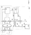
- FIG. 2 shows a detail from FIG. 1.
- a line 153 is added, which leads from a flow measuring device (155) for the used dialysate to the control device 150. If the hemodialysis machine has a liquid balancing device with flow meters, this device can also be used. In this case, the flow measuring device 155 is identical to the measuring device for used dialysate 32.
- FIG. 3 shows a detail from FIG. 1 with a liquid balancing device 30 which works with the aid of a balancing chamber.
- the liquid balancing device 30 consists of a balancing chamber 36 and the four valves 37 a-d, which are controlled by the control device 38. This controls the valves 37 in such a way that the valves 37a and d are opened and the valves 37b and c are closed during a filling phase. From this state, the balance chamber is switched to the circulation phase, the valves 37b and c being opened and the valves 37a and d being closed.
- a signal line 154 leads from the balancing chamber control device 38 to the sampling control device 150.
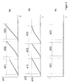
- FIGS. 4 a to c schematically show the mode of operation of the sampling control device 150 for the above-described embodiments of the invention, which are shown in FIGS. 2 and 3.
- FIG. 4a shows the control of the sampling valve 120 with the aid of the arrangement shown in FIG. 2, in which a flow meter is used to measure the dialysate used.
- the time axis is labeled t in the diagram.
- dV represents the volume flowing through the outlet valve 110 in the time interval.
- the outlet valve 110 remains open for a predetermined time interval.
- the opening time intervals 401, 402, 403 for the exhaust valve (110) are thus the same size. In the figure, they are delimited by dashed lines. At the intervals therebetween, the outlet valve 110 is closed and the sampling valve 120 is opened.
- the closing time of the valve 110 or opening time of the Adjusted valve 120 accordingly.
- the flow is constant in the interval 401, which leads to a linear increase in the processed volume dV.
- interval 402 the volume increases nonlinearly, the flow increases towards the end. Since the flow at the end of the interval is greater than the mean flow in the interval, the subsequent opening time of the sampling valve 120 is controlled so that the volume ratio of sample amount / total amount of dialysate used corresponds to the predetermined one. In the present case, this leads to a reduction in the opening time.
- FIG. 4b shows a further alternative for regulating the opening time of the sampling interval.
- the outlet valve is closed and the sampling valve is opened when a predetermined amount of used dialysis fluid (eg 1 l) is reached. This amount is designated 410 in the figure.
- FIG. 4b schematically shows a constant flow for the interval 411, a constant flow for the interval but also a larger flow compared to 411 and a decreasing flow for the interval 413. Accordingly, the time intervals 411,412,413 have different lengths.
- the opening time of the sampling valve can either be calculated according to formula (1) or regulated by the flow meter as already described.
- Figure 4c shows an alternative to controlling the opening times of the valves, if one Volume measuring device with balance chambers is used.
- the sampling intervals depend on the foot. In FIG. 4c it is assumed by way of example that the flow increases in the interval 422. The distances between the balance chamber impulses are smaller and the interval 422 overall is shorter than the neighboring intervals.
- the partial dialysate collection method allows the amount of substance removed to be calculated, but does not provide any information about the kinetics of this process, i.e. whether the drop in concentration over time e.g. corresponds to a 1-pool or 2-pool model.
- additional sampling valves that are connected in parallel to the one described, it is possible to obtain individual samples at the beginning and end of the dialysis treatment. From this or in combination with the dialysate sample collected over the entire duration of the dialysis, statements can then be made about the kinetics of the process.
- a switchable sampling device can also be connected. This can either contain several valves or a container change device.
- Both a rigid container and a bag can be used as the sample collection container.
- a sterile or sterilizable container is preferred.
- a bag is particularly preferred which is closed by a septum and consists of a material with low gas permeability. The low gas permeability prevents CO2 from escaping from the dialysate, which would lead to a change in the pH.
- a septum as a receptacle-side connector (123) is particularly inexpensive.
- the device-side plug connection 122 then preferably consists of a mandrel, as is known from infusion lines, which protrudes from a lockable plug connection.
- the clutch (13) on The water inlet then consists of a counterpart to this lockable plug-in connection.
- a lockable plug-in connection is, for example, a Luer-Lock connection, as is common in medical technology.
- the coupling 13 may also include a check valve or an automatic locking mechanism that closes the opening when the connector 122 is not connected to the coupling 13.
- a sensor can also be attached to the coupling 13, which allows the connection of the plug 122 to the coupling 13 to be detected. If a connection of plug 122 and coupling 13 is detected by this sensor during a hemodialysis treatment, the sampling valve is closed independently of a running sampling program and the outlet valve is opened, the sampling program is therefore interrupted or the start of a sampling program is prevented. This avoids the recirculation of used dialysate during hemodialysis treatment.
- the sampling valve 120 remains open and the outlet valve 110 is closed.
- the disinfection program can only be started if the connection between connector 122 and coupling 13 has been detected by the above-mentioned sensor. In the event that the solution of this connection is detected by the sensor during the disinfection, the disinfection program is terminated and the sampling valve 120 is closed.
- a mechanical microswitch, a magnetic or an optical sensor, for example, can be used as the sensor.
Abstract
Description
Die Erfindung betrifft eine Einrichtung und ein Verfahren zur Ermittlung der Effektivität einer Hämodialysebehandlung bzw. der bei einer Hämodialysebehandlung entfernten Urämietoxine.The invention relates to a device and a method for determining the effectiveness of a hemodialysis treatment or of the uremia toxins removed during a hemodialysis treatment.
Die chronische Hämodialysebehandlung ist die am meisten verbreitete Nierenersatztherapie. Ungefähr 500000 Patienten leben mit dieser Therapie, da bessere Alternativen wie z.B. die Transplantation von Kadavernieren für sie nicht zur Verfügung stehen.
Die Behandlungskosten, die insgesamt etwa 50000 US$ pro Jahr und Patient ausmachen haben zu einer enormen Belastung der Krankenversicherungen und des Gesundheitssystems geführt. Nur ein Teil der Kosten ist durch die Hämodialysebehandlung direkt hervorgerufen, der größere Teil fällt auf sonstige Behandlungen Krankenhausaufenthalte, Blutanschlußprobleme und Transport zur Dialysestation. Der Druck zur Kosteneinsparung trifft jedoch die eigentliche Dialysebehandlung, da diese schematisiert ist und von großen Organisation durchgeführt wird.Chronic hemodialysis treatment is the most common kidney replacement therapy. Approximately 500,000 patients live with this therapy because they have no better alternatives, such as the transplantation of carcasses.
The total cost of treatment, which amounts to approximately US $ 50,000 per patient per year, has put enormous strain on health insurance and the health system. Only a part of the costs is directly caused by the hemodialysis treatment, the greater part falls on other treatments, hospital stays, blood connection problems and transport to the dialysis station. However, the pressure to save costs affects the actual dialysis treatment, since this is schematic and is carried out by large organizations.
Der Druck auf die Behandlungskosten hat zu einer Verringerrung der Hämodialysezeit und häufig auch der Hämodialysequantität geführt. In den USA, wo etwa 92 % der Behandlungen über eine staatliche Organisation (Medicare) finanziert werden und eine umfangreiche statistische medizinische Datenbasis besteht, beobachtete man in den 80er Jahren einen Rückgang der Überlebenswahrscheinlichkeit von Patienten, der auf eine Verringerrung der Dialysedosis pro Behandlung zurückgeführt wurde. Auf Grund dieser Erkenntnis wurden Forschungsarbeiten intensiviert, mit dem Ziel, die minimal nötige und die optimale Dialysedosis zu ermitteln. Dadurch ausgelöst begann auch eine intensivere Forschung nach Methoden, die verabreichte Dialysedosis zuverlässig und kostengünstig zu ermitteln. Die Betonung ''kostengünstig'' ist deshalb wichtig, da der auslösende Grund ja gerade die Kosteneinsparung war. Eine Meßmethode, welche die Kosten wesentlich erhöht, kann den Zweck, eine ausreichende Dialysebehandlung bei gleichem Kostenaufwand zu garantieren, nicht erfüllen, da dann der Aufwand für die eigentliche Behandlung weiter verringert werden muß.Pressure on treatment costs has reduced hemodialysis time and often hemodialy sequencing. In the United States, where about 92% of treatments are funded through a government organization (Medicare) and there is an extensive statistical medical database, a decrease in the likelihood of patient survival was observed in the 1980s, which was attributed to a reduction in the dialysis dose per treatment . Based on this knowledge, research work was intensified with the aim of determining the minimum necessary and the optimal dialysis dose. As a result, more intensive research began on methods to determine the administered dialysis dose reliably and inexpensively. The emphasis '' inexpensive '' is important because the triggering reason was the cost savings. A measuring method that significantly increases the costs cannot serve the purpose of guaranteeing adequate dialysis treatment at the same cost, since then the effort for the actual treatment must be further reduced.
Aufgabe dieser Erfindung ist es, eine Einrichtung und ein Verfahren anzugeben, das mit minimalem Hardwareaufwand im Dialysegerät die Ermittlung der Menge an entfernten Urämietoxinen ermöglicht, ohne Blutproben zu erfordern.
Eine weitere Aufgabe dieser Erfindung ist es, ein Verfahren anzugeben, ein Dialysegerät so zu sterilisieren, daß das Ergebnis der Erfassung der Menge an Urämietoxinen nicht durch bakterielle Kontamination beeinträchtigt wird.The object of this invention is to provide a device and a method that with Minimal hardware expenditure in the dialysis machine enables the amount of uremia toxins removed to be determined without requiring blood samples.
Another object of this invention is to provide a method of sterilizing a dialysis machine so that the result of detecting the amount of uremia toxins is not affected by bacterial contamination.
Ein anerkanntes Verfahren zur Beurteilung der Dialyseeffektivität ist die Harnstoffkinetik. Die Reduktion der Plasmakonzentration von Harnstoff von Beginn zum Ende der Hämodialyse wird dabei als Maß für die Effektivität herangezogen. Es ist allgemein bekannt, daß Harnstoff nicht akut toxisch ist und in diesem Fall lediglich als Referenzsubstanz zur Messung herangezogen wird.
Die Harnstoffkinetikmethode ist z.B. in der Arbeit von: "Sargent JA, Gotch FA. Principles and Biophysics of Dialysis. Maher JF, editors. Replacement of Renal Function by Dialysis, 3rd ed.. Kluwer Academic Publishers,1989:87-143" ausführlich beschrieben. Die Standardmethode geht von einer gleichmäßigen Verteilung von Harnstoff im Ganzkörperwasser aus und wird deshalb 1-pool Modell genannt. Eine vollständige Messung umfaßt mindestens drei Blutproben. Je eine zu Beginn und Ende einer Behandlung und eine weitere vor Beginn der nächsten. Die Harnstoffkonzentration fällt während der Dialyse exponentiell ab. Aus den genannten beiden ersten Harnstoffmessungen zu Beginn und Ende der Dialyse kann nun der Exponentialkoeffizient diese Abfalls errechnet werden, der durch ![]()
Aus der 2. und 3. Messung der beschriebenen Meßserie läßt sich die Menge des durch den Metabolismus erzeugten Harnstoffs bestimmen, aus dem wiederum, wie in "Replacement of Renal Function by Dialysis" beschrieben, die Menge an umgesetzten Protein (Protein Catabolic Rate) berechnet werden kann. Diese ist von Bedeutung, da man festgestellt hat, daß die Überlebenswahrscheinlichkeit sehr stark vom Plasmaalbumingehalt und dieser wiederum von der Proteinaufnahme abhängt.A recognized method for assessing the effectiveness of dialysis is urea kinetics. The reduction in the plasma concentration of urea from the beginning to the end of hemodialysis is used as a measure of the effectiveness. It is generally known that urea is not acutely toxic and in this case is only used as a reference substance for the measurement.
The urea kinetic method is described in detail, for example, in the work of: "Sargent JA, Gotch FA. Principles and Biophysics of Dialysis. Maher JF, editors. Replacement of Renal Function by Dialysis, 3rd ed .. Kluwer Academic Publishers, 1989: 87-143" . The standard method assumes an even distribution of urea in the whole body water and is therefore called a 1-pool model. A complete measurement includes at least three blood samples. One each at the beginning and end of one treatment and another one before the start of the next. The urea concentration drops exponentially during dialysis. From the two first urea measurements mentioned at the beginning and end of the dialysis, the exponential coefficient of this waste can be calculated by ![]()
The amount of urea produced by the metabolism can be determined from the second and third measurement of the series of measurements described, from which, as described in "Replacement of Renal Function by Dialysis", the amount of protein converted (protein catabolic rate) is calculated can be. This is important because it has been found that the probability of survival depends very much on the plasma albumin content and this in turn depends on the protein intake.
Die Verkürzung der Dialysezeit bei gleichzeitiger Erhöhung der Clearance hat dazu geführt, daß das oben beschriebene 1-pool Modell den tatsächlichen Vorgang nur mehr ungenügend beschreibt. Der Fehler kann dabei bis zu 40% betragen. Man ist daher zu 2-pool Modellen übergegangen, zu deren Charakterisierung wenigstens 3 intradialytische Blutproben erforderlich sind, wobei die letzte etwa 30 bis 60 Minuten nach Beendigung der Hämodialyse genommen wird Dies hat die Charakterisierung der Behandlungsquantität weiter erschwert.The shortening of the dialysis time with a simultaneous increase in clearance has resulted in the 1-pool model described above only insufficiently describing the actual process. The error can be up to 40%. One has therefore switched to 2-pool models, the characterization of which requires at least 3 intradialytic blood samples, the last one being taken about 30 to 60 minutes after the end of hemodialysis. This has further complicated the characterization of the treatment quantity.
Seit Beginn der Hämodialysebehandlungstechnik hat man versucht, die entfernten Urämietoxine im der Austauschflüssigkeit zu messen. Dazu wurde die gesamte Dialysierflüssigkeit aufgefangen und die Menge bestimmt (siehe z.B. Lankhorst BJ, Ekllis P, Nosse C, Malchesky P, Magnusson MO. A Practical Guide to Kinetic Modeling Using the Technique of Direct Dialysis Quantification. Dialysis & Transplantation 1983;12:694-706). Die Konzentration von Harnstoff und anderen Urämietoxinen in einer Probe dieser Dialysierflüssigkeit wurde bestimmt und mit der Menge multipliziert. Daraus ergab sich die Gesamtmenge an entfernter Substanz. Dieses Verfahren ist jedoch für die Routine zu unpraktisch, da über 100 l Dialysierflüssigkeit gesammelt, gewogen und gemischt werden müssen. Schließlich hat sich herausgestellt, daß Harnstoff von Bakterien schnell metabolisiert wird, verbrauchte Dialysierflüssigkeit gewöhnlich stark bakteriell kontaminiert ist und somit die gemessene Harnstoffkonzentration nicht den wahren Wert wiedergibt.Since the beginning of the hemodialysis treatment technique, attempts have been made to measure the uremia toxins removed in the exchange fluid. For this purpose, the entire dialysis fluid was collected and the amount determined (see, for example, Lankhorst BJ, Ekllis P, Nosse C, Malchesky P, Magnusson MO.A Practical Guide to Kinetic Modeling Using the Technique of Direct Dialysis Quantification. Dialysis & Transplantation 1983; 12: 694 -706). The concentration of urea and other uremia toxins in a sample of this dialysis fluid was determined and multiplied by the amount. This resulted in the total amount of substance removed. However, this procedure is too impractical for the routine, since over 100 l of dialysis fluid must be collected, weighed and mixed. Finally, it has been found that urea is rapidly metabolized by bacteria, that used dialysis fluid is usually heavily contaminated with bacteria, and thus the measured urea concentration does not reflect the true value.
Um das Problem der großen Flüssigkeitsmenge zu beseitigen, hat man vorgeschlagen, lediglich einen Teil der verbrauchten Dialysierflüssigkeit aufzufangen. Dieses Verfahren wird Partielle Dialysatsammlung, englisch partial dialysate collection genannt. Dabei wird etwa 1% der verbrauchten Dialysierflüssigkeit kontinuierlich gesammelt. Am Ende wird die aufgefangene Menge gewogen, gemischt und eine Probe entnommen, die analysiert wird. Die in der Probe gefundene Konzentration wird mit der Menge multipliziert und durch den Anteilsfaktor (Verhältnis aus Gesamtdialysat/gesammelten Dialysat) multipliziert. Daraus ergibt sich die gesamte entfernte Menge. Mit diesem Verfahren beseitigt man das Mengenproblem, nicht jedoch das der bakteriellen Kontamination. Man kann nun die zur Sammlung bestimmte Teilmenge an verbrauchter Dialysierflüssigkeit durch ein Sterilfilter in den Probenaufnahmebehälter leiten. Dies löst das Problem der bakteriellen Kontamination, allerdings unter Inkaufnahme erhöhter Kosten.In order to eliminate the problem of the large amount of liquid, it has been proposed to collect only a part of the dialysis liquid used. This process is called partial dialysate collection. About 1% of the dialysis fluid used is continuously collected. At the end, the collected amount is weighed, mixed and a sample is taken for analysis. The concentration found in the sample is multiplied by the amount and multiplied by the proportion factor (ratio of total dialysate / collected dialysate). This gives the total amount removed. This method eliminates the quantity problem, but not the bacterial contamination. The portion of the dialysis fluid used for collection can now be passed through a sterile filter Guide the sample container. This solves the problem of bacterial contamination, but at an increased cost.
Mehrere Verfahren sind bekannt, um eine partielle Dialysatsammlung durchzuführen: Stiller und Schaefer (Stiller Siegfried, Schaefer Udo, inventors. Stiller Siegfried, assignee. Passiver Dialysatfluss-Teiler. DE patent 3312909. 10/18/84) beschreiben einen passiven Flußteiler bei dem der gesamte Dialysatfluß durch eine Vielzahl von Kapillaren geleitet wird. Über eine oder mehrere Kapillaren wird ein Teilstrom zur partiellen Dialysatsammlung entnommen. Nachteil dieser Anordnung ist, daß schon geringfügige Veränderungen der Strömung das Teilerverhältnis verändern können, ohne daß dies bemerkbar wird. Ähnliches trifft auf eine Anordnung zu, bei der eine Kanüle in den Dialysatfluß eingeführt wird (Ing TS, YU AW, Khalaf MN, Tiwari P, Rafiq M, Khan AA, Nawab ZM. Collection of Hemodialysate Aliquot Whose Composition Reflects That of Total Dialysate. ASAIO Abstracts 1994;:85).Several methods are known for carrying out a partial dialysate collection: Stiller and Schaefer (Stiller Siegfried, Schaefer Udo, inventors. Stiller Siegfried, assignee. Passive dialysate flow divider. DE patent 3312909. 10/18/84) describe a passive flow divider in which the entire dialysate flow is passed through a variety of capillaries. A partial stream for partial dialysate collection is withdrawn via one or more capillaries. The disadvantage of this arrangement is that even slight changes in the flow can change the divider ratio without this being noticeable. The same applies to an arrangement in which a cannula is inserted into the dialysate flow (Ing TS, YU AW, Khalaf MN, Tiwari P, Rafiq M, Khan AA, Nawab ZM. Collection of Hemodialysate Aliquot Whose Composition Reflects That of Total Dialysate. ASAIO Abstracts 1994;: 85).
Eine andere Anordnung (Aviram A, Peters JH, Gulyassy PF. Dialysance of Amino Acids and Related Substances. Nephron 1971;8:440-54) arbeitet mit einer Pumpe, die einen Teilstrom aus dem Dialysatstrom entnimmt. Diese Anordnung hat den Nachteil, daß der Dialysatfluß konstant gehalten werden oder aber die Rate der Teilstrompumpe entsprechend nachgeführt werden muß.Another arrangement (Aviram A, Peters JH, Gulyassy PF. Dialysance of Amino Acids and Related Substances. Nephron 1971; 8: 440-54) works with a pump that takes a partial flow from the dialysate flow. This arrangement has the disadvantage that the dialysate flow must be kept constant or the rate of the partial flow pump must be adjusted accordingly.
Beide Verfahren haben den Nachteil, die Probe aus einem Bereich des Hydrauliksystems zu entnehmen, der üblicherweise bakteriell kontaminiert ist und in Geräten, deren Sterilisation oder Desinfektion in Rezirkulation erfolgt, nie desinfiziert bzw. sterilisiert wird.Both methods have the disadvantage of taking the sample from an area of the hydraulic system which is usually bacterially contaminated and is never disinfected or sterilized in devices whose sterilization or disinfection takes place in recirculation.
Hämodialysegeräte müssen von Zeit zu Zeit, üblicherweise wenigstens einmal am Tag desinfiziert werden. Sie werden laufend neu kontaminiert: Durch unsteriles Wasser, unsteriles Dialysekonzentrat aber auch durch die Anschlußprozedur von Dialysatoren, die dialysierflüssigkeitsseitig üblicherweise nicht aseptisch erfolgt. In einigen Geräten erfolgt die Desinfektion durch Erhitzung des zuströmenden Wassers auf mehr als 85 Grad C oder durch Beimischung eines Desinfektionsmittels. Das Hitzeverfahren wird dabei zunehmend bevorzugt, da es ohne potentiell umweltgefährdende Desinfektionsmittel auskommt. Es hat jedoch den Nachteil, daß Keime im Wasser wegen der kurzen Durchlaufzeit nicht vollständig abgetötet werden. Sofern also die Wasserversorgung kontaminiert ist, wird das Gerät laufend neu kontaminiert.
Einige Geräte verfügen über Dialysatfilter, die unmittelbar vor dem Dialysator das Dialysat sterilfiltrieren. Diese müssen ihrerseits gespült werden, was üblicherweise während des Desinfektionsvorganges erfolgt. Dadurch geraten Keime am Dialysatoranschluß vorbei zur Abflußleitung, die somit rekontaminiert wird.
Es sind deshalb Geräte entwickelt worden, die eine laufende Rekontamination dadurch verhindern, daß nach einer initialen Spül- und Reinigungsphase das Gerät so geschaltet wird, daß Wasser bzw. Desinfektionslösung im Gerät rezirkuliert. Dadurch wird das Gerät sowohl vom Zufluß als auch vom Abfluß getrennt und kann nicht mehr rekontaminiert werden. Eine solche Anordnung ist z.B. in der DE 3447989 (Polaschegg HD, inventors. Fresenius AG, assignee. Hämodialysevorrichtung. DE patent 3447989.7/16/87) beschrieben. Die Zugabe des Desinfektionsmittels kann dabei über einen Desinfektionsmittelbehälter erfolgen, der in den Rezirkulationskreislauf eingefügt wird, wie z.B. in der DE 4138140 (Polaschegg HD, inventors. Fresenius AG, assignee. Vorrichtung zur Desinfektion von Hämodialysegeräten mit einem pulverförmigen Konzentrat. DE patent 4138140. 12/23/93) beschrieben.Hemodialysis machines need to be disinfected from time to time, usually at least once a day. They are continually contaminated: by non-sterile water, non-sterile dialysis concentrate, but also by the connection procedure of dialyzers, which is usually not aseptic on the dialysis fluid side. In some devices, disinfection is carried out by heating the inflowing water to more than 85 degrees C or by adding a disinfectant. The heat process is increasingly preferred because it does not use potentially disinfectants that are harmful to the environment. However, it has the disadvantage that germs in the water are not completely destroyed because of the short throughput time. If the water supply is contaminated, the device is continuously contaminated.
Some devices have dialysate filters that sterile filter the dialysate directly in front of the dialyzer. These in turn have to be rinsed, which usually takes place during the disinfection process. As a result, germs get past the dialyzer connection to the drain line, which is thus recontaminated.
Devices have therefore been developed which prevent ongoing recontamination by switching the device after an initial rinsing and cleaning phase in such a way that water or disinfectant solution recirculates in the device. As a result, the device is separated from both the inflow and the outflow and can no longer be recontaminated. Such an arrangement is described, for example, in DE 3447989 (Polaschegg HD, inventors. Fresenius AG, assignee. Hemodialysis device. DE patent 3447989.7 / 16/87). The disinfectant can be added via a disinfectant container that is inserted into the recirculation circuit, such as in DE 4138140 (Polaschegg HD, inventors. Fresenius AG, assignee. Device for disinfecting hemodialysis machines with a powdered concentrate. DE patent 4138140. 12 / 23/93).
Nachteilig ist dabei, daß die Abflußleitung, aus der üblicherweise der Teilstrom zur Probennahme entnommen wird, nicht desinfiziert wird.The disadvantage here is that the drain line, from which the partial flow is usually taken for sampling, is not disinfected.
Eine Einrichtung nach der vorliegenden Erfindung erlaubt, eine partielle Dialysatsammlung kontaminationsarm mit einem Hämodialysegerät durchzuführen, das mit einem Rezirkulationsverfahren desinfiziert bzw. sterilisiert wird.A device according to the present invention allows a partial dialysate collection to be carried out with low contamination with a hemodialysis device which is disinfected or sterilized using a recirculation method.
Dies erfolgt dadurch, daß der Rezirkulationszweig des Hämodialysegerätes zur Probennahme aufgetrennt wird und über eine Ventilschaltung ein Teilstrom der verbrauchten Dialysierflüssigkeit entnommen wird.This is done in that the recirculation branch of the hemodialysis machine is separated for sampling and a partial flow of the used dialysis fluid is removed via a valve circuit.
Eine weitere Aufgabe der Erfindung ist es, ein vereinfachtes Desinfektionsverfahren anzugeben, bei dem ein Behälter, der ein Desinfektionsmittelkonzentrat enthält, in den Rezirkulationskreislauf eingebracht wird.Another object of the invention is to provide a simplified disinfection method in which a container containing a disinfectant concentrate is introduced into the recirculation circuit.
Eine weitere Aufgabe der Erfindung ist die Angabe von Steuerungsverfahren zur Probenentnahme mit Hilfe zweier Ventile.Another object of the invention is to specify control methods for taking samples using two valves.
Fig 1 zeigt schematisch das Fließschema eines Dialysegerätes, das die erfindungsgemäße Einrichtung enthält.Fig. 1 shows schematically the flow diagram of a dialysis machine, which contains the device according to the invention.
Für die Hämodialyse geeignetes Wasser von einer nicht näher dargestellten Wasserquelle gelangt über die Leitung 11 in den Eingangsbehälter 10. Von dort führt eine Verbindungsleitung 12 zur Dialysataufbereitungseinheit 20. Mit 13 ist eine Steckverbindung bezeichnet, die die Verbindung einer Rezirkulationsleitung (103,120,121,122) mit dem Wassereingangsbehälter 10 erlaubt.Water suitable for hemodialysis from a water source (not shown in detail) reaches
Der Dialysataufbereitungseinheit wird Hämodialysekonzentrat über die Leitungen 21 und 22 zugeführt. Üblicherweise handelt es sich dabei um sogenanntes Säurekonzentrat bzw. Bicarbonatkonzentrat. Statt zweier Konzentrate kann aber auch ein einziges Konzentrat oder auch mehr als 2 Konzentrate zugeführt werden. Im letzteren Fall sind mehr Leitungen erforderlich. In der Dialysataufbereitungseinheit wird Dialysat gemischt, erwärmt und entgast. Über die Leitung 23 gelangt das Dialysat in die Flüssigkeitsbilanziereinheit 30.The dialysate preparation unit is supplied with hemodialysis concentrate via
Bei der Flüssigkeitsbilanziereinheit kann es sich um ein System basierend auf Bilanzkammern oder um ein System basierend auf Flußmessern handeln. Solche Systeme sind u.a. in der Arbeit des Erfinders: "Polaschegg HD. Methoden und Geschichte der Ultrafiltrationskontrolle in der Hämodialyse. Wiss. Info. Fresenius Stiftung Aktuelle Nephrologie 1985;18:135-49" beschrieben.The liquid balancing unit can be a system based on balancing chambers or a system based on flow meters. Such systems include in the work of the inventor: "Polaschegg HD. Methods and history of ultrafiltration control in hemodialysis. Scientific info. Fresenius Foundation Current Nephrology 1985; 18: 135-49".
31 ist die Flußmeß- oder Kontrollvorrichtung für das frische Dialysat. Von dort gelangt das frische Dialysat über Leitung 33 und eine nicht näher bezeichnete Steckverbindung zum Dialysator 40. Alternativ kann Leitung 33 mit dem Kurzscflußstück 41 verbunden werden, was die Reinigung und Desinfektion des Hämodialysegerätes nach Beendigung der Dialyse ermöglicht. Vom Dialysator 40 bzw. Kurzschlußstück 41 gelangt die, im Falle der Dialyse verbrauchte Dialysierflüssigkeit zur ausgangseitigen Flußmeß- oder Kontrollvorrichtung 32 und von dort über Leitung 35 zur erfindungsgemäßen Probennahme- und Rezirkulationseinheit 100. Nicht dargestellt sind Überwachungs- und Schutzvorrichtungen zur Überwachung der richtigen Zusammensetzung der Dialysierflüssigkeit bzw. der Funktion der Flüssigkeitsbilanziervorrichtung.31 is the flow measuring or control device for the fresh dialysate. From there, the fresh dialysate reaches the
Die Probennahme- und Rezirkulationseinrichtung 100 besteht aus einem Abzweigstück 101, das über die Leitung 35 mit verbrauchter Dialysierflüssigkeit gespeist wird. Von dort gelangt die Dialysierflüssigkeit entweder über Leitung 102, Absperrventil 110 und Leitung 111 zum Abfluß oder alternativ über Leitung 103 zu Absperrventil 120. Vom Ventil 120 führt eine Leitung 121 zur Steckverbindung 122. Die Steckverbindung 122 ist mit der Steckverbindung 13 verbindbar, wodurch ein Rezirkulationskreislauf zur Desinfektion bzw. Sterilisation herstellbar ist. Alternativ kann Steckverbindung 122 mit Steckverbindung 123 verbunden werden. In diesem Zustand ist eine Sammlung von Dialysatproben im, mit der Steckverbindung 123 verbundenen Probensammelbehälter 124 möglich. Zwischen Steckverbindung 122 und 13 ist ein Behälter mit einem flüssigen oder festen Desinfektionsmittelkonzentrat einfügbar, wie er z.B. im Prospekt CleanCart™ der Firma Gambro, Lund, Schweden beschrieben ist.
Bei dem Probensammelbehälter handelt es sich bevorzugt um einen flexiblen Beutel aus einem Material mit geringer Gasdurchlässigkeit. Das Aufnahmevermögen liegt typisch bei 2 l, was etwa 2% der im Laufe einer Dialysebehandlung verbrauchten Dialysierflüssigkeit entspricht. Ventil 110 und 120 werden von der Steuereinrichtung 150 gesteuert. Sollte keine Probennahme gewünscht werden, so bleibt Ventil 120 geschlossen und Ventil 110 geöffnet. Zur Probennahme wird nun in zeitlich gleichen Abständen das Ventil 110 geschlossen während das Ventil 120 geöffnet wird. Die jeweilige Öffnungszeit der beiden Ventile ist so bemessen, daß das Verhältnis dem gewünschten Verhältnis von Probenmenge zu Gesamtmenge an Dialysierflüssigkeit entspricht. Die bevorzugte Probenmenge beträgt 1 - 2%. Die Häufigkeit der Probennahme sollte mindestens drei mal pro Dialyse betragen und ist nach oben hin nur durch die Schaltgeschwindigkeit der Ventile begrenzt. Bevorzugt liegt die Schalthäufigkeit zwischen 30 und 100 pro Dialyse. Für eine Dialysedauer von 3 h (180 min) ergeben sich somit für eine Schalthäufigkeit von 30/Dialyse Intervalle von 6 Minuten, wobei das Probennahmeventil 120 jeweils für 7,2 Sekunden (2% der Zeit) geöffnet wird.The sampling and
The sample collection container is preferably a flexible bag made of a material with low gas permeability. The absorption capacity is typically 2 l, what corresponds to approximately 2% of the dialysis fluid consumed in the course of a dialysis treatment.
Zur Desinfektion bzw. Sterilisation wird, wie bereits beschrieben, der Stecker 122 mit der Steckverbindung 13 verbunden. Für eine Periode von typisch 5 Minuten nach Beginn des Desinfektionsvorganges bleibt Ventil 110 geöffnet und Ventil 120 geschlossen um das Dialysegerät von Dialysierfüssigkeit freizuspülen. Danach wird Ventil 110 geschlossen und Ventil 120 geöffnet. Gleichzeitig wird in nicht näher dargestellter Weise auch die Wasser- und Konzentratzuführ zum Dialysegerät unterbrochen. Das im Dialysegerät befindliche Wasser, eventuell mit einem Desinfektionsmittel versetzt und/oder erhitzt, rezirkuliert nun in bekannter Weise durch das Hämodialysegerät, wodurch dieses desinfiziert oder sterilisiert wird.As already described, the
Die weitere Ausgestaltung der Erfindung betrifft die Steuerung der Ventile 110 (Auslaßventil) und 120 (Probennahmeventil).
Im folgenden wird als Probennahmeintervall der Zeitraum vom Öffnen des Auslaßintervalls bis zum darauffolgenden Öffnen des Auslaßventils bezeichnet. Das Probennahmeintervall beginnt somit mit dem Öffnen des Auslaßventils, enthält das Schließen des Auslaßventils und endet mit dem Wiederöffnen des Auslaßventils. Das Probennahmeventil ist zu Beginn geschlossen, wird dann geöffnet und zu Ende des Probennahmeintervalls wieder geschlossen.
Die Steuerung des Probennahmeventils bzw. Auslaßventils kann rein zeitabhängig erfolgen, wie bereits beschrieben. Um bei größeren Zeitintervallen der Probennahme Schwankungen des Dialysatflußes oder der Druckverhältnisse auszugleichen, kann die Steuerung auch volumenabhängig erfolgen. Dazu wird in die Dialysatleitung vor dem Verzweigungspunkt 101 ein Flußmesser eingefügt und für jedes Zeitintervall die Öffnungsdauer des Probennahmeventils (120) so gesteuert, daß die Probenmenge dem vorgegebenen Anteil an der Gesamtmenge im Probennahmeintervall entspricht. Nimmt im Probennahmeintervall der Fluß zu, was bedeutet, daß das verarbeitete Dialysatvolumen zunimmt, so wird das Probennahmeventil für eine kürzere Zeit geöffnet, um das Volumenverhältnis gleich zu halten. Die Öffnungszeit kann gleichfalls durch den Volumensensor kontrolliert werden. In diesem Fall werden also die Ventile 110 und 120 so gesteuert, daß das Volumenverhältnis dem vorgegebenen entspricht, wobei das Zeitintervall vorgegeben ist. Die Steuerung bewirkt, daß die Probennahme zwar im festen Zeitintervall erfolgt, das Probennahmevolumen aber dem im Öffnungszeitintervall des Auslaßventiles verarbeiteten Dialysatvolumen angepaßt wird.
Sollte das Hämodialysegerät über eine volumetrische Flüssigkeitsbilanziereinheit erfolgen, so kann die Volumenmeßvorrichtung für verbrauchtes Dialysat (32) als Meßvorrichtung zur Steuerung der Ventile 110 und 120 herangezogen werden. The further embodiment of the invention relates to the control of the valves 110 (outlet valve) and 120 (sampling valve).
In the following, the sampling interval is the period from the opening of the outlet interval to the subsequent opening of the outlet valve. The sampling interval thus begins with the opening of the exhaust valve, includes the closing of the exhaust valve and ends with the re-opening of the exhaust valve. The sampling valve is closed at the beginning, then opened and closed again at the end of the sampling interval.
The control of the sampling valve or outlet valve can be purely time-dependent, such as already described. In order to compensate for fluctuations in the dialysate flow or the pressure conditions at larger sampling time intervals, the control can also take place as a function of volume. For this purpose, a flow meter is inserted in the dialysate line in front of branching
If the hemodialysis machine is carried out via a volumetric liquid balancing unit, the volume measuring device for used dialysate (32) can be used as a measuring device for controlling
Alternativ kann die Steuerung der Ventile 110 und 120 aber auch so erfolgen, daß das Probennahmeventil jeweils dann geöffnet wird, wenn eine vorherbestimmte Dialysatmenge erreicht wird.Alternatively, the control of the
Verfügt das Hämodialysegerät über eine volumetrische UF-Kontrolle mit Bilanzkammern, wie sie z.B. im Deutschen Patent: "Schäl W, inventors. Fresenius AG, assignee. Vorrichtung zur Hämodialyse und zum Entziehen von Ultrafiltrat. DE patent 2838414. 10/31/84" beschrieben ist, so kann die Bilanzkammerschaltung zur Steuerung der Probennahme herangezogen werden. Dazu wird das Probennahmeventil synchron mit jeder n-ten Bilanzkammerumschaltung geschaltet. n ist dabei das Teilerverhältnis, das, bei einem Füllvolumen der Bilanzkammer von 30 ml bei typisch 30 - 100 liegt.Does the hemodialysis machine have a volumetric UF control with balance chambers, as described, for example, in the German patent: "Schäl W, inventors. Fresenius AG, assignee. Device for hemodialysis and for removing ultrafiltrate. DE patent 2838414. 10/31/84" the balance chamber circuit can be used to control the sampling. For this purpose, the sampling valve is switched synchronously with every nth balancing chamber switchover. n is the division ratio, which, with a filling volume of the balance chamber of 30 ml, is typically 30 - 100.
Die beschriebenen Ausgestaltungen der Erfindung sind in den Figuren 2 und 3 sowie 4a-c näher dargestellt. Es zeigt Figur 2 einen Ausschnitt aus Figur 1. Hinzugefügt ist eine Leitung 153, die von einer Flußmeßvorrichtung (155) für das verbrauchte Dialysat zur Steuervorrichtung 150 führt. Sollte das Hämodialysegerät über eine Flüssigkeitsbilanziervorrichtung mit Flußmessern verfügen, so kann diese Einrichtung ebenfalls verwendet werden. In diesem Fall ist die Flußmeßvorrichtung 155 identisch mit der Meßvorrichtung für verbrauchtes Dialysat 32.The described embodiments of the invention are shown in more detail in FIGS. 2 and 3 and 4a-c. FIG. 2 shows a detail from FIG. 1. A
Figur 3 zeigt einen Ausschnitt aus Figur 1 mit einer Flüssigkeitsbilanziervorrichtung 30, die mit Hilfe einer Bilanzkammer arbeitet. Statt einer einzigen können auch zwei oder mehrere Bilanzkammern verwendet werden. Die Flüssigkeitsbilanziervorrichtung 30 besteht in diesem Fall aus einer Bilanzkammer 36 und den vier Ventilen 37 a-d, die von der Steuereinrichtung 38 gesteuert werden. Diese steuert die Ventile 37 so, daß während einer Füllphase jeweils die Ventile 37a und d geöffnet und die Ventile 37b und c geschlossen sind. Aus diesem Zustand wird die Bilanzkammer in die Zirkulationsphase geschaltet, wobei die Ventile 37b und c geöffnet und die Ventile 37a und d geschlossen werden. Von der Bilanzkammersteuereinrichtung 38 führt eine Signalleitung 154 zur Probennahmesteuereinrichtung 150.FIG. 3 shows a detail from FIG. 1 with a
Figur 4 a bis c zeigt schematisch die Wirkungsweise der Probennahmesteuereinrichtung 150 für die weiter oben beschriebenen Ausgestaltungen der Erfindung die in Figur 2 und 3 dargestellt sind.
Figur 4a zeigt die Steuerung des Probennahmeventils 120 mit Hilfe der in Figur 2 dargestellten Anordnung, bei der ein Flußmesser zur Messung des verbrauchten Dialysats verwendet wird. Im Diagramm ist die Zeitachse mit t bezeichnet. dV stellt das im Zeitintervall durch das Auslaßventil 110 strömende Volumen dar. Das Auslaßventil 110 bleibt dabei jeweils für ein vorgegebenes Zeitintervall geöffnet. Die Öffnungszeitintervalle 401, 402, 403 für das Auslaßventil (110) sind somit gleich groß. In der Figur werden sie durch strichlierte Linien begrenzt. In den dazwischenliegenden Intervallen wird das Auslaßventil 110 geschlossen und das Probennahmeventil 120 geöffnet. Sollte sich innerhalb eines Öffnungszeitintervalls des Auslaßventils der Fluß ändern, so wird die Schließzeit des Ventils 110 bzw. Öffnungszeit des Ventils 120 entsprechend angepaßt. In der Figur 4a ist im Intervall 401 der Fluß konstant, was zu einer linearen Zunahme des verarbeiteten Volumens dV führt. Im Intervall 402 nimmt das Volumen nichtlinear zu, der Fluß steigt gegen Ende an. Da der Fluß am Ende des Intervalls größer als der mittlere Fluß im Intervall ist, wird die darauffolgende Öffnungszeit des Probennahmeventils 120 so gesteuert, daß das Volumenverhältnis Probenmenge/Gesamtmenge verbrauchtes Dialysat dem vorgegebenen entspricht. Im vorliegenden Fall führt dies zu einer Verkürzung der Öffnungszeit.
Die Berechnung des Öffnungsintervalls erfolgt dabei nach folgendem Schema: Es sei V das im Öffnungszeitintervalls des Auslaßventils geförderte Volumen, q(T) der zeitabhängige Fluß des verbrauchten Dialysats am Ende des Intervalls T wobei der zeitliche Beginn des Intervalls jeweils zu 0 gesetzt wird. tp ist die Öffnungszeit des Probennahmeventils und F das vorgegebene Verhältnis von Probenmenge zur Gesamtmenge an Dialysierflüssigkeit, z.B. 0,03.![]()
Figur 4b zeigt eine weitere Alternative der Regelung der Öffnungszeit des Probennahmeintervalls. Das Auslaßventil wird jeweils geschlossen und das Probennahmeventil geöffnet, wenn eine vorherbestimmte Menge an verbrauchter Dialysierflüssigkeit (z.B. 1 l) erreicht wird. Diese Menge ist in der Figur mit 410 bezeichnet. Schematisch zeigt die Figur 4b für das Intervall 411 einen konstanten Fluß, für das Intervall gleichfalls einen konstanten, jedoch gegenüber 411 größeren Fluß und für das Intervall 413 einen abnehmenden Fluß. Dementsprechend sind die Zeitintervalle 411,412,413 unterschiedlich lang. Die Öffnungszeit des Probennahmeventils kann entweder nach Formel (1) berechnet oder aber durch den Flußmesser wie schon beschrieben geregelt werden.
Figur 4c zeigt eine Alternative zur Steuerung der Öffnungszeiten der Ventile, falls eine Volumenmeßvorrichtung mit Bilanzkammern verwendet wird. Über der Zeitachse sind dabei die Bilanzkammerumschaltimpulse als kurze Striche aufgetragen. Nach einer vorgegebenen Anzahl von Impulsen (im Beispiel sind es 20) wird das Auslaßventil für eine ebenfalls vorgegebene Anzahl an Impulsen (im Beispiel 3) geschlossen bzw. das Probennahmeventil geöffnet. Da ein Bilanzkammertakt jeweils einem bestimmten Volumen entspricht ergibt sich somit ein Verhältnis für das Probenvolumen und Gesamtvolumen, das unabhängig vom Fluß ist und dem Verhältnis F entspricht. Im Beispiel ist F = 3/23. Die Probennahmeintervalle sind dabei vom FIuß abhängig. In Figur 4c ist beispielhaft angenommen, daß der Fluß im Intervall 422 zunimmt. Die Abstände der Bilanzkammerimpulse sind geringer und das Intervall 422 insgesamt kürzer als die Nachbarintervalle.FIGS. 4 a to c schematically show the mode of operation of the
FIG. 4a shows the control of the
The opening interval is calculated according to the following scheme: Let V be the volume delivered in the opening time interval of the exhaust valve, q (T) the time-dependent flow of the used dialysate at the end of the interval T, the time start of the interval being set to 0. tp is the opening time of the sampling valve and F is the predetermined ratio of the sample amount to the total amount of dialysis fluid, eg 0.03. ![]()
FIG. 4b shows a further alternative for regulating the opening time of the sampling interval. The outlet valve is closed and the sampling valve is opened when a predetermined amount of used dialysis fluid (eg 1 l) is reached. This amount is designated 410 in the figure. FIG. 4b schematically shows a constant flow for the
Figure 4c shows an alternative to controlling the opening times of the valves, if one Volume measuring device with balance chambers is used. The balance chamber changeover impulses are plotted as short lines over the time axis. After a predetermined number of pulses (in the example there are 20), the outlet valve is closed for a likewise predetermined number of pulses (in Example 3) or the sampling valve is opened. Since a balancing chamber cycle corresponds to a certain volume, this results in a ratio for the sample volume and total volume, which is independent of the flow and corresponds to the ratio F. In the example, F = 3/23. The sampling intervals depend on the foot. In FIG. 4c it is assumed by way of example that the flow increases in the
Die Methode der partiellen Dialysatsammlung erlaubt die Berechnung der Menge an entfernter Substanz, sie gibt aber keine Auskunft über die Kinetik diese Vorganges, d.h. ob der Abfall der Konzentration über die Zeit z.B. einem 1-pool oder 2-pool Modell entspricht. Durch die Verwendung von zusätzlichen Probennahmeventilen, die parallel zum beschriebenen geschaltet werden, ist es möglich, einzelne Proben zu Beginn und zum Ende der Dialysebehandlung zu gewinnen. Daraus oder in Kombination mit dem über die gesamte Dialysedauer gesammelten Dialysatprobe lassen sich dann Aussagen über die Kinetik des Vorganges machen. An Stelle von mehreren Ventilen kann auch eine umschaltbare Probennahmevorrichtung nachgeschaltet werden. Diese kann entweder ihrerseits mehrere Ventile enthalten oder aber eine Auffangbehälterwechselvorrichtung.The partial dialysate collection method allows the amount of substance removed to be calculated, but does not provide any information about the kinetics of this process, i.e. whether the drop in concentration over time e.g. corresponds to a 1-pool or 2-pool model. By using additional sampling valves that are connected in parallel to the one described, it is possible to obtain individual samples at the beginning and end of the dialysis treatment. From this or in combination with the dialysate sample collected over the entire duration of the dialysis, statements can then be made about the kinetics of the process. Instead of several valves, a switchable sampling device can also be connected. This can either contain several valves or a container change device.
Als Probenauffangbehälter kann sowohl ein starres Gefäß als auch ein Beutel verwendet werden. Ein steriler oder sterilisierbarer Behälter ist bevorzugt. Besonders bevorzugt ist ein Beutel, der durch ein Septum verschlossen ist und aus einem Material mit geringer Gasdurchlässigkeit besteht. Die geringe Gasdurchlässigkeit verhindert, daß CO₂ aus dem Dialysat entweicht, was zu einer Veränderung des pH Wertes führen würde. Ein Septum als auffangbehälterseitige Steckverbindung (123) ist besonders kostengünstig. Die geräteseitige Steckverbindung 122 besteht dann bevorzugt aus einem Dorn, wie er von Infusionsleitungen her bekannt ist, der aus einer verriegelbaren Steckverbindung herausragt. Die Kupplung (13) am Wassereingang besteht dann aus einem Gegenstück zu dieser verriegelbaren Steckverbindung` Eine verriegelbare Steckverbindung ist z.B. eine Luer-Lock Verbindung, wie sie in der Medizintechnik verbreitet ist. Die Kupplung 13 kann auch noch ein Rückschlagventil oder einen automatischen Verschlußmechanismus enthalten, der die Öffnung verschließt, wenn der Stecker 122 nicht mit der Kupplung 13 verbunden ist. An der Kupplung 13 kann ferner ein Sensor angebracht sein, der die Verbindung des Steckers 122 mit der Kupplung 13 zu detektieren erlaubt. Wird während einer Hämodialysebehandlung durch diesen Sensor eine Verbindung von Stecker 122 und Kupplung 13 detektiert, so wird das Probennahmeventil unabhängig von einem laufenden Probennahmeprogramm geschlossen und das Auslaßventil geöffnet, das Probennahmeprogramm also abgebrochen oder der Start eines Probennahmeprogramms verhindert. Dadurch wird vermieden, daß es während einer Hämodialysebehandlung zu einer Rezirkulation verbrauchten Dialysats kommt. Während der Desinfektion in Rezirkulation bleibt das Probennahmeventil 120 geöffnet und das Auslaßventil 110 geschlossen. Das Desinfektionsprogramm kann nur gestartet werden, wenn die Verbindung von Stecker 122 und Kupplung 13 durch den oben genannten Sensor detektiert wurde. Für den Fall, daß während der Desinfektion die Lösung dieser Verbindung durch den Sensor detektiert wird, wird das Desinfektionsprogramm abgebrochen und das Probennahmeventil 120 geschlossen. Als Sensor kann z.B. ein mechanischer Mikroschalter, ein magnetischer oder optischer Sensor eingesetzt werden.Both a rigid container and a bag can be used as the sample collection container. A sterile or sterilizable container is preferred. A bag is particularly preferred which is closed by a septum and consists of a material with low gas permeability. The low gas permeability prevents CO₂ from escaping from the dialysate, which would lead to a change in the pH. A septum as a receptacle-side connector (123) is particularly inexpensive. The device-
Claims (14)
Priority Applications (1)
| Application Number | Priority Date | Filing Date | Title |
|---|---|---|---|
| EP00119042A EP1053759B1 (en) | 1994-11-12 | 1995-11-03 | Method for controlling a device for partial dialysate collection |
Applications Claiming Priority (2)
| Application Number | Priority Date | Filing Date | Title |
|---|---|---|---|
| DE4440556 | 1994-11-12 | ||
| DE4440556A DE4440556A1 (en) | 1994-11-12 | 1994-11-12 | Device and method for determining the amount of uremia toxins removed during hemodialysis treatment |
Related Child Applications (1)
| Application Number | Title | Priority Date | Filing Date |
|---|---|---|---|
| EP00119042A Division EP1053759B1 (en) | 1994-11-12 | 1995-11-03 | Method for controlling a device for partial dialysate collection |
Publications (2)
| Publication Number | Publication Date |
|---|---|
| EP0711569A1 true EP0711569A1 (en) | 1996-05-15 |
| EP0711569B1 EP0711569B1 (en) | 2002-05-02 |
Family
ID=6533227
Family Applications (2)
| Application Number | Title | Priority Date | Filing Date |
|---|---|---|---|
| EP95117313A Expired - Lifetime EP0711569B1 (en) | 1994-11-12 | 1995-11-03 | Means for determining the level of removed ureminatoxins during a dialysis treatment |
| EP00119042A Expired - Lifetime EP1053759B1 (en) | 1994-11-12 | 1995-11-03 | Method for controlling a device for partial dialysate collection |
Family Applications After (1)
| Application Number | Title | Priority Date | Filing Date |
|---|---|---|---|
| EP00119042A Expired - Lifetime EP1053759B1 (en) | 1994-11-12 | 1995-11-03 | Method for controlling a device for partial dialysate collection |
Country Status (5)
| Country | Link |
|---|---|
| US (1) | US5725773A (en) |
| EP (2) | EP0711569B1 (en) |
| JP (2) | JP3776488B2 (en) |
| DE (3) | DE4440556A1 (en) |
| ES (2) | ES2197043T3 (en) |
Cited By (8)
| Publication number | Priority date | Publication date | Assignee | Title |
|---|---|---|---|---|
| WO1997013535A1 (en) * | 1995-10-12 | 1997-04-17 | Hospal Ag | Device for collecting a sample of used dialysis fluid |
| WO2008096202A2 (en) | 2006-10-23 | 2008-08-14 | Fresenius Medical Care Deutschland Gmbh | Hemodialysis device, hemodiafiltration device, method for taking a sample in corresponding devices and sampling kit for use in corresponding devices and method |
| US8180574B2 (en) | 2009-07-07 | 2012-05-15 | Baxter International | Simplified peritoneal equilibration test for peritoneal dialysis |
| US8449495B2 (en) | 2008-05-28 | 2013-05-28 | Baxter Healthcare Inc. | Dialysis system having automated effluent sampling and peritoneal equilibration test |
| CN103592223A (en) * | 2013-06-09 | 2014-02-19 | 北京锐光仪器有限公司 | Washing device for atomic fluorescence sampling needle |
| US9147045B2 (en) | 2008-07-09 | 2015-09-29 | Baxter International Inc. | Peritoneal equilibration test and dialysis system using same |
| US10603424B2 (en) | 2011-03-23 | 2020-03-31 | Nxstage Medical, Inc. | Peritoneal dialysis systems, devices, and methods |
| US11207454B2 (en) | 2018-02-28 | 2021-12-28 | Nxstage Medical, Inc. | Fluid preparation and treatment devices methods and systems |
Families Citing this family (47)
| Publication number | Priority date | Publication date | Assignee | Title |
|---|---|---|---|---|
| US5849179A (en) * | 1992-10-13 | 1998-12-15 | Baxter International Inc. | Automatic apparatus for obtaining equilibration samples of dialysate |
| US6212424B1 (en) * | 1998-10-29 | 2001-04-03 | Rio Grande Medical Technologies, Inc. | Apparatus and method for determination of the adequacy of dialysis by non-invasive near-infrared spectroscopy |
| FR2771931B1 (en) * | 1997-12-09 | 2000-01-07 | Hospal Ind | METHOD FOR DETERMINING A SIGNIFICANT PARAMETER OF THE PROGRESS OF AN EXTRACORPOREAL BLOOD TREATMENT |
| US20030083901A1 (en) * | 2001-06-22 | 2003-05-01 | Bosch Juan P. | Process for providing dialysis and other treatments |
| US8029454B2 (en) | 2003-11-05 | 2011-10-04 | Baxter International Inc. | High convection home hemodialysis/hemofiltration and sorbent system |
| US8038639B2 (en) | 2004-11-04 | 2011-10-18 | Baxter International Inc. | Medical fluid system with flexible sheeting disposable unit |
| US7744553B2 (en) * | 2003-12-16 | 2010-06-29 | Baxter International Inc. | Medical fluid therapy flow control systems and methods |
| DE102005031334B4 (en) * | 2005-07-05 | 2009-01-02 | Becker, Franz Ferdinand, Dr.-Ing. | Arrangement for connecting a medical device to a water pipe |
| DE102007018362A1 (en) * | 2007-04-18 | 2008-10-30 | Fresenius Medical Care Deutschland Gmbh | Method for preparing a treatment machine and treatment machine |
| US8535522B2 (en) * | 2009-02-12 | 2013-09-17 | Fresenius Medical Care Holdings, Inc. | System and method for detection of disconnection in an extracorporeal blood circuit |
| US8040493B2 (en) | 2007-10-11 | 2011-10-18 | Fresenius Medical Care Holdings, Inc. | Thermal flow meter |
| US8597505B2 (en) | 2007-09-13 | 2013-12-03 | Fresenius Medical Care Holdings, Inc. | Portable dialysis machine |
| US20090076434A1 (en) * | 2007-09-13 | 2009-03-19 | Mischelevich David J | Method and System for Achieving Volumetric Accuracy in Hemodialysis Systems |
| US20090114037A1 (en) * | 2007-10-11 | 2009-05-07 | Mark Forrest Smith | Photo-Acoustic Flow Meter |
| US8240636B2 (en) | 2009-01-12 | 2012-08-14 | Fresenius Medical Care Holdings, Inc. | Valve system |
| US8475399B2 (en) * | 2009-02-26 | 2013-07-02 | Fresenius Medical Care Holdings, Inc. | Methods and systems for measuring and verifying additives for use in a dialysis machine |
| US9358331B2 (en) | 2007-09-13 | 2016-06-07 | Fresenius Medical Care Holdings, Inc. | Portable dialysis machine with improved reservoir heating system |
| US9308307B2 (en) | 2007-09-13 | 2016-04-12 | Fresenius Medical Care Holdings, Inc. | Manifold diaphragms |
| US9199022B2 (en) | 2008-09-12 | 2015-12-01 | Fresenius Medical Care Holdings, Inc. | Modular reservoir assembly for a hemodialysis and hemofiltration system |
| US20090101577A1 (en) * | 2007-09-28 | 2009-04-23 | Fulkerson Barry N | Methods and Systems for Controlling Ultrafiltration Using Central Venous Pressure Measurements |
| US8105487B2 (en) | 2007-09-25 | 2012-01-31 | Fresenius Medical Care Holdings, Inc. | Manifolds for use in conducting dialysis |
| US8114276B2 (en) | 2007-10-24 | 2012-02-14 | Baxter International Inc. | Personal hemodialysis system |
| WO2009073567A1 (en) | 2007-11-29 | 2009-06-11 | Xcorporeal. Inc. | System and method for conducting hemodialysis and hemofiltration |
| US20100184198A1 (en) * | 2009-01-16 | 2010-07-22 | Joseph Russell T | Systems and Methods of Urea Processing to Reduce Sorbent Load |
| EP2334412B1 (en) | 2008-10-07 | 2019-08-21 | Fresenius Medical Care Holdings, Inc. | Priming system and method for dialysis systems |
| JP5628186B2 (en) | 2008-10-30 | 2014-11-19 | フレセニウス メディカル ケア ホールディングス インコーポレーテッド | Modular portable dialysis system |
| JP5548917B2 (en) * | 2009-04-23 | 2014-07-16 | ニプロ株式会社 | Method of operating toxin removal amount measuring device and sampling device |
| US8926551B2 (en) | 2009-07-07 | 2015-01-06 | Baxter Healthcare Inc. | Peritoneal dialysis therapy with large dialysis solution volumes |
| FR2951950B1 (en) * | 2009-10-30 | 2012-02-17 | Rd Nephrologie | DEVICE AND METHOD FOR CHARACTERIZING EXTRACORPOREAL BLOOD TREATMENT, AND EXTRACORPOREAL TREATMENT APPARATUS USING SUCH A DEVICE. |
| US8753515B2 (en) | 2009-12-05 | 2014-06-17 | Home Dialysis Plus, Ltd. | Dialysis system with ultrafiltration control |
| US8501009B2 (en) | 2010-06-07 | 2013-08-06 | State Of Oregon Acting By And Through The State Board Of Higher Education On Behalf Of Oregon State University | Fluid purification system |
| US9861733B2 (en) | 2012-03-23 | 2018-01-09 | Nxstage Medical Inc. | Peritoneal dialysis systems, devices, and methods |
| WO2012127513A1 (en) * | 2011-03-24 | 2012-09-27 | Arnaldi E Gaetani Associati S.R.L. | Device for management and sampling of dialysis fluids for use with systems of the cgms type (continuous glucose monitoring systems) and the like |
| US8945936B2 (en) * | 2011-04-06 | 2015-02-03 | Fresenius Medical Care Holdings, Inc. | Measuring chemical properties of a sample fluid in dialysis systems |
| JP5205496B2 (en) * | 2011-07-27 | 2013-06-05 | 日機装株式会社 | Dialysate extraction device |
| US9724459B2 (en) | 2011-08-15 | 2017-08-08 | Nxstage Medical, Inc. | Medical device leak sensing devices, methods, and systems |
| EP2763719B1 (en) | 2011-10-07 | 2017-08-09 | Outset Medical, Inc. | Heat exchange fluid purification for dialysis system |
| US9201036B2 (en) | 2012-12-21 | 2015-12-01 | Fresenius Medical Care Holdings, Inc. | Method and system of monitoring electrolyte levels and composition using capacitance or induction |
| US9157786B2 (en) | 2012-12-24 | 2015-10-13 | Fresenius Medical Care Holdings, Inc. | Load suspension and weighing system for a dialysis machine reservoir |
| US20140263062A1 (en) | 2013-03-14 | 2014-09-18 | Fresenius Medical Care Holdings, Inc. | Universal portable machine for online hemodiafiltration using regenerated dialysate |
| US9433720B2 (en) | 2013-03-14 | 2016-09-06 | Fresenius Medical Care Holdings, Inc. | Universal portable artificial kidney for hemodialysis and peritoneal dialysis |
| US9354640B2 (en) | 2013-11-11 | 2016-05-31 | Fresenius Medical Care Holdings, Inc. | Smart actuator for valve |
| EP3137128B1 (en) | 2014-04-29 | 2021-02-24 | Outset Medical, Inc. | Dialysis system and methods |
| WO2016057981A1 (en) | 2014-10-10 | 2016-04-14 | Nxstage Medical, Inc. | Pinch clamp devices, methods, and systems |
| JP6540362B2 (en) * | 2015-08-19 | 2019-07-10 | ニプロ株式会社 | Dialysis system, control method and program thereof |
| EP4039286A1 (en) | 2016-08-19 | 2022-08-10 | Outset Medical, Inc. | Peritoneal dialysis system and methods |
| US10426881B2 (en) * | 2017-01-20 | 2019-10-01 | Fresenius Medical Care Holdings, Inc. | Enhanced backflow prevention in a hemodialysis device |
Citations (1)
| Publication number | Priority date | Publication date | Assignee | Title |
|---|---|---|---|---|
| DE3436748A1 (en) * | 1983-12-22 | 1985-07-04 | VEB Meßgerätewerk Zwönitz, DDR 9417 Zwönitz | Device for automatic determination of the efficacy of haemodialysis |
Family Cites Families (12)
| Publication number | Priority date | Publication date | Assignee | Title |
|---|---|---|---|---|
| US3869354A (en) * | 1973-04-06 | 1975-03-04 | Us Navy | Ammonium ion specific electrode and method therewith |
| DE2838414C2 (en) * | 1978-09-02 | 1984-10-31 | Fresenius AG, 6380 Bad Homburg | Device for hemodialysis and for withdrawing ultrafiltrate |
| DE3312909C2 (en) * | 1983-04-11 | 1986-09-25 | Stiller, Siegfried, Dipl.-Phys., 5100 Aachen | Passive liquid flow divider |
| DE3447989A1 (en) * | 1984-05-08 | 1986-01-16 | Fresenius AG, 6380 Bad Homburg | Haemodialysis unit with a disinfecting apparatus |
| US5486286A (en) * | 1991-04-19 | 1996-01-23 | Althin Medical, Inc. | Apparatus for performing a self-test of kidney dialysis membrane |
| DE4138140C2 (en) * | 1991-11-20 | 1993-12-23 | Fresenius Ag | Device for disinfecting hemodialysis machines with a powdered concentrate |
| FR2692983B1 (en) * | 1992-06-30 | 1994-10-14 | Hospal Ind | Method for calibrating a pair of sensors placed in a dialysis circuit and artificial kidney for implementing the method. |
| FR2693110B1 (en) * | 1992-07-06 | 1994-08-19 | Hospal Ind | Method for verifying the operation of sensors located on a dialysis liquid circuit and device using it. |
| DE69320619T2 (en) * | 1992-10-13 | 1999-05-06 | Baxter Int | HEMODIALYSIS MONITORING SYSTEM FOR HEMODIALYSTS |
| SE9300728L (en) * | 1993-03-05 | 1994-02-28 | Gambro Ab | Ways to measure the effect of a dialysis treatment |
| US5409612A (en) * | 1993-07-16 | 1995-04-25 | Cobe Laboratories, Inc. | Method and apparatus for cleaning a dialysate circuit downstream of a dialyzer |
| US5308315A (en) * | 1993-07-27 | 1994-05-03 | Raja N. Khuri | Method for determining the adequacy of dialysis |
-
1994
- 1994-11-12 DE DE4440556A patent/DE4440556A1/en not_active Withdrawn
-
1995
- 1995-11-03 DE DE59510189T patent/DE59510189D1/en not_active Expired - Lifetime
- 1995-11-03 ES ES00119042T patent/ES2197043T3/en not_active Expired - Lifetime
- 1995-11-03 EP EP95117313A patent/EP0711569B1/en not_active Expired - Lifetime
- 1995-11-03 ES ES95117313T patent/ES2172548T3/en not_active Expired - Lifetime
- 1995-11-03 EP EP00119042A patent/EP1053759B1/en not_active Expired - Lifetime
- 1995-11-03 DE DE59510652T patent/DE59510652D1/en not_active Expired - Lifetime
- 1995-11-09 US US08/555,526 patent/US5725773A/en not_active Expired - Lifetime
- 1995-11-13 JP JP29458295A patent/JP3776488B2/en not_active Expired - Lifetime
-
2005
- 2005-11-24 JP JP2005339350A patent/JP4339845B2/en not_active Expired - Lifetime
Patent Citations (1)
| Publication number | Priority date | Publication date | Assignee | Title |
|---|---|---|---|---|
| DE3436748A1 (en) * | 1983-12-22 | 1985-07-04 | VEB Meßgerätewerk Zwönitz, DDR 9417 Zwönitz | Device for automatic determination of the efficacy of haemodialysis |
Cited By (23)
| Publication number | Priority date | Publication date | Assignee | Title |
|---|---|---|---|---|
| US5954951A (en) * | 1995-10-12 | 1999-09-21 | Hospal Ag | Device for collecting a sample of used dialysis fluid |
| WO1997013535A1 (en) * | 1995-10-12 | 1997-04-17 | Hospal Ag | Device for collecting a sample of used dialysis fluid |
| WO2008096202A2 (en) | 2006-10-23 | 2008-08-14 | Fresenius Medical Care Deutschland Gmbh | Hemodialysis device, hemodiafiltration device, method for taking a sample in corresponding devices and sampling kit for use in corresponding devices and method |
| WO2008096202A3 (en) * | 2006-10-23 | 2008-11-20 | Fresenius Medical Care De Gmbh | Hemodialysis device, hemodiafiltration device, method for taking a sample in corresponding devices and sampling kit for use in corresponding devices and method |
| US8518258B2 (en) | 2006-10-23 | 2013-08-27 | Fresenius Medical Care Deutschland Gmbh | Hemodialysis device, hemodiafiltration device, method for taking a sample in corresponding devices and sampling kit for use in corresponding devices and method |
| US8449495B2 (en) | 2008-05-28 | 2013-05-28 | Baxter Healthcare Inc. | Dialysis system having automated effluent sampling and peritoneal equilibration test |
| US9147045B2 (en) | 2008-07-09 | 2015-09-29 | Baxter International Inc. | Peritoneal equilibration test and dialysis system using same |
| US8180574B2 (en) | 2009-07-07 | 2012-05-15 | Baxter International | Simplified peritoneal equilibration test for peritoneal dialysis |
| US10610630B2 (en) | 2011-03-23 | 2020-04-07 | Nxstage Medical, Inc. | Peritoneal dialysis systems, devices, and methods |
| US11433169B2 (en) | 2011-03-23 | 2022-09-06 | Nxstage Medical, Inc. | Dialysis systems, devices, and methods |
| US11717601B2 (en) | 2011-03-23 | 2023-08-08 | Nxstage Medical, Inc. | Dialysis systems, devices, and methods |
| US10688234B2 (en) | 2011-03-23 | 2020-06-23 | Nxstage Medical, Inc. | Peritoneal dialysis systems, devices, and methods |
| US10688235B2 (en) | 2011-03-23 | 2020-06-23 | Nxstage Medical, Inc. | Peritoneal dialysis systems, devices, and methods |
| US10898630B2 (en) | 2011-03-23 | 2021-01-26 | Nxstage Medical, Inc. | Peritoneal dialysis systems, devices, and methods |
| US11135348B2 (en) | 2011-03-23 | 2021-10-05 | Nxstage Medical, Inc. | Peritoneal dialysis systems, devices, and methods |
| US11690941B2 (en) | 2011-03-23 | 2023-07-04 | Nxstage Medical, Inc. | Peritoneal dialysis systems, devices, and methods |
| US11224684B2 (en) | 2011-03-23 | 2022-01-18 | Nxstage Medical, Inc. | Peritoneal dialysis systems, devices, and methods |
| US11433170B2 (en) | 2011-03-23 | 2022-09-06 | Nxstage Medical, Inc. | Dialysis systems, devices, and methods |
| US10603424B2 (en) | 2011-03-23 | 2020-03-31 | Nxstage Medical, Inc. | Peritoneal dialysis systems, devices, and methods |
| CN103592223A (en) * | 2013-06-09 | 2014-02-19 | 北京锐光仪器有限公司 | Washing device for atomic fluorescence sampling needle |
| US11364328B2 (en) | 2018-02-28 | 2022-06-21 | Nxstage Medical, Inc. | Fluid preparation and treatment devices methods and systems |
| US11207454B2 (en) | 2018-02-28 | 2021-12-28 | Nxstage Medical, Inc. | Fluid preparation and treatment devices methods and systems |
| US11872337B2 (en) | 2018-02-28 | 2024-01-16 | Nxstage Medical, Inc. | Fluid preparation and treatment devices methods and systems |
Also Published As
| Publication number | Publication date |
|---|---|
| EP1053759A3 (en) | 2000-12-13 |
| ES2197043T3 (en) | 2004-01-01 |
| JPH08229118A (en) | 1996-09-10 |
| DE4440556A1 (en) | 1996-05-15 |
| JP2006102527A (en) | 2006-04-20 |
| JP3776488B2 (en) | 2006-05-17 |
| EP1053759B1 (en) | 2003-04-16 |
| ES2172548T3 (en) | 2002-10-01 |
| US5725773A (en) | 1998-03-10 |
| EP1053759A2 (en) | 2000-11-22 |
| DE59510652D1 (en) | 2003-05-22 |
| DE59510189D1 (en) | 2002-06-06 |
| EP0711569B1 (en) | 2002-05-02 |
| JP4339845B2 (en) | 2009-10-07 |
Similar Documents
| Publication | Publication Date | Title |
|---|---|---|
| EP0711569B1 (en) | Means for determining the level of removed ureminatoxins during a dialysis treatment | |
| DE60007723T2 (en) | PIPING SYSTEM FOR EXTRACORPORAL BLOOD CLEANING AND USE THEREOF | |
| EP1927370B1 (en) | Method for setting parameters for hemodialysis and blood processing device with a device for setting parameters for hemodialysis | |
| EP0911043B1 (en) | Device for measuring performance parameters of substance and energy exchange modules | |
| EP1615680B1 (en) | Haemodialysis device | |
| EP1197236B1 (en) | Method for evaluating the intraperitoneal volume and apparatus for peritoneal dialysis | |
| EP2083881B1 (en) | Hemodialysis device, hemodiafiltration device, method for taking a sample in corresponding devices and sampling kit for use in corresponding devices and method | |
| DE60205433T2 (en) | Apparatus and method for evaluating the medical facilities | |
| DE69838400T3 (en) | DEVICE FOR CALCULATING DIALYSIS EFFICIENCY | |
| DE69730484T2 (en) | HEMODIALYSIS MONITORING SYSTEM FOR HEMODIALYSIS MACHINES | |
| DE19655224B4 (en) | Home dialysis machine components and methods of operation - where the machine includes water treatment, dialysate preparation and disinfection systems in user friendly, efficient and affordable haemodialysis package | |
| DE69629908T2 (en) | DEVICE FOR SAMPLING CONSUMED DIALYSIS | |
| EP2579910B1 (en) | Apparatus for extracorporeal blood treatment, comprising a measuring device for determining the luminescence of the spent dialysate | |
| DE3237016A1 (en) | EXTRACORPORAL BLOOD TREATMENT DEVICE | |
| DE112014001324T5 (en) | System and method for performing alternating and sequential blood and peritoneal dialysis modalities | |
| DE2365048A1 (en) | AUTOMATIC BLOOD COLLECTION DEVICE | |
| DE102007052571A1 (en) | Method and device for monitoring the supply of substitution fluid during extracorporeal blood treatment | |
| EP2722064A1 (en) | Dialysis optimisation method | |
| EP3431118B1 (en) | Device for providing isonatraemic dialysis | |
| DE1598190A1 (en) | Method and device for taking a sample of a dialysable component of a fluid | |
| EP1576341B1 (en) | Device for determining the blood flow in a vessel of a patient | |
| EP2397167A1 (en) | Device for treating blood outside the body comprising a measurement device for the determination of a luminescence of the spent dialysate | |
| DE19655227B4 (en) | Home dialysis machine components and methods of operation - where the machine includes water treatment, dialysate preparation and disinfection systems in user friendly, efficient and affordable haemodialysis package | |
| EP2461845B1 (en) | Device for extracorporeal blood treatment |
Legal Events
| Date | Code | Title | Description |
|---|---|---|---|
| PUAI | Public reference made under article 153(3) epc to a published international application that has entered the european phase |
Free format text: ORIGINAL CODE: 0009012 |
|
| AK | Designated contracting states |
Kind code of ref document: A1 Designated state(s): DE ES FR GB IT SE |
|
| 17P | Request for examination filed |
Effective date: 19960606 |
|
| RAP1 | Party data changed (applicant data changed or rights of an application transferred) |
Owner name: FRESENIUS MEDICAL CARE DEUTSCHLAND GMBH |
|
| 17Q | First examination report despatched |
Effective date: 19991129 |
|
| GRAG | Despatch of communication of intention to grant |
Free format text: ORIGINAL CODE: EPIDOS AGRA |
|
| RTI1 | Title (correction) |
Free format text: MEANS FOR DETERMINING THE LEVEL OF REMOVED UREMINATOXINS DURING A DIALYSIS TREATMENT |
|
| RTI1 | Title (correction) |
Free format text: MEANS FOR DETERMINING THE LEVEL OF REMOVED UREMINATOXINS DURING A DIALYSIS TREATMENT |
|
| GRAG | Despatch of communication of intention to grant |
Free format text: ORIGINAL CODE: EPIDOS AGRA |
|
| GRAH | Despatch of communication of intention to grant a patent |
Free format text: ORIGINAL CODE: EPIDOS IGRA |
|
| REG | Reference to a national code |
Ref country code: GB Ref legal event code: IF02 |
|
| GRAH | Despatch of communication of intention to grant a patent |
Free format text: ORIGINAL CODE: EPIDOS IGRA |
|
| GRAA | (expected) grant |
Free format text: ORIGINAL CODE: 0009210 |
|
| RAP1 | Party data changed (applicant data changed or rights of an application transferred) |
Owner name: FRESENIUS MEDICAL CARE DEUTSCHLAND GMBH |
|
| AK | Designated contracting states |
Kind code of ref document: B1 Designated state(s): DE ES FR GB IT SE |
|
| REG | Reference to a national code |
Ref country code: GB Ref legal event code: FG4D Free format text: NOT ENGLISH |
|
| REF | Corresponds to: |
Ref document number: 59510189 Country of ref document: DE Date of ref document: 20020606 |
|
| GBT | Gb: translation of ep patent filed (gb section 77(6)(a)/1977) |
Effective date: 20020813 |
|
| REG | Reference to a national code |
Ref country code: ES Ref legal event code: FG2A Ref document number: 2172548 Country of ref document: ES Kind code of ref document: T3 |
|
| ET | Fr: translation filed | ||
| PLBE | No opposition filed within time limit |
Free format text: ORIGINAL CODE: 0009261 |
|
| STAA | Information on the status of an ep patent application or granted ep patent |
Free format text: STATUS: NO OPPOSITION FILED WITHIN TIME LIMIT |
|
| 26N | No opposition filed |
Effective date: 20030204 |
|
| REG | Reference to a national code |
Ref country code: DE Ref legal event code: R082 Ref document number: 59510189 Country of ref document: DE Representative=s name: MAI DOERR BESIER PATENTANWAELTE, DE |
|
| PGFP | Annual fee paid to national office [announced via postgrant information from national office to epo] |
Ref country code: ES Payment date: 20141103 Year of fee payment: 20 Ref country code: DE Payment date: 20141023 Year of fee payment: 20 Ref country code: GB Payment date: 20141024 Year of fee payment: 20 Ref country code: SE Payment date: 20141024 Year of fee payment: 20 |
|
| PGFP | Annual fee paid to national office [announced via postgrant information from national office to epo] |
Ref country code: FR Payment date: 20141124 Year of fee payment: 20 |
|
| PGFP | Annual fee paid to national office [announced via postgrant information from national office to epo] |
Ref country code: IT Payment date: 20141023 Year of fee payment: 20 |
|
| REG | Reference to a national code |
Ref country code: DE Ref legal event code: R071 Ref document number: 59510189 Country of ref document: DE |
|
| REG | Reference to a national code |
Ref country code: GB Ref legal event code: PE20 Expiry date: 20151102 |
|
| PG25 | Lapsed in a contracting state [announced via postgrant information from national office to epo] |
Ref country code: GB Free format text: LAPSE BECAUSE OF EXPIRATION OF PROTECTION Effective date: 20151102 |
|
| REG | Reference to a national code |
Ref country code: ES Ref legal event code: FD2A Effective date: 20160226 |
|
| PG25 | Lapsed in a contracting state [announced via postgrant information from national office to epo] |
Ref country code: ES Free format text: LAPSE BECAUSE OF EXPIRATION OF PROTECTION Effective date: 20151104 |