EP0710844A2 - Method for measurement of alternating current, measurement detector for measurement of alternating current, and use of SAID detector in a KWH meter - Google Patents
Method for measurement of alternating current, measurement detector for measurement of alternating current, and use of SAID detector in a KWH meter Download PDFInfo
- Publication number
- EP0710844A2 EP0710844A2 EP95115801A EP95115801A EP0710844A2 EP 0710844 A2 EP0710844 A2 EP 0710844A2 EP 95115801 A EP95115801 A EP 95115801A EP 95115801 A EP95115801 A EP 95115801A EP 0710844 A2 EP0710844 A2 EP 0710844A2
- Authority
- EP
- European Patent Office
- Prior art keywords
- current
- gradiometer
- detector
- measurement
- current detector
- Prior art date
- Legal status (The legal status is an assumption and is not a legal conclusion. Google has not performed a legal analysis and makes no representation as to the accuracy of the status listed.)
- Granted
Links
Images


Classifications
-
- G—PHYSICS
- G01—MEASURING; TESTING
- G01R—MEASURING ELECTRIC VARIABLES; MEASURING MAGNETIC VARIABLES
- G01R15/00—Details of measuring arrangements of the types provided for in groups G01R17/00 - G01R29/00, G01R33/00 - G01R33/26 or G01R35/00
- G01R15/14—Adaptations providing voltage or current isolation, e.g. for high-voltage or high-current networks
- G01R15/146—Measuring arrangements for current not covered by other subgroups of G01R15/14, e.g. using current dividers, shunts, or measuring a voltage drop
- G01R15/148—Measuring arrangements for current not covered by other subgroups of G01R15/14, e.g. using current dividers, shunts, or measuring a voltage drop involving the measuring of a magnetic field or electric field
-
- G—PHYSICS
- G01—MEASURING; TESTING
- G01R—MEASURING ELECTRIC VARIABLES; MEASURING MAGNETIC VARIABLES
- G01R15/00—Details of measuring arrangements of the types provided for in groups G01R17/00 - G01R29/00, G01R33/00 - G01R33/26 or G01R35/00
- G01R15/14—Adaptations providing voltage or current isolation, e.g. for high-voltage or high-current networks
- G01R15/18—Adaptations providing voltage or current isolation, e.g. for high-voltage or high-current networks using inductive devices, e.g. transformers
-
- G—PHYSICS
- G01—MEASURING; TESTING
- G01R—MEASURING ELECTRIC VARIABLES; MEASURING MAGNETIC VARIABLES
- G01R21/00—Arrangements for measuring electric power or power factor
- G01R21/06—Arrangements for measuring electric power or power factor by measuring current and voltage
Definitions
- the invention concerns a method for measurement of alternating current.
- the invention concerns an integrated current detector for measurement of alternating current.
- Measurement of current is most commonly based on resistance, which converts the current to voltage, on a current transformer with an iron or ferrite core, on an induction phenomenon, in which the primary current induces a voltage in the secondary coil, on magnetic detectors (such as a Hall detector or a magneto-resistive detector), or, in some cases, on an optical fibre that senses the magnetic field.
- resistance which converts the current to voltage
- magnetic detectors such as a Hall detector or a magneto-resistive detector
- the measurement is, in one way or another, based on utilization of the magnetic field produced by the current.
- the different methods are associated with good and bad features.
- a traditional current transformer is spacious and does not tolerate direct current, so that, in modern kwh meters, its use is being abandoned.
- the object of the present invention is to provide an improvement over the prior-art methods for measurement of alternating current and to provide a measurement detector meant for measurement of alternating current and excellently suitable for use in kwh meters.
- the objects of the invention are achieved by means of a method which is characterized in that, in the method, inside the current conductor system or in direct vicinity of said system, a gradiometer of at least the first order is fitted, in which case the current that flows in the current conductor system induces a voltage in the gradiometer, and that the shape of the current conductor system and the shape of the coil construction of the gradiometer are adapted to one another so that the output signal is substantially independent from any little changes taking place in the relative positions of the current conductor system and the gradiometer.
- the measurement detector in accordance with the present invention and meant for measurement of alternating current is characterized in that the current detector consists of a current conductor system and of a gradiometer fitted inside or in direct vicinity of said conductor system, and that a pre-amplifier/pre-amplifiers is/are fitted in direct vicinity of the outputs of the gradiometer.
- the definitions "in direct vicinity of the current conductor system” and “in direct vicinity of the outputs of the gradiometer” mean a distance that is proportional to the sizes of the gradiometer and of a portion of the conductor.
- the size of the gradiometer can be of an order of 5...10 mm, and the size of the cross-section of a portion of the conductor may be of an order of 1...5 mm.
- direct vicinity means a distance that is smaller than, or equal to, the largest dimension of the gradiometer.
- the pre-amplifier may be, for example, integrated on the same silicon chip as the gradiometer, or the pre-amplifier may be placed in a separate circuit, installed, for example, by means of the flip-chip technique on the gradiometer.
- the gradiometer can be accomplished by connecting the coils and by using one common pre-amplifier, or by amplifying the signals of the coils separately by means of pre-amplifiers of their own and by interconnecting the amplified signals.
- the gradiometer may also be a combination of the wirings described above.
- a gradiometer of the n th order is grown onto a base, such as, for example, silicon. If high currents and voltages are concerned, the gradiometer is a gradiometer of either first or second order. When low currents and voltages are concerned, the gradiometer may perhaps be a gradiometer of third, fourth, of fifth or even sixth order. Of course, when the order becomes higher, the system becomes more complicated.
- the present-day technique of manufacture of masks permits an integration of gradiometer coils so that the attenuation, for example, with a homogeneous field can be made very high (higher than 1000).
- the manufacture of masks is based on a laser exposer, whose location is determined by means of a laser interferometer, which permits an inaccuracy of location below 0.5 ⁇ m.
- By means of masks it is possible to produce line widths even of an order of 1 ⁇ m, but the width of the ultimate conductor is determined in the process of manufacture.
- a realistic width of a conductor is about 1...3 ⁇ m.
- the detector Since the detector includes a gradiometer, it is insensitive to a homogeneous magnetic field. If a gradiometer of the second order is used, the detector is also insensitive to a field that changes linearly as a function of place. In other words, the current detector is not disturbed even by an intensive field of interference. Since the detector is based on the induction phenomenon, a DC-magnetic field arising in a direct current in the current conductor or an outside DC-field does not affect the operation of the detector. If the attenuation of interference in the detector is not sufficient, it is possible to install a magnetic shield around the detector to provide additional attenuation.
- the coils in a gradiometer of the second order may consist of three coils whose areas are equal but in which the number of windings in the middle coil is twice as high as the number of windings in the lateral coils.
- the number of windings in the middle coil is preferably in a range of 10...1000.
- the areas of the coils are preferably in the range of 1...30 mm2.
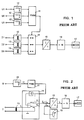
- the prior-art static kwh meter shown in Figs. 1 and 2 comprises voltage dividers 12 and current measurement transformers 13, which are connected to the wires of the electricity network so as to generate measurement signals U u , I i proportional to the voltage U and to the current I, and a multiplier circuit 11,14 to form a pulse-width/pulse-height modulated signal which represents the product of the measurement signals.
- the analog connectors K1 and K2 placed in the secondary circuit of the current measurement transformers 13 are controlled, and from the outputs of said connectors K1 and K2 pulses are received, whose height is proportional to the current flowing in the measurement current circuit and whose width is still modulated by the mains voltage.
- the pulses are filtered, whereby a direct current I p proportional to the power is obtained, which direct current is fed to the current-frequency converter 15.
- a pulse frequency f p is obtained, which is proportional to the direct current I p , i.e. to the power, which pulse frequency f p is passed through the divider unit 16 to the stepping motor that operates the counter device 17 of the meter.
- the counter device 17 integrates the power, i.e. displays the energy consumed.
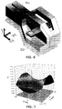
- Fig. 3 illustrates a mode of manufacture of a gradiometer of the second order, which is sensitive to a magnetic field of parabolic form only.
- the gradiometer consists of a narrow (1...5 ⁇ m) and thin (0.1...2 ⁇ m) conductor, which circulates as spiral-shaped in one or several planes and forms an antenna construction.
- the gradiometer 20a of the second order which is made of a mask 20, may consist, for example, of three coils 21,22 and 23, in which the areas of all of the coils are equal, but the number of windings in the middle coil 21 is twice as high as the number of windings in the lateral coils 22 and 23.
- the coils are connected so that the homogeneous magnetic field that changes in a linear way as a function of place does not induce a voltage in the output of the gradiometer.
- the base for example a silicon substrate
- the output terminals with the reference numeral 24.
- a gradiometer of the first order may be composed of two coils whose centre points are placed at a distance of about 2...5 mm from one another.
- the size of the coils measured from the outer edge is about (1...4 mm) x (1...4 mm), and the number of windings is 100...300.
- the current conductor is shaped appropriately, it is possible to produce distributions of magnetic field of different shapes in its direct vicinity. For example, if a rectangular conductor is split at both ends, a conductor construction 30 as shown in Fig. 4 is obtained, which produces a parabolic distribution of magnetic field as shown in Fig. 5 in the middle of the conductor 30. If a gradiometer 20a of the second order is installed in the middle of such a conductor 30, the current flowing in the conductor 30 induces a voltage in it. With a suitable choice of the shape of the conductor and the shape of the gradiometer, a situation is formed in which the place of the gradiometer has no significant effect on the output of the gradiometer.
- the conductor is shaped appropriately and if the gradiometer is composed of a number of coils, a current detector is provided whose place does not affect the output voltage of the detector. In this way, it is possible to eliminate the effect of temperature or ageing on inaccuracy of measurement. Since the conductor is made of a metal, its thermal expansion coefficient is low.
- the gradiometer can, for example, be cast in the interior of the conductor so that it remains reasonably well in the "middle" of the current conductor.
- Fig. 6 is an axonometric view of a preferred embodiment of a measurement detector in accordance with the invention.
- Fig. 6 shows a single-phase embodiment, and the current conductor is denoted with the reference numeral 30a.
- the current conductor 30a In the "middle" of the current conductor 30a, a gradiometer 20a of the second order is fitted.
- Fig. 7 is a graphic illustration of the way in which the output voltage U of a measurement detector as shown in Fig. 6 depends on the place of the gradiometer in relation to the X and Y axes.
- Figs. 8a and 8b are schematic illustrations of the use of a measurement detector in accordance with the present invention for measurement of three-phase current.
- the number of conductors 30a is three, one for each phase current I R ,I S and I T .
- a gradiometer 40a of the second order is fitted, which consists of four coils 41,42,43 and 44.
- a three-phase kilowatt-hour meter can be constructed, for example, by means of one microcircuit.
- Fig. 8a shows an arrangement in which there are four coils equal to one another as uniformly spaced.
- the voltages induced in the coils can be expressed by means of the phase currents I R , I S and I T and of the density B(x) of the outside magnetic flux as follows:
- U 1 ⁇ I R + ⁇ B(x 1 )
- U 2 - ⁇ I R + ⁇ I S + ⁇ B(x 2 )
- U 3 - ⁇ I S + ⁇ I T + ⁇ B(x 3 )
- U 4 - ⁇ I T + ⁇ B(x 4 )
- ⁇ and ⁇ are invariables determined from the conductor and gradiometer structures.
- Fig. 8a shows a magnetic shield 31 around the detector and an electric shield 32 between the current conductors and the other parts of the detector.
- the electric shield 32 which may consist, for example, of thin metal, prevents capacitive connection of the mains voltage.
- Fig. 9 shows a simplified circuitry diagram of the current measurement unit of a three-phase kwh meter.
- the voltages U1,U2,U3 and U4 of the four coils 41,42,43 and 44 are summed together so that the effect of the homogeneous field is neutralized in the differential voltages U I R , U I S and U I T . This is achieved by connecting the successive coils to opposite phases.
- the outputs of the pre-amplifiers 45 are summed with one another by means of the amplifiers 46 so that three voltages U I R* U I S* and U I T* are obtained, which are directly proportional to the phase currents. It is also possible to form differences and sums of voltages and to multiply them by a combination of the phase currents. By means of a suitable arrangement, also in this way, a situation can be produced in which exclusively terms of products of phase currents and of voltages corresponding to them are present in the overall power.
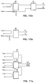
- a microcircuit in accordance with the invention contained in an integrated current detector is denoted with the reference numeral 50.
- the microcircuit 50 measures a single-phase phase current I R , and the output of the microcircuit 50 is passed to the multiplier 51.
- the voltage U R of the single-phase alternating current is passed through the voltage divider to the multiplier 51.
- the output of the multiplier 51 is the power P or the parasitic power Q.
- the microcircuit 50 measures a single-phase alternating current I R .
- the voltage U R of the single-phase alternating current is passed to the microcircuit 50 likewise through the voltage divider.
- the output of the microcircuit 50 is directly either the power P or the parasitic power Q.
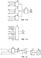
- each phase current I R , I S and I T of the three-phase kwh meter is passed to act upon a separate microcircuit 50 of its own.
- the voltages U R ,U S and U T are passed to the middle microcircuit 50.
- the output of the first microcircuit 50 and the output of the third microcircuit 50 are passed to the middle microcircuit 50.
- the output of the middle microcircuit 50 is either ⁇ P or ⁇ Q.
- each phase voltage U R , U S and U T of the alternating current is passed to a microcircuit 50 of its own.
- the outputs of the microcircuits 50 are passed to the multiplier 51.
- the output of the multiplier 51 is either ⁇ P or ⁇ Q.
- the three-phase kwh meter is an integrated circuit, which permits simultaneous detection of all the phase currents I R , I S and I T .
- Each phase voltage U R , U S and U T of the alternating current is passed to one and the same microcircuit 50.
- the output of the microcircuit 50 is either ⁇ P or ⁇ Q.
- the output voltage of the current detector is directly proportional to the derivative of current in relation to time. If the shortest distance from the conductor is about 3 mm and the size of the detector shown in Fig. 3 is about 7 mm x 3 mm and the number of windings in the middle coil 21 is about 220 and the number of windings in the lateral coils 22 and 23 is about 110, the induction voltage that is obtained is about 5 ⁇ V with a current of 1A. If the noise of the amplifier is about 15 nV and the thermal noise of the resistances of the coil is about 15 nV, with an integration time constant of one second, the sensitivity becomes about 5 mA. In other words, the dynamic range of the detector can be even 5 mA ... 200 A.
- the maximal value of current is determined mainly by the heating of the conductor.
- the amplifier can either have a fixed amplification, or the amplification can be made adjustable.
- an integrator 26 can be added to the microcircuit 50, the phase of the output voltage of said integrator 26 being the same as the phase of the current to be measured. Such a solution is illustrated in Fig. 12.
- an additional amplifier 25, an integrator 26, a multiplier 27, and a voltage-frequency converter 28 can be integrated.
- the voltage can be monitored either directly from the microcircuit 50 capacitively or by feeding the voltage through a resistor to the microcircuit 50.
- the current detector permits integration of the whole kwh meter in one microcircuit 50.
- a three-phase kwh meter requires three separate microcircuits 50. It is also possible to manufacture a long, for example (8...14 mm) and thin (3...4 mm) integrated circuit 50, which permits simultaneous detection of all the phase currents. This permits the manufacture of a highly advantageous three-phase kwh meter.
- the invention concerns a method for measurement of alternating current, a measurement detector meant for measurement of alternating current, and the use of such a measurement detector in a kwh meter.
- a gradiometer of at least the first order is fitted, in which case the current that flows in the current conductor system (30a) induces a voltage in the gradiometer, and that the shape of the current conductor system (30a) and the shape of the coil construction of the gradiometer (20a) are adapted to one another so that the output signal is substantially independent from any little changes taking place in the relative positions of the current conductor system (30a) and the gradiometer (20a).
Abstract
Description
- The invention concerns a method for measurement of alternating current.
- Further, the invention concerns an integrated current detector for measurement of alternating current.
- In a kwh meter, measurement of current requires high dynamism (10 mA...200 A), good resistance to interference, good linearity, and the detector must tolerate any direct current that may be present in a conductor. Measurement of current is most commonly based on resistance, which converts the current to voltage, on a current transformer with an iron or ferrite core, on an induction phenomenon, in which the primary current induces a voltage in the secondary coil, on magnetic detectors (such as a Hall detector or a magneto-resistive detector), or, in some cases, on an optical fibre that senses the magnetic field. In all the detectors, except that based on resistance, the measurement is, in one way or another, based on utilization of the magnetic field produced by the current. The different methods are associated with good and bad features. A traditional current transformer is spacious and does not tolerate direct current, so that, in modern kwh meters, its use is being abandoned.
- The object of the present invention is to provide an improvement over the prior-art methods for measurement of alternating current and to provide a measurement detector meant for measurement of alternating current and excellently suitable for use in kwh meters.
- The objects of the invention are achieved by means of a method which is characterized in that, in the method, inside the current conductor system or in direct vicinity of said system, a gradiometer of at least the first order is fitted, in which case the current that flows in the current conductor system induces a voltage in the gradiometer, and that the shape of the current conductor system and the shape of the coil construction of the gradiometer are adapted to one another so that the output signal is substantially independent from any little changes taking place in the relative positions of the current conductor system and the gradiometer.
- The measurement detector in accordance with the present invention and meant for measurement of alternating current is characterized in that the current detector consists of a current conductor system and of a gradiometer fitted inside or in direct vicinity of said conductor system, and that a pre-amplifier/pre-amplifiers is/are fitted in direct vicinity of the outputs of the gradiometer.
- In the present patent application, the definitions "in direct vicinity of the current conductor system" and "in direct vicinity of the outputs of the gradiometer" mean a distance that is proportional to the sizes of the gradiometer and of a portion of the conductor. The size of the gradiometer can be of an order of 5...10 mm, and the size of the cross-section of a portion of the conductor may be of an order of 1...5 mm. Thus, direct vicinity means a distance that is smaller than, or equal to, the largest dimension of the gradiometer.
- The pre-amplifier may be, for example, integrated on the same silicon chip as the gradiometer, or the pre-amplifier may be placed in a separate circuit, installed, for example, by means of the flip-chip technique on the gradiometer.
- The gradiometer can be accomplished by connecting the coils and by using one common pre-amplifier, or by amplifying the signals of the coils separately by means of pre-amplifiers of their own and by interconnecting the amplified signals. The gradiometer may also be a combination of the wirings described above.
- In the method of the present invention, onto a base, such as, for example, silicon, a gradiometer of the nth order is grown. If high currents and voltages are concerned, the gradiometer is a gradiometer of either first or second order. When low currents and voltages are concerned, the gradiometer may perhaps be a gradiometer of third, fourth, of fifth or even sixth order. Of course, when the order becomes higher, the system becomes more complicated.
- The present-day technique of manufacture of masks permits an integration of gradiometer coils so that the attenuation, for example, with a homogeneous field can be made very high (higher than 1000). The manufacture of masks is based on a laser exposer, whose location is determined by means of a laser interferometer, which permits an inaccuracy of location below 0.5 µm. By means of masks it is possible to produce line widths even of an order of 1 µm, but the width of the ultimate conductor is determined in the process of manufacture. A present, a realistic width of a conductor is about 1...3 µm.
- Since the detector includes a gradiometer, it is insensitive to a homogeneous magnetic field. If a gradiometer of the second order is used, the detector is also insensitive to a field that changes linearly as a function of place. In other words, the current detector is not disturbed even by an intensive field of interference. Since the detector is based on the induction phenomenon, a DC-magnetic field arising in a direct current in the current conductor or an outside DC-field does not affect the operation of the detector. If the attenuation of interference in the detector is not sufficient, it is possible to install a magnetic shield around the detector to provide additional attenuation.
- The coils in a gradiometer of the second order may consist of three coils whose areas are equal but in which the number of windings in the middle coil is twice as high as the number of windings in the lateral coils. In such a case, the number of windings in the middle coil is preferably in a range of 10...1000. The areas of the coils are preferably in the range of 1...30 mm².
- The invention will be described in detail with reference to some preferred embodiments of the invention shown in the figures in the accompanying drawing, the invention being, yet, not supposed to be confined to said embodiments alone.
- Figure 1 illustrates a prior-art static kwh meter as a block diagram.
- Figure 2 shows a prior-art static kwh meter as a block diagram, wherein the switching arrangement of the multiplier circuit is shown in more detail in respect of one phase.
- Figure 3 is a schematic illustration of a mask on which a gradiometer of the second order has been formed, viewed from above.
- Figure 4 is an axonometric view of a preferred embodiment of a current conductor, which is suitable for use with a gradiometer of the second order as shown in Fig. 3.
- Figure 5 is a graphic illustration of the form of the magnetic field of the current conductor shown in Fig. 4.
- Figure 6 is an axonometric view of a preferred embodiment of the measurement detector in accordance with the invention.
- Figure 7 is a graphic illustration of the output voltage of the measurement detector as shown in Fig. 6.
- Figure 8a is a schematic illustration of the use of a measurement detector in accordance with the invention for measurement of three-phase current, viewed from above.
- Figure 8b is a side view of the measurement detector arrangement shown in Fig. 8a.
- Figure 9 is a schematic illustration of a simplified circuit diagram of a current measurement unit of a three-phase kwh meter.
- Fig. 10a is a schematic illustration of a measurement wiring when a current detector in accordance with the invention is used in a 1-phase kwh meter.
- Figure 10b is a schematic illustration of a second measurement wiring when a current detector in accordance with the invention is used in a 1-phase kwh meter.
- Figure 11a is a schematic illustration of a measurement wiring when a current detector in accordance with the invention is used in a 3-phase kwh meter.
- Figure 11b is a schematic illustration of a second measurement wiring when a current detector in accordance with the invention is used in a 3-phase kwh meter.
- Figure 11c is a schematic illustration of a third measurement wiring when a current detector in accordance with the invention is used in a 3-phase kwh meter.
- Figure 12 shows a schematic block diagram of an application of use of a measurement detector in accordance with the invention in a kwh meter.
- The prior-art static kwh meter shown in Figs. 1 and 2 comprises
voltage dividers 12 andcurrent measurement transformers 13, which are connected to the wires of the electricity network so as to generate measurement signals Uu, Ii proportional to the voltage U and to the current I, and amultiplier circuit width modulator 11, the analog connectors K₁ and K₂ placed in the secondary circuit of thecurrent measurement transformers 13 are controlled, and from the outputs of said connectors K₁ and K₂ pulses are received, whose height is proportional to the current flowing in the measurement current circuit and whose width is still modulated by the mains voltage. The pulses are filtered, whereby a direct current Ip proportional to the power is obtained, which direct current is fed to the current-frequency converter 15. - Thus, from the output of the current-
frequency converter 15, a pulse frequency fp is obtained, which is proportional to the direct current Ip, i.e. to the power, which pulse frequency fp is passed through thedivider unit 16 to the stepping motor that operates thecounter device 17 of the meter. Thecounter device 17 integrates the power, i.e. displays the energy consumed. - By the effect of the switching pulses, an extra DC component IE is produced in the measurement circuit, which component deteriorates the accuracy of measurement in particular when the current to be measured is low. In the solution of Fig. 2, the DC component IE is compensated for by an
external regulation member 18, from which a current -IE of opposite sign and of equal magnitude is fed to the current-frequency converter 15. - Fig. 3 illustrates a mode of manufacture of a gradiometer of the second order, which is sensitive to a magnetic field of parabolic form only. The gradiometer consists of a narrow (1...5 µm) and thin (0.1...2 µm) conductor, which circulates as spiral-shaped in one or several planes and forms an antenna construction. The
gradiometer 20a of the second order, which is made of amask 20, may consist, for example, of threecoils middle coil 21 is twice as high as the number of windings in thelateral coils reference numeral 19 and the output terminals with thereference numeral 24. - A gradiometer of the first order may be composed of two coils whose centre points are placed at a distance of about 2...5 mm from one another. The size of the coils measured from the outer edge is about (1...4 mm) x (1...4 mm), and the number of windings is 100...300.
- If the current conductor is shaped appropriately, it is possible to produce distributions of magnetic field of different shapes in its direct vicinity. For example, if a rectangular conductor is split at both ends, a
conductor construction 30 as shown in Fig. 4 is obtained, which produces a parabolic distribution of magnetic field as shown in Fig. 5 in the middle of theconductor 30. If agradiometer 20a of the second order is installed in the middle of such aconductor 30, the current flowing in theconductor 30 induces a voltage in it. With a suitable choice of the shape of the conductor and the shape of the gradiometer, a situation is formed in which the place of the gradiometer has no significant effect on the output of the gradiometer. In other words, if the conductor is shaped appropriately and if the gradiometer is composed of a number of coils, a current detector is provided whose place does not affect the output voltage of the detector. In this way, it is possible to eliminate the effect of temperature or ageing on inaccuracy of measurement. Since the conductor is made of a metal, its thermal expansion coefficient is low. The gradiometer can, for example, be cast in the interior of the conductor so that it remains reasonably well in the "middle" of the current conductor. - Fig. 6 is an axonometric view of a preferred embodiment of a measurement detector in accordance with the invention. Fig. 6 shows a single-phase embodiment, and the current conductor is denoted with the
reference numeral 30a. In the "middle" of thecurrent conductor 30a, agradiometer 20a of the second order is fitted. - Fig. 7 is a graphic illustration of the way in which the output voltage U of a measurement detector as shown in Fig. 6 depends on the place of the gradiometer in relation to the X and Y axes.
- Figs. 8a and 8b are schematic illustrations of the use of a measurement detector in accordance with the present invention for measurement of three-phase current. The number of
conductors 30a is three, one for each phase current IR,IS and IT. Inside the current-conductor system 30a, agradiometer 40a of the second order is fitted, which consists of fourcoils - A three-phase kilowatt-hour meter can be constructed, for example, by means of one microcircuit. Fig. 8a shows an arrangement in which there are four coils equal to one another as uniformly spaced. The voltages induced in the coils can be expressed by means of the phase currents IR, IS and IT and of the density B(x) of the outside magnetic flux as follows:

- The coils are installed in connection with one another so that the following differences are formed:

- If it is assumed that the density of the outside magnetic flux is of the form

- It is noticed that the homogeneous magnetic field is eliminated, but the gradient of the outside field remains. Since the coils have been fitted as uniformly spaced ℓ, and if the origin is placed at the middle conductor, what is obtained is:

- Now it is possible to write the voltages in the form:

- The following voltages are formed:

- When these voltages are multiplied by the corresponding phase voltages and summed up, what is obtained is:

magnetic shield 31 around the detector and anelectric shield 32 between the current conductors and the other parts of the detector. Theelectric shield 32, which may consist, for example, of thin metal, prevents capacitive connection of the mains voltage. - Fig. 9 shows a simplified circuitry diagram of the current measurement unit of a three-phase kwh meter. The voltages U₁,U₂,U₃ and U₄ of the four
coils 


pre-amplifiers 45 are summed with one another by means of theamplifiers 46 so that three voltages U


- In Fig. 10a, a microcircuit in accordance with the invention contained in an integrated current detector is denoted with the
reference numeral 50. Themicrocircuit 50 measures a single-phase phase current IR, and the output of themicrocircuit 50 is passed to themultiplier 51. The voltage UR of the single-phase alternating current is passed through the voltage divider to themultiplier 51. The output of themultiplier 51 is the power P or the parasitic power Q. - In the embodiment as shown in Fig. 10b, the
microcircuit 50 measures a single-phase alternating current IR. The voltage UR of the single-phase alternating current is passed to themicrocircuit 50 likewise through the voltage divider. The output of themicrocircuit 50 is directly either the power P or the parasitic power Q. - In the embodiment shown in Fig. 11a, each phase current IR, IS and IT of the three-phase kwh meter is passed to act upon a
separate microcircuit 50 of its own. The voltages UR,US and UT are passed to themiddle microcircuit 50. The output of thefirst microcircuit 50 and the output of thethird microcircuit 50 are passed to themiddle microcircuit 50. The output of themiddle microcircuit 50 is either ΣP or ΣQ. - In the embodiment shown in Fig. 11b, each phase voltage UR, US and UT of the alternating current is passed to a
microcircuit 50 of its own. The outputs of themicrocircuits 50 are passed to themultiplier 51. The output of themultiplier 51 is either ΣP or ΣQ. - In the embodiment shown in Fig. 11c, the three-phase kwh meter is an integrated circuit, which permits simultaneous detection of all the phase currents IR, IS and IT. Each phase voltage UR, US and UT of the alternating current is passed to one and the
same microcircuit 50. The output of themicrocircuit 50 is either ΣP or ΣQ. - The output voltage of the current detector is directly proportional to the derivative of current in relation to time. If the shortest distance from the conductor is about 3 mm and the size of the detector shown in Fig. 3 is about 7 mm x 3 mm and the number of windings in the
middle coil 21 is about 220 and the number of windings in the lateral coils 22 and 23 is about 110, the induction voltage that is obtained is about 5 µV with a current of 1A. If the noise of the amplifier is about 15 nV and the thermal noise of the resistances of the coil is about 15 nV, with an integration time constant of one second, the sensitivity becomes about 5 mA. In other words, the dynamic range of the detector can be even 5 mA ... 200 A. The maximal value of current is determined mainly by the heating of the conductor. The amplifier can either have a fixed amplification, or the amplification can be made adjustable. After theamplifier 25, anintegrator 26 can be added to themicrocircuit 50, the phase of the output voltage of saidintegrator 26 being the same as the phase of the current to be measured. Such a solution is illustrated in Fig. 12. - As is shown in Fig. 12, in connection with the current detector in accordance with the invention, an
additional amplifier 25, anintegrator 26, amultiplier 27, and a voltage-frequency converter 28 can be integrated. Thus, all the parts of the kwh meter can be integrated in the same microcircuit. The voltage can be monitored either directly from themicrocircuit 50 capacitively or by feeding the voltage through a resistor to themicrocircuit 50. The current detector permits integration of the whole kwh meter in onemicrocircuit 50. In principle, a three-phase kwh meter requires threeseparate microcircuits 50. It is also possible to manufacture a long, for example (8...14 mm) and thin (3...4 mm) integratedcircuit 50, which permits simultaneous detection of all the phase currents. This permits the manufacture of a highly advantageous three-phase kwh meter. - Above, just some preferred embodiments of the invention have been described, and it is obvious to a person skilled in the art that numerous modifications can be made to said embodiments within the scope of the inventive idea disclosed in the accompanying patent claims.
- The invention concerns a method for measurement of alternating current, a measurement detector meant for measurement of alternating current, and the use of such a measurement detector in a kwh meter. In the method, inside the current conductor system (30a) or in direct vicinity of said system, a gradiometer of at least the first order is fitted, in which case the current that flows in the current conductor system (30a) induces a voltage in the gradiometer, and that the shape of the current conductor system (30a) and the shape of the coil construction of the gradiometer (20a) are adapted to one another so that the output signal is substantially independent from any little changes taking place in the relative positions of the current conductor system (30a) and the gradiometer (20a).
(FIG. 6)
Claims (17)
- A method for measurement of alternating current, characterized in that, in the method, inside the current conductor system (30,30a) or in direct vicinity of said system, a gradiometer of at least the first order is fitted, in which case the current that flows in the current conductor system (30,30a) induces a voltage in the gradiometer, and that the shape of the current conductor system (30,30a) and the shape of the coil construction (21,22,23) of the gradiometer (20a) are adapted to one another so that the output signal is substantially independent from any little changes taking place in the relative positions of the current conductor system (30,30a) and the gradiometer (20a).
- A method as claimed in claim 1, characterized in that a gradiometer of the first order is used as the gradiometer.
- A method as claimed in claim 1, characterized in that a gradiometer (20a) of the second order is used as the gradiometer.
- A method as claimed in claim 1, characterized in that a gradiometer of the nth order is used as the gradiometer, wherein n is 3,4,5 or 6.
- An integrated current detector for measurement of alternating current, characterized in that the current detector consists of a current conductor system (30,30a) and of a gradiometer (20a) fitted inside or in direct vicinity of said conductor system, and that a pre-amplifier/pre-amplifiers is/are fitted in direct vicinity of the outputs of the gradiometer.
- A current detector as claimed in claim 5, characterized in that the coils of the gradiometer (20a) of at least the second order consist of at least three coils (21,22,23), whose areas are equal but in which the number of windings in the middle coil (21) is twice as high as the number of windings in the lateral coils (22,23).
- A current detector as claimed in claim 6, characterized in that the number of windings in the middle coil (21) is in a range of 10...1000.
- A current detector as claimed in claim 5 or 7, characterized in that the areas of the coils (21,22,23) are in a range of 1...30 mm².
- A current detector as claimed in any of the claims 5 to 8, characterized in that, in the current detector, an additional amplifier (25), an integrator (26), a multiplier (27), and a voltage-frequency converter (28) have been fitted.
- A current detector as claimed in any of the claims 5 to 9, characterized in that the current conductor (30) consists of a rectangular conductor, which has been split at both ends, the current-conductor construction producing a magnetic distribution of parabolic form in the middle of the current conductor.
- A current detector as claimed in any of the claims 5 to 10, characterized in that between the current conductors and the other parts of the detector, there is a thin electrically conductive layer (32).
- A current detector as claimed in any of the claims 5 to 11, characterized in that a magnetic shield (31) has been fitted around the detector.
- A current detector as claimed in any of the claims 5 to 12, characterized in that the dynamic range of the current detector is in the range of 5 mA ... 200 A.
- The use of a current detector as claimed in any of the claims 5 to 13 in a single-phase kwh meter.
- A kwh meter in which there is a current detector as claimed in any of the claims 5 to 13, characterized in that each phase current (IR,IS,IT) in the three-phase kwh meter is connected to a separate microcircuit (50) of its own.
- A kwh meter in which there is a current detector as claimed in any of the claims 5 to 13, characterized in that the three-phase kwh meter is an integrated microcircuit (50) which permits simultaneous detection of all the phase currents (IR,IS,IT).
- A kwh meter as claimed in claims 15 or 16, characterized in that the gradiometer (40a) of the second order consists of four coils (41,42,43,44), and that successive coils that are to be summed up are connected to opposite phases, whereby the effect of a homogeneous field is neutralized.
Applications Claiming Priority (2)
| Application Number | Priority Date | Filing Date | Title |
|---|---|---|---|
| FI945232A FI98865C (en) | 1994-11-07 | 1994-11-07 | Method for measuring alternating current, measuring sensor for measuring alternating current and its use in a kWh meter |
| FI945232 | 1994-11-07 |
Publications (3)
| Publication Number | Publication Date |
|---|---|
| EP0710844A2 true EP0710844A2 (en) | 1996-05-08 |
| EP0710844A3 EP0710844A3 (en) | 1996-07-31 |
| EP0710844B1 EP0710844B1 (en) | 2002-05-22 |
Family
ID=8541745
Family Applications (1)
| Application Number | Title | Priority Date | Filing Date |
|---|---|---|---|
| EP95115801A Expired - Lifetime EP0710844B1 (en) | 1994-11-07 | 1995-10-06 | Method of measuring an alternating current, measurement detector for measurement of alternating current, and use of said detector in a kWh meter |
Country Status (6)
| Country | Link |
|---|---|
| EP (1) | EP0710844B1 (en) |
| AT (1) | ATE217976T1 (en) |
| DE (1) | DE69526774T2 (en) |
| DK (1) | DK0710844T3 (en) |
| ES (1) | ES2177597T3 (en) |
| FI (1) | FI98865C (en) |
Cited By (13)
| Publication number | Priority date | Publication date | Assignee | Title |
|---|---|---|---|---|
| EP0874244A2 (en) * | 1997-04-19 | 1998-10-28 | LUST ANTRIEBSTECHNIK GmbH | Procedure and apparatus for measuring electric currents in conductors |
| EP0893696A2 (en) * | 1997-07-24 | 1999-01-27 | Robert Bosch Gmbh | Arrangement for measuring an AC current |
| DE19740428A1 (en) * | 1997-09-10 | 1999-03-18 | Siemens Ag | Current transformer toroidal coil with circular winding cross-section |
| EP0947843A2 (en) * | 1998-03-28 | 1999-10-06 | ABB Research Ltd. | Current measuring method |
| WO2001011376A1 (en) * | 1999-08-06 | 2001-02-15 | Sentec Ltd. | Current sensor |
| WO2001014894A1 (en) * | 1999-08-24 | 2001-03-01 | Siemens Metering Limited | Sensor for current measurement and electricity meter |
| DE10011047A1 (en) * | 2000-03-07 | 2001-09-27 | Vacuumschmelze Gmbh | Direct imaging current sensor has additional winding that covers certain regions and magnetic flow of the soft magnetic core |
| DE10045194A1 (en) * | 2000-09-13 | 2002-03-28 | Siemens Ag | Evaluation circuit for a current sensor based on the principle of compensation, in particular for measuring direct and alternating currents, and method for operating such a current sensor |
| DE10100597A1 (en) * | 2001-01-09 | 2002-07-18 | Bosch Gmbh Robert | Device, ammeter and motor vehicle |
| US6434138B2 (en) | 1996-05-08 | 2002-08-13 | Robert Bosch Gmbh | Process for transmitting messages by digital sound broadcasting and receiver for carrying out this process |
| EP1295304A1 (en) | 2000-05-05 | 2003-03-26 | Enermet Oy | Current transformer for measurement of alternating current |
| EP1666893A1 (en) * | 2004-12-04 | 2006-06-07 | Landis+Gyr AG | Integrated device for AC-current measurement |
| DE10045670B4 (en) * | 1999-09-17 | 2008-08-07 | Yazaki Corp. | Current detection device and current detection method |
Families Citing this family (2)
| Publication number | Priority date | Publication date | Assignee | Title |
|---|---|---|---|---|
| FI110964B (en) * | 2000-08-18 | 2003-04-30 | Enermet Oy | Method and apparatus for measuring power in an AC system |
| EP3385727A1 (en) * | 2017-04-07 | 2018-10-10 | Siemens Aktiengesellschaft | Method for measuring a current and current measurement device |
Family Cites Families (1)
| Publication number | Priority date | Publication date | Assignee | Title |
|---|---|---|---|---|
| DE4125087C2 (en) * | 1991-07-29 | 2000-03-30 | Siemens Ag | Measuring device with a field-sensitive gradiometer loop arrangement and integrated DC SQUID |
-
1994
- 1994-11-07 FI FI945232A patent/FI98865C/en not_active IP Right Cessation
-
1995
- 1995-10-06 AT AT95115801T patent/ATE217976T1/en not_active IP Right Cessation
- 1995-10-06 DE DE69526774T patent/DE69526774T2/en not_active Expired - Lifetime
- 1995-10-06 EP EP95115801A patent/EP0710844B1/en not_active Expired - Lifetime
- 1995-10-06 DK DK95115801T patent/DK0710844T3/en active
- 1995-10-06 ES ES95115801T patent/ES2177597T3/en not_active Expired - Lifetime
Non-Patent Citations (1)
| Title |
|---|
| None |
Cited By (25)
| Publication number | Priority date | Publication date | Assignee | Title |
|---|---|---|---|---|
| US6434138B2 (en) | 1996-05-08 | 2002-08-13 | Robert Bosch Gmbh | Process for transmitting messages by digital sound broadcasting and receiver for carrying out this process |
| EP0874244A3 (en) * | 1997-04-19 | 1999-03-31 | LUST ANTRIEBSTECHNIK GmbH | Procedure and apparatus for measuring electric currents in conductors |
| EP0874244A2 (en) * | 1997-04-19 | 1998-10-28 | LUST ANTRIEBSTECHNIK GmbH | Procedure and apparatus for measuring electric currents in conductors |
| US6310470B1 (en) | 1997-04-19 | 2001-10-30 | Lust Antriebstechnik Gmbh | Method and device for measuring the difference in magnetic field strength with magnetoresistive sensors |
| EP0893696A2 (en) * | 1997-07-24 | 1999-01-27 | Robert Bosch Gmbh | Arrangement for measuring an AC current |
| DE19731790A1 (en) * | 1997-07-24 | 1999-01-28 | Bosch Gmbh Robert | Device for detecting an alternating current |
| EP0893696A3 (en) * | 1997-07-24 | 1999-05-06 | Robert Bosch Gmbh | Arrangement for measuring an AC current |
| DE19740428C2 (en) * | 1997-09-10 | 2001-03-08 | Siemens Ag | Annular coil with circular winding cross-section and process for its production |
| DE19740428A1 (en) * | 1997-09-10 | 1999-03-18 | Siemens Ag | Current transformer toroidal coil with circular winding cross-section |
| EP0947843A2 (en) * | 1998-03-28 | 1999-10-06 | ABB Research Ltd. | Current measuring method |
| EP0947843A3 (en) * | 1998-03-28 | 2000-12-27 | ABB Research Ltd. | Current measuring method |
| WO2001011376A1 (en) * | 1999-08-06 | 2001-02-15 | Sentec Ltd. | Current sensor |
| US6414475B1 (en) | 1999-08-06 | 2002-07-02 | Sentec Ltd. | Current sensor |
| WO2001014894A1 (en) * | 1999-08-24 | 2001-03-01 | Siemens Metering Limited | Sensor for current measurement and electricity meter |
| AU764263B2 (en) * | 1999-08-24 | 2003-08-14 | Landis & Gyr Limited | Sensor for current measurement and electricity meter |
| DE10045670B4 (en) * | 1999-09-17 | 2008-08-07 | Yazaki Corp. | Current detection device and current detection method |
| DE10011047A1 (en) * | 2000-03-07 | 2001-09-27 | Vacuumschmelze Gmbh | Direct imaging current sensor has additional winding that covers certain regions and magnetic flow of the soft magnetic core |
| DE10011047B4 (en) * | 2000-03-07 | 2010-04-15 | Vacuumschmelze Gmbh | Direct imaging current sensor |
| EP1295304A1 (en) | 2000-05-05 | 2003-03-26 | Enermet Oy | Current transformer for measurement of alternating current |
| DE10045194A1 (en) * | 2000-09-13 | 2002-03-28 | Siemens Ag | Evaluation circuit for a current sensor based on the principle of compensation, in particular for measuring direct and alternating currents, and method for operating such a current sensor |
| US6990415B2 (en) | 2000-09-13 | 2006-01-24 | Siemens Aktiengesellschaft | Evaluation circuit for a current sensor using the compensation principle, in particular for measuring direct and alternating currents, and a method for operating such a current sensor |
| DE10100597A1 (en) * | 2001-01-09 | 2002-07-18 | Bosch Gmbh Robert | Device, ammeter and motor vehicle |
| EP1666893A1 (en) * | 2004-12-04 | 2006-06-07 | Landis+Gyr AG | Integrated device for AC-current measurement |
| WO2006059218A2 (en) * | 2004-12-04 | 2006-06-08 | Landis+Gyr Ag | Integrated device for measuring an alternating current |
| WO2006059218A3 (en) * | 2004-12-04 | 2007-11-01 | Landis & Gyr Ag | Integrated device for measuring an alternating current |
Also Published As
| Publication number | Publication date |
|---|---|
| ES2177597T3 (en) | 2002-12-16 |
| FI945232A (en) | 1996-05-08 |
| DE69526774T2 (en) | 2002-11-21 |
| FI945232A0 (en) | 1994-11-07 |
| EP0710844B1 (en) | 2002-05-22 |
| DK0710844T3 (en) | 2002-08-26 |
| EP0710844A3 (en) | 1996-07-31 |
| FI98865C (en) | 1997-08-25 |
| ATE217976T1 (en) | 2002-06-15 |
| FI98865B (en) | 1997-05-15 |
| DE69526774D1 (en) | 2002-06-27 |
Similar Documents
| Publication | Publication Date | Title |
|---|---|---|
| US4413230A (en) | Electric energy meter having a mutual inductance current transducer | |
| EP0710844A2 (en) | Method for measurement of alternating current, measurement detector for measurement of alternating current, and use of SAID detector in a KWH meter | |
| US4491790A (en) | Electric energy meter having a mutual inductance current transducer | |
| CA2380934C (en) | Current sensor | |
| US4240059A (en) | Current divider for a current sensing transducer | |
| EP0718635B1 (en) | An electrical metering system having an electrical meter and an external current sensor | |
| US7274186B2 (en) | Temperature compensated and self-calibrated current sensor | |
| CA2141128C (en) | Method and apparatus for sensing an input current with a bridge circuit | |
| US4182982A (en) | Current sensing transducer for power line current measurements | |
| US4504787A (en) | Electronic watthour meter | |
| US4368424A (en) | Mutual inductance current transducer for AC electric energy meters | |
| EP0627630A2 (en) | Differential current sensing method and apparatus | |
| Ward | Measurement of current using Rogowski coils | |
| Ren | A 100000-A high precision on-site measurement calibration device for heavy direct current | |
| Chen et al. | Replacing current transformers with power current microsensors based on hall ICs without iron cores | |
| GB2026175A (en) | Electric energy meter having a current-sensing transformer | |
| CA1181133A (en) | Electric energy meter having a mutual inductance current transducer | |
| GB2154806A (en) | Clip-on current measuring device | |
| EP1208386B1 (en) | Sensor for current measurement and electricity meter | |
| JPH0261710B2 (en) | ||
| Fam | A combined current voltage sensor for metering and protection in high voltage power systems | |
| Velasco-Quesada et al. | 12 Technologies for Electric Current Sensors | |
| AU2001100615A4 (en) | Terminal arrangement for electricity meter | |
| N-Nagy et al. | Hall-effect wattmeter for measuring iron losses at high flux densities in a single Epstein sample | |
| Kühn | The measurement of current in a transmission line by remote electromagnetic field sensing |
Legal Events
| Date | Code | Title | Description |
|---|---|---|---|
| PUAI | Public reference made under article 153(3) epc to a published international application that has entered the european phase |
Free format text: ORIGINAL CODE: 0009012 |
|
| AK | Designated contracting states |
Kind code of ref document: A2 Designated state(s): AT BE CH DE DK ES FR GB GR IE IT LI LU MC NL PT SE |
|
| PUAL | Search report despatched |
Free format text: ORIGINAL CODE: 0009013 |
|
| AK | Designated contracting states |
Kind code of ref document: A3 Designated state(s): AT BE CH DE DK ES FR GB GR IE IT LI LU MC NL PT SE |
|
| 17P | Request for examination filed |
Effective date: 19961112 |
|
| 17Q | First examination report despatched |
Effective date: 20000405 |
|
| RTI1 | Title (correction) |
Free format text: METHOD OF MEASURING AN ALTERNATING CURRENT, MEASUREMENT DETECTOR FOR MEASUREMENT OF ALTERNATING CURRENT, AND USE OF SAID DETECTOR IN A KWH METER |
|
| GRAG | Despatch of communication of intention to grant |
Free format text: ORIGINAL CODE: EPIDOS AGRA |
|
| RTI1 | Title (correction) |
Free format text: METHOD OF MEASURING AN ALTERNATING CURRENT, MEASUREMENT DETECTOR FOR MEASUREMENT OF ALTERNATING CURRENT, AND USE OF SAID DETECTOR IN A KWH METER |
|
| RTI1 | Title (correction) |
Free format text: METHOD OF MEASURING AN ALTERNATING CURRENT, MEASUREMENT DETECTOR FOR MEASUREMENT OF ALTERNATING CURRENT, AND USE OF SAID DETECTOR IN A KWH METER |
|
| GRAG | Despatch of communication of intention to grant |
Free format text: ORIGINAL CODE: EPIDOS AGRA |
|
| GRAH | Despatch of communication of intention to grant a patent |
Free format text: ORIGINAL CODE: EPIDOS IGRA |
|
| GRAH | Despatch of communication of intention to grant a patent |
Free format text: ORIGINAL CODE: EPIDOS IGRA |
|
| GRAA | (expected) grant |
Free format text: ORIGINAL CODE: 0009210 |
|
| PG25 | Lapsed in a contracting state [announced via postgrant information from national office to epo] |
Ref country code: GR Free format text: LAPSE BECAUSE OF FAILURE TO SUBMIT A TRANSLATION OF THE DESCRIPTION OR TO PAY THE FEE WITHIN THE PRESCRIBED TIME-LIMIT Effective date: 20020522 Ref country code: BE Free format text: LAPSE BECAUSE OF FAILURE TO SUBMIT A TRANSLATION OF THE DESCRIPTION OR TO PAY THE FEE WITHIN THE PRESCRIBED TIME-LIMIT Effective date: 20020522 Ref country code: AT Free format text: LAPSE BECAUSE OF FAILURE TO SUBMIT A TRANSLATION OF THE DESCRIPTION OR TO PAY THE FEE WITHIN THE PRESCRIBED TIME-LIMIT Effective date: 20020522 |
|
| REF | Corresponds to: |
Ref document number: 217976 Country of ref document: AT Date of ref document: 20020615 Kind code of ref document: T |
|
| REG | Reference to a national code |
Ref country code: GB Ref legal event code: FG4D |
|
| REG | Reference to a national code |
Ref country code: CH Ref legal event code: EP |
|
| REG | Reference to a national code |
Ref country code: IE Ref legal event code: FG4D |
|
| REF | Corresponds to: |
Ref document number: 69526774 Country of ref document: DE Date of ref document: 20020627 |
|
| PG25 | Lapsed in a contracting state [announced via postgrant information from national office to epo] |
Ref country code: PT Free format text: LAPSE BECAUSE OF FAILURE TO SUBMIT A TRANSLATION OF THE DESCRIPTION OR TO PAY THE FEE WITHIN THE PRESCRIBED TIME-LIMIT Effective date: 20020822 |
|
| REG | Reference to a national code |
Ref country code: DK Ref legal event code: T3 |
|
| REG | Reference to a national code |
Ref country code: CH Ref legal event code: NV Representative=s name: R. A. EGLI & CO. PATENTANWAELTE |
|
| PG25 | Lapsed in a contracting state [announced via postgrant information from national office to epo] |
Ref country code: LU Free format text: LAPSE BECAUSE OF NON-PAYMENT OF DUE FEES Effective date: 20021006 |
|
| PG25 | Lapsed in a contracting state [announced via postgrant information from national office to epo] |
Ref country code: IE Free format text: LAPSE BECAUSE OF NON-PAYMENT OF DUE FEES Effective date: 20021007 |
|
| ET | Fr: translation filed | ||
| REG | Reference to a national code |
Ref country code: ES Ref legal event code: FG2A Ref document number: 2177597 Country of ref document: ES Kind code of ref document: T3 |
|
| PLBE | No opposition filed within time limit |
Free format text: ORIGINAL CODE: 0009261 |
|
| STAA | Information on the status of an ep patent application or granted ep patent |
Free format text: STATUS: NO OPPOSITION FILED WITHIN TIME LIMIT |
|
| PG25 | Lapsed in a contracting state [announced via postgrant information from national office to epo] |
Ref country code: MC Free format text: LAPSE BECAUSE OF NON-PAYMENT OF DUE FEES Effective date: 20030501 |
|
| 26N | No opposition filed |
Effective date: 20030225 |
|
| REG | Reference to a national code |
Ref country code: IE Ref legal event code: MM4A |
|
| PGFP | Annual fee paid to national office [announced via postgrant information from national office to epo] |
Ref country code: DK Payment date: 20131031 Year of fee payment: 19 |
|
| PGFP | Annual fee paid to national office [announced via postgrant information from national office to epo] |
Ref country code: FR Payment date: 20131031 Year of fee payment: 19 Ref country code: DE Payment date: 20131028 Year of fee payment: 19 Ref country code: SE Payment date: 20131031 Year of fee payment: 19 Ref country code: GB Payment date: 20131025 Year of fee payment: 19 Ref country code: CH Payment date: 20131031 Year of fee payment: 19 |
|
| PGFP | Annual fee paid to national office [announced via postgrant information from national office to epo] |
Ref country code: IT Payment date: 20131030 Year of fee payment: 19 Ref country code: NL Payment date: 20131025 Year of fee payment: 19 Ref country code: ES Payment date: 20131106 Year of fee payment: 19 |
|
| REG | Reference to a national code |
Ref country code: DE Ref legal event code: R119 Ref document number: 69526774 Country of ref document: DE |
|
| REG | Reference to a national code |
Ref country code: NL Ref legal event code: V1 Effective date: 20150501 |
|
| REG | Reference to a national code |
Ref country code: DK Ref legal event code: EBP Effective date: 20141031 |
|
| REG | Reference to a national code |
Ref country code: CH Ref legal event code: PL |
|
| REG | Reference to a national code |
Ref country code: SE Ref legal event code: EUG |
|
| GBPC | Gb: european patent ceased through non-payment of renewal fee |
Effective date: 20141006 |
|
| PG25 | Lapsed in a contracting state [announced via postgrant information from national office to epo] |
Ref country code: GB Free format text: LAPSE BECAUSE OF NON-PAYMENT OF DUE FEES Effective date: 20141006 Ref country code: LI Free format text: LAPSE BECAUSE OF NON-PAYMENT OF DUE FEES Effective date: 20141031 Ref country code: CH Free format text: LAPSE BECAUSE OF NON-PAYMENT OF DUE FEES Effective date: 20141031 Ref country code: DE Free format text: LAPSE BECAUSE OF NON-PAYMENT OF DUE FEES Effective date: 20150501 Ref country code: SE Free format text: LAPSE BECAUSE OF NON-PAYMENT OF DUE FEES Effective date: 20141007 |
|
| REG | Reference to a national code |
Ref country code: FR Ref legal event code: ST Effective date: 20150630 |
|
| PG25 | Lapsed in a contracting state [announced via postgrant information from national office to epo] |
Ref country code: NL Free format text: LAPSE BECAUSE OF NON-PAYMENT OF DUE FEES Effective date: 20150501 Ref country code: IT Free format text: LAPSE BECAUSE OF NON-PAYMENT OF DUE FEES Effective date: 20141006 Ref country code: FR Free format text: LAPSE BECAUSE OF NON-PAYMENT OF DUE FEES Effective date: 20141031 |
|
| PG25 | Lapsed in a contracting state [announced via postgrant information from national office to epo] |
Ref country code: DK Free format text: LAPSE BECAUSE OF NON-PAYMENT OF DUE FEES Effective date: 20141031 |
|
| REG | Reference to a national code |
Ref country code: ES Ref legal event code: FD2A Effective date: 20151127 |
|
| PG25 | Lapsed in a contracting state [announced via postgrant information from national office to epo] |
Ref country code: ES Free format text: LAPSE BECAUSE OF NON-PAYMENT OF DUE FEES Effective date: 20141007 |