EP0709795A2 - Chipkarten-Leserssteckstiftmodul mit einer individueller Spiralfeder - Google Patents
Chipkarten-Leserssteckstiftmodul mit einer individueller Spiralfeder Download PDFInfo
- Publication number
- EP0709795A2 EP0709795A2 EP95110420A EP95110420A EP0709795A2 EP 0709795 A2 EP0709795 A2 EP 0709795A2 EP 95110420 A EP95110420 A EP 95110420A EP 95110420 A EP95110420 A EP 95110420A EP 0709795 A2 EP0709795 A2 EP 0709795A2
- Authority
- EP
- European Patent Office
- Prior art keywords
- pin
- reading
- housing
- card
- coil spring
- Prior art date
- Legal status (The legal status is an assumption and is not a legal conclusion. Google has not performed a legal analysis and makes no representation as to the accuracy of the status listed.)
- Granted
Links
Images
Classifications
-
- G—PHYSICS
- G06—COMPUTING OR CALCULATING; COUNTING
- G06K—GRAPHICAL DATA READING; PRESENTATION OF DATA; RECORD CARRIERS; HANDLING RECORD CARRIERS
- G06K7/00—Methods or arrangements for sensing record carriers, e.g. for reading patterns
- G06K7/0013—Methods or arrangements for sensing record carriers, e.g. for reading patterns by galvanic contacts, e.g. card connectors for ISO-7816 compliant smart cards or memory cards, e.g. SD card readers
- G06K7/0047—Methods or arrangements for sensing record carriers, e.g. for reading patterns by galvanic contacts, e.g. card connectors for ISO-7816 compliant smart cards or memory cards, e.g. SD card readers for reading/sensing record carriers having edge contacts
-
- G—PHYSICS
- G06—COMPUTING OR CALCULATING; COUNTING
- G06K—GRAPHICAL DATA READING; PRESENTATION OF DATA; RECORD CARRIERS; HANDLING RECORD CARRIERS
- G06K7/00—Methods or arrangements for sensing record carriers, e.g. for reading patterns
- G06K7/0013—Methods or arrangements for sensing record carriers, e.g. for reading patterns by galvanic contacts, e.g. card connectors for ISO-7816 compliant smart cards or memory cards, e.g. SD card readers
- G06K7/0021—Methods or arrangements for sensing record carriers, e.g. for reading patterns by galvanic contacts, e.g. card connectors for ISO-7816 compliant smart cards or memory cards, e.g. SD card readers for reading/sensing record carriers having surface contacts
-
- G—PHYSICS
- G06—COMPUTING OR CALCULATING; COUNTING
- G06K—GRAPHICAL DATA READING; PRESENTATION OF DATA; RECORD CARRIERS; HANDLING RECORD CARRIERS
- G06K7/00—Methods or arrangements for sensing record carriers, e.g. for reading patterns
- G06K7/0013—Methods or arrangements for sensing record carriers, e.g. for reading patterns by galvanic contacts, e.g. card connectors for ISO-7816 compliant smart cards or memory cards, e.g. SD card readers
- G06K7/0056—Methods or arrangements for sensing record carriers, e.g. for reading patterns by galvanic contacts, e.g. card connectors for ISO-7816 compliant smart cards or memory cards, e.g. SD card readers housing of the card connector
Definitions
- the present invention relates in general to an integrated circuit (IC) card reader and, more particularly, to an IC reading pin module using an individual coil spring and set in the IC card reader and coming into contact with the IC contacts of an IC card and thereby reading out the information recorded in the IC card.
- IC integrated circuit
- the communication voltage flowing in the reader causes a short and lets the IC card be out of use.
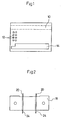
- the reference numerals 10 and 14 denote a magnetic stripe and an embossed region of the card respectively.
- the reference numerals 16, 18 and 40 denote a reading unit, a body and a plate spring respectively.
- an object of the invention to provide an IC reading pin module using an individual coil spring in which the above problems can be overcome and whose reading pins are biased by their associated compression coil springs and descend onto the IC contacts of an IC card to achieve the point contact between the pins and the IC contacts, thereby generating no scratch on the card, increasing the contact resistance, improving the durability of the module, letting the pins come into smooth contact with the IC contacts due to the coil springs even when the pins are physically deformed and achieving the stable contact between the pins and the IC contacts.
- the present invention provides an IC reading pin module using an individual coil spring comprising: a reading pin coming into contact with an IC contact of an IC card and reading out the information recorded in the card; a pin housing receiving the reading pin; a coil spring fitted over the top part of the reading pin and biasing the pin downward; and a plug fitted into the top of the housing and adapted to prevent sudden separation of both the reading pin and the coil spring from the housing.
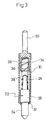
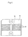
- Fig. 2 is a front view showing the IC reading pin modules set in a body according to the invention and Fig. 3 is a sectional view of the IC reading pin module using the individual coil spring according to the invention.
- each reading pin module has an IC reading pin 22 which is received in a pin housing 30 with a coil spring 36.
- the reading pin 22 generally comprises three parts, that is, a bottom rod part 24 called the first rod part, a cylindrical middle part 28 and a top rod part 26 called the second rod part.
- the first rod part 24 will come into direct contact with its associated IC contact of the IC card to read out the information recorded in the card.
- the cylindrical middle part 28 of the pin 22 slides in the housing 30.
- the coil spring 36 is fitted over the second rod part 26 and biases the pin 22 downward.
- the bottom edge of the pin housing 30 is bent inwardly to form a bottom shoulder 32 for stopping the bottom of the cylindrical middle part 28 of the pin 22.
- a plug 20 is inserted in the top part of the housing 30 to prevent sudden separation of both the pin 22 and the spring 36 from the housing 30.
- the bottom of the plug 20 is provided with a center hole 38 communicating with the inner space 38' defined in the cylindrical hollow body of the housing 30.
- the hole 38 receives the top portion of the spring 36 to stop the top of the spring 36.
- An annular groove 34 is formed on the outer surface of the plug 20. Due to the annular groove 34, the plug 20 is forcibly fitted into top part of the housing 30 provided with a corresponding annular groove.
- the reading pin modules having the spring-biased pins 22 are set in the body 18 of the reader such that the pins 22 correspond to their associated IC contacts 12 of the IC card of Fig. 1.
- the reading pins 22 of the module come into contact with their associated IC contacts 12 of the card.
- the pins 22 are lifted up in the housings 30 while compressing their coil springs 38 by the heights of their associated IC contacts 12.
- the IC reading pins of the module of this invention come into stable contact with the IC contacts of the IC card and minimize the contact resistance per unit contact area and thereby improving the contact efficiency and durability of the module.
Landscapes
- Engineering & Computer Science (AREA)
- Artificial Intelligence (AREA)
- Computer Vision & Pattern Recognition (AREA)
- Physics & Mathematics (AREA)
- General Physics & Mathematics (AREA)
- Theoretical Computer Science (AREA)
- Coupling Device And Connection With Printed Circuit (AREA)
Applications Claiming Priority (2)
| Application Number | Priority Date | Filing Date | Title |
|---|---|---|---|
| KR9428592 | 1994-10-31 | ||
| KR2019940028592U KR970006269Y1 (ko) | 1994-10-31 | 1994-10-31 | 인디비쥬얼(Individual)코일 스프링을 이용한 IC판독핀 모듈(Module) |
Publications (3)
| Publication Number | Publication Date |
|---|---|
| EP0709795A2 true EP0709795A2 (de) | 1996-05-01 |
| EP0709795A3 EP0709795A3 (de) | 1997-02-05 |
| EP0709795B1 EP0709795B1 (de) | 1998-11-04 |
Family
ID=19396882
Family Applications (1)
| Application Number | Title | Priority Date | Filing Date |
|---|---|---|---|
| EP95110420A Expired - Lifetime EP0709795B1 (de) | 1994-10-31 | 1995-07-04 | Chipkarten-Leserssteckstiftmodul mit einer individuellen Spiralfeder |
Country Status (3)
| Country | Link |
|---|---|
| EP (1) | EP0709795B1 (de) |
| KR (1) | KR970006269Y1 (de) |
| DE (1) | DE69505773T2 (de) |
Family Cites Families (2)
| Publication number | Priority date | Publication date | Assignee | Title |
|---|---|---|---|---|
| US4778982A (en) * | 1986-03-24 | 1988-10-18 | Data Card Corporation | System for entering integrated data on the face of an integrated chip card |
| DE9007300U1 (de) * | 1990-05-11 | 1991-04-11 | Richard Hirschmann GmbH & Co, 7300 Esslingen | Steckverbinder |
-
1994
- 1994-10-31 KR KR2019940028592U patent/KR970006269Y1/ko not_active Expired - Lifetime
-
1995
- 1995-07-04 DE DE69505773T patent/DE69505773T2/de not_active Expired - Fee Related
- 1995-07-04 EP EP95110420A patent/EP0709795B1/de not_active Expired - Lifetime
Non-Patent Citations (1)
| Title |
|---|
| None |
Also Published As
| Publication number | Publication date |
|---|---|
| EP0709795B1 (de) | 1998-11-04 |
| EP0709795A3 (de) | 1997-02-05 |
| DE69505773T2 (de) | 1999-05-20 |
| DE69505773D1 (de) | 1998-12-10 |
| KR970006269Y1 (ko) | 1997-06-24 |
| KR960015382U (ko) | 1996-05-17 |
Similar Documents
| Publication | Publication Date | Title |
|---|---|---|
| US8936199B2 (en) | UICC apparatus and related methods | |
| US6816386B2 (en) | Card connector for receiving information card with identifier therein | |
| US6592385B1 (en) | Card ejection mechanism for electronic card connector | |
| EP0595305B1 (de) | IC Kartenleser | |
| EP0701356A2 (de) | Errichtung zur Befestigung einer SIM Karte in einem mobilen Telefon | |
| US6764327B2 (en) | Electrical card connector with end position switch | |
| US20010014549A1 (en) | Blade switch assembly for a card reader | |
| WO1998027507A3 (en) | Landing type smart card reader | |
| KR19990067235A (ko) | 스마트 카드 및 스마트 카드 커넥터 | |
| US6692277B2 (en) | Electrical card connector with spring switch | |
| US6179638B1 (en) | Connector for use in a card reader | |
| US6721186B2 (en) | Electronic signal adapter module of flash memory card | |
| KR20000016871A (ko) | 오삽입방지기구부ic카드커넥터 | |
| EP0274684B1 (de) | Chipkartenleser | |
| JPH0850638A (ja) | マイクロサーキットカードの読取り装置 | |
| EP0929047A1 (de) | ID-Kartenleser | |
| CN100539310C (zh) | 特别用在sim卡或usim卡上的芯片卡接触装置 | |
| US6722906B2 (en) | Electrical connector | |
| WO2002021516A1 (fr) | Lecteur de carte magnetique | |
| EP0709795A2 (de) | Chipkarten-Leserssteckstiftmodul mit einer individueller Spiralfeder | |
| EP1000406B1 (de) | Verbinder zum verbinden einer ic karte der eine vorrichtung enthält zum automatischen auswerfen der karte | |
| EP0325458B1 (de) | Kartenleser | |
| US4794242A (en) | Chip card reader | |
| US6145747A (en) | Memory card and card connector and assembly thereof | |
| US6200166B1 (en) | Smart card interface arrangements |
Legal Events
| Date | Code | Title | Description |
|---|---|---|---|
| PUAI | Public reference made under article 153(3) epc to a published international application that has entered the european phase |
Free format text: ORIGINAL CODE: 0009012 |
|
| AK | Designated contracting states |
Kind code of ref document: A2 Designated state(s): DE FR GB IT |
|
| PUAL | Search report despatched |
Free format text: ORIGINAL CODE: 0009013 |
|
| 17P | Request for examination filed |
Effective date: 19961030 |
|
| AK | Designated contracting states |
Kind code of ref document: A3 Designated state(s): DE FR GB IT |
|
| 17Q | First examination report despatched |
Effective date: 19970530 |
|
| GRAG | Despatch of communication of intention to grant |
Free format text: ORIGINAL CODE: EPIDOS AGRA |
|
| GRAG | Despatch of communication of intention to grant |
Free format text: ORIGINAL CODE: EPIDOS AGRA |
|
| GRAH | Despatch of communication of intention to grant a patent |
Free format text: ORIGINAL CODE: EPIDOS IGRA |
|
| GRAH | Despatch of communication of intention to grant a patent |
Free format text: ORIGINAL CODE: EPIDOS IGRA |
|
| GRAA | (expected) grant |
Free format text: ORIGINAL CODE: 0009210 |
|
| AK | Designated contracting states |
Kind code of ref document: B1 Designated state(s): DE FR GB IT |
|
| REF | Corresponds to: |
Ref document number: 69505773 Country of ref document: DE Date of ref document: 19981210 |
|
| ET | Fr: translation filed | ||
| PLBE | No opposition filed within time limit |
Free format text: ORIGINAL CODE: 0009261 |
|
| STAA | Information on the status of an ep patent application or granted ep patent |
Free format text: STATUS: NO OPPOSITION FILED WITHIN TIME LIMIT |
|
| 26N | No opposition filed | ||
| REG | Reference to a national code |
Ref country code: GB Ref legal event code: IF02 |
|
| PGFP | Annual fee paid to national office [announced via postgrant information from national office to epo] |
Ref country code: FR Payment date: 20030819 Year of fee payment: 9 Ref country code: DE Payment date: 20030819 Year of fee payment: 9 |
|
| PGFP | Annual fee paid to national office [announced via postgrant information from national office to epo] |
Ref country code: GB Payment date: 20030821 Year of fee payment: 9 |
|
| PG25 | Lapsed in a contracting state [announced via postgrant information from national office to epo] |
Ref country code: GB Free format text: LAPSE BECAUSE OF NON-PAYMENT OF DUE FEES Effective date: 20040704 |
|
| PG25 | Lapsed in a contracting state [announced via postgrant information from national office to epo] |
Ref country code: DE Free format text: LAPSE BECAUSE OF NON-PAYMENT OF DUE FEES Effective date: 20050201 |
|
| GBPC | Gb: european patent ceased through non-payment of renewal fee |
Effective date: 20040704 |
|
| PG25 | Lapsed in a contracting state [announced via postgrant information from national office to epo] |
Ref country code: FR Free format text: LAPSE BECAUSE OF NON-PAYMENT OF DUE FEES Effective date: 20050331 |
|
| REG | Reference to a national code |
Ref country code: FR Ref legal event code: ST |
|
| PG25 | Lapsed in a contracting state [announced via postgrant information from national office to epo] |
Ref country code: IT Free format text: LAPSE BECAUSE OF NON-PAYMENT OF DUE FEES;WARNING: LAPSES OF ITALIAN PATENTS WITH EFFECTIVE DATE BEFORE 2007 MAY HAVE OCCURRED AT ANY TIME BEFORE 2007. THE CORRECT EFFECTIVE DATE MAY BE DIFFERENT FROM THE ONE RECORDED. Effective date: 20050704 |