EP0709072A1 - Device for positioning a hole in a bone - Google Patents
Device for positioning a hole in a bone Download PDFInfo
- Publication number
- EP0709072A1 EP0709072A1 EP95115227A EP95115227A EP0709072A1 EP 0709072 A1 EP0709072 A1 EP 0709072A1 EP 95115227 A EP95115227 A EP 95115227A EP 95115227 A EP95115227 A EP 95115227A EP 0709072 A1 EP0709072 A1 EP 0709072A1
- Authority
- EP
- European Patent Office
- Prior art keywords
- handle
- bore
- adjustment
- support
- bearing
- Prior art date
- Legal status (The legal status is an assumption and is not a legal conclusion. Google has not performed a legal analysis and makes no representation as to the accuracy of the status listed.)
- Granted
Links
Images


Classifications
-
- A—HUMAN NECESSITIES
- A61—MEDICAL OR VETERINARY SCIENCE; HYGIENE
- A61B—DIAGNOSIS; SURGERY; IDENTIFICATION
- A61B17/00—Surgical instruments, devices or methods, e.g. tourniquets
- A61B17/16—Bone cutting, breaking or removal means other than saws, e.g. Osteoclasts; Drills or chisels for bones; Trepans
- A61B17/17—Guides or aligning means for drills, mills, pins or wires
- A61B17/1739—Guides or aligning means for drills, mills, pins or wires specially adapted for particular parts of the body
- A61B17/1764—Guides or aligning means for drills, mills, pins or wires specially adapted for particular parts of the body for the knee
-
- A—HUMAN NECESSITIES
- A61—MEDICAL OR VETERINARY SCIENCE; HYGIENE
- A61F—FILTERS IMPLANTABLE INTO BLOOD VESSELS; PROSTHESES; DEVICES PROVIDING PATENCY TO, OR PREVENTING COLLAPSING OF, TUBULAR STRUCTURES OF THE BODY, e.g. STENTS; ORTHOPAEDIC, NURSING OR CONTRACEPTIVE DEVICES; FOMENTATION; TREATMENT OR PROTECTION OF EYES OR EARS; BANDAGES, DRESSINGS OR ABSORBENT PADS; FIRST-AID KITS
- A61F2/00—Filters implantable into blood vessels; Prostheses, i.e. artificial substitutes or replacements for parts of the body; Appliances for connecting them with the body; Devices providing patency to, or preventing collapsing of, tubular structures of the body, e.g. stents
- A61F2/02—Prostheses implantable into the body
- A61F2/30—Joints
- A61F2/38—Joints for elbows or knees
- A61F2/3836—Special connection between upper and lower leg, e.g. constrained
- A61F2/384—Special connection between upper and lower leg, e.g. constrained hinged, i.e. with transverse axle restricting the movement
- A61F2/385—Special connection between upper and lower leg, e.g. constrained hinged, i.e. with transverse axle restricting the movement also provided with condylar bearing surfaces
-
- A—HUMAN NECESSITIES
- A61—MEDICAL OR VETERINARY SCIENCE; HYGIENE
- A61B—DIAGNOSIS; SURGERY; IDENTIFICATION
- A61B17/00—Surgical instruments, devices or methods, e.g. tourniquets
- A61B17/14—Surgical saws ; Accessories therefor
- A61B17/15—Guides therefor
- A61B17/154—Guides therefor for preparing bone for knee prosthesis
- A61B17/155—Cutting femur
-
- A—HUMAN NECESSITIES
- A61—MEDICAL OR VETERINARY SCIENCE; HYGIENE
- A61F—FILTERS IMPLANTABLE INTO BLOOD VESSELS; PROSTHESES; DEVICES PROVIDING PATENCY TO, OR PREVENTING COLLAPSING OF, TUBULAR STRUCTURES OF THE BODY, e.g. STENTS; ORTHOPAEDIC, NURSING OR CONTRACEPTIVE DEVICES; FOMENTATION; TREATMENT OR PROTECTION OF EYES OR EARS; BANDAGES, DRESSINGS OR ABSORBENT PADS; FIRST-AID KITS
- A61F2/00—Filters implantable into blood vessels; Prostheses, i.e. artificial substitutes or replacements for parts of the body; Appliances for connecting them with the body; Devices providing patency to, or preventing collapsing of, tubular structures of the body, e.g. stents
- A61F2/02—Prostheses implantable into the body
- A61F2/30—Joints
- A61F2/38—Joints for elbows or knees
- A61F2/3836—Special connection between upper and lower leg, e.g. constrained
- A61F2/384—Special connection between upper and lower leg, e.g. constrained hinged, i.e. with transverse axle restricting the movement
- A61F2/3845—Special connection between upper and lower leg, e.g. constrained hinged, i.e. with transverse axle restricting the movement allowing only for single rotation
Definitions
- the invention relates to a device for placing a bore in a bone, in particular when implanting joint-forming hinge endoprostheses in which the pivot axis of the joint lies in a bearing journal which is subsequently inserted through a bore in bone.
- Such hinge endoprostheses are described using the example of a knee joint endoprosthesis in ePa 91 120 536.7, from which the present application emerged as a divisional application and which should be used for any clarification.
- the described knee joint endoprosthesis has a femur part and a tibia part which, after implantation, can be pivoted from an extended position into an angled position in a flexion plane about the pivot axis running in the longitudinal direction of the bearing journal, and each have a shaft which can be inserted into the femur or into the tibia bone exhibit.
- a housing which receives the two ends of the journal in the receiving openings of two lateral bearing shells and is inserted into the lower end of the femur so that it is surrounded by bones in the longitudinal direction of the journal on both sides of the bearing shells .
- the housing has a downwardly open recess into which a web forming the upper end of the tibia part engages with a through hole for the bearing journal.
- the stems are inserted into the femur or tibia bone and then the femur is drilled in the extension of the receiving openings of the bearing shells on one side of the housing, in order to pass the bearing journal from the outside through the hole in the bone, the first bearing shell, to push the through hole in the bridge and then into the second bearing shell and thus connect the femur part and the tibia part with each other.
- the bearing pin has been subsequently fastened in the web of the tibia part, the piece of bone removed with a pot cutter is reinserted into the bore.
- the object of the present invention is therefore to create a device of the type mentioned at the outset, with the aid of which the necessary drilling can be made in the bone with high precision.
- This object is achieved according to the invention in that an adjustment which can be aligned centrally with respect to the bore to be introduced is provided, which is arranged at a distance from a drill sleeve which guides a bore producing the bore.
- the design of the device according to the invention enables the operating surgeon to drill the hole in the bone within a short time and with high precision.
- the surgeon is relieved of manual alignments and any necessary directional corrections.
- the adjustment can be made in a bearing shell receiving the bearing journal to be inserted. In this way, an exact central alignment of the bore in relation to the bearing journal to be inserted is achieved.
- a support element which is displaceable along a stem of the device is provided.
- this support element can be introduced into the interior of the tibia part and fixed there with respect to the stem and reliably prevents the device from tilting.
- the support element fills a free space which extends between the bearing shells with a support. Due to the interaction of the adjustment and the support element, the combination of device and femur part has no freedom of movement in the lateral tilt during the drilling process, but only in the flexion plane. Relative movements of the parts relative to one another transversely to the bending plane can thus be excluded.
- a bone plug is removed from the bone surrounding the femoral part in the extension of the pivot axis. Through the hole created in the bone, it is inserted into the knee joint for a while to connect the femoral part to the tibia part. After this shaft has been assembled, the bone plug is put back into the drilled hole of the bone, where it creates a natural connection with it and stiffens it.
- a knee joint endoprosthesis essentially consists of a tibia part (1) and a femur part (2).
- the tibia part (1) has a tibia shaft (3)
- the femoral part (2) has a femoral shaft (4).
- the two shafts (3, 4) point in opposite directions and serve to fasten the parts (1, 2) in a bone adjacent to them.
- a housing (6) In the area of the extension of the femur part (2) facing the tibia part (1), a housing (6) is arranged which guides a bearing pin (5).
- This bearing pin (5) is fastened in the tibia part (1) and rotatably mounted in the femoral part (2).
- the two parts (1, 2) When rotating the bearing journal (5), the two parts (1, 2) perform pivoting movements in a bending plane (96) against each other.
- flexion movements lead from an extended position in which a shaft plane (97, 123) extending perpendicular to the flexion plane (96) extends through each of the two shafts (3, 4) into a pivoted position (110) in which one extends through the femoral shaft (4) extending femur longitudinal axis (7) with a through the tibial shaft (3) extending tibial longitudinal axis (16) includes a flexion angle (111) between them.
- This flexion angle (111) encloses a rear part (112) of the femur part (2) and a rear part (113) of the tibia part (1).
- the housing has recesses (10, 11) in the area of its lateral boundaries (8, 9) which extend essentially plane-parallel to the flexion plane (96). These recesses (10, 11) are aligned essentially centrally to a pivot axis (12) which extends through the bearing journal (5) and extends essentially transversely to the bending plane (96).
- a vertical plane (78) extends through the pivot axis (12), which is plane-parallel at a horizontal distance (13) to the shaft plane (123) extending through the femoral shaft (4) and at a horizontal distance (121) from the tibia shaft ( 3) extending shaft plane (97).
- the pivot axis (12) extends through a horizontal plane (79), which has a vertical distance (15) to a horizontal displacement plane (114) in the direction of the tibia part (1).
- This horizontal displacement plane (114) extends tangentially to a line (115) which extends perpendicular to the flexion plane (96) through a support surface (117) formed on the tibia part (1) opposite the femur part (2).
- This support surface (117) is designed in the direction of the femur part (2) opposite a sliding surface (14) which is suitable for sliding movements on the support surface (117) when the tibia part (1) pivots with respect to the pivot axis (12) of the femoral part (2).
- the tibia shaft (3) runs in the direction of a longitudinal axis of the tibia (16) and the femoral shaft (4) in the direction of a longitudinal axis of the femur (7).
- the femoral shaft (4) has an oblique position in relation to the tibia shaft (3) in a front view running transversely to the shaft plane (123). This inclination corresponds to an average valgus angle.
- the recesses (10, 11) serve to receive bearing shells (27, 28) in which the bearing journal (5) is rotatably mounted.
- These bearing shells (27, 28) each have a collar (23, 24) with which they protrude into the recesses (10, 11).
- To this covenant (23, 24) are followed by contact surfaces (21, 22) with which the bearing shells (27, 28) protrude into a housing interior (20) enclosed by the housing (6).
- These support surfaces (21, 22) lie with their outer surfaces (18, 19) facing away from the housing interior (20) on the lateral boundaries (8, 9) of the housing (6). In this way, the housing interior (20) is delimited on both sides by inner walls (98, 99) which are formed by the bearing shells (27, 28).
- bearing shells (27, 28) consist of polyethylene and therefore represent an ideal sliding partner for a web (33) with which the tibia part (1) protrudes into the housing interior (20).
- the dimensions of the web (33) are chosen so that it is guided with its side walls (93, 94) on the inner walls (98, 99).
- This blind hole (29) is delimited by a bottom (30) closing it, which guides the bearing journal (5) in the longitudinal direction of the pivot axis (12).
- Both the through hole (31) and the blind hole (29) have an inner diameter (32) which corresponds to an outer diameter of the journal (5), so that it is guided both in the through hole (31) and in the blind hole (29).
- the lateral boundaries (8, 9) delimiting the housing (6) have wings (25, 26) on their outer surfaces facing away from the housing interior (20), which wings extend from the housing (6) in a direction facing away from the interior (20). These wings (25, 26) extend in an arc on a lower edge (82) in directions pointing away from each other. This lower edge (82) faces the tibia part (1).
- the sliding surface (14) is located on a lower surface of the wings (25, 26) facing the tibia part (1).
- the wings (25, 26) have a relatively large width parallel to the direction of the pivot axis (12), so that they span a wide sliding surface (14) with which they are guided on a bearing surface (38) which is on the tibia part (1st ) is arranged.
- This bearing surface (38) represents a curved bearing surface (117), the curvature of which is simulated essentially that of the wings (25, 26).
- the width of each of the two wings (25, 26) corresponds approximately to half the width that the housing (6) has.
- the sliding surfaces (14) of the two wings (25, 26) each have a slight inclination that is convex in the direction of the tibia part (1) and extends from the housing (6) in the direction of the outer edges (80, 81).
- outer edges (80, 81) limit the wings (25, 26) on their side opposite the housing (6).
- These outer edges (80, 81) essentially congruent with outer edges (84, 85) of a support plate (35) which delimits the tibia part (1) relative to the femur part (2).
- This support plate (35) spans a support surface (117) extending transversely to the direction of the shaft plane (97).
- the wings (25, 26) extend over an arc of approximately 180 ° that is approximately concentric with the pivot axis (12) along the lower edge (82) of the femoral part (2).
- Each wing (25, 26) has an end (83) pointing in the direction of the rear part (112) of the femur part, which is formed by a cutting line () formed by the horizontal plane (79) with the lower edge (82) of the housing (6) 86) runs in a circular arc concentrically to the central axis (12) and, when the knee joint endoprosthesis is stretched, has a rear end (83) just above the horizontal plane (79). This rear end (83) is adjacent to the contact surface (117) when the femoral part (2) is pivoted relative to the tibia part (1).
- Each wing (25, 26) extends along an arc (87) from the rear end (83) to a front end (88) opposite this, which in a front end face (89) opposite the rear part (112) of the femur part (2) ) of the housing (6).
- the front end (88) lies approximately the same distance in the direction of the tibia part (1) below the horizontal plane (79) as the rear end (83) lies above this horizontal plane (79).
- the arc (87) has different radii of curvature from the rear end (83) to the front end (88). It is curved to a lesser extent in the area of its rear end (83) and in the area of its front end (88) than in its central area (90).
- the front ends (88) of the two wings (25, 26) are connected to one another via a short short arch (91) which is curved away from the tibia part (1) and is formed in a front end wall (92) delimiting the housing (6).
- the web (33) has a recess (34) which is designed as a bore which runs essentially centrally to the pivot axis (12). This serves to receive the shaft (5).
- the web (33) rises on the support plate (35), to the horizontal surface of which the side walls (93, 94) run vertically. These side walls (93, 94) are at approximately the same distance (95) from the flexion plane (96) which extends centrally through the tibia part (1).
- the side walls (93, 94) thus also run plane-parallel to the inner walls (98, 99) of the housing (6) on which they are guided.
- the housing interior (20) has a substantially rectangular cross section transverse to the flexion plane (96).
- the housing interior (20) is delimited in the direction of the front end (88) by the end surface (89) which runs essentially plane-parallel to the shaft plane (123), while it is open in the direction of the rear end (83).
- the web (33) rises centrally on the support plate (35). It is designed as an eyelet, the upper boundary (100) facing the femur part (2) is designed as a rounding that is concentric with the recess (34).
- the web (33) extends in the direction of the femur part (2) through a bearing shell (37) which is arranged on the support plate (35). This support plate (35) is supported with the aid of ribs (36) in relation to the tibia shaft (3).
- the bearing shell (37) engages around the web (33) in a U-shape and extends along the side walls (93, 94) with two webs (101, 102) which, in a front part (103) facing the front end face (89), of the Support plate (35) are interconnected by a yoke (104).
- An opening (105) extends between the two webs (101, 102) up to a rear part (106) of the support plate opposite the front part (103) (35). On this rear part (106) of the support plate, the web (33) rises through the opening (105).
- the bearing surface (38) which faces the sliding surface (14) is formed on the bearing shell (37).
- the bearing surface (38) runs on a surface of the webs (101, 102) facing the femur part (2) from the front part (103) in the direction of the rear part (106) into which they open.
- the bearing surface (38) has a front part (107) facing the yoke (104), which is opposite the front end (88) of the wings (25, 26). Compared to a flat part (108) of the bearing surface (38) which opens into the rear part of the bearing shell (37), the front part (107) is raised in the direction of the femur part (2).
- the flat part (108) of the bearing surface (38) extends within the bearing surface (117).
- the bearing surface (38) has a curvature (116) in the longitudinal direction from its flat part (108) to its front part (107), which has a relatively steep rise in its third facing the front part (107).
- the bearing surface (38) has a curvature in its transverse direction running transversely to the longitudinal direction, which is adapted to the curvature of the sliding surface (14).
- the wings (25, 26) are guided on this curvature running in the transverse direction when bending movements are carried out.
- This curvature extending in the transverse direction stabilizes the knee joint in the extended position in that the tibia part (2) in the front part (103) of the support plate (35) guides the lower edge (82) of the housing (6) in a form-fitting manner.
- the bearing journal (5) is fastened in the recess (34) with the aid of a grub screw (46).
- This extends through a bore (41) which extends transversely to the pivot axis (12) through the web (33) in Direction towards the recess (34).
- the bore (41) corresponds to a bore (44) provided in the bearing journal (5), into which the grub screw (46) protrudes when it is screwed into the bore (41).
- the bearing journal (5) is fixed within the recess (34).
- the grub screw (45) is screwed into the bore (41) until its end facing away from the bearing journal (5) lies below a surface of the web (33) within the bore (41).
- the grub screw (45) is fixed with bone cement and in this way it is avoided that it turns out of the bore (41) during use of the prosthesis and with its end protruding from the bore (41) the housing ( 6) destroyed and with its other end loses the connection with the bearing journal (5).
- the bearing pin (5) protrudes with its two ends (118, 119) on both sides out of the recess (34), so that these ends (118, 119) in the receiving openings (29, 31) of the bearing shells (27, 28) can be stored.
- a bore (42) can be arranged in the bearing journal (5), which extends in the direction of the pivot axis (12) and is provided with an internal thread (43).
- This hole (42) is used to mount the bearing pin (5) when it is fitted through the through hole (31) into the blind hole (29) and then aligned so that the grub screw (46) through the hole (41) is screwed into the bore (44) provided with an internal thread (45).
- a device for placing a hole in a bone essentially has an adjustment (50) and a drill sleeve (51) which are arranged at a distance (52) from one another.
- the adjustment (50) is essentially cylindrical and is adapted to the inside diameter of the bearing shells (27, 28). However, it is also possible to use working bearing shells (53, 54) instead of the bearing shells (27, 28) during the introduction of the bore into the bone.
- the adjustment (50) and the drill sleeve (51) are arranged centrally to a drill axis (55). In the area of its boundary facing the adjustment (50), the drill sleeve (51) opens into a spacer (56).
- the spacer (56) is essentially U-shaped and carries the drill sleeve (51) in the region of its one side leg (57).
- the adjustment (50) is arranged in the area of the boundary of the other side leg (58) facing the drill sleeve (51).
- the side legs (57, 58) are connected to one another by a base leg (59).
- the base leg (59) opens into a stem (60) which extends essentially parallel to the direction of the side legs (57, 58).
- the handle (60) opens into a handle (61) which extends essentially transversely to a longitudinal axis (62) of the handle.
- a stop ring (63) is slidably mounted on the handle (60) in the area between the base leg (59) and the handle (61) along the longitudinal axis of the handle (62). With its end face facing away from the handle (61), a stop element (64 ) is adjacent and this acts upon displacement along the longitudinal axis (62).
- This support element (64) is arranged to be displaceable along the longitudinal axis of the stem (62) and has a guide sleeve (65) which partially surrounds the stem (60) and a support (66).
- the guide sleeve (65) can be fixed in position relative to the handle (60) with the aid of a locking device (67), which is designed, for example, as a screw (68).
- the guide sleeve (65) is connected to the support (66) via a support arm (69).
- the support (66) has a design adapted to the housing interior (20). In the direction of the pivot axis (12), the support (66) has dimensions which, together with the dimensions of the side leg (58), correspond to the internal dimensions of the housing interior (20) in the direction of the pivot axis (12).
- the drill sleeve (51) is provided for receiving a pot cutter (70).
- the pot mill (70) is connected to a drill shaft (72) so that it can be replaced by a lock (71).
- the tibia and femur bones are first prepared to accommodate the shafts (3, 4). After the insertion of the shafts (3, 4) and their fixation relative to the bone receiving them, the side leg becomes (58) inserted into the housing interior (20) and the adjustment (50) positioned in the area of the bearing shell (30) or in the area of one of the working bearing shells (53, 54). The support element (64) is then displaced in the direction of the housing interior (20) and inserted with the support (66) into the housing interior (20).
- the support element (64) does not slide into the housing (6) without difficulty or is not well aligned in the housing (6), its position can be corrected by careful blows with the stop ring (63) until the Drill sleeve (51) is aligned precisely with the borehole to be exposed.
- the support element (64) has been fixed in relation to the handle (60) by tightening the locking device (67)
- the device is held without play in the area of the housing (6).
- the drilling axis (55) now coincides with the pivot axis (12).
- a bone plug can be removed from the femur bone with the aid of the pot mill (70), which is guided through the drill sleeve (51) in the direction of the femur bone.
- the bearing pin (5) After inserting the bearing pin (5), which is screwed for this purpose with its internal thread (43) onto an external thread (73) of an assembly tool (74), the bearing pin (5) is removed with the help of the grub screw (46), which is through the Bore (41) is fed to the internal thread (45), locked in relation to the femur part (2).
- the bone plug removed with the aid of the pot mill (70) is reinserted into the recess made in the femur.
- the tibia part (1) and the femoral part (2) are positioned relative to one another such that the recesses (10, 11) of the femoral part and the recess (34) of the tibia part are centered on a common pivot axis (12 ) are aligned.
- An easy to assemble and then dismantle test axis is then passed through the recesses (10, 11, 34), with the help of which it is tested whether all the parts are correctly assembled and can be moved well against one another. If necessary, corrections can be made.
- the test axis is removed and the bearing pin (5) is fitted, which ensures that the joint parts work together in the desired way.
- the bearing pin (5) is mounted in such a way that the grub screw (46) is tightened with a screwdriver (75).
- the one during implantation Lever forces to be applied manually to the endoprosthesis can be generated with the aid of a lever tool (76).
Abstract
Description
Die Erfindung betrifft eine Vorrichtung zur Plazierung einer Bohrung in einem Knochen, insbesondere bei einer Implantation von gelenkbildenden Scharnierendoprothesen bei denen die Schwenkachse des Gelenks in einem Lagerzapfen liegt, welcher nachträglich durch eine Bohrung in Knochen eingesetzt wird.The invention relates to a device for placing a bore in a bone, in particular when implanting joint-forming hinge endoprostheses in which the pivot axis of the joint lies in a bearing journal which is subsequently inserted through a bore in bone.
Derartige Scharnierendoprothesen sind am Beispiel einer Kniegelenkendoprothese in der ePa 91 120 536.7 beschrieben, aus der die vorliegende Anmeldung als Teilanmeldung hervorgegangen ist, und die für eine eventuelle Klarstellung herangezogen werden sollte. Die beschriebene Kniegelenkendoprothese weist einen Femurteil und einen Tibiateil auf, die nach der Implantation um die in Längsrichtung des Lagerzapfens verlaufende Schwenkachse in einer Beugeebene aus einer gestreckten Stellung in eine abgewinkelte Stellung verschwenkbar sind und die jeweils einen in den Femur bzw. in den Tibiaknochen einsetzbaren Schaft aufweisen. An den Schaft des Femurteils schließt sich dort ein Gehäuse an, welches die beiden Stirnenden des Lagerzapfens in Aufnahmeöffnungen zweier seitlicher Lagerschalen aufnimmt und so in das untere Ende des Femurs eingelassen ist, daß es in Längsrichtung des Lagerzapfens auf beiden Seiten der Lagerschalen von Knochen umgeben ist. Das Gehäuse weist eine nach unten offene Ausnehmung auf, in die ein das obere Ende des Tibiateils bildender Steg mit einer Durchgangsbohrung für den Lagerzapfen eingreift. Nach einer Vorbereitung des Femurs und des Tibiaknochens werden die Schäfte in den Femur bzw. Tibiaknochen eingesetzt und dann der Femur in Verlängerung der Aufnahmeöffnungen der Lagerschalen auf einer Seite des Gehäuses durchbohrt, um den Lagerzapfen von außen durch die Bohrung im Knochen, die erste Lagerschale, die Durchgangsbohrung im Steg und dann in die zweite Lagerschale zu schieben und damit den Femurteil und den Tibiateil miteinander zu verbinden. Nach einer anschließenden Befestigung des Lagerzapfens im Steg des Tibiateils wird das mit einem Topffräser entfernte Knochenstück wieder in die Bohrung eingesetzt.Such hinge endoprostheses are described using the example of a knee joint endoprosthesis in ePa 91 120 536.7, from which the present application emerged as a divisional application and which should be used for any clarification. The described knee joint endoprosthesis has a femur part and a tibia part which, after implantation, can be pivoted from an extended position into an angled position in a flexion plane about the pivot axis running in the longitudinal direction of the bearing journal, and each have a shaft which can be inserted into the femur or into the tibia bone exhibit. At the shaft of the femoral part there is a housing, which receives the two ends of the journal in the receiving openings of two lateral bearing shells and is inserted into the lower end of the femur so that it is surrounded by bones in the longitudinal direction of the journal on both sides of the bearing shells . The housing has a downwardly open recess into which a web forming the upper end of the tibia part engages with a through hole for the bearing journal. After preparation of the femur and the tibia bone, the stems are inserted into the femur or tibia bone and then the femur is drilled in the extension of the receiving openings of the bearing shells on one side of the housing, in order to pass the bearing journal from the outside through the hole in the bone, the first bearing shell, to push the through hole in the bridge and then into the second bearing shell and thus connect the femur part and the tibia part with each other. After the bearing pin has been subsequently fastened in the web of the tibia part, the piece of bone removed with a pot cutter is reinserted into the bore.
Da die Bohrung im Knochen genau mit der vorgesehenen Schwenkachse fluchten muß, ist es erforderlich, die Bohrung mit hoher Präzision einzubringen, wodurch auch eine zusätzliche Schwächung der Knochensubstanz vermieden werden kann.Since the hole in the bone must be exactly aligned with the intended swivel axis, it is necessary to drill the hole with high precision, as a result of which an additional weakening of the bone substance can also be avoided.
Aufgabe der vorliegenden Erfindung ist es daher, eine Vorrichtung der eingangs genannten Art zu schaffen, mit deren Hilfe die erforderliche Bohrung mit hoher Präzision in den Knochen eingebracht werden kann.The object of the present invention is therefore to create a device of the type mentioned at the outset, with the aid of which the necessary drilling can be made in the bone with high precision.
Diese Aufgabe wird erfindungsgemäß dadurch gelöst, daß eine zentrisch zur einzubringenden Bohrung ausrichtbare Justierung vorgesehen ist, die mit einem Abstand zu einer einen die Bohrung herstellenden Bohrer führenden Bohrhülse angeordnet ist.This object is achieved according to the invention in that an adjustment which can be aligned centrally with respect to the bore to be introduced is provided, which is arranged at a distance from a drill sleeve which guides a bore producing the bore.
Die erfindungsgemäße Ausbildung der Vorrichtung ermöglicht es dem operierenden Chirurgen innerhalb kurzer Zeit und mit hoher Präzision die Bohrung in den Knochen einzubringen. Durch die Benutzung der Vorrichtung wird der Chirurg von manuellen Ausrichtungen und gegebenenfalls erforderlichen Richtungskorrekturen entlastet. Die Justierung kann in eine den einzubringenden Lagerzapfen aufnehmende Lagerschale eingebracht werden. Hierdurch wird eine exakte zentrische Ausrichtung der Bohrung in Relation zum einzubringenden Lagerzapfen erreicht.The design of the device according to the invention enables the operating surgeon to drill the hole in the bone within a short time and with high precision. By using the device, the surgeon is relieved of manual alignments and any necessary directional corrections. The adjustment can be made in a bearing shell receiving the bearing journal to be inserted. In this way, an exact central alignment of the bore in relation to the bearing journal to be inserted is achieved.
Gemäß einer bevorzugten Ausführungsform der Erfindung ist ein entlang eines Stieles der Vorrichtung verschiebliches Abstützelement vorgesehen. Dieses Abstützelement kann nach einem Einbringen der Justierung in den Bereich der Lagerschale in den Gehäuseinnenraum des Tibiateils eingebracht und dort bezüglich des Stieles fixiert werden und verhindert zuverlässig ein Verkanten der Vorrichtung. Das Abstützelement füllt während des Bohrvorganges mit einer Stütze einen sich zwischen den Lagerschalen erstreckenden freien Zwischenraum aus. Durch das Zusammenwirken der Justierung und des Abstützelenentes besitzt die Kombination aus Vorrichtung und Femurteil während des Bohrvorganges keine Bewegungsfreiheit in der seitlichen Verkantung, sondern nur in der Beugeebene. Relativbewegungen der Teile zueinander quer zur Beugeebene können somit ausgeschlossen werden. Auch bei während des Bohrvorganges einwirkenden Kräften ist somit für eine genaue Plazierung und exakte Ausführung der Bohrung gesorgt, zu deren Herstellung ein Hohlbohrer verwendet wird. Mit seiner Hilfe wird in der Verlängerung der Schwenkachse ein Knochenpfropf aus dem den Femurteil umgebenden Knochen entfernt. Durch das dadurch im Knochen entstehende Loch wird eine Weile zur Verbindung des Femurteils mit dem Tibiateil in das Kniegelenk eingeführt. Nachdem diese Welle montiert worden ist, wird der Knochenpfropf wieder in das ausgebohrte Loch des Knochens eingesetzt, wo er eine natürliche Verbindung mit diesem herstellt und ihn versteift.According to a preferred embodiment of the invention, a support element which is displaceable along a stem of the device is provided. After the adjustment has been introduced into the region of the bearing shell, this support element can be introduced into the interior of the tibia part and fixed there with respect to the stem and reliably prevents the device from tilting. During the drilling process, the support element fills a free space which extends between the bearing shells with a support. Due to the interaction of the adjustment and the support element, the combination of device and femur part has no freedom of movement in the lateral tilt during the drilling process, but only in the flexion plane. Relative movements of the parts relative to one another transversely to the bending plane can thus be excluded. Even with the forces acting during the drilling process, this ensures precise placement and execution the bore, for the manufacture of which a hollow drill is used. With its help, a bone plug is removed from the bone surrounding the femoral part in the extension of the pivot axis. Through the hole created in the bone, it is inserted into the knee joint for a while to connect the femoral part to the tibia part. After this shaft has been assembled, the bone plug is put back into the drilled hole of the bone, where it creates a natural connection with it and stiffens it.
Weitere Einzelheiten und Merkmale der Erfindung ergeben sich aus der nachfolgenden ausführlichen Beschreibung und den beigefügten Zeichnungen, in denen bevorzugte Ausführungsformen der Erfindung beispielsweise veranschaulicht sind.Further details and features of the invention will become apparent from the following detailed description and the accompanying drawings, in which preferred embodiments of the invention are illustrated, for example.
In den Zeichnungen zeigen:
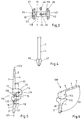
- Fig. 1: Einen Längsschnitt durch eine Endoprothese mit vom Tibiateil abgenommenen Femurteil gemäß Schnittlinie I-I in Fig. 2,
- Fig. 2: eine Seitenansicht der Endoprothese gemäß Fig.1,
- Fig. 3: einen Längsschnitt durch zwei zur Aufnahme des Lagerzapfens vorgesehene Lagerschalen und eine Ansicht eines Lagerzapfens mit einer Zentrierschraube,
- Fig. 4: eine teilweise Darstellung eines Prothesenschaftes mit Zentrierstern,
- Fig. 5: eine skizzenhafte Darstellung der gestreckten Endoprothese mit Achsenlagen in Relation zu den Schäften und zur Abrollfläche,
- Fig. 6: eine skizzenhafte Darstellung der verschwenkten Endoprothese,
- Fig. 7: eine schematische Darstellung der Vorbereitung des Femurteils zur Aufnahme der Vorrichtung zur Plazierung der Bohrung,
- Fig. 8: eine schematische Darstellung der relativen Anordnung der Vorrichtung zum Femurteil vor dem Einsetzen der Vorrichtung,
- Fig. 9: eine schematische Darstellung einer in das Femurteil eingesetzten Vorrichtung,
- Fig.10: eine schematische Darstellung der relativen Anordnung eines Bohrers zur Vorrichtung vor Beginn des Bohrvorganges,
- Fig.11: eine Seitenansicht eines Werkzeuges zur Einbringung von Hebelkräften,
- Fig.12: eine Seitenansicht eines Werkzeuges zur Plazierung des Lagerzapfens,
- Fig.13: eine Seitenansicht eines Werkzeuges zum Einsetzen von Sicherungsschrauben,
- Fig.14: eine Seitenansicht eines von der Bohrhülse aufnehmbaren Bohrers,
- Fig.15: eine Seitenansicht einer Vorrichtung zur Plazierung einer Bohrung.
- 1: a longitudinal section through an endoprosthesis with the femoral part removed from the tibia part according to section line II in FIG. 2,
- 2: a side view of the endoprosthesis according to Figure 1,
- 3: a longitudinal section through two bearing shells provided for receiving the bearing journal and a view of a bearing journal with a centering screw,
- 4: a partial representation of a prosthesis socket with centering star,
- 5: a sketchy representation of the stretched endoprosthesis with axial positions in relation to the shafts and the rolling surface,
- 6: a sketchy representation of the pivoted endoprosthesis,
- 7: a schematic representation of the preparation of the femoral part for receiving the device for placing the bore,
- 8: a schematic representation of the relative arrangement of the device for the femoral part before the device is inserted,
- 9: a schematic representation of a device inserted into the femoral part,
- 10: a schematic representation of the relative arrangement of a drill to the device before the start of the drilling process,
- 11: a side view of a tool for introducing lever forces,
- 12: a side view of a tool for placing the bearing journal,
- Fig. 13: a side view of a tool for inserting locking screws,
- 14: a side view of a drill that can be received by the drill sleeve,
- 15: a side view of a device for placing a bore.
Eine Kniegelenkendoprothese besteht im wesentlichen aus einem Tibiateil (1) und einem Femurteil (2). Das Tibiateil (1) weist einen Tibiaschaft (3), das Femurteil (2) einen Femurschaft (4) auf. Die beiden Schäfte (3, 4) weisen in einander abgewandte Richtungen und dienen zur Befestigung der Teile (1, 2) in einem ihnen jeweils benachbarten Knochen.A knee joint endoprosthesis essentially consists of a tibia part (1) and a femur part (2). The tibia part (1) has a tibia shaft (3), the femoral part (2) has a femoral shaft (4). The two shafts (3, 4) point in opposite directions and serve to fasten the parts (1, 2) in a bone adjacent to them.
Im Bereich der dem Tibiateil (1) zugewandten Ausdehnung des Femurteils (2) ist ein Gehäuse (6) angeordnet, das einen Lagerzapfen (5) führt. Dieser Lagerzapfen (5) ist im Tibiateil (1) befestigt und im Femurteil (2) drehbar gelagert. Bei der Ausführung von Drehbewegungen des Lagerzapfens (5) führen die beiden Teile (1, 2) Schwenkbewegungen in einer Beugeebene (96) gegeneinander aus. Diese Beugebewegungen führen von einer gestreckten Stellung, in der sich durch jeden der beiden Schäfte (3, 4) eine senkrecht zur Beugeebene (96) verlaufende Schaftebene (97, 123) erstreckt, in eine verschwenkte Stellung (110), in der eine sich durch den Femurschaft (4) erstreckende Femurlängsachse (7) mit einer sich durch den Tibiaschaft (3) erstreckenden Tibialängsachse (16) einen Beugewinkel (111) zwischen sich einschließt. Dieser Beugewinkel (111) umschließt einen hinteren Teil (112) des Femurteils (2) und einen hinteren Teil (113) des Tibiateils (1).In the area of the extension of the femur part (2) facing the tibia part (1), a housing (6) is arranged which guides a bearing pin (5). This bearing pin (5) is fastened in the tibia part (1) and rotatably mounted in the femoral part (2). When rotating the bearing journal (5), the two parts (1, 2) perform pivoting movements in a bending plane (96) against each other. These flexion movements lead from an extended position in which a shaft plane (97, 123) extending perpendicular to the flexion plane (96) extends through each of the two shafts (3, 4) into a pivoted position (110) in which one extends through the femoral shaft (4) extending femur longitudinal axis (7) with a through the tibial shaft (3) extending tibial longitudinal axis (16) includes a flexion angle (111) between them. This flexion angle (111) encloses a rear part (112) of the femur part (2) and a rear part (113) of the tibia part (1).
Im Bereich seiner sich im wesentlichen planparallel zur Beugeebene (96) erstreckenden seitlichen Begrenzungen (8, 9) weist das Gehäuse Ausnehmungen (10, 11) auf. Diese Ausnehmungen (10, 11) sind im wesentlichen zentrisch zu einer sich durch den Lagerzapfen (5) erstreckenden Schwenkachse (12) ausgerichtet, der sich in wesentlichen quer zur Beugeebene (96) erstreckt. Durch die Schwenkachse (12) erstreckt sich eine Vertikalebene (78), die planparallel in einem Horizontalabstand (13) zu der sich durch den Femurschaft (4) erstreckenden Schaftebene (123) und in einem Horizontalabstand (121) zu der sich durch den Tibiaschaft (3) erstreckenden Schaftebene (97) verläuft. Darüber hinaus erstreckt sich die Schwenkachse (12) durch eine Horizontalebene (79), die in Richtung auf den Tibiateil (1) einen Vertikalabstand (15) zu einer horizontalen Verschiebeebene (114) besitzt. Diese horizontale Verschiebeebene (114) verläuft tangential an eine Linie (115), die sich senkrecht zur Beugeebene (96) durch eine dem Femurteil (2) gegenüber auf dem Tibiateil (1) ausgebildete Auflagefläche (117) erstreckt. Diese Auflagefläche (117) ist in Richtung auf den Femurteil (2) gegenüber einer Gleitfläche (14) ausgebildet, die geeignet ist, auf der Auflagefläche (117) gleitend Bewegungen auszuführen, wenn das Tibiateil (1) um die Schwenkachse (12) Schwenkbewegungen bezüglich des Femurteils (2) ausführt.The housing has recesses (10, 11) in the area of its lateral boundaries (8, 9) which extend essentially plane-parallel to the flexion plane (96). These recesses (10, 11) are aligned essentially centrally to a pivot axis (12) which extends through the bearing journal (5) and extends essentially transversely to the bending plane (96). A vertical plane (78) extends through the pivot axis (12), which is plane-parallel at a horizontal distance (13) to the shaft plane (123) extending through the femoral shaft (4) and at a horizontal distance (121) from the tibia shaft ( 3) extending shaft plane (97). In addition, the pivot axis (12) extends through a horizontal plane (79), which has a vertical distance (15) to a horizontal displacement plane (114) in the direction of the tibia part (1). This horizontal displacement plane (114) extends tangentially to a line (115) which extends perpendicular to the flexion plane (96) through a support surface (117) formed on the tibia part (1) opposite the femur part (2). This support surface (117) is designed in the direction of the femur part (2) opposite a sliding surface (14) which is suitable for sliding movements on the support surface (117) when the tibia part (1) pivots with respect to the pivot axis (12) of the femoral part (2).
In der quer zur Beugeebene (96) verlaufenden Schaftebene (97) verläuft der Tibiaschaft (3) in Richtung einer Tibialängsachse (16) und der Femurschaft (4) in Richtung einer Femurlängsachse (7). Demgegenüber besitzt der Femurschaft (4) in einer quer zur Schaftebene (123) verlaufenden Vorderansicht eine Schrägstellung gegenüber dem Tibiaschaft (3). Diese Schrägstellung entspricht einem mittleren Valguswinkel.In the shaft plane (97) running transversely to the flexion plane (96), the tibia shaft (3) runs in the direction of a longitudinal axis of the tibia (16) and the femoral shaft (4) in the direction of a longitudinal axis of the femur (7). In contrast, the femoral shaft (4) has an oblique position in relation to the tibia shaft (3) in a front view running transversely to the shaft plane (123). This inclination corresponds to an average valgus angle.
Die Ausnehmungen (10, 11) dienen zur Aufnahme von Lagerschalen (27, 28), in denen der Lagerzapfen (5) drehbar gelagert ist. Diese Lagerschalen (27, 28) besitzen jeweils einen Bund (23, 24), mit dem sie in die Ausnehmungen (10, 11) hineinragen. An diesen Bund (23, 24) schließen sich Auflageflächen (21, 22) an, mit denen die Lagerschalen (27, 28) in einen vom Gehäuse (6) umschlossenen Gehäuseinnenraum (20) hineinragen. Diese Auflagenflächen (21, 22) liegen mit ihren dem Gehäuseinnenraum (20) abgewandten Außenflächen (18, 19) auf den seitlichen Begrenzungen (8, 9) des Gehäuses (6) auf. Auf diese Weise wird der Gehäuseinnenraum (20) beidseits von Innenwandungen (98, 99) begrenzt, die von den Lagerschalen (27, 28) gebildet werden. Diese Lagerschalen (27, 28) bestehen aus Polyethylen und stellen daher einen idealen Gleitpartner für einen Steg (33) dar, mit dem der Tibiateil (1) in den Gehäuseinnenraum (20) hineinragt. Dabei sind die Abmessungen des Steges (33) so gewählt, daß dieser mit seinen Seitenwandungen (93, 94) auf den Innenwandungen (98, 99) geführt ist.The recesses (10, 11) serve to receive bearing shells (27, 28) in which the bearing journal (5) is rotatably mounted. These bearing shells (27, 28) each have a collar (23, 24) with which they protrude into the recesses (10, 11). To this covenant (23, 24) are followed by contact surfaces (21, 22) with which the bearing shells (27, 28) protrude into a housing interior (20) enclosed by the housing (6). These support surfaces (21, 22) lie with their outer surfaces (18, 19) facing away from the housing interior (20) on the lateral boundaries (8, 9) of the housing (6). In this way, the housing interior (20) is delimited on both sides by inner walls (98, 99) which are formed by the bearing shells (27, 28). These bearing shells (27, 28) consist of polyethylene and therefore represent an ideal sliding partner for a web (33) with which the tibia part (1) protrudes into the housing interior (20). The dimensions of the web (33) are chosen so that it is guided with its side walls (93, 94) on the inner walls (98, 99).
Während eine der beiden Lagerschalen (27, 28) mit einem Durchgangsloch (31) versehen ist, in dem der Lagerzapfen (5) gelagert ist, ist in der anderen Lagerschale (27) lediglich ein Sackloch (29) vorgesehen, in dem der Lagerzapfen (5) gelagert ist. Dieses Sackloch (29) wird von einem es abschließenden Boden (30) begrenzt, der den Lagerzapfen (5) in Längsrichtung der Schwenkachse (12) führt. Sowohl das Durchgangsloch (31) als auch das Sackloch (29) besitzen einen Innendurchmesser (32), der einem äußeren Durchmesser des Lagerzapfens (5) entspricht, so daß dieser sowohl im Durchgangsloch (31) als auch im Sackloch (29) geführt ist.While one of the two bearing shells (27, 28) is provided with a through hole (31) in which the bearing journal (5) is mounted, in the other bearing shell (27) there is only a blind hole (29) in which the bearing journal ( 5) is stored. This blind hole (29) is delimited by a bottom (30) closing it, which guides the bearing journal (5) in the longitudinal direction of the pivot axis (12). Both the through hole (31) and the blind hole (29) have an inner diameter (32) which corresponds to an outer diameter of the journal (5), so that it is guided both in the through hole (31) and in the blind hole (29).
Die das Gehäuse (6) begrenzenden seitlichen Begrenzungen (8, 9) tragen auf ihren dem Gehäuseinnenraum (20) abgewandten Außenflächen Flügel (25, 26), die sich vom Gehäuse (6) in eine von Innenraum (20) abgewandte Richtung erstrecken. Diese Flügel (25, 26) erstrecken sich bogenförmig an einer Unterkante (82) in jeweils voneinander wegweisende Richtungen. Diese Unterkante (82) ist dem Tibiateil (1) zugewandt. Die Gleitfläche (14) befindet sich auf einer dem Tibiateil (1) zugewandten Unterfläche der Flügel (25, 26).The lateral boundaries (8, 9) delimiting the housing (6) have wings (25, 26) on their outer surfaces facing away from the housing interior (20), which wings extend from the housing (6) in a direction facing away from the interior (20). These wings (25, 26) extend in an arc on a lower edge (82) in directions pointing away from each other. This lower edge (82) faces the tibia part (1). The sliding surface (14) is located on a lower surface of the wings (25, 26) facing the tibia part (1).
Die Flügel (25, 26) besitzen parallel zur Richtung der Schwenkachse (12) eine relativ große Breite, so daß sie eine breite Gleitfläche (14) aufspannen, mit der sie auf einer Lagerfläche (38) geführt sind, die auf dem Tibiateil (1) angeordnet ist. Diese Lagerfläche (38) stellt eine gewölbte Auflagefläche (117) dar, deren Wölbung im wesentlichen derjenigen der Flügel (25, 26) nachgebildet ist. Die Breite jedes der beiden Flügel (25, 26) entspricht etwa der halben Breite, die das Gehäuse (6) aufweist. Die Gleitflächen (14) der beiden Flügel (25, 26) weisen jeweils eine in Richtung auf den Tibiateil (1) ballig gewölbte schwache Neigung auf, die sich von Gehäuse (6) in Richtung auf Außenkanten (80, 81) erstreckt. Diese Außenkanten (80, 81) begrenzen die Flügel (25, 26) auf ihrer dem Gehäuse (6) gegenüberliegenden Seite. Diese Außenkanten (80, 81) kongruieren im wesentlichen mit Außenkanten (84, 85) einer Auflageplatte (35), die den Tibiateil (1) gegenüber dem Femurteil (2) begrenzt. Diese Auflageplatte (35) spannt eine quer zur Richtung der Schaftebene (97) verlaufende Auflagefläche (117) auf.The wings (25, 26) have a relatively large width parallel to the direction of the pivot axis (12), so that they span a wide sliding surface (14) with which they are guided on a bearing surface (38) which is on the tibia part (1st ) is arranged. This bearing surface (38) represents a curved bearing surface (117), the curvature of which is simulated essentially that of the wings (25, 26). The width of each of the two wings (25, 26) corresponds approximately to half the width that the housing (6) has. The sliding surfaces (14) of the two wings (25, 26) each have a slight inclination that is convex in the direction of the tibia part (1) and extends from the housing (6) in the direction of the outer edges (80, 81). These outer edges (80, 81) limit the wings (25, 26) on their side opposite the housing (6). These outer edges (80, 81) essentially congruent with outer edges (84, 85) of a support plate (35) which delimits the tibia part (1) relative to the femur part (2). This support plate (35) spans a support surface (117) extending transversely to the direction of the shaft plane (97).
Die Flügel (25, 26) erstrecken sich über einen in etwa zur Schwenkachse (12) konzentrisch verlaufenden Bogen von etwa 180° entlang der Unterkante (82) des Femurteils (2). Jeder Flügel (25, 26) weist ein in Richtung auf den hinteren Teil (112) des Femurteils weisendes Ende (83) auf, das von einer von der Horizontalebene (79) mit der Unterkante (82) des Gehäuses (6) gebildeten Schnittlinie (86) kreisbogenförmig konzentrisch zur Mittelachse (12) verläuft und im gestreckten Zustand der Kniegelenkendoprothese ein knapp oberhalb der Horizontalebene (79) liegendes hinteres Ende (83) aufweist. Dieses hintere Ende (83) ist der Auflagefläche (117) benachbart, wenn der Femurteil (2) gegenüber dem Tibiateil (1) verschwenkt ist.The wings (25, 26) extend over an arc of approximately 180 ° that is approximately concentric with the pivot axis (12) along the lower edge (82) of the femoral part (2). Each wing (25, 26) has an end (83) pointing in the direction of the rear part (112) of the femur part, which is formed by a cutting line () formed by the horizontal plane (79) with the lower edge (82) of the housing (6) 86) runs in a circular arc concentrically to the central axis (12) and, when the knee joint endoprosthesis is stretched, has a rear end (83) just above the horizontal plane (79). This rear end (83) is adjacent to the contact surface (117) when the femoral part (2) is pivoted relative to the tibia part (1).
Jeder Flügel (25, 26) erstreckt sich entlang einem Bogen (87) vom hinteren Ende (83) zu einem diesem gegenüberliegenden vorderen Ende (88), das in einer dem hinteren Teil (112) des Femurteils (2) gegenüberliegenden vorderen Abschlußfläche (89) des Gehäuses (6) liegt. Das vordere Ende (88) liegt im gestreckten Zustand der Prothese um etwa eine gleiche Entfernung in Richtung auf den Tibiateil (1) unterhalb der Horizontalebene (79) wie das hintere Ende (83) oberhalb dieser Horizontalebene (79) liegt.Each wing (25, 26) extends along an arc (87) from the rear end (83) to a front end (88) opposite this, which in a front end face (89) opposite the rear part (112) of the femur part (2) ) of the housing (6). In the extended state of the prosthesis, the front end (88) lies approximately the same distance in the direction of the tibia part (1) below the horizontal plane (79) as the rear end (83) lies above this horizontal plane (79).
Der Bogen (87) weist vom hinteren Ende (83) zum vorderen Ende (88) verschiedene Krümmungsradien auf. So ist er im Bereich seines hinteren Endes (83) und im Bereich seines vorderen Endes (88) schwächer gekrümmt als in seinem Mittelbereich (90). Die vorderen Enden (88) der beiden Flügel (25, 26) sind über einen kurzen vom Tibiateil (1) abgewandt gewölbten kurzen Bogen (91) miteinander verbunden, der in einer das Gehäuse (6) begrenzenden vorderen Stirnwand (92) ausgebildet ist.The arc (87) has different radii of curvature from the rear end (83) to the front end (88). It is curved to a lesser extent in the area of its rear end (83) and in the area of its front end (88) than in its central area (90). The front ends (88) of the two wings (25, 26) are connected to one another via a short short arch (91) which is curved away from the tibia part (1) and is formed in a front end wall (92) delimiting the housing (6).
Der Steg (33) weist eine Ausnehmung (34) auf, die als eine im wesentlichen zentrisch zur Schwenkachse (12) verlaufende Bohrung ausgebildet ist. Diese dient zur Aufnahme der Welle (5). Der Steg (33) erhebt sich auf der Auflageplatte (35), zu deren horizontaler Fläche die Seitenwandungen (93, 94) senkrecht verlaufen. Diese Seitenwandungen (93, 94) weisen einen etwa gleichgroßen Abstand (95) von der sich mittig durch den Tibiateil (1) erstreckenden Beugeebene (96) auf. Damit verlaufen die Seitenwandungen (93, 94) auch planparallel zu den Innenwandungen (98, 99) des Gehäuses (6), auf denen sie geführt sind.The web (33) has a recess (34) which is designed as a bore which runs essentially centrally to the pivot axis (12). This serves to receive the shaft (5). The web (33) rises on the support plate (35), to the horizontal surface of which the side walls (93, 94) run vertically. These side walls (93, 94) are at approximately the same distance (95) from the flexion plane (96) which extends centrally through the tibia part (1). The side walls (93, 94) thus also run plane-parallel to the inner walls (98, 99) of the housing (6) on which they are guided.
Der Gehäuseinnenraum (20) besitzt einen quer zur Beugeebene (96) im wesentlichen rechteckigen Querschnitt. Der Gehäuseinnenraum (20) ist in Richtung auf das vordere Ende (88) von der im wesentlichen planparallel zur Schaftebene (123) verlaufenden Abschlußfläche (89) begrenzt, während er in Richtung auf das hintere Ende (83) offen ist.The housing interior (20) has a substantially rectangular cross section transverse to the flexion plane (96). The housing interior (20) is delimited in the direction of the front end (88) by the end surface (89) which runs essentially plane-parallel to the shaft plane (123), while it is open in the direction of the rear end (83).
Der Steg (33) erhebt sich mittig auf der Auflageplatte (35). Er ist als eine Öse ausgebildet, deren dem Femurteil (2) zugewandte obere Begrenzung (100) als eine konzentrisch zur Ausnehmung (34) verlaufende Rundung ausgebildet ist. Der Steg (33) erstreckt sich in Richtung auf den Femurteil (2) durch eine Lagerschale (37), die auf der Auflageplatte (35) angeordnet ist. Diese Auflageplatte (35) ist mit Hilfe von Rippen (36) gegenüber dem Tibiaschaft (3) abgestützt.The web (33) rises centrally on the support plate (35). It is designed as an eyelet, the upper boundary (100) facing the femur part (2) is designed as a rounding that is concentric with the recess (34). The web (33) extends in the direction of the femur part (2) through a bearing shell (37) which is arranged on the support plate (35). This support plate (35) is supported with the aid of ribs (36) in relation to the tibia shaft (3).
Die Lagerschale (37) umgreift den Steg (33) U-förmig und erstreckt sich entlang den Seitenwandungen (93, 94) mit zwei Stegen (101, 102), die in einem der vorderen Abschlußfläche (89) zugewandten vorderen Teil (103) der Auflageplatte (35) durch ein Joch (104) miteinander verbunden sind. Zwischen den beiden Stegen (101, 102) erstreckt sich eine Öffnung (105) bis zu einem dem vorderen Teil (103) gegenüberliegenden hinteren Teil (106) der Auflageplatte (35). Auf diesem hinteren Teil (106) der Auflageplatte erhebt sich durch die Öffnung (105) der Steg (33).The bearing shell (37) engages around the web (33) in a U-shape and extends along the side walls (93, 94) with two webs (101, 102) which, in a front part (103) facing the front end face (89), of the Support plate (35) are interconnected by a yoke (104). An opening (105) extends between the two webs (101, 102) up to a rear part (106) of the support plate opposite the front part (103) (35). On this rear part (106) of the support plate, the web (33) rises through the opening (105).
Auf der Lagerschale (37) ist die Lagerfläche (38) ausgebildet, die der Gleitfläche (14) zugewandt ist. Die Lagerfläche (38) verläuft auf einer dem Femurteil (2) zugewandten Oberfläche der Stege (101, 102) vom vorderen Teil (103) in Richtung auf den hinteren Teil (106), in den sie einmünden.The bearing surface (38) which faces the sliding surface (14) is formed on the bearing shell (37). The bearing surface (38) runs on a surface of the webs (101, 102) facing the femur part (2) from the front part (103) in the direction of the rear part (106) into which they open.
Die Lagerfläche (38) weist einen dem Joch (104) zugewandten vorderen Teil (107) auf, der dem vorderen Ende (88) der Flügel (25, 26) gegenüberliegt. Gegenüber einem in den hinteren Teil der Lagerschale (37) einmündenden flachen Teil (108) der Lagerfläche (38) ist der vordere Teil (107) in Richtung auf den Femurteil (2) angehoben. Der flache Teil (108) der Lagerfläche (38) erstreckt sich innerhalb der Auflagefläche (117). Zwischen der Lagerfläche (38) und der ihr zugewandten Gleitfläche (14) der Flügel (25, 26) besteht im gleichmäßig belasteten Zustand der Prothese ein Gleitspiel. Bei einseitigen Belastungen der Prothese stützt sich die Gleitfläche (14) des belasteten Flügels (25, 26) auf der Lagerfläche (38) ab und verhindert auf diese Weise, daß sich der Steg (33) im Gehäuse (6) bei der Durchführung von Schwenkbewegungen verkantet.The bearing surface (38) has a front part (107) facing the yoke (104), which is opposite the front end (88) of the wings (25, 26). Compared to a flat part (108) of the bearing surface (38) which opens into the rear part of the bearing shell (37), the front part (107) is raised in the direction of the femur part (2). The flat part (108) of the bearing surface (38) extends within the bearing surface (117). There is a sliding play between the bearing surface (38) and the sliding surface (14) of the wings (25, 26) facing it in the evenly loaded state of the prosthesis. In the event of one-sided loads on the prosthesis, the sliding surface (14) of the loaded wing (25, 26) is supported on the bearing surface (38) and in this way prevents the web (33) in the housing (6) when pivoting movements are carried out canted.
Die Lagerfläche (38) weist in Längsrichtung von ihrem flachen Teil (108) zu ihrem vorderen Teil (107) eine Wölbung (116) auf, die in ihrem dem vorderen Teil (107) zugewandten Drittel einen relativ steilen Anstieg aufweist. Darüber hinaus besitzt die Lagerfläche (38) in ihrer quer zur Längsrichtung verlaufenden Querrichtung eine Wölbung, die der Wölbung der Gleitfläche (14) angepaßt ist. Auf dieser in Querrichtung verlaufenden Wölbung werden die Flügel (25, 26) beim Ausführen von Beugebewegungen geführt. Diese in Querrichtung verlaufende Wölbung stabilisiert das Kniegelenk in gestreckter Stellung dadurch, daß der Tibiateil (2) im vorderen Teil (103) der Auflageplatte (35) die Unterkante (82) des Gehäuses (6) formschlüssig führt.The bearing surface (38) has a curvature (116) in the longitudinal direction from its flat part (108) to its front part (107), which has a relatively steep rise in its third facing the front part (107). In addition, the bearing surface (38) has a curvature in its transverse direction running transversely to the longitudinal direction, which is adapted to the curvature of the sliding surface (14). The wings (25, 26) are guided on this curvature running in the transverse direction when bending movements are carried out. This curvature extending in the transverse direction stabilizes the knee joint in the extended position in that the tibia part (2) in the front part (103) of the support plate (35) guides the lower edge (82) of the housing (6) in a form-fitting manner.
Der Lagerzapfen (5) ist in der Ausnehmung (34) mit Hilfe einer Madenschraube (46) befestigt. Diese erstreckt sich durch eine Bohrung (41), die quer zur Schwenkachse (12) durch den Steg (33) in Richtung auf die Ausnehmung (34) verläuft. Der Bohrung (41) entspricht eine im Lagerzapfen (5) vorgesehene Bohrung (44), in die die Madenschraube (46) hineinragt, wenn sie in die Bohrung (41) hineingeschraubt ist. Auf diese Weise wird der Lagerzapfen (5) innerhalb der Ausnehmung (34) fixiert. Die Madenschraube (45) wird in die Bohrung (41) so weit hineingeschraubt, bis ihr vom Lagerzapfen (5) abgewandtes Ende unterhalb einer Oberfläche des Steges (33) innerhalb der Bohrung (41) liegt. Innerhalb der Bohrung (41) wird die Madenschraube (45) mit Knochenzement fixiert und auf diese Weise vermieden, daß sie sich während des Gebrauchs der Prothese aus der Bohrung (41) herausdreht und mit ihrem aus der Bohrung (41) herausragenden Ende das Gehäuse (6) zerstört und mit ihrem anderen Ende die Verbindung mit den Lagerzapfen (5) verliert.The bearing journal (5) is fastened in the recess (34) with the aid of a grub screw (46). This extends through a bore (41) which extends transversely to the pivot axis (12) through the web (33) in Direction towards the recess (34). The bore (41) corresponds to a bore (44) provided in the bearing journal (5), into which the grub screw (46) protrudes when it is screwed into the bore (41). In this way, the bearing journal (5) is fixed within the recess (34). The grub screw (45) is screwed into the bore (41) until its end facing away from the bearing journal (5) lies below a surface of the web (33) within the bore (41). Inside the bore (41), the grub screw (45) is fixed with bone cement and in this way it is avoided that it turns out of the bore (41) during use of the prosthesis and with its end protruding from the bore (41) the housing ( 6) destroyed and with its other end loses the connection with the bearing journal (5).
Nachdem diese Fixierung vorgenommen worden ist, ragt der Lagerzapfen (5) mit seinen beiden Enden (118, 119) beidseits aus der Ausnehmung (34) heraus, so daß diese Enden (118, 119) in den Aufnahmeöffnungen (29, 31) der Lagerschalen (27, 28) gelagert werden können.After this fixation has been carried out, the bearing pin (5) protrudes with its two ends (118, 119) on both sides out of the recess (34), so that these ends (118, 119) in the receiving openings (29, 31) of the bearing shells (27, 28) can be stored.
Darüber hinaus kann im Lagerzapfen (5) eine Bohrung (42) angeordnet sein, die sich in Richtung der Schwenkachse (12) erstreckt und mit einem Innengewinde (43) versehen ist. Diese Bohrung (42) dient der Montage des Lagerzapfens (5), wenn dieser durch das Durchgangsloch (31) hindurch in das Sackloch (29) eingepaßt wird und anschließend so ausgerichtet wird, daß die Madenschraube (46) durch die Bohrung (41) hindurch in die mit einem Innengewinde (45) versehene Bohrung (44) eingeschraubt wird.In addition, a bore (42) can be arranged in the bearing journal (5), which extends in the direction of the pivot axis (12) and is provided with an internal thread (43). This hole (42) is used to mount the bearing pin (5) when it is fitted through the through hole (31) into the blind hole (29) and then aligned so that the grub screw (46) through the hole (41) is screwed into the bore (44) provided with an internal thread (45).
Eine Vorrichtung zur Plazierung einer Bohrung in einem Knochen weist in wesentlichen eine Justierung (50) sowie eine Bohrhülse (51) auf, die in einem Abstand (52) zueinander angeordnet sind. Die Justierung (50) ist in wesentlichen zylindrisch ausgebildet und dem Innendurchmesser der Lagerschalen (27, 28) angepaßt. Es ist aber auch möglich, während der Einbringung der Bohrung in den Knochen statt der Lagerschalen (27, 28) Arbeitslagerschalen (53, 54) zu verwenden. Die Justierung (50) sowie die Bohrhülse (51) sind zentrisch zu einer Bohrachse (55) angeordnet. Im Bereich ihrer der Justierung (50) zugewandten Begrenzung mündet die Bohrhülse (51) in einen Abstandshalter (56) ein. Der Abstandshalter (56) ist im wesentlichen U-förmig ausgebildet und trägt im Bereich seines einen Seitenschenkels (57) die Bohrhülse (51). Im Bereich der der Bohrhülse (51) zugewandten Begrenzung des anderen Seitenschenkels (58) ist die Justierung (50) angeordnet. Die Seitenschenkel (57, 58) sind durch einen Basisschenkel (59) miteinander verbunden. Im Bereich seiner den Seitenschenkeln (57, 58) abgewandten Begrenzung mündet der Basisschenkel (59) in einen Stiel (60), der sich im wesentlichen parallel zur Richtung der Seitenschenkel (57, 58) erstreckt. Im Bereich seiner den Seitenschenkeln (57, 58) abgewandten Ausdehnung mündet der Stiel (60) in einen Griff (61), der sich im wesentlichen quer zu einer Stiellängsachse (62) erstreckt.A device for placing a hole in a bone essentially has an adjustment (50) and a drill sleeve (51) which are arranged at a distance (52) from one another. The adjustment (50) is essentially cylindrical and is adapted to the inside diameter of the bearing shells (27, 28). However, it is also possible to use working bearing shells (53, 54) instead of the bearing shells (27, 28) during the introduction of the bore into the bone. The adjustment (50) and the drill sleeve (51) are arranged centrally to a drill axis (55). In the area of its boundary facing the adjustment (50), the drill sleeve (51) opens into a spacer (56). The spacer (56) is essentially U-shaped and carries the drill sleeve (51) in the region of its one side leg (57). The adjustment (50) is arranged in the area of the boundary of the other side leg (58) facing the drill sleeve (51). The side legs (57, 58) are connected to one another by a base leg (59). In the area of its boundary facing away from the side legs (57, 58), the base leg (59) opens into a stem (60) which extends essentially parallel to the direction of the side legs (57, 58). In the area of its extension facing away from the side legs (57, 58), the handle (60) opens into a handle (61) which extends essentially transversely to a longitudinal axis (62) of the handle.
Auf dem Stiel (60) ist in Bereich zwischen dem Basisschenkel (59) und dem Griff (61) entlang der Stiellängsachse (62) verschieblich ein Anschlagring (63) gleitend gelagert, der mit seiner dem Griff (61) abgewandten Stirnfläche einem Abstützelement (64) benachbart ist und dieses beim Verschieben entlang der Stiellängsachse (62) beaufschlagt. Dieses Abstützelement (64) ist entlang der Stiellängsachse (62) verschieblich angeordnet und weist eine den Stiel (60) bereichsweise umschließende Führungshülse (65) sowie eine Stütze (66) auf. Die Führungshülse (65) ist mit Hilfe einer Arretierung (67), die beispielsweise als Schraube (68) ausgebildet ist, in ihrer Position relativ zum Stiel (60) fixierbar. Die Führungshülse (65) ist über einen Tragarm (69) mit der Stütze (66) verbunden.A stop ring (63) is slidably mounted on the handle (60) in the area between the base leg (59) and the handle (61) along the longitudinal axis of the handle (62). With its end face facing away from the handle (61), a stop element (64 ) is adjacent and this acts upon displacement along the longitudinal axis (62). This support element (64) is arranged to be displaceable along the longitudinal axis of the stem (62) and has a guide sleeve (65) which partially surrounds the stem (60) and a support (66). The guide sleeve (65) can be fixed in position relative to the handle (60) with the aid of a locking device (67), which is designed, for example, as a screw (68). The guide sleeve (65) is connected to the support (66) via a support arm (69).
Die Stütze (66) weist eine an den Gehäuseinnenraum (20) angepaßte Ausbildung auf. In Richtung der Schwenkachse (12) weist die Stütze (66) eine Bemaßung auf, die zusammen mit der Bemaßung des Seitenschenkels (58) der Innenbemaßung des Gehäuseinnenraumes (20) in Richtung der Schwenkachse (12) entspricht. Die Bohrhülse (51) ist zur Aufnahme eines Topffräsers (70) vorgesehen. Der Topffräser (70) ist über eine Arretierung (71) auswechselbar mit einem Bohrerschaft (72) verbunden.The support (66) has a design adapted to the housing interior (20). In the direction of the pivot axis (12), the support (66) has dimensions which, together with the dimensions of the side leg (58), correspond to the internal dimensions of the housing interior (20) in the direction of the pivot axis (12). The drill sleeve (51) is provided for receiving a pot cutter (70). The pot mill (70) is connected to a drill shaft (72) so that it can be replaced by a lock (71).
Zur Implantation der Kniegelenkendoprothese wird zunächst der Tibia- und der Femurknochen zur Aufnahme der Schäfte (3, 4) vorbereitet. Nach dem Einsetzen der Schäfte (3, 4) und deren Fixierung relativ zu dem sie aufnehmenden Knochen wird der Seitenschenkel (58) in den Gehäuseinnenraum (20) eingeführt und die Justierung (50) im Bereich der Lagerschale (30) bzw. im Bereich einer der Arbeitslagerschalen (53, 54) positioniert. Anschließend wird das Abstützelement (64) in Richtung auf den Gehäuseinnenraum (20) verschoben und mit der Stütze (66) in den Gehäuseinnenraum (20) eingeführt. Sollten dabei Schwierigkeiten auftreten, beispielsweise das Abstützelement (64) nicht ohne Schwierigkeit in das Gehäuse (6) hineingleiten oder im Gehäuse (6) nicht gut ausgerichtet sein, so kann seine Lage durch vorsichtige Schläge mit dem Anschlagring (63) korrigiert werden, bis die Bohrhülse (51) genau auf das herauszustellende Bohrloch ausgerichtet ist. Nach einer Festlegung des Abstützelementes (64) in Relation zum Stiel (60) durch Festziehen der Arretierung (67) ist die Vorrichtung spielfrei im Bereich des Gehäuses (6) gehaltert. Die Bohrachse (55) fällt nun mit der Schwenkachse (12) zusammen. Mit Hilfe des Topffräsers (70), der durch die Bohrhülse (51) in Richtung auf den Femurknochen geführt wird, kann ein Knochenpfropf aus den Femurknochen entfernt werden. Nach dem Einsetzen des Lagerzapfens (5), der zu diesen Zwecke mit ihrem Innengewinde (43) auf ein Außengewinde (73) eines Montagewerkzeuges (74) aufgeschraubt wird, wird der Lagerzapfen (5) mit Hilfe der Madenschraube (46), die durch die Bohrung (41) dem Innengewinde (45) zugeführt wird, in Relation zum Femurteil (2) arretiert. Zur Wiederherstellung der Knochenfestigkeit wird der mit Hilfe des Topffräsers (70) entfernte Knochenpfropf wieder in die im Femurknochen erzeugte Ausnehmung eingesetzt. Vor dem Einführen des Lagerzapfens (5) werden der Tibiateil (1) und der Femurteil (2) relativ so zueinander positioniert, daß die Ausnehmungen (10, 11) des Femurteils und die Ausnehmung (34) des Tibiateils zentrisch zu einer gemeinsamen Schwenkachse (12) ausgerichtet sind. Nunmehr wird durch die Ausnehmungen (10, 11, 34) eine leicht montierbare und anschließend wieder demontierbare Probeachse hindurchgeführt, mit deren Hilfe ausprobiert wird, ob alle Teile richtig montiert und gut gegeneinander beweglich sind. Gegebenenfalls können Korrekturen vorgenommen werden. Wenn alle Teile richtig montiert und ausgerichtet sind, wird die Probeachse entfernt und der Lagerzapfen (5) eingepaßt, der dafür sorgt, daß die Gelenkteile in der gewünschten Art zusammenwirken. Die Montage des Lagerzapfens (5) erfolgt in der Weise, daß die Madenschraube (46) mit einem Schraubendreher (75) festgezogen wird. Die bei der Implantation der Endoprothese manuell einzubringenden Hebelkräfte können mit Hilfe eines Hebelwerkzeuges (76) erzeugt werden.To implant the knee joint endoprosthesis, the tibia and femur bones are first prepared to accommodate the shafts (3, 4). After the insertion of the shafts (3, 4) and their fixation relative to the bone receiving them, the side leg becomes (58) inserted into the housing interior (20) and the adjustment (50) positioned in the area of the bearing shell (30) or in the area of one of the working bearing shells (53, 54). The support element (64) is then displaced in the direction of the housing interior (20) and inserted with the support (66) into the housing interior (20). If difficulties arise, for example the support element (64) does not slide into the housing (6) without difficulty or is not well aligned in the housing (6), its position can be corrected by careful blows with the stop ring (63) until the Drill sleeve (51) is aligned precisely with the borehole to be exposed. After the support element (64) has been fixed in relation to the handle (60) by tightening the locking device (67), the device is held without play in the area of the housing (6). The drilling axis (55) now coincides with the pivot axis (12). A bone plug can be removed from the femur bone with the aid of the pot mill (70), which is guided through the drill sleeve (51) in the direction of the femur bone. After inserting the bearing pin (5), which is screwed for this purpose with its internal thread (43) onto an external thread (73) of an assembly tool (74), the bearing pin (5) is removed with the help of the grub screw (46), which is through the Bore (41) is fed to the internal thread (45), locked in relation to the femur part (2). To restore bone strength, the bone plug removed with the aid of the pot mill (70) is reinserted into the recess made in the femur. Before the bearing pin (5) is inserted, the tibia part (1) and the femoral part (2) are positioned relative to one another such that the recesses (10, 11) of the femoral part and the recess (34) of the tibia part are centered on a common pivot axis (12 ) are aligned. An easy to assemble and then dismantle test axis is then passed through the recesses (10, 11, 34), with the help of which it is tested whether all the parts are correctly assembled and can be moved well against one another. If necessary, corrections can be made. When all parts are correctly assembled and aligned, the test axis is removed and the bearing pin (5) is fitted, which ensures that the joint parts work together in the desired way. The bearing pin (5) is mounted in such a way that the grub screw (46) is tightened with a screwdriver (75). The one during implantation Lever forces to be applied manually to the endoprosthesis can be generated with the aid of a lever tool (76).
Claims (16)
Applications Claiming Priority (3)
| Application Number | Priority Date | Filing Date | Title |
|---|---|---|---|
| DE4038037A DE4038037B4 (en) | 1990-11-29 | 1990-11-29 | Knee endoprosthesis |
| DE4038037 | 1990-11-29 | ||
| EP91120536A EP0488378B1 (en) | 1990-11-29 | 1991-11-29 | Knee endoprosthesis |
Related Parent Applications (2)
| Application Number | Title | Priority Date | Filing Date |
|---|---|---|---|
| EP91120536.7 Division | 1991-11-29 | ||
| EP91120536A Division EP0488378B1 (en) | 1990-11-29 | 1991-11-29 | Knee endoprosthesis |
Publications (2)
| Publication Number | Publication Date |
|---|---|
| EP0709072A1 true EP0709072A1 (en) | 1996-05-01 |
| EP0709072B1 EP0709072B1 (en) | 2002-05-02 |
Family
ID=6419190
Family Applications (2)
| Application Number | Title | Priority Date | Filing Date |
|---|---|---|---|
| EP95115227A Expired - Lifetime EP0709072B1 (en) | 1990-11-29 | 1991-11-29 | Device for positioning a hole in a bone |
| EP91120536A Expired - Lifetime EP0488378B1 (en) | 1990-11-29 | 1991-11-29 | Knee endoprosthesis |
Family Applications After (1)
| Application Number | Title | Priority Date | Filing Date |
|---|---|---|---|
| EP91120536A Expired - Lifetime EP0488378B1 (en) | 1990-11-29 | 1991-11-29 | Knee endoprosthesis |
Country Status (3)
| Country | Link |
|---|---|
| US (1) | US5413607A (en) |
| EP (2) | EP0709072B1 (en) |
| DE (1) | DE4038037B4 (en) |
Families Citing this family (34)
| Publication number | Priority date | Publication date | Assignee | Title |
|---|---|---|---|---|
| DE4119226A1 (en) * | 1991-06-11 | 1992-12-17 | Gmt Medizinische Technik Gmbh | Knee-joint prosthesis |
| FR2696926B1 (en) * | 1992-10-19 | 1994-12-09 | Cuilleron J | Total knee prosthesis of the intracondylar type. |
| US5549689A (en) * | 1994-11-28 | 1996-08-27 | Epstein; Norman | Prosthetic knee |
| DE19606462C1 (en) * | 1996-02-21 | 1997-10-16 | Plus Endoprothetik Ag | Knee joint endoprosthesis |
| DK0791344T3 (en) * | 1996-02-21 | 2001-11-19 | Plus Endoprothetik Ag | Knee joint endoprosthesis |
| US6206926B1 (en) * | 1997-10-06 | 2001-03-27 | Biomedical Engineering Trust I | Prosthetic knee joint with enhanced posterior stabilization and dislocation prevention features |
| US6491726B2 (en) * | 2000-03-08 | 2002-12-10 | Biomedical Engineering Trust I | Posterior stabilized prosthetic knee replacement with bearing translation and dislocation prevention features |
| US6773461B2 (en) | 2001-01-29 | 2004-08-10 | Zimmer Technology, Inc. | Constrained prosthetic knee with rotating bearing |
| US6719800B2 (en) * | 2001-01-29 | 2004-04-13 | Zimmer Technology, Inc. | Constrained prosthetic knee with rotating bearing |
| US6485519B2 (en) | 2001-01-29 | 2002-11-26 | Bristol-Myers Squibb Company | Constrained prosthetic knee with rotating bearing |
| EP1252870A1 (en) * | 2001-04-25 | 2002-10-30 | Waldemar Link (GmbH & Co.) | Knee prosthesis with a bending hinge |
| JP2005514157A (en) | 2001-12-21 | 2005-05-19 | スミス アンド ネフュー インコーポレーテッド | Hinged joint system |
| EP1384454A1 (en) | 2002-07-26 | 2004-01-28 | WALDEMAR LINK GmbH & Co. KG | Knee prothesis |
| DE102005022583B3 (en) * | 2005-05-09 | 2007-02-01 | Aesculap Ag & Co. Kg | knee replacement |
| US8211181B2 (en) * | 2005-12-14 | 2012-07-03 | New York University | Surface guided knee replacement |
| CA2656359C (en) * | 2006-06-30 | 2016-11-22 | Smith & Nephew, Inc. | Anatomical motion hinged prosthesis |
| US8562616B2 (en) | 2007-10-10 | 2013-10-22 | Biomet Manufacturing, Llc | Knee joint prosthesis system and method for implantation |
| US8157869B2 (en) | 2007-01-10 | 2012-04-17 | Biomet Manufacturing Corp. | Knee joint prosthesis system and method for implantation |
| US8163028B2 (en) | 2007-01-10 | 2012-04-24 | Biomet Manufacturing Corp. | Knee joint prosthesis system and method for implantation |
| US8187280B2 (en) | 2007-10-10 | 2012-05-29 | Biomet Manufacturing Corp. | Knee joint prosthesis system and method for implantation |
| US8328873B2 (en) | 2007-01-10 | 2012-12-11 | Biomet Manufacturing Corp. | Knee joint prosthesis system and method for implantation |
| US7918893B2 (en) * | 2007-09-30 | 2011-04-05 | Depuy Products, Inc. | Hinged orthopaedic prosthesis |
| EP2272466A1 (en) | 2009-07-10 | 2011-01-12 | Medizinische Hochschule Hannover | Knee joint prosthesis and method for producing said prosthesis |
| US8545571B2 (en) | 2010-07-30 | 2013-10-01 | Howmedica Osteonics Corp. | Stabilized knee prosthesis |
| US8961612B2 (en) | 2012-08-30 | 2015-02-24 | Biomet Manufacturing, Llc | Knee component having orbital interface boss |
| WO2016063155A1 (en) * | 2014-10-21 | 2016-04-28 | Tecres S.P.A. | Elbow spacer |
| US10548735B2 (en) | 2015-08-06 | 2020-02-04 | Howmedica Osteonics Corp. | Modular hinge knee prosthesis and improvements of same |
| US10722372B2 (en) | 2016-07-05 | 2020-07-28 | Howmedica Osteonics Corp. | Hinge knee preparation instrumentation and associated methods |
| US10736748B2 (en) | 2018-05-02 | 2020-08-11 | Depuy Ireland Unlimited Company | Orthopaedic prosthetic system for a hinged-knee prosthesis |
| US11116641B2 (en) | 2019-02-05 | 2021-09-14 | Depuy Ireland Unlimited Company | Orthopaedic prosthetic system for a rotating hinged-knee prosthesis |
| US11033396B2 (en) | 2019-02-05 | 2021-06-15 | Depuy Ireland Unlimited Company | Orthopaedic prosthetic system for a rotating hinged-knee prosthesis |
| US10966838B2 (en) * | 2019-02-28 | 2021-04-06 | Oxford Performance Materials, Inc. | Articulating knee spacer and method of manufacture |
| US11596519B2 (en) | 2019-07-16 | 2023-03-07 | Howmedica Osteonics Corp. | Hinge knee assembly guide |
| CN110432961B (en) * | 2019-07-19 | 2021-07-09 | 温州医科大学附属第一医院 | Tibial plateau fracture piece wicresoft restorer that sinks |
Citations (3)
| Publication number | Priority date | Publication date | Assignee | Title |
|---|---|---|---|---|
| US3782373A (en) * | 1972-05-22 | 1974-01-01 | Orthopedic Equipment Co | Drill jig for a femoral prosthesis |
| US4257411A (en) * | 1979-02-08 | 1981-03-24 | Cho Kenneth O | Cruciate ligament surgical drill guide |
| EP0153831A2 (en) * | 1984-02-13 | 1985-09-04 | Bahaa Botros Seedhom | Instruments for use in the surgical replacement of ligaments |
Family Cites Families (9)
| Publication number | Priority date | Publication date | Assignee | Title |
|---|---|---|---|---|
| FR2076838A5 (en) * | 1970-01-30 | 1971-10-15 | Lyon Ass Arts Et Metiers | |
| DE2114287C3 (en) * | 1971-03-24 | 1974-03-21 | Fa. Waldemar Link, 2000 Hamburg | Joint prosthesis for the replacement of bone tissue in the area of the knee joint of a person |
| DE2122390B2 (en) * | 1971-05-06 | 1973-08-16 | Aesculap Werke AG vormals Jetter & Scheerer, 7200 Tuttlingen | KNEE JOINT ENDOPROTHESIS |
| US4301553A (en) * | 1975-08-15 | 1981-11-24 | United States Surgical Corporation | Prosthetic knee joint |
| DE2539717A1 (en) * | 1975-09-06 | 1977-03-17 | Wolfram Fischer | Rotatable internal knee joint prosthesis - permits easy manipulation during implantation and simulates normal knee movement |
| US4262368A (en) * | 1979-09-24 | 1981-04-21 | Wright Manufacturing Company | Rotating and hinged knee prosthesis |
| DE3119841A1 (en) * | 1981-05-19 | 1982-12-16 | GMT GESELLSCHAFT FüR MEDIZINISCHE TECHNIK MBH | ENDOPROTHESIS OF A KNEE JOINT |
| US4888021A (en) * | 1988-02-02 | 1989-12-19 | Joint Medical Products Corporation | Knee and patellar prosthesis |
| US4938769A (en) * | 1989-05-31 | 1990-07-03 | Shaw James A | Modular tibial prosthesis |
-
1990
- 1990-11-29 DE DE4038037A patent/DE4038037B4/en not_active Expired - Lifetime
-
1991
- 1991-11-29 EP EP95115227A patent/EP0709072B1/en not_active Expired - Lifetime
- 1991-11-29 EP EP91120536A patent/EP0488378B1/en not_active Expired - Lifetime
-
1993
- 1993-09-07 US US08/117,437 patent/US5413607A/en not_active Expired - Lifetime
Patent Citations (3)
| Publication number | Priority date | Publication date | Assignee | Title |
|---|---|---|---|---|
| US3782373A (en) * | 1972-05-22 | 1974-01-01 | Orthopedic Equipment Co | Drill jig for a femoral prosthesis |
| US4257411A (en) * | 1979-02-08 | 1981-03-24 | Cho Kenneth O | Cruciate ligament surgical drill guide |
| EP0153831A2 (en) * | 1984-02-13 | 1985-09-04 | Bahaa Botros Seedhom | Instruments for use in the surgical replacement of ligaments |
Also Published As
| Publication number | Publication date |
|---|---|
| DE4038037B4 (en) | 2010-06-02 |
| US5413607A (en) | 1995-05-09 |
| EP0488378A3 (en) | 1992-12-02 |
| DE4038037A1 (en) | 1992-06-04 |
| EP0709072B1 (en) | 2002-05-02 |
| EP0488378B1 (en) | 1998-05-20 |
| EP0488378A2 (en) | 1992-06-03 |
Similar Documents
| Publication | Publication Date | Title |
|---|---|---|
| EP0709072A1 (en) | Device for positioning a hole in a bone | |
| DE2549318C3 (en) | Knee joint prosthesis | |
| EP1596730B1 (en) | Surgical positioning and retaining device | |
| DE69819567T2 (en) | Orthopedic cut and sleeve | |
| EP0589325B1 (en) | Knee joint endoprosthesis for replacement of the tibial articular surfaces | |
| EP0791344A2 (en) | Knee joint endoprosthesis | |
| WO2001091648A1 (en) | Drilling targeting device for introducing a hip cup | |
| EP0691110A2 (en) | Device for the implantation of a knee prosthesis | |
| WO2002009596A1 (en) | Device for aligning a guide template | |
| EP0174531A2 (en) | Joint endoprosthesis | |
| DE2607316A1 (en) | KNEE PROSTHESIS | |
| DE69821080T2 (en) | Device for cutting the femur to insert a knee prosthesis | |
| EP1570810A1 (en) | Partial pelvic endoprothesis | |
| DE3538346A1 (en) | HIP JOINT PROSTHESIS AND METHOD AND DEVICE FOR YOUR IMPLANTATION | |
| EP1416868A1 (en) | Intramedular osteosynthesis device for repairing lateral fractures of the femur extending to the centre thereof | |
| DE3940728A1 (en) | ELBOW JOINT ENDOPROTHESIS | |
| DE60023543T2 (en) | INSTRUMENT FOR THE PARALLEL IMPLANTATION OF DENTAL IMPLANTS | |
| EP2205165B1 (en) | Saw gauge for performing a bone resection | |
| EP1491165A1 (en) | Vertebral prosthesis | |
| DE3245680C2 (en) | Distal aiming device for an interlocking nail | |
| EP3592253B1 (en) | Medical saw jig system | |
| EP0649639B1 (en) | Endoprosthetic shaft, especially of a femoral shaft prosthesis, with associated implant | |
| DE4127989A1 (en) | Hip joint prosthesis - has shaft fitted in femur with T=shaped slot in end face to receive nut and positional adjustment of ball end in three directions. | |
| DE10221273A1 (en) | Intra-medullar guide for aligning resection instruments comprises shaft with distal and proximal end and splayed-out arms | |
| EP0073057A2 (en) | Endoprosthesis |
Legal Events
| Date | Code | Title | Description |
|---|---|---|---|
| PUAI | Public reference made under article 153(3) epc to a published international application that has entered the european phase |
Free format text: ORIGINAL CODE: 0009012 |
|
| AC | Divisional application: reference to earlier application |
Ref document number: 488378 Country of ref document: EP |
|
| AK | Designated contracting states |
Kind code of ref document: A1 Designated state(s): CH FR GB LI NL SE |
|
| 17P | Request for examination filed |
Effective date: 19960717 |
|
| 17Q | First examination report despatched |
Effective date: 19990302 |
|
| GRAG | Despatch of communication of intention to grant |
Free format text: ORIGINAL CODE: EPIDOS AGRA |
|
| GRAG | Despatch of communication of intention to grant |
Free format text: ORIGINAL CODE: EPIDOS AGRA |
|
| GRAH | Despatch of communication of intention to grant a patent |
Free format text: ORIGINAL CODE: EPIDOS IGRA |
|
| GRAH | Despatch of communication of intention to grant a patent |
Free format text: ORIGINAL CODE: EPIDOS IGRA |
|
| REG | Reference to a national code |
Ref country code: GB Ref legal event code: IF02 |
|
| GRAA | (expected) grant |
Free format text: ORIGINAL CODE: 0009210 |
|
| AC | Divisional application: reference to earlier application |
Ref document number: 488378 Country of ref document: EP |
|
| AK | Designated contracting states |
Kind code of ref document: B1 Designated state(s): CH FR GB LI NL SE |
|
| REG | Reference to a national code |
Ref country code: GB Ref legal event code: FG4D Free format text: NOT ENGLISH |
|
| REG | Reference to a national code |
Ref country code: CH Ref legal event code: EP |
|
| REG | Reference to a national code |
Ref country code: CH Ref legal event code: PUEA Free format text: WALDEMAR LINK (GMBH & CO.);GMT GESELLSCHAFT FUER MEDIZINISCHE TECHNIK MBH TRANSFER- WALDEMAR LINK (GMBH & CO.) Ref country code: CH Ref legal event code: NV Representative=s name: TROESCH SCHEIDEGGER WERNER AG |
|
| GBT | Gb: translation of ep patent filed (gb section 77(6)(a)/1977) |
Effective date: 20020726 |
|
| ET | Fr: translation filed | ||
| REG | Reference to a national code |
Ref country code: GB Ref legal event code: 732E |
|
| NLS | Nl: assignments of ep-patents |
Owner name: WALDEMAR LINK GMBH & CO. |
|
| PLBE | No opposition filed within time limit |
Free format text: ORIGINAL CODE: 0009261 |
|
| STAA | Information on the status of an ep patent application or granted ep patent |
Free format text: STATUS: NO OPPOSITION FILED WITHIN TIME LIMIT |
|
| 26N | No opposition filed |
Effective date: 20030204 |
|
| REG | Reference to a national code |
Ref country code: FR Ref legal event code: TP |
|
| PGFP | Annual fee paid to national office [announced via postgrant information from national office to epo] |
Ref country code: NL Payment date: 20101123 Year of fee payment: 20 Ref country code: FR Payment date: 20101130 Year of fee payment: 20 |
|
| PGFP | Annual fee paid to national office [announced via postgrant information from national office to epo] |
Ref country code: CH Payment date: 20101124 Year of fee payment: 20 |
|
| PGFP | Annual fee paid to national office [announced via postgrant information from national office to epo] |
Ref country code: SE Payment date: 20101124 Year of fee payment: 20 Ref country code: GB Payment date: 20101123 Year of fee payment: 20 |
|
| REG | Reference to a national code |
Ref country code: NL Ref legal event code: V4 Effective date: 20111129 |
|
| REG | Reference to a national code |
Ref country code: CH Ref legal event code: PL |
|
| REG | Reference to a national code |
Ref country code: GB Ref legal event code: PE20 Expiry date: 20111128 |
|
| REG | Reference to a national code |
Ref country code: SE Ref legal event code: EUG |
|
| PG25 | Lapsed in a contracting state [announced via postgrant information from national office to epo] |
Ref country code: NL Free format text: LAPSE BECAUSE OF EXPIRATION OF PROTECTION Effective date: 20111129 |
|
| PG25 | Lapsed in a contracting state [announced via postgrant information from national office to epo] |
Ref country code: GB Free format text: LAPSE BECAUSE OF EXPIRATION OF PROTECTION Effective date: 20111128 |