EP0708601B1 - Shaping machine - Google Patents
Shaping machine Download PDFInfo
- Publication number
- EP0708601B1 EP0708601B1 EP94925031A EP94925031A EP0708601B1 EP 0708601 B1 EP0708601 B1 EP 0708601B1 EP 94925031 A EP94925031 A EP 94925031A EP 94925031 A EP94925031 A EP 94925031A EP 0708601 B1 EP0708601 B1 EP 0708601B1
- Authority
- EP
- European Patent Office
- Prior art keywords
- chamber
- shaping machine
- machine according
- cylinders
- shaping
- Prior art date
- Legal status (The legal status is an assumption and is not a legal conclusion. Google has not performed a legal analysis and makes no representation as to the accuracy of the status listed.)
- Expired - Lifetime
Links
Images


Classifications
-
- A—HUMAN NECESSITIES
- A22—BUTCHERING; MEAT TREATMENT; PROCESSING POULTRY OR FISH
- A22C—PROCESSING MEAT, POULTRY, OR FISH
- A22C7/00—Apparatus for pounding, forming, or pressing meat, sausage-meat, or meat products
Definitions
- the invention relates to a shaping machine for dividing a deformable mass, such as a meat product, into separately shaped portions, comprising a stock container, at least two piston-cylinder units for alternately feeding in the mass from the stock container to a shaping plate provided with shaped recesses, and also means for removing the shaped portions from the shaping plate.
- Such a shaping machine is known from US-A-4372008.
- a meat mass is kept ready in a container, and is conveyed in the direction of a number of vertically disposed screw conveyors by means of a conveyor belt on the bottom of the container.
- These screw conveyors force the meat mass downwards to the entrance to the cylinders.
- the meat mass is pushed up into the cylinders by appropriate pistons and extruded in a shaping plate.
- the known shaping machine is not very satisfactory, owing to the conveyance movement produced by conveyor belt and conveyor screws.
- the meat mass is often compressed too much in the vicinity of the conveyor screws, while parts of said mass also carry out a circular movement.
- the object of the invention is therefore to provide a shaping machine of the above-described type which does not have these disadvantages.
- This is achieved through valve means being provided for connecting the cylinders alternately to the stock container.
- the meat mass can be fed into the appropriate cylinder by way of the valve means, which ensures a more uniform treatment.
- the result of this is that the texture of the meat mass remains better preserved.
- the two cylinders are filled alternately, and they also convey the meat mass alternately to the shaping plate. Despite the intervals in the feed per cylinder, a sufficiently constant feed for the entire shaping machine can still be obtained in this way.
- the cylinders are accommodated next to each other in a housing which has a chamber which connects to the shaping plate at one side and to the cylinders at the other side, while the valve means also operate the connection between chambers and cylinders.
- the valve means fulfil a dual function, namely connecting the cylinders alternately to the stock container or to the shaping plate.
- the valve means can be moved between two positions, in each of which the connection between one of the cylinders and the chamber is shut off and the connection between that cylinder and the stock container is opened each time.
- a swivellable valve element is provided in the chamber, which valve element has a passage whose one end is permanently connected to the stock container by way of an opening in the top wall of the chamber, and whose other end in both positions of the valve element is connected to the appropriate cylinder in each case.
- the passage provides a good uniform guidance of the meat mass to the appropriate cylinder.
- the chamber can be designed with a rectangular cross-section, in that case the valve element having a bottom and top base plate with circular periphery which interacts in a sealing manner with the bottom chamber wall.
- the valve element also has a top base plate with circular periphery which interacts in a sealing manner with the top chamber wall.
- each base plate is accommodated in a correspondingly shaped recess in the appropriate wall of the chamber.
- the swivellable valve element can be designed in various ways. According to a preferred possibility, provision is made for a channel which is bent through 90° and one end of which is concentric in relation to each base plate, while the other end can be connected to one of the cylinders in each case.
- a special embodiment can have two pairs of piston-cylinder units and also a valve means belonging to each pair.
- each pair of piston-cylinder units can interact with its own essentially conical stock container, which stock containers intersect each other in a common vertical plane, thus forming a common recess in their facing wall parts.
- Figure 1 shows a side view, partially in section, along I-I in Figure 2, of a first embodiment of the shaping machine.
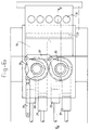
- Figure 2 shows a section along II-II of the shaping machine shown in Figure 1.
- Figure 3 shows a top view of Figure 1.
- Figure 4 shows an end view
- Figure 5 shows a side view corresponding to Figure 1 of a second embodiment of the shaping machine.
- Figure 6 shows a section along IV-IV.
- the shaping machine shown in Figures 1 - 4 has a stock container 1, consisting of two partially conical containers 2, 3 which adjoin each other with their common intersecting line 4.
- a screw element 6 is disposed in each container 2, 3. The rotary movement of these screw elements 6 is synchronized in such a way that they can move freely past each other in the region where the containers 2, 3 intersect each other.
- both containers At their bottom side, both containers have a hole 7, to which the meat mass placed in the containers is forced in a uniform manner by the screw elements 6.
- the containers 2, 3 connect with their holes 7 to respective valve elements 8, which are situated in housing 9.
- Said housing has a rectangular cross-section, as can be seen in Figure 4.
- the valve elements are accessible by way of holes 10, corresponding to the holes 7, in the top of plate 28.
- Each valve element 8 has a circular bottom base plate 11 and top base plate 38. These plates 11, 38 are accommodated in correspondingly shaped recesses in bottom wall and top wall respectively of housing 27, and are sealed with sealing rings 5.
- the channel 14 extends between said plates 11, 38. Said channel 14 has a top end which opens out concentrically relative to the top base plate 38 and hole 7 of the appropriate container.
- the passage channel also has a part bent through 90°. This bent part can connect to one of the cylinders 17, 18.
- each valve element 8 is accommodated in the housing 9 in each case between two cylinders 17, 18, on the one hand, and chamber 19, on the other hand. In the position shown, each valve element 8 shuts off cylinder 18 relative to chamber 19 and allows cylinder 17 free access to said chamber 19.
- passage channel 14 forms a connection between container 2, 3 and cylinder 18, while the connection between container 2, 3 and cylinder 17 is broken.
- pistons 20, 21 are provided in the cylinders 17, 18 respectively. These pistons can each be driven by their own drive.
- cylinders 17 are at the beginning of their suction stroke, and cylinders 18 are at the beginning of their compression stroke.
- the cylinders 18 fill up, while the pistons 20 empty the cylinders 17, and their meat mass goes into the chamber 19.
- the meat mass is then forced from the bottom through the outlet 23 into the recesses 24 in shaping plate 25.
- Said shaping plate is moved to and fro in a cycle, by means which are not shown, between the filling position, in which the recesses lie opposite outlet 23, and the ejection position, in which the recesses lie above the conveyor belt 38.
- the shaped portions are removed from the recesses 24 by means of an ejection device (not shown) and discharged on conveyor belt 38.
- sealing rings 26 are fitted, in addition to sealing rings 5.
- These sealing rings 26 are accommodated in a housing which is indicated in its entirety by 27, and which fits in a sealing manner into the chamber. Resting on the top of each housing is a plate 28, on which a container 2, 3 is disposed in each case. These plates 28 can be swung up about hinge 29, for the purpose of cleaning the shaping machine.
- valve means 8 when plate 28 is folded up the entire valve means 8 can be removed.
- the valve means is slidable, with drive shaft 31 on which key 32 is disposed, in sleeve 33 with keyway 34.
- Lever 35 is fixed to sleeve 33, which lever can in turn be operated by the hydraulic piston-cylinder unit 36.
- the levers 35 of the two valve means are connected by way of coupling rod 37, in such a way that they are always in the same position.
Abstract
Description
- The invention relates to a shaping machine for dividing a deformable mass, such as a meat product, into separately shaped portions, comprising a stock container, at least two piston-cylinder units for alternately feeding in the mass from the stock container to a shaping plate provided with shaped recesses, and also means for removing the shaped portions from the shaping plate.
- Such a shaping machine is known from US-A-4372008. In this case a meat mass is kept ready in a container, and is conveyed in the direction of a number of vertically disposed screw conveyors by means of a conveyor belt on the bottom of the container. These screw conveyors force the meat mass downwards to the entrance to the cylinders. Finally, the meat mass is pushed up into the cylinders by appropriate pistons and extruded in a shaping plate.
- In order to ensure that the meat product ultimately obtained has an acceptable texture, it is desirable to handle the meat mass carefully. Too rough handling leads to too great disintegration, which adversely affects the quality of the end product. In this respect the known shaping machine is not very satisfactory, owing to the conveyance movement produced by conveyor belt and conveyor screws. The meat mass is often compressed too much in the vicinity of the conveyor screws, while parts of said mass also carry out a circular movement.
- The object of the invention is therefore to provide a shaping machine of the above-described type which does not have these disadvantages. This is achieved through valve means being provided for connecting the cylinders alternately to the stock container. The meat mass can be fed into the appropriate cylinder by way of the valve means, which ensures a more uniform treatment. The result of this is that the texture of the meat mass remains better preserved. The two cylinders are filled alternately, and they also convey the meat mass alternately to the shaping plate. Despite the intervals in the feed per cylinder, a sufficiently constant feed for the entire shaping machine can still be obtained in this way.
- The cylinders are accommodated next to each other in a housing which has a chamber which connects to the shaping plate at one side and to the cylinders at the other side, while the valve means also operate the connection between chambers and cylinders. The valve means fulfil a dual function, namely connecting the cylinders alternately to the stock container or to the shaping plate. For this purpose, the valve means can be moved between two positions, in each of which the connection between one of the cylinders and the chamber is shut off and the connection between that cylinder and the stock container is opened each time.
- According to a preferred embodiment, a swivellable valve element is provided in the chamber, which valve element has a passage whose one end is permanently connected to the stock container by way of an opening in the top wall of the chamber, and whose other end in both positions of the valve element is connected to the appropriate cylinder in each case. The passage provides a good uniform guidance of the meat mass to the appropriate cylinder.
- The chamber can be designed with a rectangular cross-section, in that case the valve element having a bottom and top base plate with circular periphery which interacts in a sealing manner with the bottom chamber wall. The valve element also has a top base plate with circular periphery which interacts in a sealing manner with the top chamber wall.
- In order to improve the sealing action of the valve element, each base plate is accommodated in a correspondingly shaped recess in the appropriate wall of the chamber.
- The swivellable valve element can be designed in various ways. According to a preferred possibility, provision is made for a channel which is bent through 90° and one end of which is concentric in relation to each base plate, while the other end can be connected to one of the cylinders in each case.
- A special embodiment can have two pairs of piston-cylinder units and also a valve means belonging to each pair.
- Moreover, each pair of piston-cylinder units can interact with its own essentially conical stock container, which stock containers intersect each other in a common vertical plane, thus forming a common recess in their facing wall parts.
- The invention will be explained in greater detail below with reference to the examples of embodiments shown in the figures.
- Figure 1 shows a side view, partially in section, along I-I in Figure 2, of a first embodiment of the shaping machine.
- Figure 2 shows a section along II-II of the shaping machine shown in Figure 1.
- Figure 3 shows a top view of Figure 1.
- Figure 4 shows an end view.
- Figure 5 shows a side view corresponding to Figure 1 of a second embodiment of the shaping machine.
- Figure 6 shows a section along IV-IV.
- The shaping machine shown in Figures 1 - 4 has a stock container 1, consisting of two partially
conical containers screw element 6 is disposed in eachcontainer screw elements 6 is synchronized in such a way that they can move freely past each other in the region where thecontainers - At their bottom side, both containers have a
hole 7, to which the meat mass placed in the containers is forced in a uniform manner by thescrew elements 6. - The
containers holes 7 torespective valve elements 8, which are situated inhousing 9. Said housing has a rectangular cross-section, as can be seen in Figure 4. The valve elements are accessible by way ofholes 10, corresponding to theholes 7, in the top ofplate 28. - Each
valve element 8 has a circularbottom base plate 11 andtop base plate 38. Theseplates housing 27, and are sealed withsealing rings 5. Thechannel 14 extends betweensaid plates channel 14 has a top end which opens out concentrically relative to thetop base plate 38 andhole 7 of the appropriate container. The passage channel also has a part bent through 90°. This bent part can connect to one of thecylinders - As can be seen in Figure 2, each
valve element 8 is accommodated in thehousing 9 in each case between twocylinders chamber 19, on the other hand. In the position shown, eachvalve element 8 shuts offcylinder 18 relative tochamber 19 and allowscylinder 17 free access to saidchamber 19. - At the same time, in the position shown,
passage channel 14 forms a connection betweencontainer cylinder 18, while the connection betweencontainer cylinder 17 is broken. - As already mentioned,
pistons cylinders cylinders 17 are at the beginning of their suction stroke, andcylinders 18 are at the beginning of their compression stroke. During the suction stroke thecylinders 18 fill up, while thepistons 20 empty thecylinders 17, and their meat mass goes into thechamber 19. The meat mass is then forced from the bottom through theoutlet 23 into therecesses 24 in shapingplate 25. Said shaping plate is moved to and fro in a cycle, by means which are not shown, between the filling position, in which the recesses lie oppositeoutlet 23, and the ejection position, in which the recesses lie above theconveyor belt 38. The shaped portions are removed from therecesses 24 by means of an ejection device (not shown) and discharged onconveyor belt 38. - In order to prevent air from being sucked in during the piston stroke,
sealing rings 26 are fitted, in addition to sealingrings 5. These sealingrings 26 are accommodated in a housing which is indicated in its entirety by 27, and which fits in a sealing manner into the chamber. Resting on the top of each housing is aplate 28, on which acontainer plates 28 can be swung up abouthinge 29, for the purpose of cleaning the shaping machine. - Moreover, when
plate 28 is folded up the entire valve means 8 can be removed. For this purpose, the valve means is slidable, withdrive shaft 31 on whichkey 32 is disposed, insleeve 33 withkeyway 34. -
Lever 35 is fixed tosleeve 33, which lever can in turn be operated by the hydraulic piston-cylinder unit 36. Thelevers 35 of the two valve means are connected by way ofcoupling rod 37, in such a way that they are always in the same position. - In the variant shown in Figures 5 and 6 the meat mass is forced from the top into the
recesses 24 in the shaping plate. This means that thechannel 23 can be short, which has a beneficial effect on the quality of the shaped mass. Thelevers 35 are now fitted on the top side of each valve means 8.
Claims (12)
- Shaping machine for dividing a deformable mass, such as a meat product, into separately shaped portions, comprising a stock container (1), at least two piston-cylinder units (17, 18, 20, 21) for alternately feeding in the mass from the stock container to a shaping plate (25) provided with shaped recesses (24), and also means for removing the shaped portions from the shaping plate, characterized in that valve means (8) are provided for connecting the cylinders alternately to the stock container.
- Shaping machine according to Claim 1, in which the cylinders (17, 18) are accommodated next to each other in a housing (9) which has a chamber (19) connecting at one side to the shaping plate and at the other side to the cylinders, while the valve means (8) also operate the connection between chamber and cylinders.
- Shaping machine according to Claim 2, in which the valve means (8) can be moved between two positions, in each of which the connection between one of the cylinders (17, 18) and the chamber (19) is shut off and the connection between that cylinder and the stock container (1) is opened each time.
- Shaping machine according to Claim 3, in which a swivellable valve element (8) is provided in the chamber (19), which valve element has a passage whose one end is permanently connected to the stock container (1) by way of an opening in the top wall of the chamber, and whose other end in both positions of the valve element is connected to the appropriate cylinder in each case.
- Shaping machine according to Claim 4, in which the chamber (19) has a rectangular cross-section, and the valve element (8) has a bottom base plate (11) with circular periphery which interacts in a sealing manner with the bottom chamber wall.
- Shaping machine according to Claim 5, in which the valve element (8) has a top base plate (38) with circular periphery which interacts in a sealing manner with the top chamber wall.
- Shaping machine according to Claim 5 or 6, in which each base plate (11, 38) is accommodated in a correspondingly shaped recess in the appropriate wall of the chamber.
- Shaping machine according to Claim 5, 6 or 7, in which provision is made for a channel which is bent through 90° and one end of which is concentric in relation to each base plate (11, 38), while the other end can also be connected to one of the cylinders (17, 18).
- Shaping machine according to one of the preceding claims, in which the chamber (19) connects to the bottom side of the shaping plate (25).
- Shaping machine according to one of the preceding Claims 1 - 8, in which the chamber (19) connects to the top side of the shaping plate (25).
- Shaping machine according to one of the preceding claims, in which two pairs of piston-cylinder units (17, 18, 20, 21) and a valve means (8) belonging to each pair are provided.
- Shaping machine according to Claim 11, in which each pair of piston-cylinder units (17, 18, 20, 21) interacts with its own essentially conical stock container, which stock containers intersect each other in a common vertical plane, thus forming a common recess in their facing wall parts.
Applications Claiming Priority (3)
| Application Number | Priority Date | Filing Date | Title |
|---|---|---|---|
| NL9301248 | 1993-07-15 | ||
| NL9301248A NL9301248A (en) | 1993-07-15 | 1993-07-15 | Forming machine. |
| PCT/NL1994/000165 WO1995002332A1 (en) | 1993-07-15 | 1994-07-13 | Shaping machine |
Publications (2)
| Publication Number | Publication Date |
|---|---|
| EP0708601A1 EP0708601A1 (en) | 1996-05-01 |
| EP0708601B1 true EP0708601B1 (en) | 1997-01-15 |
Family
ID=19862663
Family Applications (1)
| Application Number | Title | Priority Date | Filing Date |
|---|---|---|---|
| EP94925031A Expired - Lifetime EP0708601B1 (en) | 1993-07-15 | 1994-07-13 | Shaping machine |
Country Status (10)
| Country | Link |
|---|---|
| US (1) | US5643075A (en) |
| EP (1) | EP0708601B1 (en) |
| JP (1) | JP2788123B2 (en) |
| AT (1) | ATE147584T1 (en) |
| CA (1) | CA2164191C (en) |
| DE (1) | DE69401511T2 (en) |
| DK (1) | DK0708601T3 (en) |
| ES (1) | ES2096483T3 (en) |
| NL (1) | NL9301248A (en) |
| WO (1) | WO1995002332A1 (en) |
Cited By (1)
| Publication number | Priority date | Publication date | Assignee | Title |
|---|---|---|---|---|
| WO2001041575A1 (en) | 1999-12-09 | 2001-06-14 | Osi International Foods Gmbh | Device for producing ground meat patties consisting of beef and/or pork |
Families Citing this family (10)
| Publication number | Priority date | Publication date | Assignee | Title |
|---|---|---|---|---|
| NL1003568C2 (en) * | 1996-07-11 | 1998-01-15 | Tetra Laval Food Koppens Bv | Molding system for forming a mass such as a meat mass. |
| US5730650A (en) * | 1996-08-29 | 1998-03-24 | Progressive Technology Of Wisconsin, Inc. | Food patty molding machine |
| US6592359B2 (en) | 2001-06-14 | 2003-07-15 | Osi Industries, Inc. | Multiple row meat patty forming apparatus |
| US6892901B2 (en) * | 2002-02-08 | 2005-05-17 | Automatic Bar Controls, Inc. | Sauce pumping apparatus |
| EP2127530B1 (en) | 2007-01-23 | 2012-11-14 | Formax, Inc. | Food patty molding machine |
| US20100095887A1 (en) * | 2008-10-16 | 2010-04-22 | Automatic Bar Controls, Inc. | Electronic Systems and Methods for Distributing a Food Product Over a Turntable |
| US7993049B2 (en) * | 2008-10-16 | 2011-08-09 | Automatic Bar Controls, Inc. | Turntable for on-demand mixing and distributing of a food product |
| US20100097881A1 (en) * | 2008-10-16 | 2010-04-22 | Automatic Bar Controls | Apparatus and Method for Mixing and Distributing a Food Product |
| US8342367B2 (en) * | 2008-10-16 | 2013-01-01 | Automatic Bar Controls, Inc. | Cassette and vat supply source for an on-demand mixing and distributing of a food product |
| US20160255846A1 (en) * | 2015-03-05 | 2016-09-08 | Provisur Technologies, Inc. | Patty-forming apparatus with bottom feed and bottom fill plunger |
Family Cites Families (14)
| Publication number | Priority date | Publication date | Assignee | Title |
|---|---|---|---|---|
| US3121449A (en) * | 1960-10-24 | 1964-02-18 | Marchadour Yves | Machine for filling cans or other containers |
| US3731345A (en) * | 1971-10-12 | 1973-05-08 | Hobart Mfg Co | Charging apparatus |
| US3887964A (en) * | 1972-01-24 | 1975-06-10 | Formax Inc | Food patty molding machine |
| US3964127A (en) * | 1974-12-30 | 1976-06-22 | Hollymatic Corporation | Molding apparatus |
| GB1502026A (en) * | 1975-12-24 | 1978-02-22 | Dca Food Ind | Method and apparatus for forming a shaped comestible |
| US4356595A (en) * | 1980-11-07 | 1982-11-02 | Formax, Inc. | Method and apparatus for molding food patties |
| US4597135A (en) * | 1984-02-21 | 1986-07-01 | Holly Systems, Inc. | Food patty forming method and apparatus employing two or more agitator bars |
| US4700899A (en) * | 1985-10-18 | 1987-10-20 | Marlen Research Corporation | Continuous vacuum grinding method and apparatus |
| US4801097A (en) * | 1987-12-04 | 1989-01-31 | Fitch Jr Clifford E | Food product ingredient dispensing apparatus |
| US5021025A (en) * | 1989-09-12 | 1991-06-04 | Wagner Richard C | Method and machine for making food patties |
| NL9000566A (en) * | 1990-03-12 | 1991-10-01 | Stork Titan Bv | DEVICE FOR DOSING. |
| US5022888A (en) * | 1990-05-03 | 1991-06-11 | Formax, Inc. | Co-forming apparatus for food patty molding machine |
| US5149293A (en) * | 1991-11-29 | 1992-09-22 | Lisa Gable | Brassiere accessory |
| US5149298A (en) * | 1991-12-13 | 1992-09-22 | Formax, Inc. | Vertical valve food patty molding machine |
-
1993
- 1993-07-15 NL NL9301248A patent/NL9301248A/en not_active Application Discontinuation
-
1994
- 1994-07-13 CA CA002164191A patent/CA2164191C/en not_active Expired - Fee Related
- 1994-07-13 ES ES94925031T patent/ES2096483T3/en not_active Expired - Lifetime
- 1994-07-13 JP JP7504482A patent/JP2788123B2/en not_active Expired - Fee Related
- 1994-07-13 US US08/545,803 patent/US5643075A/en not_active Expired - Fee Related
- 1994-07-13 DE DE69401511T patent/DE69401511T2/en not_active Expired - Lifetime
- 1994-07-13 DK DK94925031.0T patent/DK0708601T3/en active
- 1994-07-13 EP EP94925031A patent/EP0708601B1/en not_active Expired - Lifetime
- 1994-07-13 AT AT94925031T patent/ATE147584T1/en not_active IP Right Cessation
- 1994-07-13 WO PCT/NL1994/000165 patent/WO1995002332A1/en active IP Right Grant
Cited By (2)
| Publication number | Priority date | Publication date | Assignee | Title |
|---|---|---|---|---|
| WO2001041575A1 (en) | 1999-12-09 | 2001-06-14 | Osi International Foods Gmbh | Device for producing ground meat patties consisting of beef and/or pork |
| DE19959432B4 (en) * | 1999-12-09 | 2004-02-26 | Osi International Foods Gmbh | Device for producing minced beef and / or pork slices |
Also Published As
| Publication number | Publication date |
|---|---|
| CA2164191A1 (en) | 1995-01-26 |
| ATE147584T1 (en) | 1997-02-15 |
| JP2788123B2 (en) | 1998-08-20 |
| EP0708601A1 (en) | 1996-05-01 |
| CA2164191C (en) | 1999-03-16 |
| DK0708601T3 (en) | 1997-03-10 |
| DE69401511D1 (en) | 1997-02-27 |
| JPH08506968A (en) | 1996-07-30 |
| WO1995002332A1 (en) | 1995-01-26 |
| US5643075A (en) | 1997-07-01 |
| DE69401511T2 (en) | 1997-07-24 |
| NL9301248A (en) | 1995-02-01 |
| ES2096483T3 (en) | 1997-03-01 |
Similar Documents
| Publication | Publication Date | Title |
|---|---|---|
| EP0708601B1 (en) | Shaping machine | |
| US3887964A (en) | Food patty molding machine | |
| CA1112100A (en) | Food patty molding machine | |
| EP0489737B1 (en) | Slide plate patty forming apparatus | |
| US7309228B2 (en) | Hydraulic pump system for a patty-forming apparatus | |
| US7125245B2 (en) | Tube valve arrangement for a patty-forming machine | |
| USRE30096E (en) | Food patty molding machine | |
| US8011914B2 (en) | Food supply system for a food patty molding machine | |
| US4372008A (en) | Food patty molding machine with multi-orifice fill passage and stripper plate | |
| US4418446A (en) | Mold assembly for food patty molding machine | |
| CA2204684C (en) | Moulding system for moulding a mass, such as a mass of meat | |
| US3864891A (en) | Meat packaging and pressing apparatus and method | |
| US6454559B1 (en) | Food patty-molding apparatus having mold plate with multiple rows of cavities | |
| EP0447003A1 (en) | Device for dosing into moulds | |
| US5145454A (en) | Patty machine | |
| GB2192859A (en) | Fluid metering device with arrangement to prevent dripping from nozzle | |
| US3555592A (en) | Machine for forming and dispensing a plastic material | |
| CN114751029A (en) | Outer packing bagging and sleeving machine | |
| GR1002761B (en) | Machine for the production of shaped sweets and similar products |
Legal Events
| Date | Code | Title | Description |
|---|---|---|---|
| PUAI | Public reference made under article 153(3) epc to a published international application that has entered the european phase |
Free format text: ORIGINAL CODE: 0009012 |
|
| 17P | Request for examination filed |
Effective date: 19951102 |
|
| AK | Designated contracting states |
Kind code of ref document: A1 Designated state(s): AT BE CH DE DK ES FR GB IT LI NL SE |
|
| GRAG | Despatch of communication of intention to grant |
Free format text: ORIGINAL CODE: EPIDOS AGRA |
|
| GRAH | Despatch of communication of intention to grant a patent |
Free format text: ORIGINAL CODE: EPIDOS IGRA |
|
| 17Q | First examination report despatched |
Effective date: 19960612 |
|
| GRAH | Despatch of communication of intention to grant a patent |
Free format text: ORIGINAL CODE: EPIDOS IGRA |
|
| GRAA | (expected) grant |
Free format text: ORIGINAL CODE: 0009210 |
|
| AK | Designated contracting states |
Kind code of ref document: B1 Designated state(s): AT BE CH DE DK ES FR GB IT LI NL SE |
|
| REF | Corresponds to: |
Ref document number: 147584 Country of ref document: AT Date of ref document: 19970215 Kind code of ref document: T |
|
| REG | Reference to a national code |
Ref country code: CH Ref legal event code: NV Representative=s name: BUGNION S.A. Ref country code: CH Ref legal event code: EP |
|
| ITF | It: translation for a ep patent filed |
Owner name: BUZZI, NOTARO&ANTONIELLI D'OULX |
|
| ET | Fr: translation filed | ||
| REF | Corresponds to: |
Ref document number: 69401511 Country of ref document: DE Date of ref document: 19970227 |
|
| REG | Reference to a national code |
Ref country code: ES Ref legal event code: FG2A Ref document number: 2096483 Country of ref document: ES Kind code of ref document: T3 |
|
| REG | Reference to a national code |
Ref country code: DK Ref legal event code: T3 |
|
| PLBE | No opposition filed within time limit |
Free format text: ORIGINAL CODE: 0009261 |
|
| STAA | Information on the status of an ep patent application or granted ep patent |
Free format text: STATUS: NO OPPOSITION FILED WITHIN TIME LIMIT |
|
| 26N | No opposition filed | ||
| REG | Reference to a national code |
Ref country code: CH Ref legal event code: PFA Free format text: TETRA LAVAL FOOD KOPPENS B.V. TRANSFER- KOPPENS B.V. |
|
| REG | Reference to a national code |
Ref country code: FR Ref legal event code: CD |
|
| REG | Reference to a national code |
Ref country code: ES Ref legal event code: PC2A |
|
| REG | Reference to a national code |
Ref country code: GB Ref legal event code: IF02 |
|
| PGFP | Annual fee paid to national office [announced via postgrant information from national office to epo] |
Ref country code: ES Payment date: 20070725 Year of fee payment: 14 |
|
| PGFP | Annual fee paid to national office [announced via postgrant information from national office to epo] |
Ref country code: AT Payment date: 20070723 Year of fee payment: 14 |
|
| PGFP | Annual fee paid to national office [announced via postgrant information from national office to epo] |
Ref country code: BE Payment date: 20070724 Year of fee payment: 14 |
|
| PG25 | Lapsed in a contracting state [announced via postgrant information from national office to epo] |
Ref country code: AT Free format text: LAPSE BECAUSE OF NON-PAYMENT OF DUE FEES Effective date: 20080713 |
|
| REG | Reference to a national code |
Ref country code: ES Ref legal event code: FD2A Effective date: 20080714 |
|
| PG25 | Lapsed in a contracting state [announced via postgrant information from national office to epo] |
Ref country code: ES Free format text: LAPSE BECAUSE OF NON-PAYMENT OF DUE FEES Effective date: 20080714 |
|
| PG25 | Lapsed in a contracting state [announced via postgrant information from national office to epo] |
Ref country code: BE Free format text: LAPSE BECAUSE OF NON-PAYMENT OF DUE FEES Effective date: 20080731 |
|
| PGFP | Annual fee paid to national office [announced via postgrant information from national office to epo] |
Ref country code: DK Payment date: 20130829 Year of fee payment: 20 Ref country code: DE Payment date: 20130924 Year of fee payment: 20 Ref country code: CH Payment date: 20130829 Year of fee payment: 20 Ref country code: SE Payment date: 20130829 Year of fee payment: 20 Ref country code: NL Payment date: 20130829 Year of fee payment: 20 |
|
| PGFP | Annual fee paid to national office [announced via postgrant information from national office to epo] |
Ref country code: FR Payment date: 20130829 Year of fee payment: 20 Ref country code: GB Payment date: 20130829 Year of fee payment: 20 |
|
| PGFP | Annual fee paid to national office [announced via postgrant information from national office to epo] |
Ref country code: IT Payment date: 20130830 Year of fee payment: 20 |
|
| REG | Reference to a national code |
Ref country code: DK Ref legal event code: EUP Effective date: 20140713 |
|
| REG | Reference to a national code |
Ref country code: DE Ref legal event code: R071 Ref document number: 69401511 Country of ref document: DE Ref country code: CH Ref legal event code: PL |
|
| REG | Reference to a national code |
Ref country code: NL Ref legal event code: V4 Effective date: 20140713 |
|
| REG | Reference to a national code |
Ref country code: GB Ref legal event code: PE20 Expiry date: 20140712 |
|
| REG | Reference to a national code |
Ref country code: SE Ref legal event code: EUG |
|
| PG25 | Lapsed in a contracting state [announced via postgrant information from national office to epo] |
Ref country code: DE Free format text: LAPSE BECAUSE OF EXPIRATION OF PROTECTION Effective date: 20140715 |
|
| PG25 | Lapsed in a contracting state [announced via postgrant information from national office to epo] |
Ref country code: GB Free format text: LAPSE BECAUSE OF EXPIRATION OF PROTECTION Effective date: 20140712 |