EP0708564B1 - Method of encoder control - Google Patents
Method of encoder control Download PDFInfo
- Publication number
- EP0708564B1 EP0708564B1 EP95307225A EP95307225A EP0708564B1 EP 0708564 B1 EP0708564 B1 EP 0708564B1 EP 95307225 A EP95307225 A EP 95307225A EP 95307225 A EP95307225 A EP 95307225A EP 0708564 B1 EP0708564 B1 EP 0708564B1
- Authority
- EP
- European Patent Office
- Prior art keywords
- field
- film
- video data
- flag
- frame
- Prior art date
- Legal status (The legal status is an assumption and is not a legal conclusion. Google has not performed a legal analysis and makes no representation as to the accuracy of the status listed.)
- Expired - Lifetime
Links
- 238000000034 method Methods 0.000 title claims description 44
- 230000008859 change Effects 0.000 claims description 56
- 230000003111 delayed effect Effects 0.000 claims description 38
- 238000012545 processing Methods 0.000 claims description 18
- 238000001514 detection method Methods 0.000 claims description 17
- 238000001914 filtration Methods 0.000 claims description 15
- 238000011045 prefiltration Methods 0.000 claims description 12
- 230000004048 modification Effects 0.000 claims description 5
- 238000012986 modification Methods 0.000 claims description 5
- 230000000737 periodic effect Effects 0.000 claims description 4
- 230000007704 transition Effects 0.000 claims description 3
- 230000001934 delay Effects 0.000 claims description 2
- 230000004044 response Effects 0.000 claims description 2
- 238000005070 sampling Methods 0.000 claims description 2
- 230000003044 adaptive effect Effects 0.000 description 11
- 230000008569 process Effects 0.000 description 11
- 230000006835 compression Effects 0.000 description 5
- 238000007906 compression Methods 0.000 description 5
- 238000010586 diagram Methods 0.000 description 5
- 230000000750 progressive effect Effects 0.000 description 5
- 230000002123 temporal effect Effects 0.000 description 5
- 241000023320 Luma <angiosperm> Species 0.000 description 4
- 239000000463 material Substances 0.000 description 4
- OSWPMRLSEDHDFF-UHFFFAOYSA-N methyl salicylate Chemical compound COC(=O)C1=CC=CC=C1O OSWPMRLSEDHDFF-UHFFFAOYSA-N 0.000 description 4
- 238000006243 chemical reaction Methods 0.000 description 2
- 238000005562 fading Methods 0.000 description 2
- 230000006870 function Effects 0.000 description 2
- 230000000873 masking effect Effects 0.000 description 2
- 239000000203 mixture Substances 0.000 description 2
- 238000007781 pre-processing Methods 0.000 description 2
- 238000012360 testing method Methods 0.000 description 2
- 230000009471 action Effects 0.000 description 1
- 230000000454 anti-cipatory effect Effects 0.000 description 1
- 238000013459 approach Methods 0.000 description 1
- 230000008901 benefit Effects 0.000 description 1
- 230000002457 bidirectional effect Effects 0.000 description 1
- 238000004891 communication Methods 0.000 description 1
- 238000012937 correction Methods 0.000 description 1
- 230000004438 eyesight Effects 0.000 description 1
- 238000003780 insertion Methods 0.000 description 1
- 230000037431 insertion Effects 0.000 description 1
- NJPPVKZQTLUDBO-UHFFFAOYSA-N novaluron Chemical compound C1=C(Cl)C(OC(F)(F)C(OC(F)(F)F)F)=CC=C1NC(=O)NC(=O)C1=C(F)C=CC=C1F NJPPVKZQTLUDBO-UHFFFAOYSA-N 0.000 description 1
- 230000009467 reduction Effects 0.000 description 1
- 230000011218 segmentation Effects 0.000 description 1
- 238000012549 training Methods 0.000 description 1
- 230000016776 visual perception Effects 0.000 description 1
Images


Classifications
-
- H—ELECTRICITY
- H04—ELECTRIC COMMUNICATION TECHNIQUE
- H04N—PICTORIAL COMMUNICATION, e.g. TELEVISION
- H04N19/00—Methods or arrangements for coding, decoding, compressing or decompressing digital video signals
- H04N19/50—Methods or arrangements for coding, decoding, compressing or decompressing digital video signals using predictive coding
- H04N19/59—Methods or arrangements for coding, decoding, compressing or decompressing digital video signals using predictive coding involving spatial sub-sampling or interpolation, e.g. alteration of picture size or resolution
-
- H—ELECTRICITY
- H04—ELECTRIC COMMUNICATION TECHNIQUE
- H04N—PICTORIAL COMMUNICATION, e.g. TELEVISION
- H04N19/00—Methods or arrangements for coding, decoding, compressing or decompressing digital video signals
- H04N19/10—Methods or arrangements for coding, decoding, compressing or decompressing digital video signals using adaptive coding
- H04N19/102—Methods or arrangements for coding, decoding, compressing or decompressing digital video signals using adaptive coding characterised by the element, parameter or selection affected or controlled by the adaptive coding
- H04N19/117—Filters, e.g. for pre-processing or post-processing
-
- H—ELECTRICITY
- H04—ELECTRIC COMMUNICATION TECHNIQUE
- H04N—PICTORIAL COMMUNICATION, e.g. TELEVISION
- H04N19/00—Methods or arrangements for coding, decoding, compressing or decompressing digital video signals
- H04N19/10—Methods or arrangements for coding, decoding, compressing or decompressing digital video signals using adaptive coding
- H04N19/102—Methods or arrangements for coding, decoding, compressing or decompressing digital video signals using adaptive coding characterised by the element, parameter or selection affected or controlled by the adaptive coding
- H04N19/132—Sampling, masking or truncation of coding units, e.g. adaptive resampling, frame skipping, frame interpolation or high-frequency transform coefficient masking
-
- H—ELECTRICITY
- H04—ELECTRIC COMMUNICATION TECHNIQUE
- H04N—PICTORIAL COMMUNICATION, e.g. TELEVISION
- H04N19/00—Methods or arrangements for coding, decoding, compressing or decompressing digital video signals
- H04N19/10—Methods or arrangements for coding, decoding, compressing or decompressing digital video signals using adaptive coding
- H04N19/134—Methods or arrangements for coding, decoding, compressing or decompressing digital video signals using adaptive coding characterised by the element, parameter or criterion affecting or controlling the adaptive coding
- H04N19/136—Incoming video signal characteristics or properties
- H04N19/14—Coding unit complexity, e.g. amount of activity or edge presence estimation
-
- H—ELECTRICITY
- H04—ELECTRIC COMMUNICATION TECHNIQUE
- H04N—PICTORIAL COMMUNICATION, e.g. TELEVISION
- H04N19/00—Methods or arrangements for coding, decoding, compressing or decompressing digital video signals
- H04N19/10—Methods or arrangements for coding, decoding, compressing or decompressing digital video signals using adaptive coding
- H04N19/134—Methods or arrangements for coding, decoding, compressing or decompressing digital video signals using adaptive coding characterised by the element, parameter or criterion affecting or controlling the adaptive coding
- H04N19/142—Detection of scene cut or scene change
-
- H—ELECTRICITY
- H04—ELECTRIC COMMUNICATION TECHNIQUE
- H04N—PICTORIAL COMMUNICATION, e.g. TELEVISION
- H04N19/00—Methods or arrangements for coding, decoding, compressing or decompressing digital video signals
- H04N19/10—Methods or arrangements for coding, decoding, compressing or decompressing digital video signals using adaptive coding
- H04N19/134—Methods or arrangements for coding, decoding, compressing or decompressing digital video signals using adaptive coding characterised by the element, parameter or criterion affecting or controlling the adaptive coding
- H04N19/146—Data rate or code amount at the encoder output
- H04N19/149—Data rate or code amount at the encoder output by estimating the code amount by means of a model, e.g. mathematical model or statistical model
-
- H—ELECTRICITY
- H04—ELECTRIC COMMUNICATION TECHNIQUE
- H04N—PICTORIAL COMMUNICATION, e.g. TELEVISION
- H04N19/00—Methods or arrangements for coding, decoding, compressing or decompressing digital video signals
- H04N19/10—Methods or arrangements for coding, decoding, compressing or decompressing digital video signals using adaptive coding
- H04N19/169—Methods or arrangements for coding, decoding, compressing or decompressing digital video signals using adaptive coding characterised by the coding unit, i.e. the structural portion or semantic portion of the video signal being the object or the subject of the adaptive coding
- H04N19/17—Methods or arrangements for coding, decoding, compressing or decompressing digital video signals using adaptive coding characterised by the coding unit, i.e. the structural portion or semantic portion of the video signal being the object or the subject of the adaptive coding the unit being an image region, e.g. an object
- H04N19/172—Methods or arrangements for coding, decoding, compressing or decompressing digital video signals using adaptive coding characterised by the coding unit, i.e. the structural portion or semantic portion of the video signal being the object or the subject of the adaptive coding the unit being an image region, e.g. an object the region being a picture, frame or field
-
- H—ELECTRICITY
- H04—ELECTRIC COMMUNICATION TECHNIQUE
- H04N—PICTORIAL COMMUNICATION, e.g. TELEVISION
- H04N19/00—Methods or arrangements for coding, decoding, compressing or decompressing digital video signals
- H04N19/10—Methods or arrangements for coding, decoding, compressing or decompressing digital video signals using adaptive coding
- H04N19/169—Methods or arrangements for coding, decoding, compressing or decompressing digital video signals using adaptive coding characterised by the coding unit, i.e. the structural portion or semantic portion of the video signal being the object or the subject of the adaptive coding
- H04N19/17—Methods or arrangements for coding, decoding, compressing or decompressing digital video signals using adaptive coding characterised by the coding unit, i.e. the structural portion or semantic portion of the video signal being the object or the subject of the adaptive coding the unit being an image region, e.g. an object
- H04N19/176—Methods or arrangements for coding, decoding, compressing or decompressing digital video signals using adaptive coding characterised by the coding unit, i.e. the structural portion or semantic portion of the video signal being the object or the subject of the adaptive coding the unit being an image region, e.g. an object the region being a block, e.g. a macroblock
-
- H—ELECTRICITY
- H04—ELECTRIC COMMUNICATION TECHNIQUE
- H04N—PICTORIAL COMMUNICATION, e.g. TELEVISION
- H04N19/00—Methods or arrangements for coding, decoding, compressing or decompressing digital video signals
- H04N19/10—Methods or arrangements for coding, decoding, compressing or decompressing digital video signals using adaptive coding
- H04N19/169—Methods or arrangements for coding, decoding, compressing or decompressing digital video signals using adaptive coding characterised by the coding unit, i.e. the structural portion or semantic portion of the video signal being the object or the subject of the adaptive coding
- H04N19/179—Methods or arrangements for coding, decoding, compressing or decompressing digital video signals using adaptive coding characterised by the coding unit, i.e. the structural portion or semantic portion of the video signal being the object or the subject of the adaptive coding the unit being a scene or a shot
-
- H—ELECTRICITY
- H04—ELECTRIC COMMUNICATION TECHNIQUE
- H04N—PICTORIAL COMMUNICATION, e.g. TELEVISION
- H04N19/00—Methods or arrangements for coding, decoding, compressing or decompressing digital video signals
- H04N19/46—Embedding additional information in the video signal during the compression process
-
- H—ELECTRICITY
- H04—ELECTRIC COMMUNICATION TECHNIQUE
- H04N—PICTORIAL COMMUNICATION, e.g. TELEVISION
- H04N19/00—Methods or arrangements for coding, decoding, compressing or decompressing digital video signals
- H04N19/60—Methods or arrangements for coding, decoding, compressing or decompressing digital video signals using transform coding
- H04N19/61—Methods or arrangements for coding, decoding, compressing or decompressing digital video signals using transform coding in combination with predictive coding
-
- H—ELECTRICITY
- H04—ELECTRIC COMMUNICATION TECHNIQUE
- H04N—PICTORIAL COMMUNICATION, e.g. TELEVISION
- H04N19/00—Methods or arrangements for coding, decoding, compressing or decompressing digital video signals
- H04N19/85—Methods or arrangements for coding, decoding, compressing or decompressing digital video signals using pre-processing or post-processing specially adapted for video compression
-
- H—ELECTRICITY
- H04—ELECTRIC COMMUNICATION TECHNIQUE
- H04N—PICTORIAL COMMUNICATION, e.g. TELEVISION
- H04N19/00—Methods or arrangements for coding, decoding, compressing or decompressing digital video signals
- H04N19/10—Methods or arrangements for coding, decoding, compressing or decompressing digital video signals using adaptive coding
- H04N19/134—Methods or arrangements for coding, decoding, compressing or decompressing digital video signals using adaptive coding characterised by the element, parameter or criterion affecting or controlling the adaptive coding
- H04N19/146—Data rate or code amount at the encoder output
-
- H—ELECTRICITY
- H04—ELECTRIC COMMUNICATION TECHNIQUE
- H04N—PICTORIAL COMMUNICATION, e.g. TELEVISION
- H04N7/00—Television systems
- H04N7/01—Conversion of standards, e.g. involving analogue television standards or digital television standards processed at pixel level
- H04N7/0112—Conversion of standards, e.g. involving analogue television standards or digital television standards processed at pixel level one of the standards corresponding to a cinematograph film standard
Definitions
- This invention relates to video encoder control systems, to video encoders, and to methods for controlling a video encoder.
- Image compression systems are used to digitize video into a minimal number of bits while maintaining maximum image quality.
- the Motion Picture Experts Group (MPEG) standard defines some techniques useful in image compression. Some implementations provide for image compression in video encoders but retain redundancy in the data during the compression.
- Film material in the input video images such as images shot at 24 frames per second may be converted to 60 fields per second video in a process known in the art as 3:2 pulldown, where each video frame is recorded alternately on three fields of video and two fields of video.
- 3:2 pulldown methods result in redundancy in the conversion. Detection and removal of such redundancies may result in a removal of one field per five fields without a resulting loss of information while reducing by 20% the video image data to be stored and processed.
- 90% of prime time television material is derived from film sources, such a reduction of video image data of 20% without incurring a loss of image information significantly saves data capacity in video encoding.
- the erroneous placement of intra frames may result in lesser quality in subsequent decoding.
- regular video frames are generally predicted from at least the previous frame, with intra frames sent periodically to a receiver facilitating the receiver's acquisition of the video images.
- Such intra frames as well as frames from scene changes generally require more bits to encode than regular video frames, especially since scene changing frames are effectively unpredictable frames. If an intra frame occurs just before or just after a scene change, the average bit rate required for encoding may increase to a level that the quality of the encoding is reduced, resulting in subsequent visible artifacts upon decoding.
- a video encoder control system for controlling a video encoder, including a processor having a multiple field delay circuit for delaying input video data by a predetermined number N, N > 1, to generate delayed video data; a statistics generator for processing the input video data to generate statistics of a first frame and successive frames and to generate a control signal from the statistics; an encoder module; and a rate controller which responds to the control signal to control the encoding of the delayed video data corresponding to the first frame by the encoder module.
- the statistics generator calculates a sum of absolute values of differences between field pixels and calculates subsampled low pass filter image values; and a pulldown detector is included which uses the sum for detecting a redundant field in the associated fields, for generating a redundancy flag as the control signal corresponding to the redundant field.
- a scene change detector is included which uses the sums for detecting a scene change from the first frame and a successive frame and for generating a scene change flag as the control signal.
- the statistics generator also determines an average pixel value of each frame; and a fade detector uses the average pixel values of the first field and the successive fields to determine a video fade.
- a resolution selector which uses the sum to generate a resolution select signal which the rate controller uses to change the resolution of the encoding of the successive frame.
- the outputs of the processor including film flags, scene change flags, and fade flags, to the rate controller to control the encoding of the delayed video data.
- a method for controlling a video encoder to encode input video data corresponding to a plurality of frames.
- the method includes the steps of delaying the input video data by a predetermined number N of frames, N > 1, as delayed video data; processing the input video data to generate statistics of the first video frame; and controlling the encoding of the delayed video data corresponding to the first frame by the video encoder using the statistics.
- the present disclosure relates to a video encoder control system and method for detecting and effecting changes in video frames in a video encoder 10.
- blocks of pixels are arranged in lines and rows to constitute an image.
- Each pixel is associated with three components: luminance Y, red color difference C r , and blue color difference C b .
- Video data arranged in fields operating at 59.94 Hz (about 60) for video in the National Television System Committee (NTSC) standard and at 50 Hz for video in the Phase Alternation Line (PAL) standard.
- NTSC National Television System Committee
- PAL Phase Alternation Line
- pairs of fields are arranged in frames, in which FIELD1 refers to the first field to be displayed in time, known as an odd field, and FIELD2 refers to the second field to be displayed, known as an even field.
- each field is associated with a parity; i.e. even or odd.
- Such fields may also be categorized as intra fields (I fields), predictive fields (P fields), and bidirectional fields (B fields), with frames designated in like manner as I frames, P frames, and B frames.
- I fields intra fields
- P fields predictive fields
- B fields bidirectional fields
- the encoder 10 includes an encoder control module 11 for receiving commands and other inputs from an input device (not shown), a preprocessor 12 for detecting film frames and scene changes in a video input; a rate controller 14; an encoder module 16; a prediction module 18; a formatter 20; a perceptual model module 22; a motion estimation module 24; and a decoder module 26.
- an encoder control module 11 for receiving commands and other inputs from an input device (not shown), a preprocessor 12 for detecting film frames and scene changes in a video input; a rate controller 14; an encoder module 16; a prediction module 18; a formatter 20; a perceptual model module 22; a motion estimation module 24; and a decoder module 26.
- These components of the video encoder 10 may be implemented in a manner known in the art, as described, for example, in U.S. Patent Nos.
- the preprocessor 12 receives input video data and command inputs processed by the encoder control module 11 and removes redundant fields from video data corresponding to a film source.
- the rate controller 14 receives data signals such as flags from the preprocessor 12 to control the operation of the encoder 10 for performing encoding functions.
- the rate controller 14 also controls communications of the encoder 10 with external systems in order to maintain the encoded bit rate within an operating bandwidth.
- the encoder module 16 receives processed video data from the preprocessor 12 as well as prediction estimates from the prediction module 18 for encoding the preprocessed video data.
- the formatter 20 combines the various data fields with blocks of pixels of video frames to generate an encoded output signal for output through an output channel.
- the perceptual model module 22 calculates coding parameters for the encoding process, and the motion estimation module 24 performs block matching of video data in a current block of pixels with previous image data to generate motion factors.
- the decoder module 26 generates a reconstructed prediction error from the encoding process to construct a decoded image.
- the preprocessor 12 includes a look-up table module 28 which receives input video data in the CCIR-601 standard format for performing optional gamma correction, pedestal adjustment, contrast enhancement, and the like in a manner known in the art. Separate tables are maintained in the look-up table module 28 for luma and chroma signals. The input video signal passes through the look-up table module 28 to a vertical cropping module 30 which crops the input video data.
- the input video data is cropped to 480 lines.
- the input video data is cropped to 576 lines, in which all 576 active lines are used.
- the vertical cropping module 30 may crop the input video data in accordance with the requirements of the particular video standard in use, such as high definition television standards (HDTV), EGA, VGA, Super VGA, etc.
- HDTV high definition television standards
- EGA EGA
- VGA VGA
- Super VGA etc.
- MPEG standard is discussed in MPEG TEST MODEL 4, "Coded Representation of Picture and Audio Information", ISO-IEC/JTC1/SC29/EG11, CCITT SG XV, Working Party XV/1, Document AVC-445b, February 1993.
- the vertically cropped video data is received by the 3:2 pulldown processor 32 for processing to detect 3:2 pulldown and to reorder and remove input data fields such as redundant fields to generate 24 frame per second progressive video data.
- the 3:2 pulldown processor 32 performs such 3:2 pulldown, reordering, and removal of fields in a manner known in the art; for example, as described in U.S. Patent No. 5,317,398 to Casavant et al. which is incorporated herein by reference.
- the 3:2 pulldown processor 32 generates delayed video data, and other functions of the 3:2 pulldown processor 32 are described hereafter in reference to FIG. 3.
- the delayed video data from the 3:2 pulldown processor 32 is received by the vertical filter and subsampler 34 for performing chroma subsampling.
- Subsampling is herein defined to include sampling by a factor of 1.
- the encoding module 16 of the encoder 10 encodes 4:2:0 video data in a manner known in the art; for example, as described in U.S. Patent Nos. 5,253,056 to Puri et al. and 5,270,813 to Puri et al., each of which is incorporated herein by reference.
- the chroma channel resolution is half of the luma resolution in both the horizontal and vertical directions.
- the vertical filter and subsampler 34 processes the chroma channels for use by the encoder 10.
- the 3:2 pulldown processor 32 indicates such a film condition or a non-film condition by a film flag, as disclosed hereafter.
- the vertical filter and subsampler 34 responds to the film flag to process the delayed film data such that the video data as progressive film is chroma filtered on a frame basis using a predetermined four tap filter. If the video data is interlaced video data (and thus not progressive film data), the video data is encoded at a full temporal rate with vertical chroma filtering performed on each field independently. In the exemplary embodiment, odd fields are filtered by a predetermined seven tap filter and even fields are filtered by the predetermined four tap filter with the predetermined tap filters being symmetrical.
- the chroma filtered video data from the vertical filter and subsampler 34 is processed by an adaptive prefilter 36, by a horizontal filter and subsampler 38, and then by a horizontal cropping module 40 to generate preprocessed video data which is output to the encoding module 16 shown in FIG. 1.
- the operations of the adaptive prefilter 36, the horizontal filter and subsampler 38, and the horizontal cropping module 40 are describe hereafter in reference to FIG. 5.
- the 3:2 pulldown processor 32 detects redundant fields in the vertically cropped input video data.
- 3:2 pulldown is used in displaying films recorded at 24 frames per second on a NTSC television system operating at about 60 Hz, and is achieved by displaying alternating frames of film either for 1/20 th second or for 1/30 th second, while an NTSC television camera records either 3 or 2 fields for each film frame, respectively, in a manner known in the art.
- redundant fields are created.
- the 3:2 pulldown processor 32 receives the input video data and generates delayed video data by delaying the input video data by a predetermined number of fields N, where N > 1.
- N a predetermined number of fields
- each of a first field delay 42 and a second field delay 44 delays the input video data by one field to generated a resultant two field delayed video data.
- the two field delayed video data is then delayed by an 8 field delay 46 to generate the delayed video data which is thus the input video data delayed by a total of 10 fields; i.e. 5 frames.
- a statistics generator 48 receives both the input data and the two field delayed data from the second field delay 44 to generate statistics therefrom.
- the inter frame statistics and the delayed video data which is delayed five frames in the exemplary embodiment, enables the encoder module 16 to process the statistics and to adjust the subsequent encoding of the delayed video data.
- the statistics are used to categorize the incoming video data by control signals such as flags and other data signals, and to enhance any compression in the encoding process by providing a look-ahead capability of the encoder 10.
- the encoder 10, in using such statistics, flags, and the like, is then able to remove redundancies in the input video signal and to anticipate and takes preventative action before encoding relatively difficult sections of video images such as a scene change in the video images. From instructions of the rate controller 14 responding to flags and other indicators from the preprocessor 12 indicating film or scene changes, the encoder 10 may reschedule or align the next intra frame, thus improving encoded image quality.
- the input video data corresponds to fields of video pixels having associated Y, C b , and C r values, from which the statistics generator 48 calculates the following statistics for every input video field:
- the statistics generator 48 may include digital signal processing means such as a digital signal processing (DSP) circuit or chip, which may be embodied as the DSP 1610 chip available from AT&T Corp.
- digital signal processing software known in the art or other equivalent digital signal processing means may be used by the statistics generator 48 for determining the above statistics which are used to by a pulldown detector 50, a scene change detector 52, and a fade detector 53.
- the statistics generator 48 receives the input data and two-field delayed input data.
- the statistics generator 48 includes a first absolute difference calculator 54 for generating absolute values of differences between the input data and the two-field delayed input data, and a first calculator 56 uses the absolute values to generate a sum of the absolute values over a field. The sum is then output to the pulldown detector 50 and the scene change detector 52.
- the statistics generator 48 also includes first and second low pass filter and subsamplers 58, 60 which receive the input data and the two-field delayed input data, respectively.
- the subsampled low pass filtered image values generated therefrom are output to a second absolute difference calculator 62 to generate absolute values of the differences between the low pass filtered image values.
- a maximum detector 64 determines the maximum absolute value over a field and the maximum absolute value is output to the pulldown detector 50.
- the statistics generator 48 also includes an average calculator 66 which determines the average value of the input data over a field, and the average value is output to the fade detector 53.
- the following exemplary embodiments of the disclosed video encoder control system and method illustrate the use of statistics generated from the incoming video data to detect film data, scene changes, and video fading, and to adapt the encoding resolution.
- the pulldown detector 50 of the 3:2 pulldown processor 32 detects film data present in the incoming video data using the sum of absolute differences between pixels between alternating fields in the incoming video data.
- Video data of a still or redundant field causes the statistics generator 48 to generate relatively low sums of absolute differences, while video data of a stationary image causes the statistics generator 48 to generate sums of absolute differences which approach zero.
- the video data was generated from converting film images by 3:2 conversion, for every five fields, the sum from the fifth field is relatively small, while the sums from the remaining four of the five fields are relatively large.
- the pulldown detector 50 detects the presence of film in the video data by comparing the relative values of the sums generated therefrom to differ by a first predetermined value, causing the pulldown detector 50 to generate a film flag which is sent to the rate controller 14.
- the pulldown detector 50 uses the sum of absolute differences and the maximum absolute differences of the low pass filtered images calculated by the statistics generator to detect redundant video fields. Based on the location of redundant fields, a group of 10 fields are classified either as film or as non-film.
- the sum of absolute differences between a pair of input fields measures the relative mismatch between the pair of fields in a macro scale.
- the sum of absolute differences has a small value only if there is a redundant field in the pair.
- the maximum absolute differences of the low pass filtered images measures the relative mismatch in local regions of the pair of input fields.
- the maximum absolute difference has a small value only if there is a redundant field in the pair.
- the fifth field and the tenth field in a group of ten fields are redundant fields.
- the mismatch measure between the 6 th field and the 8 th field is relatively close to the mismatch measure between the 7 th field and the 9 th field.
- the mismatch measure between the 4 th field and the 6 th field is relatively close to the mismatch measure between the 5 th field and the 7 th field
- the mismatch measure between the first field and the third field is relatively close to the mismatch measure between the second field and the fourth field.
- the pulldown detector 50 maintains six internal statistic first-in-first-out (FIFO) queues having a length of eight units to store statistics of the ten most recent input fields, with the queues as follows:
- the pulldown detector 50 also maintains a state variable ⁇ which indicates the film mode of the field that is most recently output from the 8 field delay circuit 46.
- the state variable ⁇ is defined as zero if the most recently processed field is non-film, and ⁇ takes on one of the values in the range from 1 to 10 which indicates the order of the output field in the ten field 3:2 pulldown pattern. Initially, ⁇ is set to zero.
- the pulldown detector 50 uses the following statistics:
- the pulldown detector 50 performs film detection as described below, otherwise the pulldown detector 50 does not perform film detection and increases ⁇ by 1.
- the pulldown detector 50 declares the next ten fields output from the 8 field delay circuit 46 to be film if and only if all of the following conditions in Eq. (1)-(4) are met: where T Y , T Cr , T Cb , t Y , t Cr , t Cb , R Y , R Cr , R Cb , R Y ', R Cr ', and R Cb ' are thresholds which may be preset or determined by a priori knowledge of the input data. For example, the thresholds may be set by user input commands or by a set of training data.
- ⁇ is set to 1 and the next 10 fields output from the 8 field delay circuit 46 is classified as film. Otherwise, ⁇ is set to zero and the next two fields output from the 8 field delay circuit 46 is classified as non-film (i.e. video) and the above detection process is repeated for new input data.
- the pulldown detector 50 also generates a two bit mode order value, having values 0-3 (base 10) to indicate to the rate controller 14 the reconstruction of the frames, as illustrated in Table 1 below: FILM MODE ORDER VALUE DESCRIPTION 0 FIELD1/FIELD2 1 FIELD2/FIELD1 2 FIELD1/FIELD2/REPEAT FIELD1 3 FIELD2/FIELD1/REPEAT FIELD2
- the statistics generator 48 passes information to the scene change detector 50 that detects the occurrences of instantaneous changes in the scenes, or "cuts", in the input video.
- the sum of absolute differences between pixels in the current and two-field delayed fields is used to categorize the amount of change between fields.
- this parameter is normally small and varies slowly over several frames, even in scenes with apparently unpredictable motion. A scene may therefore be determined to be continuous if all field differences are below a predetermined threshold, T LOW , and vary between successive values by a small amount ⁇ T LOW .
- this parameter becomes relatively large since the two fields that are used to calculate the field differences occur in different scenes.
- the field differences are normally larger than a predetermined threshold T HIGH .
- T HIGH a predetermined threshold
- the detection of a scene change is therefore determined with high confidence when at least two high field differences are detected which are preceded and succeeded by relatively low field differences.
- the look-ahead nature of the statistics generator 48 allows the detection of a number of succeeding field differences to be proceeded in order to improve the reliability of the scene detection.
- the scene change may be detected one or more frame times before the scene change enters the encoder module 16 to be encoded. This allows the encoder 10 to change encoding parameters prior to the scene change; for example, for reducing the encoding quality of the frames before the scene change, which may not cause a change in video quality visible to the viewer of the decoded video, while improving encoding efficiency of the encoder 10.
- a scene change flag may indicate a picture type such as an intra coding setting.
- an intra frame flag may be generated and sent to the rate controller 14 to intra code the entire frame.
- Intra frame flags may also be output from the scene change detector 52 as an alternative resynchronization method.
- the statistics generator 48 includes a counter (not shown) for generating a periodic count, and the preprocessor 12 responds to the periodic count for generating an intra frame flag at regular intervals.
- the preprocessor 12 responds to the scene change flag to generate the intra frame flag
- the rate controller 14 responds to the intra frame flag for inserting an intra frame into the plurality of frames at a position corresponding to a scene change.
- the scene change detector 52 chooses to alter the frequency of intra frames according to the relative position of a scene change to make an intra frame and a scene change coincident, where the preprocessor 12 responds to the scene change flag to modify the count of the counter and to generate the intra frame flag upon the modification of the count.
- the scene change detector 52 may also output a value, such as an 8-bit value, to the rate controller 14 to indicate the probability or "strength" of a scene change.
- the 8-bit value may also indicate other scene changes such as partial scene changes.
- the 3:2 pulldown processor 32 may also insert intra frames at regular intervals to allow for insertion of commercials and I/P frame coding as an alternative to progressive refresh implementations.
- the fade detector 53 determines a video fade in the video data.
- the presence of a video fade added to a film as well as the fade rate may cause transitions from film to film or film to video to generate a false detection of the film.
- the fade detector 53 detects such video transitions from the statistics using the average pixel value as an indication of a relatively large change in brightness of the scene before and after a fade.
- the fade detector 53 responds to the average pixel values being less than a predetermined value to generate a fade flag indicating a fade in the video.
- the video encoder control system adapts the resolution of the encoding in response to changes in scenes as measured by frame statistics.
- the statistics generator 48 of the 3:2 pulldown processor 32 generates the sums of absolute field differences of pixels of the input video data as a measure of the complexity of the corresponding image. Alternatively, variances of the pixels between fields may be calculated.
- the sums are sent to the rate controller 14 which determines if the sums have exceeded a predetermined value. If the predetermined value is exceeded; i.e. the complexity of the images to be encoded is relatively high, then the rate controller 14 generates a resolution select flag to reduce the resolution of the encoded image, as described hereafter.
- the input video data is processed by the adaptive prefilter 36 in the exemplary embodiment using a first predetermined bank of 256 sets of filter values or coefficients selected by the rate controller 14 using a prefilter select signal at a rate of once every frame.
- the adaptive prefilter 36 also receives the film flag from the 3:2 pulldown processor 32 which indicates whether the input video data corresponds to progressive film or interlaced video.
- the adaptive prefilter 36 uses the film flag to select filter values from a second predetermined bank of sets of filter values.
- the film mode flag and the prefilter select signals are processed by an 8 ⁇ 8 filter 68 which is a set of 8 horizontal scan line taps and 8 vertical taps to perform 8 ⁇ 8 filtering on a frame basis.
- the taps of the 8 ⁇ 8 filter are programmable. For example, the taps on every other row may be set to zero, thus reducing the 8 ⁇ 8 filter to an 8 ⁇ 4 filter that may be applied to the pixels of a frame to perform field filtering, with only values from one of the two fields per frame are involved in the computation of the corresponding output value of the filter 68.
- the filter 68 When the film flag is off, the filter 68 operates as an 8 ⁇ 4 filter for filtering on a field basis. When the film flag is on, the filter 68 performs 8 ⁇ 8 filtering on a frame basis with the restriction on the taps; i.e. alternate rows of taps being set to zero, is removed.
- the prefiltering is adaptively performed on a field basis for video material and on a frame basis for film material.
- a plurality of filters i.e. sets of filter values or coefficients, are provided for each type of filtering, such as field basis filtering and frame basis filtering.
- the plurality of filters are determined by different settings of the taps of the 8 ⁇ 8 filter 68.
- the filter 68 is adaptive by selecting from one of a set of frame filter values or a set of field filter values depending on the difficulty to encode the video data based on the complexity of the video images as well as the state of the encoder 10.
- the scene complexity may be measured by the sum of the absolute values of the field differences in successive fields of the same parity.
- the filter 68 uses the sums of absolute values of field differences as well as an encoder bit rate set by the rate controller 14 to select at least one of the plurality of filter values for filtering the delayed video data.
- the predetermined sets of filter values may be negative, possible overflow conditions in the filtering is avoided by clamping or latching the output of the 8 ⁇ 8 filter 68 using a clamp 70 to within an 8-bit range of 0 to 256.
- Each of the Y, C b , and C r values are filtered independently with different sets of filter values in the above described manner.
- the adaptive prefilter 36 outputs clamped data of 720 pixels which are processed by a 2:1 horizontal subsampler 38.
- the 2:1 horizontal subsampler 38 responds to the resolution select flag from the rate controller 14 to determine the rate of subsampling.
- a 704 mode and a 352 mode are supported. If the 704 mode is selected, the 2:1 horizontal subsampler 72 is disabled, and the processed video data having 704 pixels per line is input to the 2:1 horizontal subsampler 72 and passes through unchanged. If the 352 mode is selected, the Y, C b , and C r values are subsampled by a factor of two, with the first pixel of each line remaining, to provide 352 pixels per line of resolution.
- the vertical filter and subsampler 34 performs adaptive filtering using the film flag in a manner as described above to perform frame or field filtering.
- the vertical filter and subsampler 34 thus performs chroma downsampling to convert 4:2:2 chroma to 4:2:0 chroma, depending on whether the video data to be processed is film or video material as determined by the 3:2 pulldown processor 32 by the film flag.
- the above resolution control method may also be used in conjunction with the adaptive prefilter 36 described above to provide a finer control of the resolution.
- the encoder 10 may be controlled to prepare for scene changes by increasing the resolution using the resolution select flag and reducing the number of bits allocated to at least one frame prior to the scene change to reduce the generation of artifacts in the encoding process.
- the above disclosed resolution control method may be used with other encoding methods to choose an encoding method for the I, P or B frames to provide sufficient resolution.
- the step of preprocessing includes the steps of delaying the video data by N frames where N > 1, to generate delayed video data in step 80; generating statistics from the input video data in step 82; processing the statistics to generate flags, including scene change flags, film flags, and video fade flags in step 84; and determining resolution settings from the statistics in step 86.
Landscapes
- Engineering & Computer Science (AREA)
- Multimedia (AREA)
- Signal Processing (AREA)
- Physics & Mathematics (AREA)
- Algebra (AREA)
- General Physics & Mathematics (AREA)
- Mathematical Analysis (AREA)
- Mathematical Optimization (AREA)
- Pure & Applied Mathematics (AREA)
- Compression Or Coding Systems Of Tv Signals (AREA)
- Compression Of Band Width Or Redundancy In Fax (AREA)
- Television Systems (AREA)
Description
- This invention relates to video encoder control systems, to video encoders, and to methods for controlling a video encoder.
- Image compression systems are used to digitize video into a minimal number of bits while maintaining maximum image quality. The Motion Picture Experts Group (MPEG) standard defines some techniques useful in image compression. Some implementations provide for image compression in video encoders but retain redundancy in the data during the compression.
- Film material in the input video images such as images shot at 24 frames per second may be converted to 60 fields per second video in a process known in the art as 3:2 pulldown, where each video frame is recorded alternately on three fields of video and two fields of video. However, 3:2 pulldown methods result in redundancy in the conversion. Detection and removal of such redundancies may result in a removal of one field per five fields without a resulting loss of information while reducing by 20% the video image data to be stored and processed. As it has been estimated that 90% of prime time television material is derived from film sources, such a reduction of video image data of 20% without incurring a loss of image information significantly saves data capacity in video encoding.
- In attempting to detect and remove such redundancies in image fields, false detection of 3:2 pulldown in mixtures of film and video or mixtures of different films may result in unacceptable reconstruction artifacts in subsequent processing of the compressed images, such as image decoding.
- In addition, the anticipation of changes in incoming video and corresponding modification of encoding parameters thereof is known in the art. In such anticipatory methods, the erroneous placement of intra frames; i.e. refresh frames or I frames, may result in lesser quality in subsequent decoding. For example, regular video frames are generally predicted from at least the previous frame, with intra frames sent periodically to a receiver facilitating the receiver's acquisition of the video images. Such intra frames as well as frames from scene changes generally require more bits to encode than regular video frames, especially since scene changing frames are effectively unpredictable frames. If an intra frame occurs just before or just after a scene change, the average bit rate required for encoding may increase to a level that the quality of the encoding is reduced, resulting in subsequent visible artifacts upon decoding.
- IEEE TRANSACTIONS ON IMAGE PROCESSING, vol. 3, no. 5, 1 September 1994, pages 513-526, LEE J ET AL; 'Temporally adaptive motion interpolation exploiting temporal masking in visual perception' presents an algorithm and a technique to dynamically adapt motion interpolation structures by temporal segmentation. The number of reference frames and the intervals between them are adjusted according to the temporal variation of the input video. Bit-rate control for this dynamic group of pictures is achieved by taking advantage of temporal masking in human vision.
- According to one aspect of this invention there is provided a video encoder control system as claimed in
claim 1. - According to another aspect of this invention there is provided a video encoder as claimed in claim 17.
- According to a further aspect of this invention there is provided a method as claimed in claim 25.
- A video encoder control system is disclosed for controlling a video encoder, including a processor having a multiple field delay circuit for delaying input video data by a predetermined number N, N > 1, to generate delayed video data; a statistics generator for processing the input video data to generate statistics of a first frame and successive frames and to generate a control signal from the statistics; an encoder module; and a rate controller which responds to the control signal to control the encoding of the delayed video data corresponding to the first frame by the encoder module. The statistics generator calculates a sum of absolute values of differences between field pixels and calculates subsampled low pass filter image values; and a pulldown detector is included which uses the sum for detecting a redundant field in the associated fields, for generating a redundancy flag as the control signal corresponding to the redundant field.
- A scene change detector is included which uses the sums for detecting a scene change from the first frame and a successive frame and for generating a scene change flag as the control signal. The statistics generator also determines an average pixel value of each frame; and a fade detector uses the average pixel values of the first field and the successive fields to determine a video fade.
- A resolution selector is provided which uses the sum to generate a resolution select signal which the rate controller uses to change the resolution of the encoding of the successive frame. The outputs of the processor, including film flags, scene change flags, and fade flags, to the rate controller to control the encoding of the delayed video data.
- A method is also disclosed for controlling a video encoder to encode input video data corresponding to a plurality of frames. The method includes the steps of delaying the input video data by a predetermined number N of frames, N > 1, as delayed video data; processing the input video data to generate statistics of the first video frame; and controlling the encoding of the delayed video data corresponding to the first frame by the video encoder using the statistics.
- The features of the disclosed video encoder control system and method will become more readily apparent and may be better understood by referring to the following detailed description of an illustrative embodiment of the present invention, taken in conjunction with the accompanying drawings, where:
- FIG. 1 is a block diagram of the disclosed video encoder;
- FIG. 2 is a block diagram of a preprocessor;
- FIG. 3 is a block diagram of a 3:2 pulldown processor in FIG. 2;
- FIG. 4 is a block diagram of the statistics generator of the 3:2 pulldown processor of FIG. 2;
- FIG. 5 is a block diagram of components of the preprocessor in FIG. 2; and
- FIG. 6 is a flow chart of the method and operation of the disclosed video encoder control system.
-
- Referring now in specific detail to the drawings, with like reference numerals identifying similar or identical elements, as shown in FIG. 1, the present disclosure relates to a video encoder control system and method for detecting and effecting changes in video frames in a
video encoder 10. - As known in the art and used throughout the following disclosure, blocks of pixels (or pels) are arranged in lines and rows to constitute an image. Each pixel is associated with three components: luminance Y, red color difference Cr, and blue color difference Cb. Video data arranged in fields operating at 59.94 Hz (about 60) for video in the National Television System Committee (NTSC) standard and at 50 Hz for video in the Phase Alternation Line (PAL) standard. Under NTSC and PAL standards, pairs of fields are arranged in frames, in which FIELD1 refers to the first field to be displayed in time, known as an odd field, and FIELD2 refers to the second field to be displayed, known as an even field. Thus, each field is associated with a parity; i.e. even or odd.
- Such fields may also be categorized as intra fields (I fields), predictive fields (P fields), and bidirectional fields (B fields), with frames designated in like manner as I frames, P frames, and B frames.
- As shown in the exemplary embodiment of FIG. 1, the
encoder 10 includes anencoder control module 11 for receiving commands and other inputs from an input device (not shown), apreprocessor 12 for detecting film frames and scene changes in a video input; arate controller 14; anencoder module 16; aprediction module 18; aformatter 20; aperceptual model module 22; amotion estimation module 24; and adecoder module 26. These components of thevideo encoder 10 may be implemented in a manner known in the art, as described, for example, in U.S. Patent Nos. 5,144,423 to Knauer et al.; 5,231,484 to Gonzales at al.; 5,247,363 to Sun et al.; 5,293,229 to Iu; and 5,325,125 to Naimpally et al., each of which are incorporated herein by reference. - Generally, for the video encoder control system and method disclosed herein, the
preprocessor 12 receives input video data and command inputs processed by theencoder control module 11 and removes redundant fields from video data corresponding to a film source. Therate controller 14 receives data signals such as flags from thepreprocessor 12 to control the operation of theencoder 10 for performing encoding functions. Therate controller 14 also controls communications of theencoder 10 with external systems in order to maintain the encoded bit rate within an operating bandwidth. Theencoder module 16 receives processed video data from thepreprocessor 12 as well as prediction estimates from theprediction module 18 for encoding the preprocessed video data. Theformatter 20 combines the various data fields with blocks of pixels of video frames to generate an encoded output signal for output through an output channel. - The
perceptual model module 22 calculates coding parameters for the encoding process, and themotion estimation module 24 performs block matching of video data in a current block of pixels with previous image data to generate motion factors. Thedecoder module 26 generates a reconstructed prediction error from the encoding process to construct a decoded image. - As illustrated in FIG. 2 for an exemplary embodiment, the
preprocessor 12 includes a look-up table module 28 which receives input video data in the CCIR-601 standard format for performing optional gamma correction, pedestal adjustment, contrast enhancement, and the like in a manner known in the art. Separate tables are maintained in the look-uptable module 28 for luma and chroma signals. The input video signal passes through the look-uptable module 28 to avertical cropping module 30 which crops the input video data. - For example, to process input video data in the NTSC standard, the input video data is cropped to 480 lines. For processing input video data in the PAL standard, the input video data is cropped to 576 lines, in which all 576 active lines are used. It is understood that the
vertical cropping module 30 may crop the input video data in accordance with the requirements of the particular video standard in use, such as high definition television standards (HDTV), EGA, VGA, Super VGA, etc. Such standards are known in the art. For example, the MPEG standard is discussed in MPEG TEST MODEL 4, "Coded Representation of Picture and Audio Information", ISO-IEC/JTC1/SC29/EG11, CCITT SG XV, Working Party XV/1, Document AVC-445b, February 1993. - For video data from NTSC sources, the vertically cropped video data is received by the 3:2
pulldown processor 32 for processing to detect 3:2 pulldown and to reorder and remove input data fields such as redundant fields to generate 24 frame per second progressive video data. The 3:2pulldown processor 32 performs such 3:2 pulldown, reordering, and removal of fields in a manner known in the art; for example, as described in U.S. Patent No. 5,317,398 to Casavant et al. which is incorporated herein by reference. In the disclosed exemplary embodiment, the 3:2pulldown processor 32 generates delayed video data, and other functions of the 3:2pulldown processor 32 are described hereafter in reference to FIG. 3. - Referring back to FIG. 2, the delayed video data from the 3:2
pulldown processor 32 is received by the vertical filter andsubsampler 34 for performing chroma subsampling. Subsampling is herein defined to include sampling by a factor of 1. - In an exemplary embodiment, the
encoding module 16 of theencoder 10 encodes 4:2:0 video data in a manner known in the art; for example, as described in U.S. Patent Nos. 5,253,056 to Puri et al. and 5,270,813 to Puri et al., each of which is incorporated herein by reference. In the exemplary embodiment, the chroma channel resolution is half of the luma resolution in both the horizontal and vertical directions. For input video data in a 4:2:2 format, the vertical filter andsubsampler 34 processes the chroma channels for use by theencoder 10. - If the delayed video data corresponds to film or non-film, the 3:2
pulldown processor 32 indicates such a film condition or a non-film condition by a film flag, as disclosed hereafter. The vertical filter andsubsampler 34 responds to the film flag to process the delayed film data such that the video data as progressive film is chroma filtered on a frame basis using a predetermined four tap filter. If the video data is interlaced video data (and thus not progressive film data), the video data is encoded at a full temporal rate with vertical chroma filtering performed on each field independently. In the exemplary embodiment, odd fields are filtered by a predetermined seven tap filter and even fields are filtered by the predetermined four tap filter with the predetermined tap filters being symmetrical. - The chroma filtered video data from the vertical filter and
subsampler 34 is processed by anadaptive prefilter 36, by a horizontal filter andsubsampler 38, and then by ahorizontal cropping module 40 to generate preprocessed video data which is output to theencoding module 16 shown in FIG. 1. The operations of theadaptive prefilter 36, the horizontal filter andsubsampler 38, and thehorizontal cropping module 40 are describe hereafter in reference to FIG. 5. - Referring to FIG. 3, the 3:2
pulldown processor 32 detects redundant fields in the vertically cropped input video data. 3:2 pulldown is used in displaying films recorded at 24 frames per second on a NTSC television system operating at about 60 Hz, and is achieved by displaying alternating frames of film either for 1/20th second or for 1/30th second, while an NTSC television camera records either 3 or 2 fields for each film frame, respectively, in a manner known in the art. In the 3:2 pulldown process, redundant fields are created. - The 3:2
pulldown processor 32 receives the input video data and generates delayed video data by delaying the input video data by a predetermined number of fields N, where N > 1. In the exemplary embodiment, each of afirst field delay 42 and asecond field delay 44 delays the input video data by one field to generated a resultant two field delayed video data. The two field delayed video data is then delayed by an 8field delay 46 to generate the delayed video data which is thus the input video data delayed by a total of 10 fields; i.e. 5 frames. - A
statistics generator 48 receives both the input data and the two field delayed data from thesecond field delay 44 to generate statistics therefrom. - The inter frame statistics and the delayed video data, which is delayed five frames in the exemplary embodiment, enables the
encoder module 16 to process the statistics and to adjust the subsequent encoding of the delayed video data. The statistics are used to categorize the incoming video data by control signals such as flags and other data signals, and to enhance any compression in the encoding process by providing a look-ahead capability of theencoder 10. Theencoder 10, in using such statistics, flags, and the like, is then able to remove redundancies in the input video signal and to anticipate and takes preventative action before encoding relatively difficult sections of video images such as a scene change in the video images. From instructions of therate controller 14 responding to flags and other indicators from thepreprocessor 12 indicating film or scene changes, theencoder 10 may reschedule or align the next intra frame, thus improving encoded image quality. - In the exemplary embodiment, the input video data corresponds to fields of video pixels having associated Y, Cb, and Cr values, from which the
statistics generator 48 calculates the following statistics for every input video field: - 1) sums of the absolute differences between pixels of successive input fields of the same parity;
- 2) maximum magnitude of the difference between pixels of low pass filtered (and possibly subsampled) image values of successive input fields of the same parity. In an exemplary embodiment, block averages (or means) of the values of blocks of pixels of the input field are computed and are used as samples of subsampled low pass filtered images of the input field; and
- 3) average values of the pixel over an input field.
-
- The
statistics generator 48 may include digital signal processing means such as a digital signal processing (DSP) circuit or chip, which may be embodied as the DSP 1610 chip available from AT&T Corp. In addition, digital signal processing software known in the art or other equivalent digital signal processing means may be used by thestatistics generator 48 for determining the above statistics which are used to by apulldown detector 50, ascene change detector 52, and afade detector 53. - As shown in FIG. 4, the
statistics generator 48 receives the input data and two-field delayed input data. Thestatistics generator 48 includes a firstabsolute difference calculator 54 for generating absolute values of differences between the input data and the two-field delayed input data, and afirst calculator 56 uses the absolute values to generate a sum of the absolute values over a field. The sum is then output to thepulldown detector 50 and thescene change detector 52. - The
statistics generator 48 also includes first and second low pass filter andsubsamplers absolute difference calculator 62 to generate absolute values of the differences between the low pass filtered image values. Amaximum detector 64 determines the maximum absolute value over a field and the maximum absolute value is output to thepulldown detector 50. - The
statistics generator 48 also includes anaverage calculator 66 which determines the average value of the input data over a field, and the average value is output to thefade detector 53. - The following exemplary embodiments of the disclosed video encoder control system and method illustrate the use of statistics generated from the incoming video data to detect film data, scene changes, and video fading, and to adapt the encoding resolution.
- In a first exemplary embodiment, the
pulldown detector 50 of the 3:2pulldown processor 32 detects film data present in the incoming video data using the sum of absolute differences between pixels between alternating fields in the incoming video data. Video data of a still or redundant field causes thestatistics generator 48 to generate relatively low sums of absolute differences, while video data of a stationary image causes thestatistics generator 48 to generate sums of absolute differences which approach zero. In addition, if the video data was generated from converting film images by 3:2 conversion, for every five fields, the sum from the fifth field is relatively small, while the sums from the remaining four of the five fields are relatively large. - The
pulldown detector 50 detects the presence of film in the video data by comparing the relative values of the sums generated therefrom to differ by a first predetermined value, causing thepulldown detector 50 to generate a film flag which is sent to therate controller 14. - The
pulldown detector 50 uses the sum of absolute differences and the maximum absolute differences of the low pass filtered images calculated by the statistics generator to detect redundant video fields. Based on the location of redundant fields, a group of 10 fields are classified either as film or as non-film. - The sum of absolute differences between a pair of input fields measures the relative mismatch between the pair of fields in a macro scale. The sum of absolute differences has a small value only if there is a redundant field in the pair.
- The maximum absolute differences of the low pass filtered images measures the relative mismatch in local regions of the pair of input fields. The maximum absolute difference has a small value only if there is a redundant field in the pair.
- If the input video data was generated from converting film images by 3:2 pulldown, the fifth field and the tenth field in a group of ten fields are redundant fields. Moreover, the mismatch measure between the 6th field and the 8th field is relatively close to the mismatch measure between the 7th field and the 9th field. In addition, the mismatch measure between the 4th field and the 6th field is relatively close to the mismatch measure between the 5th field and the 7th field, and the mismatch measure between the first field and the third field is relatively close to the mismatch measure between the second field and the fourth field.
- In the exemplary embodiment, the
pulldown detector 50 maintains six internal statistic first-in-first-out (FIFO) queues having a length of eight units to store statistics of the ten most recent input fields, with the queues as follows: - a) { DY[0], ..., DY[7] } stores the sum of absolute field differences of the luma signal;
- b) { DCr[0], ..., DCr[7] } stores the sum of absolute field differences of the Cr chroma signal;
- c) { DCb[0], ..., DCb[7] } stores the sum of absolute field differences of the Cb signal;
- d) { dY[0], ..., dY[7] } stores the maximum absolute field differences of the low pass filtered luma signal;
- e) { dCr[0], ..., dCr[7] } stores the maximum absolute field differences of the low pass filtered Cr chroma signal; and
- f) { dCb[0], ..., dCb[7] } stores the maximum absolute field differences of the low pass filtered Cb chroma signal.
-
- In the above description, the absolute field differences for a given field are calculated over the field.
- The
pulldown detector 50 also maintains a state variable Ψ which indicates the film mode of the field that is most recently output from the 8field delay circuit 46. The state variable Ψ is defined as zero if the most recently processed field is non-film, and Ψ takes on one of the values in the range from 1 to 10 which indicates the order of the output field in the ten field 3:2 pulldown pattern. Initially, Ψ is set to zero. - For every input field, the
pulldown detector 50 uses the following statistics: - 1) DY', the sum over a field of absolute field differences of pixel values between the input luminance data and the two-field-delayed luminance data;
- 2) DCr', the sum over a field of absolute field differences of pixel values between the input Cr chroma data and the two-field-delayed Cr chroma data;
- 3) DCb', the sum over a field of absolute field differences of pixel values between the input Cr chroma data and the two-field-delayed Cr chroma data;
- 4) dY', the maximum value over a field of absolute field differences between pixel values of low pass filtered images of the input luminance data and the two-field-delayed luminance data;
- 5) dCr', the maximum value over a field of absolute field differences between pixel values of low pass filtered images of the input Cr chroma data and the two-field-delayed Cr chroma data; and
- 6) dCb', the maximum value over a field of absolute field differences between pixel values of low pass filtered images of the input Cr chroma data and the two-field-delayed Cr chroma data.
-
- The
pulldown detector 50 updates the statistics FIFOs according to: - If the current input field is an even (or bottom) field and the current state of Ψ is zero or 10, then the
pulldown detector 50 performs film detection as described below, otherwise thepulldown detector 50 does not perform film detection and increases Ψ by 1. - The
pulldown detector 50 declares the next ten fields output from the 8field delay circuit 46 to be film if and only if all of the following conditions in Eq. (1)-(4) are met: where TY, TCr, TCb, tY, tCr, tCb, RY, RCr, RCb, RY', RCr', and RCb' are thresholds which may be preset or determined by a priori
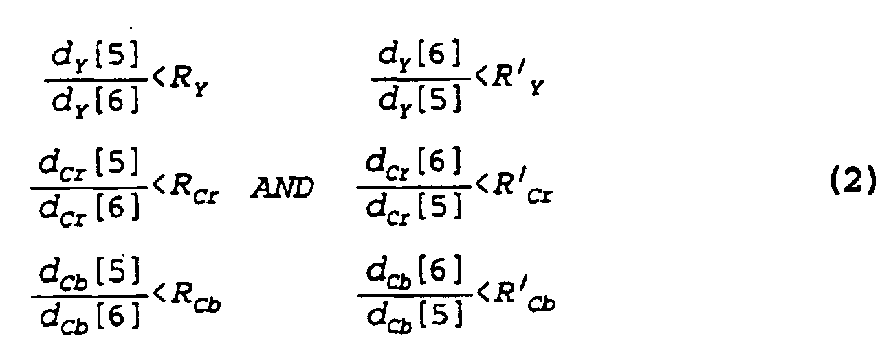
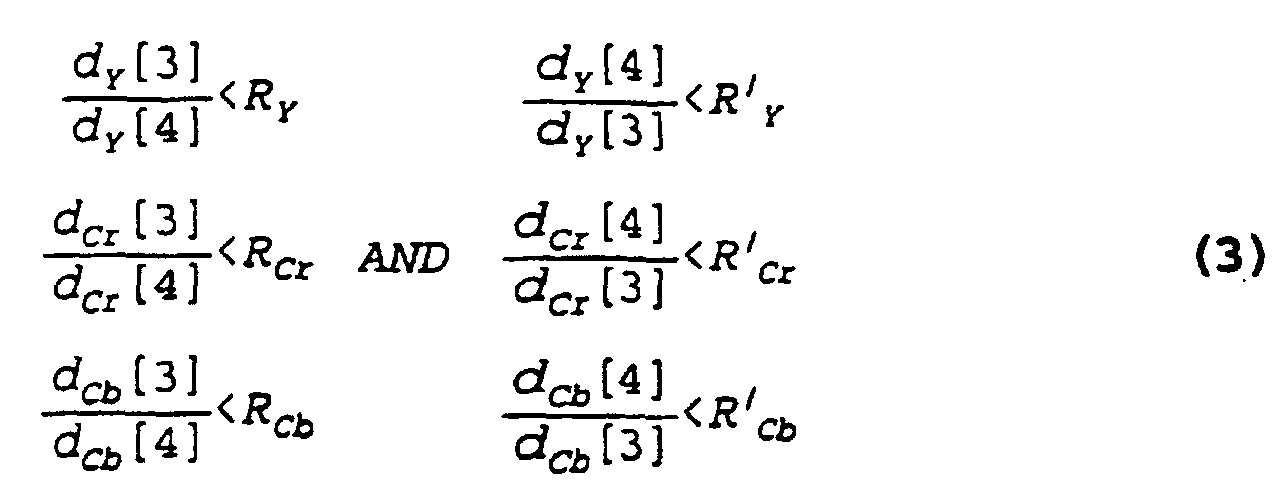 knowledge of the input data. For example, the thresholds may be set by user input commands or by a set of training data.
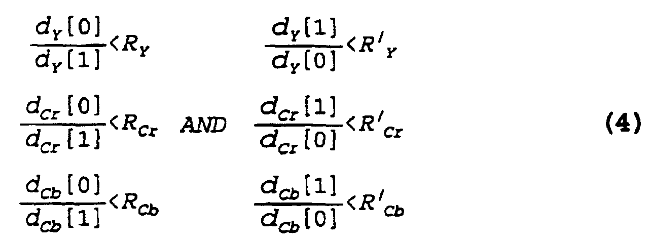
- If all of Eq. (1) - (4) are satisfied; i.e. the film test yields a positive indication of a film condition, then Ψ is set to 1 and the next 10 fields output from the 8
field delay circuit 46 is classified as film. Otherwise, Ψ is set to zero and the next two fields output from the 8field delay circuit 46 is classified as non-film (i.e. video) and the above detection process is repeated for new input data. - The
pulldown detector 50 also generates a two bit mode order value, having values 0-3 (base 10) to indicate to therate controller 14 the reconstruction of the frames, as illustrated in Table 1 below:FILM MODE ORDER VALUE DESCRIPTION 0 FIELD1/ FIELD2 1 FIELD2/ FIELD1 2 FIELD1/FIELD2/ REPEAT FIELD1 3 FIELD2/FIELD1/REPEAT FIELD2 - In a second exemplary embodiment, the
statistics generator 48 passes information to thescene change detector 50 that detects the occurrences of instantaneous changes in the scenes, or "cuts", in the input video. The sum of absolute differences between pixels in the current and two-field delayed fields is used to categorize the amount of change between fields. In the typical scene, this parameter is normally small and varies slowly over several frames, even in scenes with apparently unpredictable motion. A scene may therefore be determined to be continuous if all field differences are below a predetermined threshold, TLOW, and vary between successive values by a small amount ΔTLOW. - At a cut between scenes, however, this parameter becomes relatively large since the two fields that are used to calculate the field differences occur in different scenes. In this case, the field differences are normally larger than a predetermined threshold THIGH. Furthermore, because the field differences are calculated between alternate fields, upon the occurrence of a scene cut, two consecutive fields have a field difference greater than THIGH.
- The detection of a scene change is therefore determined with high confidence when at least two high field differences are detected which are preceded and succeeded by relatively low field differences. The look-ahead nature of the
statistics generator 48 allows the detection of a number of succeeding field differences to be proceeded in order to improve the reliability of the scene detection. Furthermore, the scene change may be detected one or more frame times before the scene change enters theencoder module 16 to be encoded. This allows theencoder 10 to change encoding parameters prior to the scene change; for example, for reducing the encoding quality of the frames before the scene change, which may not cause a change in video quality visible to the viewer of the decoded video, while improving encoding efficiency of theencoder 10. - Upon detection of these changes, the
scene change detector 52 outputs a scene change flag, which is sent to therate controller 14. For example, a scene change flag may indicate a picture type such as an intra coding setting. For example, for a scene change attaining a specified confidence level of detection, an intra frame flag may be generated and sent to therate controller 14 to intra code the entire frame. Intra frame flags may also be output from thescene change detector 52 as an alternative resynchronization method. Thestatistics generator 48 includes a counter (not shown) for generating a periodic count, and thepreprocessor 12 responds to the periodic count for generating an intra frame flag at regular intervals. In the alternative resynchronization method, thepreprocessor 12 responds to the scene change flag to generate the intra frame flag, and therate controller 14 responds to the intra frame flag for inserting an intra frame into the plurality of frames at a position corresponding to a scene change. In this method, thescene change detector 52 chooses to alter the frequency of intra frames according to the relative position of a scene change to make an intra frame and a scene change coincident, where thepreprocessor 12 responds to the scene change flag to modify the count of the counter and to generate the intra frame flag upon the modification of the count. - Alternatively, the
scene change detector 52 may also output a value, such as an 8-bit value, to therate controller 14 to indicate the probability or "strength" of a scene change. The 8-bit value may also indicate other scene changes such as partial scene changes. - In addition to detecting film, the 3:2
pulldown processor 32 may also insert intra frames at regular intervals to allow for insertion of commercials and I/P frame coding as an alternative to progressive refresh implementations. - In a third exemplary embodiment, the
fade detector 53 determines a video fade in the video data. The presence of a video fade added to a film as well as the fade rate may cause transitions from film to film or film to video to generate a false detection of the film. Thefade detector 53 detects such video transitions from the statistics using the average pixel value as an indication of a relatively large change in brightness of the scene before and after a fade. Thefade detector 53 responds to the average pixel values being less than a predetermined value to generate a fade flag indicating a fade in the video. - In a fourth exemplary embodiment, the video encoder control system adapts the resolution of the encoding in response to changes in scenes as measured by frame statistics. The
statistics generator 48 of the 3:2pulldown processor 32 generates the sums of absolute field differences of pixels of the input video data as a measure of the complexity of the corresponding image. Alternatively, variances of the pixels between fields may be calculated. The sums are sent to therate controller 14 which determines if the sums have exceeded a predetermined value. If the predetermined value is exceeded; i.e. the complexity of the images to be encoded is relatively high, then therate controller 14 generates a resolution select flag to reduce the resolution of the encoded image, as described hereafter. - Referring to FIG. 5, the input video data is processed by the
adaptive prefilter 36 in the exemplary embodiment using a first predetermined bank of 256 sets of filter values or coefficients selected by therate controller 14 using a prefilter select signal at a rate of once every frame. Theadaptive prefilter 36 also receives the film flag from the 3:2pulldown processor 32 which indicates whether the input video data corresponds to progressive film or interlaced video. Theadaptive prefilter 36 uses the film flag to select filter values from a second predetermined bank of sets of filter values. - The film mode flag and the prefilter select signals are processed by an 8 × 8
filter 68 which is a set of 8 horizontal scan line taps and 8 vertical taps to perform 8 × 8 filtering on a frame basis. The taps of the 8 × 8 filter are programmable. For example, the taps on every other row may be set to zero, thus reducing the 8 × 8 filter to an 8 × 4 filter that may be applied to the pixels of a frame to perform field filtering, with only values from one of the two fields per frame are involved in the computation of the corresponding output value of thefilter 68. - When the film flag is off, the
filter 68 operates as an 8 × 4 filter for filtering on a field basis. When the film flag is on, thefilter 68 performs 8 × 8 filtering on a frame basis with the restriction on the taps; i.e. alternate rows of taps being set to zero, is removed. Thus the prefiltering is adaptively performed on a field basis for video material and on a frame basis for film material. - A plurality of filters; i.e. sets of filter values or coefficients, are provided for each type of filtering, such as field basis filtering and frame basis filtering. The plurality of filters are determined by different settings of the taps of the 8 × 8
filter 68. In addition to adapting the filtering on a field or frame basis depending on whether the input video data is film material or video material, thefilter 68 is adaptive by selecting from one of a set of frame filter values or a set of field filter values depending on the difficulty to encode the video data based on the complexity of the video images as well as the state of theencoder 10. The scene complexity may be measured by the sum of the absolute values of the field differences in successive fields of the same parity. - Alternatively, the
filter 68 uses the sums of absolute values of field differences as well as an encoder bit rate set by therate controller 14 to select at least one of the plurality of filter values for filtering the delayed video data. - As some of the predetermined sets of filter values may be negative, possible overflow conditions in the filtering is avoided by clamping or latching the output of the 8 × 8
filter 68 using aclamp 70 to within an 8-bit range of 0 to 256. - Each of the Y, Cb, and Cr values are filtered independently with different sets of filter values in the above described manner.
- In the exemplary embodiment, the
adaptive prefilter 36 outputs clamped data of 720 pixels which are processed by a 2:1horizontal subsampler 38. The 2:1horizontal subsampler 38 responds to the resolution select flag from therate controller 14 to determine the rate of subsampling. In the exemplary embodiment using the MPEG encoding standard, a 704 mode and a 352 mode are supported. If the 704 mode is selected, the 2:1horizontal subsampler 72 is disabled, and the processed video data having 704 pixels per line is input to the 2:1horizontal subsampler 72 and passes through unchanged. If the 352 mode is selected, the Y, Cb, and Cr values are subsampled by a factor of two, with the first pixel of each line remaining, to provide 352 pixels per line of resolution. - In an alternative embodiment, the vertical filter and
subsampler 34 performs adaptive filtering using the film flag in a manner as described above to perform frame or field filtering. The vertical filter andsubsampler 34 thus performs chroma downsampling to convert 4:2:2 chroma to 4:2:0 chroma, depending on whether the video data to be processed is film or video material as determined by the 3:2pulldown processor 32 by the film flag. - It is understood that one skilled in the art may adapt the disclosed resolution control method using video data statistics to other video standards and video encoders encoding different pixels per line resolutions.
- The above resolution control method may also be used in conjunction with the
adaptive prefilter 36 described above to provide a finer control of the resolution. In addition, in employing the statistics to control the resolution as well as the look-ahead capability of theencoder 10 from the delay of the input video data, theencoder 10 may be controlled to prepare for scene changes by increasing the resolution using the resolution select flag and reducing the number of bits allocated to at least one frame prior to the scene change to reduce the generation of artifacts in the encoding process. - In alternative embodiments, the above disclosed resolution control method may be used with other encoding methods to choose an encoding method for the I, P or B frames to provide sufficient resolution.
- As shown in FIG. 6, a method is disclosed for controlling the
video encoder 10, as described above, including the steps of starting the control of thevideo encoder 10 instep 74; receiving input video data instep 76; preprocessing the video data instep 78; and controlling theencoder 10 using the delayed video data and the statistics instep 88. The step of preprocessing includes the steps of delaying the video data by N frames where N > 1, to generate delayed video data instep 80; generating statistics from the input video data instep 82; processing the statistics to generate flags, including scene change flags, film flags, and video fade flags instep 84; and determining resolution settings from the statistics instep 86. - While the disclosed video encoder control system and method has been particularly shown and described with reference to the preferred embodiments, it will be understood by those skilled in the art that various modifications in form and detail may be made therein without departing from the scope of the invention. Accordingly, modifications such as those suggested above, but not limited thereto, are to be considered within the scope of the invention as set out in the appended claims.
Claims (32)
- A video encoder control system including a video encoder (10) including:
a processor (32) including:a multiple field delay circuit (42, 44, 46) for delaying input video data by a predetermined number N frames, N > 1, to generate delayed video data, the input video data corresponding to a first frame of a plurality of frames with each frame associated with corresponding fields each having a parity;a statistics generator (48) for processing the input video data to generate statistics of the first frame and to generate a control signal, the generated statistics including subsampled low pass filter image values, a sum of a plurality of absolute values of field differences, and a maximum value over a field of the plurality of absolute values of field differences between pixel values of the subsampled low pass filter image values; anda first detector (50) for detecting a non-film condition using the maximum value for performing film detection. - The video encoder control system of claim 1 wherein the processor (32) is operatively associated with the video encoder (10) to encode the input video data in accordance with the Motion Picture Experts Group (MPEG) standard.
- The video encoder control system of claim 1 wherein a rate controller (14) receives the control signal associated with the first frame for controlling an encoder module (16) prior to the encoding of the corresponding delayed video data to perform a look-ahead operation for adjusting the encoding thereof.
- The video encoder control system of claim 1 wherein the statistics generator (48) generates averages of blocks of pixels of a field as the subsampled low pass filter image values of the field.
- The video encoder control system of claim 1 wherein the statistics generator (48) calculates the sum of absolute values of field differences between pixels of successive fields having the same parity;the processor (32) includes a second detector (52), using the sum, for determining a threshold condition corresponding to the sum exceeds a predetermined threshold, for detecting a scene change from the first frame and a successive frame in response to the threshold condition, for generating a scene change flag as the control signal; andthe rate controller (14) controls the encoder module (16) using the scene change flag.
- The video encoder control system of claim 1 wherein the statistics generator (48) determines an average pixel value of each field; and
a fade detector (53) for detecting video transitions from the statistics using the average pixel values associated with the first field and successive fields to determine a video fade based on the average pixel values being less than a predetermined value to generate a fade flag indicating a fade in the video. - The video encoder control system of claim 1 wherein the statistics generator (48) determines the sum of absolute values of field differences between pixels of successive fields having the same parity; and
the video encoder control system further includes a resolution selector using the sum for changing the resolution of the encoding of the first frame. - The video encoder control system of claim 7 wherein the resolution selector responds to the sum for generating a resolution select signal;
the processor (32) further includes a sampler (38), responsive to the resolution select signal, for sampling the delayed video data at a resolution corresponding to the resolution select signal. - The video encoder control system of claim 1 wherein the statistics generator (48) generates absolute values of the differences between the low pass filtered image values from the subsampled low pass filtered image values and calculates the sum of absolute values of field differences between pixels of successive fields having the same parity and the maximum absolute differences of the low pass filter image values;the first detector (50) uses the sum for detecting a redundant field as the control signal in the associated fields and for generating a redundancy flag corresponding to the redundant field; andthe rate controller (14) controls the encoder module (16) using the redundancy flag.
- The video encoder control system of claim 9 wherein the first detector (50) performs a 3:2 pulldown detection on the input video data which includes film data.
- The video encoder control system of claim 9 wherein the processor (32) further includes a prefilter (36), responsive to the film flag, for filtering the delayed video data using a plurality of filter values corresponding to the film flag.
- The video encoder control system of claim 11 wherein the prefilter (36) uses the sums of absolute values of field differences and an encoder bit rate to select at least one of the plurality of filter values for filtering the delayed video data:
- The video encoder control system of claim 11 wherein the prefilter (36) includes a video data clamp (70) for clamping the filtered delayed video data within a predetermined range to prevent filter overflow.
- The video encoder control system of claim 9 wherein the first detector (50) uses the maximum values of absolute field differences associated with the first frame and the successive frames to determine a locally changing region as the non-film condition corresponding to the redundancy flag.
- The video encoder control system of claim 14 wherein the processor (32) includes:a second detector (52) for detecting a scene change from the first frame and a successive frame and for generating a scene change flag; anda counter for generating a periodic count, the processor (32) responsive to the periodic count for generating an intra frame flag, the processor (32) responds to the scene change flag to generate the intra frame flag; andthe rate controller (14) responds to the intra frame flag for inserting an intra frame into the plurality of frames at a position corresponding to the scene change.
- The video encoder control system of claim 15 wherein the processor (32) responds to the scene change flag to modify the count of the counter and to generate the intra frame flag upon the modification of the count
- A video encoder for detecting film and scene changes in input video data corresponding to a plurality of frames to be encoded comprising:a multiple field delay circuit (42, 44, 46) for delaying first input video data by a predetermined number N of frames, N > 1, to generate first delayed video data, the first input video data corresponding to a first frame having associated fields each having a parity;a statistics generator (48) including a low pass filter (58, 60) for processing the input video data to generate statistics of the first frame, the generated statistics including subsampled low pass filter image values, sums of a plurality of absolute values of field differences, and a maximum value over a field of the plurality of absolute values of field differences between pixel values of the subsampled low pass filter image values; anda first detector (50) using the statistics for detecting a non-film condition of the first frame from the maximum value, for detecting a scene change condition between the plurality of frames from the sums of absolute values exceeding a predetermined threshold, for detecting a video fade condition between the plurality of frames, and for generating film flags, scene change flags, and video fade flags;an encoding module (16); anda rate controller (14) responsive to the generated film flags, the generated scene change flags, and the generated video fade flags for controlling the encoding module to encode the first delayed video data.
- The video encoder of claim 17 wherein the statistics generator (48) determines the sum of absolute values of field differences between pixels of successive fields having the same parity;the processor (32) includes a resolution selector, responsive to the sum, for generating a resolution select signal; andthe rate controller (14) responds to the resolution select signal to change the resolution of the encoding of the first frame.
- The video encoder of claim 17 further comprising a control module (11) for processing input commands including an expected film command; and
wherein the first detector (50) responds to the expected film command for generating the film flags. - The video encoder of claim 17 wherein the statistics generator (48) calculates the sum of absolute values of field differences between pixels of successive fields having the same parity, and
the first detector (50) uses the sum to detect the scene change condition from the first frame and a successive frame. - The video encoder of claim 20 wherein the statistics generator (48) determines an average pixel value of each field; and
the video encoder (10) includes a second detector (53) which uses the average pixel values associated with the first field and successive fields to determine a video fade condition and to generate a corresponding video fade flag. - The video encoder of claim 17 wherein the statistics generator (48) calculates the sum of absolute values of field differences between pixels of successive fields having the same parity; and
the first detector (50) uses the sum for detecting a redundant field in the associated fields from input film data as the input video data, and for generating one of the film flags corresponding to the redundant field. - The video encoder of claim 22 wherein the multiple field delay circuit (42, 44, 46) delays the input video data by at least one field to generate second delayed video data; and
the statistics generator (48) generates the sum of absolute values of field differences from the input video data and the second delayed video data. - The video encoder of claim 22 wherein the statistics generator (48) determines a maximum value of a plurality of absolute field differences of the subsampled low pass filter image values; and
the first detector (50) uses the maximum values of absolute field differences associated with the first frame and the successive frames to determine a locally changing region as a non-film condition corresponding to the film flag. - A method for controlling a video encoder (10) to encode input video data corresponding to a plurality of frames associated with corresponding fields each having a parity, the method comprising the steps of:delaying the input video data by a predetermined number N of frames, N > 1, as delayed video data;processing the input video data to generate statistics of the first field of the first frame and successive fields, including subsampled low pass filter image values, a sum of a plurality of absolute values of field differences of the subsampled low pass filter image values, and a maximum value over a field of the plurality of absolute values of field differences between pixel values of the subsampled low pass filter image values;detecting for a non-film condition to generate a film flag using the maximum value for film detection;controlling the encoding of the delayed video data corresponding to the first frame by the video encoder (10) using the statistics and the film flag.
- The method of claim 25 including the steps of:detecting a scene change condition between the plurality of fields from the sum of the plurality of absolute values of field differences exceeding a predetermined threshold;generating a scene change flag from the scene change condition; andproviding the scene change flag to a rate controller for performing the step of controlling the encoding.
- The method of claim 25 wherein:generating a resolution select flag from a sum change condition;the step of processing includes the steps of:generating sums of absolute values of field differences between pixels of successive fields having the same parity; anddetecting a change in the sums as the sum change condition to generate the resolution select flag; andthe step of controlling includes the step of changing the resolution of the encoding of the first frame using the resolution select flag.
- The method of claim 25 including the steps of:detecting a non-film condition of at least the first field from the statistics;generating the film flag corresponding to the non-film condition; andproviding the film flag to a rate controller for performing the step of controlling the encoding.
- The method of claim 28 including the steps of:detecting a redundant field in the associated fields from a sum;the step of generating includes generating the film flag corresponding to the redundant field from input film data as the input video data; andthe step of processing includes the step of calculating the sum from absolute field differences between pixels of the first field and successive fields of the same parity as the first field.
- The method of claim 29 wherein further comprising the step of detecting a scene change condition includes the step of detecting a scene change from the first frame and a successive frame using the sum.
- The method of claim 30 wherein the step of processing includes the step of determining a subsampled low pass filter image value of the first field and successive fields; and
the step of detecting includes the steps of:using a maximum value of the absolute field differences of the subsampled low pass filter values of the first field and the successive fields to determine a locally changing region as a non-film condition; andgenerating the film flag upon the maximum value of absolute field differences exceeding a predetermined value. - The method of claim 30 wherein:the step of processing includes the step of determining an average pixel value of each field; andthe step of detecting includes the steps of:using the average pixel values of the first field and the successive fields to determine a video fade; andgenerating a video fade flag upon the average pixel values exceeding a predetermined value.
Applications Claiming Priority (2)
| Application Number | Priority Date | Filing Date | Title |
|---|---|---|---|
| US08/327,530 US5734419A (en) | 1994-10-21 | 1994-10-21 | Method of encoder control |
| US327530 | 1994-10-21 |
Publications (3)
| Publication Number | Publication Date |
|---|---|
| EP0708564A2 EP0708564A2 (en) | 1996-04-24 |
| EP0708564A3 EP0708564A3 (en) | 1997-11-19 |
| EP0708564B1 true EP0708564B1 (en) | 2002-02-13 |
Family
ID=23276916
Family Applications (1)
| Application Number | Title | Priority Date | Filing Date |
|---|---|---|---|
| EP95307225A Expired - Lifetime EP0708564B1 (en) | 1994-10-21 | 1995-10-11 | Method of encoder control |
Country Status (5)
| Country | Link |
|---|---|
| US (1) | US5734419A (en) |
| EP (1) | EP0708564B1 (en) |
| JP (1) | JP3280211B2 (en) |
| CA (1) | CA2157309C (en) |
| DE (1) | DE69525411T2 (en) |
Families Citing this family (53)
| Publication number | Priority date | Publication date | Assignee | Title |
|---|---|---|---|---|
| JP3353604B2 (en) * | 1995-08-09 | 2002-12-03 | ソニー株式会社 | Moving image encoding method and apparatus, and signal recording medium |
| US6075768A (en) | 1995-11-09 | 2000-06-13 | At&T Corporation | Fair bandwidth sharing for video traffic sources using distributed feedback control |
| US5825927A (en) * | 1996-01-16 | 1998-10-20 | Hitachi America, Ltd. | Methods and apparatus for encoding video data in a manner that is well suited for decoding by regular or downconverting decoders |
| GB9607645D0 (en) * | 1996-04-12 | 1996-06-12 | Snell & Wilcox Ltd | Processing of video signals prior to compression |
| GB9611455D0 (en) * | 1996-05-29 | 1996-08-07 | Digi Media Vision Ltd | Method and apparatus for processing a digital signal |
| DE19626108A1 (en) * | 1996-06-28 | 1998-01-08 | Thomson Brandt Gmbh | Digital image signal coding method e.g. for Digital Video Broadcasting |
| TW303555B (en) * | 1996-08-08 | 1997-04-21 | Ind Tech Res Inst | Digital data detecting method |
| US5847772A (en) * | 1996-09-11 | 1998-12-08 | Wells; Aaron | Adaptive filter for video processing applications |
| JPH10145779A (en) * | 1996-11-06 | 1998-05-29 | Sony Corp | Field detection device and field detection method, image encoding device and image encoding method, and recording medium and recording method |
| US6115420A (en) * | 1997-03-14 | 2000-09-05 | Microsoft Corporation | Digital video signal encoder and encoding method |
| FR2764156B1 (en) * | 1997-05-27 | 1999-11-05 | Thomson Broadcast Systems | PRETREATMENT DEVICE FOR MPEG II CODING |
| KR100756596B1 (en) * | 1997-07-08 | 2007-09-10 | 소니 가부시끼 가이샤 | Video data encoder and video data encoding method |
| US6011870A (en) * | 1997-07-18 | 2000-01-04 | Jeng; Fure-Ching | Multiple stage and low-complexity motion estimation for interframe video coding |
| US6084641A (en) * | 1997-08-06 | 2000-07-04 | General Instrument Corporation | Fade detector for digital video |
| US6014182A (en) * | 1997-10-10 | 2000-01-11 | Faroudja Laboratories, Inc. | Film source video detection |
| US6873368B1 (en) | 1997-12-23 | 2005-03-29 | Thomson Licensing Sa. | Low noise encoding and decoding method |
| KR100591211B1 (en) * | 1997-12-23 | 2006-06-19 | 톰슨 라이센싱 | Low noise encoding and decoding method |
| US6100940A (en) * | 1998-01-21 | 2000-08-08 | Sarnoff Corporation | Apparatus and method for using side information to improve a coding system |
| JP2000059792A (en) * | 1998-08-06 | 2000-02-25 | Pioneer Electron Corp | High efficiency encoding device of dynamic image signal |
| BE1012172A5 (en) * | 1998-09-15 | 2000-06-06 | Barco Naanloze Vennootschap | Method and apparatus for video processing. |
| EP1119979B1 (en) * | 1998-09-29 | 2013-01-23 | General Instrument Corporation | Method and apparatus for detecting scene changes and adjusting picture coding type in a high definition television encoder |
| US6731684B1 (en) | 1998-09-29 | 2004-05-04 | General Instrument Corporation | Method and apparatus for detecting scene changes and adjusting picture coding type in a high definition television encoder |
| EP0994626A1 (en) | 1998-10-12 | 2000-04-19 | STMicroelectronics S.r.l. | Detection of a 3:2 pulldown in a motion estimation phase and optimized video compression encoder |
| US6195394B1 (en) * | 1998-11-30 | 2001-02-27 | North Shore Laboratories, Inc. | Processing apparatus for use in reducing visible artifacts in the display of statistically compressed and then decompressed digital motion pictures |
| US6559890B1 (en) * | 1999-04-21 | 2003-05-06 | Ascent Media Group, Inc. | Methods and apparatus for correction of 2-3 field patterns |
| US6625322B1 (en) * | 1999-06-08 | 2003-09-23 | Matsushita Electric Industrial Co., Ltd. | Image coding apparatus |
| GB2357210A (en) * | 1999-12-06 | 2001-06-13 | Snell & Wilcox Ltd | Inserting future bit rate information in a compressed data stream |
| EP1183873A1 (en) * | 2000-02-29 | 2002-03-06 | Koninklijke Philips Electronics N.V. | Film source video detection and encoding |
| WO2003015422A1 (en) * | 2001-07-10 | 2003-02-20 | Sony Corporation | Video signal judgment apparatus and method |
| US6804301B2 (en) | 2001-08-15 | 2004-10-12 | General Instrument Corporation | First pass encoding of I and P-frame complexity for compressed digital video |
| US7027515B2 (en) * | 2002-10-15 | 2006-04-11 | Red Rock Semiconductor Ltd. | Sum-of-absolute-difference checking of macroblock borders for error detection in a corrupted MPEG-4 bitstream |
| US20040090554A1 (en) * | 2002-10-23 | 2004-05-13 | Takahiro Nishi | Picture coding method |
| EP1515298A1 (en) * | 2003-08-21 | 2005-03-16 | VastView Technology Inc. | High-quality image liquid crystal display device with improved response speed and the driving method thereof |
| EP1524856A1 (en) * | 2003-10-15 | 2005-04-20 | Sony International (Europe) GmbH | Method for processing video signals |
| US7352808B2 (en) | 2004-01-29 | 2008-04-01 | International Business Machines Corporation | System and method for the dynamic resolution change for video encoding |
| US7382417B2 (en) * | 2004-12-23 | 2008-06-03 | Intel Corporation | Method and algorithm for detection of scene cuts or similar images in video images |
| EP1681878A1 (en) * | 2005-01-12 | 2006-07-19 | Thomson Licensing | Time base correction for digitized video signal |
| WO2006113057A2 (en) * | 2005-04-15 | 2006-10-26 | Thomson Licensing | Down-sampling and up-sampling processes for chroma samples |
| US7864840B2 (en) | 2005-04-15 | 2011-01-04 | Inlet Technologies, Inc. | Scene-by-scene digital video processing |
| TWI325124B (en) * | 2006-05-10 | 2010-05-21 | Realtek Semiconductor Corp | Motion detection method and related apparatus |
| US8259575B2 (en) * | 2007-10-17 | 2012-09-04 | Samsung Techwin Co., Ltd. | Internet network apparatus and method of transferring data using the same |
| US8270483B1 (en) * | 2008-01-18 | 2012-09-18 | Maxim Integrated Products, Inc. | Method and apparatus for applying accurate parameter estimation and efficient fade detection in weighted prediction for video compression |
| US8571106B2 (en) * | 2008-05-22 | 2013-10-29 | Microsoft Corporation | Digital video compression acceleration based on motion vectors produced by cameras |
| GB0905317D0 (en) * | 2008-07-14 | 2009-05-13 | Musion Ip Ltd | Video processing and telepresence system and method |
| FR2963189B1 (en) * | 2010-07-20 | 2013-06-21 | Freebox | METHOD FOR ADAPTIVE ENCODING OF A DIGITAL VIDEO STREAM, IN PARTICULAR FOR XDSL LINE BROADCAST. |
| TW201345262A (en) * | 2012-04-20 | 2013-11-01 | Novatek Microelectronics Corp | Image processing circuit and image processing method |
| US8855214B2 (en) * | 2013-02-04 | 2014-10-07 | Faroudja Enterprises, Inc. | Multidimensional video processing |
| KR102136848B1 (en) * | 2013-07-15 | 2020-07-22 | 삼성전자 주식회사 | Image Processing Device, Image Processing System and Image Processing Method |
| US9591254B2 (en) | 2015-03-26 | 2017-03-07 | Qualcomm Incorporated | Device and method for processing video data |
| US10412412B1 (en) * | 2016-09-30 | 2019-09-10 | Amazon Technologies, Inc. | Using reference-only decoding of non-viewed sections of a projected video |
| US10553029B1 (en) | 2016-09-30 | 2020-02-04 | Amazon Technologies, Inc. | Using reference-only decoding of non-viewed sections of a projected video |
| US10609356B1 (en) | 2017-01-23 | 2020-03-31 | Amazon Technologies, Inc. | Using a temporal enhancement layer to encode and decode stereoscopic video content |
| US12088821B1 (en) * | 2020-06-30 | 2024-09-10 | Amazon Technologies, Inc. | Dynamic encoder-time scaling service for live and on-demand adaptive streaming |
Family Cites Families (42)
| Publication number | Priority date | Publication date | Assignee | Title |
|---|---|---|---|---|
| GB2167583B (en) * | 1984-11-23 | 1988-11-02 | Nat Res Dev | Apparatus and methods for processing an array of items of data |
| GB2193069B (en) * | 1986-07-17 | 1990-08-29 | Toshiba Kk | Image frame composing circuit utilizing color look-up table |
| JP2639412B2 (en) * | 1987-06-01 | 1997-08-13 | 株式会社鷹山 | Image processing method |
| US5128658A (en) * | 1988-06-27 | 1992-07-07 | Digital Equipment Corporation | Pixel data formatting |
| US5155588A (en) * | 1990-02-06 | 1992-10-13 | Levien Raphael L | Color correction and apparatus for photographic reproduction |
| US5040062A (en) * | 1990-03-19 | 1991-08-13 | At&T Bell Laboratories | Television signal arrangement where selected signals are encoded digitally |
| US5043808A (en) * | 1990-03-19 | 1991-08-27 | At&T Bell Laboratories | High definition television arrangement employing motion compensated prediction error signals |
| US5204664A (en) * | 1990-05-16 | 1993-04-20 | Sanyo Electric Co., Ltd. | Display apparatus having a look-up table for converting pixel data to color data |
| CA2044558C (en) * | 1990-07-09 | 1995-06-13 | David M. Smith | Methods and apparatus for cymk-rgb ramdac |
| US5276798A (en) * | 1990-09-14 | 1994-01-04 | Hughes Aircraft Company | Multifunction high performance graphics rendering processor |
| US5140414A (en) * | 1990-10-11 | 1992-08-18 | Mowry Craig P | Video system for producing video images simulating images derived from motion picture film |
| US5134477A (en) * | 1990-12-11 | 1992-07-28 | At&T Bell Laboratories | Hdtv receiver |
| US5134475A (en) * | 1990-12-11 | 1992-07-28 | At&T Bell Laboratories | Adaptive leak hdtv encoder |
| US5144423A (en) * | 1990-12-11 | 1992-09-01 | At&T Bell Laboratories | Hdtv encoder with forward estimation and constant rate motion vectors |
| US5136377A (en) * | 1990-12-11 | 1992-08-04 | At&T Bell Laboratories | Adaptive non-linear quantizer |
| US5128756A (en) * | 1990-12-11 | 1992-07-07 | At&T Bell Laboratories | High definition television coding arrangement with graceful degradation |
| US5260787A (en) * | 1991-05-14 | 1993-11-09 | Sony Electronics Inc. | Film-to-video frame image conversion apparatus and method for selectively identifying video fields and frames |
| US5170251A (en) * | 1991-05-16 | 1992-12-08 | Sony Corporation Of America | Method and apparatus for storing high definition video data for interlace or progressive access |
| JP3189861B2 (en) * | 1992-11-13 | 2001-07-16 | ソニー株式会社 | Video encoding apparatus and method |
| US5196924A (en) * | 1991-07-22 | 1993-03-23 | International Business Machines, Corporation | Look-up table based gamma and inverse gamma correction for high-resolution frame buffers |
| US5267035A (en) * | 1991-08-08 | 1993-11-30 | Samsung Electronics Co., Ltd. | Motion detection for video including that obtained from film |
| US5243419A (en) * | 1991-10-31 | 1993-09-07 | At&T Bell Laboratories | Soft coding for HDTV |
| US5214507A (en) * | 1991-11-08 | 1993-05-25 | At&T Bell Laboratories | Video signal quantization for an mpeg like coding environment |
| US5231484A (en) * | 1991-11-08 | 1993-07-27 | International Business Machines Corporation | Motion video compression system with adaptive bit allocation and quantization |
| US5245436A (en) * | 1992-02-14 | 1993-09-14 | Intel Corporation | Method and apparatus for detecting fades in digital video sequences |
| US5247363A (en) * | 1992-03-02 | 1993-09-21 | Rca Thomson Licensing Corporation | Error concealment apparatus for hdtv receivers |
| US5262855A (en) * | 1992-03-25 | 1993-11-16 | Intel Corporation | Method and apparatus for encoding selected images at lower resolution |
| US5293229A (en) * | 1992-03-27 | 1994-03-08 | Matsushita Electric Corporation Of America | Apparatus and method for processing groups of fields in a video data compression system |
| JPH05328317A (en) * | 1992-05-25 | 1993-12-10 | Toshiba Corp | Video signal transmitter-receiver |
| JP2611607B2 (en) * | 1992-06-29 | 1997-05-21 | 日本ビクター株式会社 | Scene change detection device |
| US5270813A (en) * | 1992-07-02 | 1993-12-14 | At&T Bell Laboratories | Spatially scalable video coding facilitating the derivation of variable-resolution images |
| US5253056A (en) * | 1992-07-02 | 1993-10-12 | At&T Bell Laboratories | Spatial/frequency hybrid video coding facilitating the derivatives of variable-resolution images |
| US5294974A (en) * | 1992-07-24 | 1994-03-15 | Matsushita Electric Corporation Of America | High-definition video encoding system having color-sensitive quantization |
| US5305102A (en) * | 1992-07-27 | 1994-04-19 | At&T Bell Laboratories | HDTV receiver |
| US5278647A (en) * | 1992-08-05 | 1994-01-11 | At&T Bell Laboratories | Video decoder using adaptive macroblock leak signals |
| US5317398A (en) * | 1992-08-17 | 1994-05-31 | Rca Thomson Licensing Corporation | Video/film-mode (3:2 pulldown) detector using patterns of two-field differences |
| JP3315766B2 (en) * | 1992-09-07 | 2002-08-19 | 富士通株式会社 | Image data encoding method, image data encoding device using the method, image data restoring method, image data restoring device using the method, scene change detecting method, scene change detecting device using the method, scene change recording Device and image data scene change recording / reproducing device |
| JP3443880B2 (en) * | 1992-09-18 | 2003-09-08 | ソニー株式会社 | Video signal encoding method and decoding method |
| US5325125A (en) * | 1992-09-24 | 1994-06-28 | Matsushita Electric Corporation Of America | Intra-frame filter for video compression systems |
| US5329317A (en) * | 1992-09-30 | 1994-07-12 | Matsushita Electric Corporation Of America | Adaptive field/frame filter for interlaced video signals |
| US5491516A (en) * | 1993-01-14 | 1996-02-13 | Rca Thomson Licensing Corporation | Field elimination apparatus for a video compression/decompression system |
| KR0134325B1 (en) * | 1993-12-16 | 1998-04-23 | 배순훈 | Image data preprocessing filter |
-
1994
- 1994-10-21 US US08/327,530 patent/US5734419A/en not_active Expired - Lifetime
-
1995
- 1995-08-31 CA CA002157309A patent/CA2157309C/en not_active Expired - Fee Related
- 1995-10-11 DE DE69525411T patent/DE69525411T2/en not_active Expired - Lifetime
- 1995-10-11 EP EP95307225A patent/EP0708564B1/en not_active Expired - Lifetime
- 1995-10-18 JP JP29383595A patent/JP3280211B2/en not_active Expired - Lifetime
Also Published As
| Publication number | Publication date |
|---|---|
| DE69525411T2 (en) | 2002-10-02 |
| EP0708564A3 (en) | 1997-11-19 |
| JP3280211B2 (en) | 2002-04-30 |
| US5734419A (en) | 1998-03-31 |
| CA2157309C (en) | 1999-10-26 |
| CA2157309A1 (en) | 1996-04-22 |
| JPH08214305A (en) | 1996-08-20 |
| EP0708564A2 (en) | 1996-04-24 |
| DE69525411D1 (en) | 2002-03-21 |
Similar Documents
| Publication | Publication Date | Title |
|---|---|---|
| EP0708564B1 (en) | Method of encoder control | |
| US7177358B2 (en) | Picture coding apparatus, and picture coding method | |
| US6037986A (en) | Video preprocessing method and apparatus with selective filtering based on motion detection | |
| US7039108B2 (en) | Method and device for coding and decoding image sequences | |
| EP0449555B1 (en) | Image encoding apparatus | |
| US6181382B1 (en) | HDTV up converter | |
| US6222881B1 (en) | Using numbers of non-zero quantized transform signals and signal differences to determine when to encode video signals using inter-frame or intra-frame encoding | |
| JP3942630B2 (en) | Channel buffer management in video decoder | |
| US8879635B2 (en) | Methods and device for data alignment with time domain boundary | |
| US5847772A (en) | Adaptive filter for video processing applications | |
| US20050249282A1 (en) | Film-mode detection in video sequences | |
| US6587509B1 (en) | Reducing undesirable effects of an emphasis processing operation performed on a moving image by adding a noise signal to a decoded uncompressed signal | |
| EP1119979B1 (en) | Method and apparatus for detecting scene changes and adjusting picture coding type in a high definition television encoder | |
| EP1711019A2 (en) | Motion compensated temporal filtering for noise reduction pre-processing of digital video data | |
| US20030031255A1 (en) | Video coding method and corresponding video coder | |
| US5589884A (en) | Adaptive quantization controlled by scene change detection | |
| US20020097335A1 (en) | Video data processing device and video data processing method | |
| US20010036230A1 (en) | Variable picture rate coding/decoding method and apparatus | |
| US6798835B2 (en) | Apparatus and method of switching moving-picture bitstream | |
| US6480544B1 (en) | Encoding apparatus and encoding method | |
| EP1418754B1 (en) | Progressive conversion of interlaced video based on coded bitstream analysis | |
| JP2661465B2 (en) | Video encoding device | |
| JP2629409B2 (en) | Motion compensated prediction interframe coding device | |
| JPH07154825A (en) | Image transmission equipment | |
| JPH1056646A (en) | Video signal decoding device |
Legal Events
| Date | Code | Title | Description |
|---|---|---|---|
| PUAI | Public reference made under article 153(3) epc to a published international application that has entered the european phase |
Free format text: ORIGINAL CODE: 0009012 |
|
| AK | Designated contracting states |
Kind code of ref document: A2 Designated state(s): DE FR GB |
|
| PUAL | Search report despatched |
Free format text: ORIGINAL CODE: 0009013 |
|
| AK | Designated contracting states |
Kind code of ref document: A3 Designated state(s): DE FR GB |
|
| 17P | Request for examination filed |
Effective date: 19980508 |
|
| 17Q | First examination report despatched |
Effective date: 20000324 |
|
| GRAG | Despatch of communication of intention to grant |
Free format text: ORIGINAL CODE: EPIDOS AGRA |
|
| GRAG | Despatch of communication of intention to grant |
Free format text: ORIGINAL CODE: EPIDOS AGRA |
|
| GRAH | Despatch of communication of intention to grant a patent |
Free format text: ORIGINAL CODE: EPIDOS IGRA |
|
| GRAH | Despatch of communication of intention to grant a patent |
Free format text: ORIGINAL CODE: EPIDOS IGRA |
|
| GRAA | (expected) grant |
Free format text: ORIGINAL CODE: 0009210 |
|
| REG | Reference to a national code |
Ref country code: GB Ref legal event code: IF02 |
|
| AK | Designated contracting states |
Kind code of ref document: B1 Designated state(s): DE FR GB |
|
| REF | Corresponds to: |
Ref document number: 69525411 Country of ref document: DE Date of ref document: 20020321 |
|
| ET | Fr: translation filed | ||
| PLBE | No opposition filed within time limit |
Free format text: ORIGINAL CODE: 0009261 |
|
| STAA | Information on the status of an ep patent application or granted ep patent |
Free format text: STATUS: NO OPPOSITION FILED WITHIN TIME LIMIT |
|
| 26N | No opposition filed |
Effective date: 20021114 |
|
| REG | Reference to a national code |
Ref country code: FR Ref legal event code: TP Owner name: ALCATEL-LUCENT USA INC., US Effective date: 20130823 Ref country code: FR Ref legal event code: CD Owner name: ALCATEL-LUCENT USA INC., US Effective date: 20130823 |
|
| REG | Reference to a national code |
Ref country code: GB Ref legal event code: 732E Free format text: REGISTERED BETWEEN 20140102 AND 20140108 |
|
| PGFP | Annual fee paid to national office [announced via postgrant information from national office to epo] |
Ref country code: DE Payment date: 20131021 Year of fee payment: 19 Ref country code: FR Payment date: 20131022 Year of fee payment: 19 Ref country code: GB Payment date: 20131021 Year of fee payment: 19 |
|
| REG | Reference to a national code |
Ref country code: GB Ref legal event code: 732E Free format text: REGISTERED BETWEEN 20140109 AND 20140115 |
|
| REG | Reference to a national code |
Ref country code: FR Ref legal event code: GC Effective date: 20140410 |
|
| REG | Reference to a national code |
Ref country code: FR Ref legal event code: RG Effective date: 20141015 |
|
| REG | Reference to a national code |
Ref country code: DE Ref legal event code: R119 Ref document number: 69525411 Country of ref document: DE |
|
| GBPC | Gb: european patent ceased through non-payment of renewal fee |
Effective date: 20141011 |
|
| PG25 | Lapsed in a contracting state [announced via postgrant information from national office to epo] |
Ref country code: DE Free format text: LAPSE BECAUSE OF NON-PAYMENT OF DUE FEES Effective date: 20150501 Ref country code: GB Free format text: LAPSE BECAUSE OF NON-PAYMENT OF DUE FEES Effective date: 20141011 |
|
| REG | Reference to a national code |
Ref country code: FR Ref legal event code: ST Effective date: 20150630 |
|
| PG25 | Lapsed in a contracting state [announced via postgrant information from national office to epo] |
Ref country code: FR Free format text: LAPSE BECAUSE OF NON-PAYMENT OF DUE FEES Effective date: 20141031 |