EP0708502A2 - Multi-row connector comprising flexible contact sheets with insulating resilient pieces - Google Patents
Multi-row connector comprising flexible contact sheets with insulating resilient pieces Download PDFInfo
- Publication number
- EP0708502A2 EP0708502A2 EP95116688A EP95116688A EP0708502A2 EP 0708502 A2 EP0708502 A2 EP 0708502A2 EP 95116688 A EP95116688 A EP 95116688A EP 95116688 A EP95116688 A EP 95116688A EP 0708502 A2 EP0708502 A2 EP 0708502A2
- Authority
- EP
- European Patent Office
- Prior art keywords
- sheet
- contact
- flexible
- circuit board
- receiving
- Prior art date
- Legal status (The legal status is an assumption and is not a legal conclusion. Google has not performed a legal analysis and makes no representation as to the accuracy of the status listed.)
- Granted
Links
Images


Classifications
-
- H—ELECTRICITY
- H01—ELECTRIC ELEMENTS
- H01R—ELECTRICALLY-CONDUCTIVE CONNECTIONS; STRUCTURAL ASSOCIATIONS OF A PLURALITY OF MUTUALLY-INSULATED ELECTRICAL CONNECTING ELEMENTS; COUPLING DEVICES; CURRENT COLLECTORS
- H01R12/00—Structural associations of a plurality of mutually-insulated electrical connecting elements, specially adapted for printed circuits, e.g. printed circuit boards [PCB], flat or ribbon cables, or like generally planar structures, e.g. terminal strips, terminal blocks; Coupling devices specially adapted for printed circuits, flat or ribbon cables, or like generally planar structures; Terminals specially adapted for contact with, or insertion into, printed circuits, flat or ribbon cables, or like generally planar structures
- H01R12/70—Coupling devices
- H01R12/71—Coupling devices for rigid printing circuits or like structures
- H01R12/712—Coupling devices for rigid printing circuits or like structures co-operating with the surface of the printed circuit or with a coupling device exclusively provided on the surface of the printed circuit
- H01R12/716—Coupling device provided on the PCB
-
- H—ELECTRICITY
- H01—ELECTRIC ELEMENTS
- H01R—ELECTRICALLY-CONDUCTIVE CONNECTIONS; STRUCTURAL ASSOCIATIONS OF A PLURALITY OF MUTUALLY-INSULATED ELECTRICAL CONNECTING ELEMENTS; COUPLING DEVICES; CURRENT COLLECTORS
- H01R12/00—Structural associations of a plurality of mutually-insulated electrical connecting elements, specially adapted for printed circuits, e.g. printed circuit boards [PCB], flat or ribbon cables, or like generally planar structures, e.g. terminal strips, terminal blocks; Coupling devices specially adapted for printed circuits, flat or ribbon cables, or like generally planar structures; Terminals specially adapted for contact with, or insertion into, printed circuits, flat or ribbon cables, or like generally planar structures
- H01R12/70—Coupling devices
- H01R12/77—Coupling devices for flexible printed circuits, flat or ribbon cables or like structures
- H01R12/79—Coupling devices for flexible printed circuits, flat or ribbon cables or like structures connecting to rigid printed circuits or like structures
-
- H—ELECTRICITY
- H01—ELECTRIC ELEMENTS
- H01R—ELECTRICALLY-CONDUCTIVE CONNECTIONS; STRUCTURAL ASSOCIATIONS OF A PLURALITY OF MUTUALLY-INSULATED ELECTRICAL CONNECTING ELEMENTS; COUPLING DEVICES; CURRENT COLLECTORS
- H01R12/00—Structural associations of a plurality of mutually-insulated electrical connecting elements, specially adapted for printed circuits, e.g. printed circuit boards [PCB], flat or ribbon cables, or like generally planar structures, e.g. terminal strips, terminal blocks; Coupling devices specially adapted for printed circuits, flat or ribbon cables, or like generally planar structures; Terminals specially adapted for contact with, or insertion into, printed circuits, flat or ribbon cables, or like generally planar structures
- H01R12/70—Coupling devices
- H01R12/82—Coupling devices connected with low or zero insertion force
- H01R12/85—Coupling devices connected with low or zero insertion force contact pressure producing means, contacts activated after insertion of printed circuits or like structures
- H01R12/88—Coupling devices connected with low or zero insertion force contact pressure producing means, contacts activated after insertion of printed circuits or like structures acting manually by rotating or pivoting connector housing parts
Definitions
- This invention relates to an electrical connector for electrically connecting a flexible printed circuit board to a connecting object, such as an FPC (flexible printed circuit) connector, which is of a ZIF (zero insertion force) type and is for connection with a minimal operating force.
- FPC flexible printed circuit
- Japanese patent publication (B2) No. 11,105 of 1982 discloses a connector for electrically connecting a flexible printed circuit board to another printed circuit.
- the flexible printed circuit board comprises a flexible insulator sheet with front and rear surfaces and a sheet end and a conductor pattern extending on said front surface to said sheet end.
- a rigid insulator plate is bonded onto the rear surface of the flexible printed circuit for reinforcing the flexible board.
- a connecter member is mounted on the circuit board.
- the connector member has an elastic contact having a terminal portion which is electrically connected to the circuit board.
- the connecting member has an connector insulator having a contact hole in which the elastic contact is supported to elastically project a contact portion thereof.
- the flexible printed circuit board In order to establish connection of the conductor pattern with the contact, the flexible printed circuit board is inserted together with the rigid insulator plate into the contact hole against a pressing force due to the elasticity of the elastic contact. Therefore, the connector is not a ZIF type.
- the conductor pattern is disadvantageously damaged by friction with the contact during connecting operation. Accordingly, the flexible printed circuit results in a decreased life time.
- the paired connector comprises contact rows of a plurality of contacts in each contact row.
- the multi-row connector comprises a first insulator block having a sheet receiving hole.
- a pair of flexible contact sheets has individual front surfaces and individual sheet ends. On each front surface, rows of parallel conductor patterns are arranged to reach the sheet ends and are not less in number than the contacts in each contact row of a paired or mating connector.
- the flexible contact sheets are received in the sheet receiving hole in a back to back opposing relation.
- a second insulator block has a sheet receiving groove for receiving the flexible contact sheets with the sheet ends protruded through the sheet receiving groove.
- An actuating member is for actuating the flexible contact sheets to bring the parallel conductor patterns near to the contacts of the paired connector after the second insulator block is brought into contact with the paired connector to place the parallel patterns near to the contacts at the sheet ends.
- the multi-row connector is further for connection to a daughter board having a pair of board surfaces and a shim end having a predetermined thickness between the board surfaces.
- a plurality of conductive patterns are formed on the board surfaces in correspondence to the conductor patterns of the flexible contact sheets.
- an electrical connector for electrically connecting a flexible printed circuit board to a connecting object, the flexible printed circuit board comprising a flexible insulator sheet with front and rear surfaces and a sheet end and a conductor pattern extending on the front surface to the sheet end.
- the electrical connector comprises: an insulating resilient piece having an end portion and an extension portion extending from the end portion in a different direction from the end portion, the insulating resilient piece being attached to the rear surface of the flexible printed circuit board so that the end portion is arranged to the sheet end of the flexible printed circuit board and the extension portion extending away from the rear surface of the flexible printed circuit board; a connecting member for being electrically and mechanically connected to the connecting object, the connecting object comprising an insulator block and a contact supported in the insulator block, the contact having a terminal end connected to the connecting object and a contact portion, the connecting member having a receiving hole for loosely receiving the end portion of the insulating resilient piece and the sheet end of the flexible printed circuit board together, the contact portion exposed in the receiving hole; and an actuating member for pressing the extension portion of the insulating resilient piece towards the rear surface of the flexible printed circuit board when the end portion of the insulating resilient piece and the sheet end of the flexible printed circuit board are received together in the receiving hole, whereby the conductor pattern of the
- a multi-row connector for establishing electric connection to a paired connector comprising contact rows of a plurality of contacts in each contact row
- the multi-row connector comprising: a first insulator block having a sheet receiving hole; a pair of flexible contact sheets having individual front surfaces and individual sheet ends with rows of parallel conductor patterns, not less in number than the contacts in each contact row, arranged on each of the front surfaces to reach the sheet ends and with the flexible contact sheets received in the sheet receiving hole in a back to back opposing relation; a second insulator block having a sheet receiving groove for receiving the flexible contact sheets with the sheet ends protruded through the contact receiving groove; and an actuating member for actuating the flexible contact sheets to bring the parallel conductor patterns at the sheet ends near to the contacts after the second insulator block is brought into contact with the paired connector to place the parallel patterns near at the sheet ends to the contacts.
- the multi-row connector comprises: a pair of insulating resilient pieces having individual piece ends fixed to the sheet ends, respectively, and extended backwardly of the flexible contact sheet to have individual free ends spaced apart by a predetermined distance and to be placed in the sheet receiving groove; the actuating member having a first and a second diameter smaller than and greater than the predetermined distance, respectively, so as to be freely inserted between the free ends and to push the free ends apart when the actuating member is inserted between the free ends to be subsequently positioned between the free ends with the first and the second diameters directed substantially perpendicularly and parallel to the predetermined distance, respectively.
- a multi-connector 11 using, as a plurality of flexible contact sheets, a plurality of flexible printed circuit boards having a plurality of conductive patterns according to a first embodiment of this invention.
- the multi-row connector 11 is for establishing electric connection to a printed circuit board 13 or a paired or mating connector 15 used as a mother board.
- the paired connector 15 comprises an insulator block 16 and contact rows of a plurality of contacts 17 supported in the insulator block 16. Each of the contacts 17 has a contact portion and a terminal end connected to the circuit board as shown in Figs. 2 and 3.
- the multi-row connector 11 comprises a first insulator block 19 having two sheet receiving slits 21 collectively as a sheet receiving hole.
- a pair of insulating flexible contact sheets 23 has individual front surfaces depicted in Fig. 1, one as seen and the other opposite to a direction of sight, and individual sheet ends depicted at bottom of the flexible contact sheets 23. It is possible as will be understood from the following to use a single flat flexible sheet as the flexible contact sheet 23.
- Rows of parallel conductor patterns 25 are arranged to reach the sheet ends on each of the front surfaces.
- the conductor patterns 25 are not less in number on each front surface than the contacts 17 in each contact row so that the contacts 17 of the contact rows may be brought into electric contact with the conductor patterns 25.
- the flexible contact sheets 23 are put in the sheet receiving hole 21 in a back to back opposing relation, as is clear in Fig. 1, with the sheet ends brought onto a common plane.
- a second insulator block 27 has a sheet receiving groove 29 for receiving the flexible contact sheets 23 with their sheet ends protruded through the contact receiving groove 29. More specifically, the contact receiving groove 29 has a bottom end which is in contact in Fig. 3 with the paired connector 15.
- An actuating member 31 is for actuating the flexible contact sheets 23 to bring the parallel conductor patterns 25 at the sheet ends near to the contacts 17 after the second insulator block 27 is brought into contact with the paired connector 15 to place the conductor patterns 25 near at the sheet ends to the contacts 17.
- the multi-row connector 11 comprises a pair of insulating resilient pieces 33 having individual piece ends fixed to the sheet ends of the flexible contact sheet 23, respectively, and extended backwardly of the flexible contact sheet 23 to have individual free ends or extension portions extending away from the rear surfaces to be spaced apart by a predetermined distance and to be placed in the sheet receiving groove 29.
- the actuating member 31 has a first and a second diameter smaller and greater than the predetermined distance so as to be freely inserted between the free ends and to push the free ends apart when the actuating member 31 is inserted between the free ends to be subsequently positioned between the free ends with the first and the second diameters directed substantially perpendicular and parallel to the predetermined distance.
- the first and the second insulator blocks 19 and 27 have side surfaces parallel to a direction of the opposing relation of the flexible contact sheets 23, namely, to a sheet of Fig. 2 or 3.
- the first and the second insulator blocks 19 and 27 have a member receiving hole 35 larger than a greater one of the first and the second diameters.
- the actuating member 31 is turned so that the first and the second diameters are directed substantially perpendicular and parallel (Fig. 3) to the predetermined distance. In this manner, the actuating member 31 serves as an operating cam for insertion through the member receiving hole 35.
- the paired connector 15 further has a receiving holes 18 for loosely receiving the sheet end of the flexible contact sheets 23 and the end portions of the insulating resilient pieces 33 together, the contact portions of the contacts 17 are exposed in the receiving holes 18.
- each of contacts 17 is provided with each of the receiving holes 18.
- the force F1 becomes a minimal operating force by the use of the operating cam.
- the multi-row connector 11 further comprise a cover member 37 for covering and receiving the first insulator block 19 on its top.
- the cover member 37 has an insertion portion 39 protruding in the sheet receiving hole 21 to serve as the actuating member 31 when inserted between the free ends.
- the actuating meter 31 of Figs. 1 through 3 is no more separately necessary.
- This multi-row connector 11-1 is for further connection to a daughter board 41 having a pair of board surfaces of a predetermined thickness between the board surfaces.
- the daughter board 41 has a shim end 43 of the predetermined thickness downwardly in Figs. 6 through 9.
- the predetermined thickness is not smaller than the predetermined distance.
- a plurality of conductive patterns 45 are formed on the board surfaces in correspondence to the conductor patterns 25. It is unnecessary that the conductive patterns 45 should reach a bottom end of the shim end 43.
- the first insulator block is divided into first primary and secondary insulator blocks 19-1 and 19-2 having a pair of sheet receiving holes 21-1 and 21-2 collectively as the sheet receiving hole mentioned in connection with Figs. 1 through 3 for individually receiving the flexible contact sheets 23.
- the shim end 43 serves as the actuating member 31.
- the flexible contact sheets are now two separate flexible contact sheets 23-1 and 23-2 having tip ends, respectively. When pushed between the flexible contact sheets 23-1 and 23-2 downwardly of Figs. 6 through 9, the daughter board 41 tucks the flexible contact sheets 23-1 and 23-2 with the conductor patterns 25 brought into contact with the conductive patterns 45 since the flexible contact sheets 23-1 and 23-2 are easily bent to the the board surfaces.
- the shim end 43 comprises an engaging edge portion having flanges 47 forwardly and backwardly protruded from the board surfaces, respectively, for engaging with the first insulator block 19 as best shown in Fig. 9.
- the first insulator block 19 has a shim end receiving opening between the first primary and the secondary insulator blocks 19-1 and 19-2. When the shim end 43 is put between the free ends, the flanges 47 abut the first insulator block 19.
- the second insulator block 27-1 has a pinhead receiving holes 49.
- the daughter board 41 has a pinbody receiving hole 51 for alignment with the pinhead receiving hole 49.
- An insertion pin 53 is inserted in the pinhead and the pinbody receiving boles 49 and 51 after the shim end 43 is put in the shim end receiving opening to bring the pinhead and the pinbody receiving holes 49 and 51 in alignment.
- the pin 53 is for preventing the first insulator block 19 from being inadvertently separated from the second insulator block 27.
- an insulating resilient piece 33-1 may be divided into left and right resilient pieces 55-1 and 55-2 and a framework 57 if the free ends of the flexible contact sheets 23-1 and 23-2 are not stable in the sheet receiving groove 29 or 29-1.
- the resilient pieces 55-1 and 55-2 are enclosed by the framework 57.
- Use of the frame work 57 increases mechanical strength of the insulating resilient pieces 33 described in conjunction with Figs. 1 through 3.
- this invention is described as regards a multi-row connector.
- the present invention can be applied for establishing an electrical connection between a flexible printed circuit board having a single or a plurality Of conductor patterns and a connecting object such as a printed circuit board.
Landscapes
- Coupling Device And Connection With Printed Circuit (AREA)
Abstract
Description
- This invention relates to an electrical connector for electrically connecting a flexible printed circuit board to a connecting object, such as an FPC (flexible printed circuit) connector, which is of a ZIF (zero insertion force) type and is for connection with a minimal operating force.
- Japanese patent publication (B2) No. 11,105 of 1982 discloses a connector for electrically connecting a flexible printed circuit board to another printed circuit. The flexible printed circuit board comprises a flexible insulator sheet with front and rear surfaces and a sheet end and a conductor pattern extending on said front surface to said sheet end. A rigid insulator plate is bonded onto the rear surface of the flexible printed circuit for reinforcing the flexible board. A connecter member is mounted on the circuit board. The connector member has an elastic contact having a terminal portion which is electrically connected to the circuit board. The connecting member has an connector insulator having a contact hole in which the elastic contact is supported to elastically project a contact portion thereof. In order to establish connection of the conductor pattern with the contact, the flexible printed circuit board is inserted together with the rigid insulator plate into the contact hole against a pressing force due to the elasticity of the elastic contact. Therefore, the connector is not a ZIF type. The conductor pattern is disadvantageously damaged by friction with the contact during connecting operation. Accordingly, the flexible printed circuit results in a decreased life time.
- There are known in the prior art various multi-row connectors using the flexible printed circuit boards having a plurality of conductor patterns as contact sheets. Examples are disclosed in United States Patent No. 4,881,908, in United States Patent No. 4,892,487, and in United States Patent No. 5,102,342.
- It is possible in these prior documents to understand that the paired connector comprises contact rows of a plurality of contacts in each contact row. The multi-row connector comprises a first insulator block having a sheet receiving hole. A pair of flexible contact sheets has individual front surfaces and individual sheet ends. On each front surface, rows of parallel conductor patterns are arranged to reach the sheet ends and are not less in number than the contacts in each contact row of a paired or mating connector. The flexible contact sheets are received in the sheet receiving hole in a back to back opposing relation. A second insulator block has a sheet receiving groove for receiving the flexible contact sheets with the sheet ends protruded through the sheet receiving groove. An actuating member is for actuating the flexible contact sheets to bring the parallel conductor patterns near to the contacts of the paired connector after the second insulator block is brought into contact with the paired connector to place the parallel patterns near to the contacts at the sheet ends.
- It is additionally possible to understand that the multi-row connector is further for connection to a daughter board having a pair of board surfaces and a shim end having a predetermined thickness between the board surfaces. A plurality of conductive patterns are formed on the board surfaces in correspondence to the conductor patterns of the flexible contact sheets.
- In such a conventional multi-row connector, it takes too much labour or many operations to bring the connector into mechanical contact with the paired connector with the conductor patterns brought into electric contact with the contacts of the paired connector. Besides, it is hardly possible to use a plurality of FPCs in the conventional multi-row connector with a high contact density.
- It is a principal object of this invention to provide an electrical connector of a ZIF type for electrically connecting a flexible printed circuit board to a connecting object to insuring a long life time of the flexible printed circuit board.
- It is another principal object of this invention to provide a multi-row connector which can be connected to a paired connector without many operations.
- It is another object of this invention to provide a small multi-row connector with a plurality of FPCs used and with a high contact density achieved.
- It is a subordinate object of this invention to provide a multi-row connector which is of the type described and which is for use in establishing electric connection between a daughter board and the paired connector used as a mother board.
- Other objects of this invention will become clear as the description proceeds.
- According to the present invention, there is provided an electrical connector for electrically connecting a flexible printed circuit board to a connecting object, the flexible printed circuit board comprising a flexible insulator sheet with front and rear surfaces and a sheet end and a conductor pattern extending on the front surface to the sheet end. The electrical connector comprises: an insulating resilient piece having an end portion and an extension portion extending from the end portion in a different direction from the end portion, the insulating resilient piece being attached to the rear surface of the flexible printed circuit board so that the end portion is arranged to the sheet end of the flexible printed circuit board and the extension portion extending away from the rear surface of the flexible printed circuit board; a connecting member for being electrically and mechanically connected to the connecting object, the connecting object comprising an insulator block and a contact supported in the insulator block, the contact having a terminal end connected to the connecting object and a contact portion, the connecting member having a receiving hole for loosely receiving the end portion of the insulating resilient piece and the sheet end of the flexible printed circuit board together, the contact portion exposed in the receiving hole; and an actuating member for pressing the extension portion of the insulating resilient piece towards the rear surface of the flexible printed circuit board when the end portion of the insulating resilient piece and the sheet end of the flexible printed circuit board are received together in the receiving hole, whereby the conductor pattern of the flexible printed circuit board is pressed onto and is brought into contact with the contact portion.
- According to this invention, there is further provided a multi-row connector for establishing electric connection to a paired connector comprising contact rows of a plurality of contacts in each contact row, the multi-row connector comprising: a first insulator block having a sheet receiving hole; a pair of flexible contact sheets having individual front surfaces and individual sheet ends with rows of parallel conductor patterns, not less in number than the contacts in each contact row, arranged on each of the front surfaces to reach the sheet ends and with the flexible contact sheets received in the sheet receiving hole in a back to back opposing relation; a second insulator block having a sheet receiving groove for receiving the flexible contact sheets with the sheet ends protruded through the contact receiving groove; and an actuating member for actuating the flexible contact sheets to bring the parallel conductor patterns at the sheet ends near to the contacts after the second insulator block is brought into contact with the paired connector to place the parallel patterns near at the sheet ends to the contacts. The multi-row connector comprises: a pair of insulating resilient pieces having individual piece ends fixed to the sheet ends, respectively, and extended backwardly of the flexible contact sheet to have individual free ends spaced apart by a predetermined distance and to be placed in the sheet receiving groove; the actuating member having a first and a second diameter smaller than and greater than the predetermined distance, respectively, so as to be freely inserted between the free ends and to push the free ends apart when the actuating member is inserted between the free ends to be subsequently positioned between the free ends with the first and the second diameters directed substantially perpendicularly and parallel to the predetermined distance, respectively.
-
- Fig. 1 is a partial perspective exploded view of a multi-row connector according to a first embodiment of this invention;
- Fig. 2 is a vertical sectional view of the multi-row connector illustrated in Fig. 1;
- Fig. 3 is another vertical sectional view of the multi-row connector illustrated in Figs. 1 and 2;
- Fig. 4 is a vertical sectional view of a modification of the multi-row connector illustrated in Figs. 1 through 3;
- Fig. 5 is another vertical sectional view of the modification illustrated in Fig. 4;
- Fig. 6 is a partial perspective exploded view of a multi-row connector according to a second embodiment of this invention;
- Fig. 7 is a partial perspective view of the multi-row connector depicted in Fig. 6;
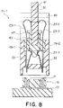
- Fig. 8 is a vertical sectional view of the multi-row connector illustrated in Figs. 6 and 7;
- Fig. 9 is another vertical sectional view of the multi-row connector illustrated in Figs. 6 and 7;
- Fig. 10 is a perspective view of resilient pieces for use with a modification in the multi-row connector depicted in any one of Figs. 1, 4, and 6.
- Referring now to Figs. 1 through 3, exemplarily only depicted is a multi-connector 11 using, as a plurality of flexible contact sheets, a plurality of flexible printed circuit boards having a plurality of conductive patterns according to a first embodiment of this invention. The
multi-row connector 11 is for establishing electric connection to a printedcircuit board 13 or a paired ormating connector 15 used as a mother board. The pairedconnector 15 comprises aninsulator block 16 and contact rows of a plurality ofcontacts 17 supported in theinsulator block 16. Each of thecontacts 17 has a contact portion and a terminal end connected to the circuit board as shown in Figs. 2 and 3. - The
multi-row connector 11 comprises afirst insulator block 19 having two sheet receivingslits 21 collectively as a sheet receiving hole. In themulti-row connector 11, a pair of insulatingflexible contact sheets 23 has individual front surfaces depicted in Fig. 1, one as seen and the other opposite to a direction of sight, and individual sheet ends depicted at bottom of theflexible contact sheets 23. It is possible as will be understood from the following to use a single flat flexible sheet as theflexible contact sheet 23. Rows ofparallel conductor patterns 25 are arranged to reach the sheet ends on each of the front surfaces. Theconductor patterns 25 are not less in number on each front surface than thecontacts 17 in each contact row so that thecontacts 17 of the contact rows may be brought into electric contact with theconductor patterns 25. Theflexible contact sheets 23 are put in thesheet receiving hole 21 in a back to back opposing relation, as is clear in Fig. 1, with the sheet ends brought onto a common plane. - In the
multi-row connector 11, asecond insulator block 27 has asheet receiving groove 29 for receiving theflexible contact sheets 23 with their sheet ends protruded through thecontact receiving groove 29. More specifically, thecontact receiving groove 29 has a bottom end which is in contact in Fig. 3 with the pairedconnector 15. An actuatingmember 31 is for actuating theflexible contact sheets 23 to bring theparallel conductor patterns 25 at the sheet ends near to thecontacts 17 after thesecond insulator block 27 is brought into contact with the pairedconnector 15 to place theconductor patterns 25 near at the sheet ends to thecontacts 17. - According to a salient feature of this invention, the
multi-row connector 11 comprises a pair of insulatingresilient pieces 33 having individual piece ends fixed to the sheet ends of theflexible contact sheet 23, respectively, and extended backwardly of theflexible contact sheet 23 to have individual free ends or extension portions extending away from the rear surfaces to be spaced apart by a predetermined distance and to be placed in thesheet receiving groove 29. The actuatingmember 31 has a first and a second diameter smaller and greater than the predetermined distance so as to be freely inserted between the free ends and to push the free ends apart when the actuatingmember 31 is inserted between the free ends to be subsequently positioned between the free ends with the first and the second diameters directed substantially perpendicular and parallel to the predetermined distance. - As best depicted in Figs. 2 and 3, the first and the second insulator blocks 19 and 27 have side surfaces parallel to a direction of the opposing relation of the
flexible contact sheets 23, namely, to a sheet of Fig. 2 or 3. The first and the second insulator blocks 19 and 27 have amember receiving hole 35 larger than a greater one of the first and the second diameters. After the first and the second insulator blocks 19 and 27 are put together, the actuatingmember 31 is inserted through themember receiving hole 35 between the free ends of the insulatingresilient pieces 33 with the first and the second diameters directed appropriately perpendicular and parallel (Fig. 2) to the predetermined distance. Later, the actuatingmember 31 is turned so that the first and the second diameters are directed substantially perpendicular and parallel (Fig. 3) to the predetermined distance. In this manner, the actuatingmember 31 serves as an operating cam for insertion through themember receiving hole 35. - The paired
connector 15 further has a receiving holes 18 for loosely receiving the sheet end of theflexible contact sheets 23 and the end portions of the insulatingresilient pieces 33 together, the contact portions of thecontacts 17 are exposed in the receiving holes 18. In the shown embodiment, each ofcontacts 17 is provided with each of the receiving holes 18. - In Fig. 3, where the actuating
member 31 is placed as the actuating cam between the free ends of the insulatingresilient pieces 33 with the second or greater diameter directed parallel to the predetermined distance, three forces F1, F2, and F3 for the insulatingresilient pieces 33 having a longitudinal length L, are related to one another in accordance with the following equations.
- Therefore,

- As a result, the force F1 becomes a minimal operating force by the use of the operating cam.
- Referring afresh to Figs. 4 and 5, the description will proceed to a modification of the multi-row connector depicted in Figs. 1 through 3.
- The
multi-row connector 11 further comprise acover member 37 for covering and receiving thefirst insulator block 19 on its top. Thecover member 37 has aninsertion portion 39 protruding in thesheet receiving hole 21 to serve as the actuatingmember 31 when inserted between the free ends. Theactuating meter 31 of Figs. 1 through 3 is no more separately necessary. - Referring now to Figs. 6 through 9 with Figs. 1 through 3 again referred to, attention will be directed to a multi-row connector 11-1 according to a second embodiment of this invention. Similar parts are designated by like reference numerals.
- This multi-row connector 11-1 is for further connection to a
daughter board 41 having a pair of board surfaces of a predetermined thickness between the board surfaces. Thedaughter board 41 has ashim end 43 of the predetermined thickness downwardly in Figs. 6 through 9. The predetermined thickness is not smaller than the predetermined distance. A plurality of conductive patterns 45 are formed on the board surfaces in correspondence to theconductor patterns 25. It is unnecessary that the conductive patterns 45 should reach a bottom end of theshim end 43. - The first insulator block is divided into first primary and secondary insulator blocks 19-1 and 19-2 having a pair of sheet receiving holes 21-1 and 21-2 collectively as the sheet receiving hole mentioned in connection with Figs. 1 through 3 for individually receiving the
flexible contact sheets 23. Theshim end 43 serves as the actuatingmember 31. The flexible contact sheets are now two separate flexible contact sheets 23-1 and 23-2 having tip ends, respectively. When pushed between the flexible contact sheets 23-1 and 23-2 downwardly of Figs. 6 through 9, thedaughter board 41 tucks the flexible contact sheets 23-1 and 23-2 with theconductor patterns 25 brought into contact with the conductive patterns 45 since the flexible contact sheets 23-1 and 23-2 are easily bent to the the board surfaces. - The
shim end 43 comprises an engaging edgeportion having flanges 47 forwardly and backwardly protruded from the board surfaces, respectively, for engaging with thefirst insulator block 19 as best shown in Fig. 9. Thefirst insulator block 19 has a shim end receiving opening between the first primary and the secondary insulator blocks 19-1 and 19-2. When theshim end 43 is put between the free ends, theflanges 47 abut thefirst insulator block 19. - The second insulator block 27-1 has a pinhead receiving holes 49. The
daughter board 41 has apinbody receiving hole 51 for alignment with thepinhead receiving hole 49. An insertion pin 53 is inserted in the pinhead and thepinbody receiving boles shim end 43 is put in the shim end receiving opening to bring the pinhead and thepinbody receiving holes first insulator block 19 from being inadvertently separated from thesecond insulator block 27. - Referring to Fig. 10, an insulating resilient piece 33-1 may be divided into left and right resilient pieces 55-1 and 55-2 and a
framework 57 if the free ends of the flexible contact sheets 23-1 and 23-2 are not stable in thesheet receiving groove 29 or 29-1. The resilient pieces 55-1 and 55-2 are enclosed by theframework 57. Use of theframe work 57 increases mechanical strength of the insulatingresilient pieces 33 described in conjunction with Figs. 1 through 3. - In the embodiment, this invention is described as regards a multi-row connector. However, it will be understood by those skilled in the art that the present invention can be applied for establishing an electrical connection between a flexible printed circuit board having a single or a plurality Of conductor patterns and a connecting object such as a printed circuit board.
Claims (11)
- An electrical connector for electrically connecting a flexible printed circuit board (23) to a connecting object (13), said flexible printed circuit board comprising a flexible insulator sheet with front and rear surfaces and a sheet end and a conductor pattern (25) extending on said front surface to said sheet end, which comprises:
an insulating resilient piece (33) having an end portion and an extension portion extending in a different direction from said end portion, said insulating resilient piece being attached to the rear surface of said flexible printed circuit board so that said end portion is arranged to the sheet end of said flexible printed circuit board and said extension portion extending away from the rear surface of said flexible printed circuit board;
a connecting member (15) for being electrically and mechanically connected to said connecting object, said connecting member comprising an insulator block (16) and a contact (17) supported in said insulator block, said contact having a terminal end connected to said connecting object and a contact portion, said connecting member having a receiving hole (18) for loosely receiving said end portion of said insulating resilient piece and said sheet end of said flexible printed circuit board together, said contact portion exposed in said receiving hole; and
an actuating member (31, 39, 41) for pressing said extension portion of said insulating resilient piece towards the rear surface of said flexible printed circuit board when said end portion of said insulating resilient piece and said sheet end of said flexible printed circuit board are received together in said receiving hole, whereby said conductor pattern of said flexible printed circuit board is pressed onto and is brought into contact with said contact portion. - An electrical connector as claimed in claim 1 or 1, which further comprises insulator support (19, 29) for supporting said flexible printed circuit board and said actuating member, said insulator support having a fitting portion for fitting to said insulator block.
- An electrical connector as claimed in claim 1 or 2, wherein said actuating member is an operating rod (31) rotatably mounted in said insulator support, said operating rod having an operating cam portion so that said operating cam pressing said extension portion of said insulating resilient piece towards said rear surface of said flexible printed circuit board when said operating rod is at a first rotating angle position.
- An electrical connector as claimed in claim 1 or 2, wherein said actuating member is an operating plate (39, 41) removably fitted into said insulator support, said operating plate pressing said extension portion of said insulating resilient piece towards said rear surface of said flexible printed circuit board when said operating plate is fitted into said insulator support.
- An electrical connector as claimed in claim 4, wherein said operating plate is a circuit board (41) which is electrically connected to said flexible printed circuit board at the opposite end thereof.
- A multi-row connector (11) for establishing electric connection to a paired connector (15) comprising contact rows of a plurality of contacts (17) in each contact row, said multi-row connector comprising: a first insulator block (19) having a sheet receiving hole (21); a pair of flexible contact sheets (23) having individual front surfaces and individual sheet ends with rows of parallel conductor patterns (25), not less in number than said contacts in each contact row, arranged on each of said front surfaces to reach said sheet ends and with said flexible contact sheets received in said sheet receiving hole in a back to back opposing relation; a second insulator block (27) having a sheet receiving groove (29) for receiving said flexible contact sheets with said sheet ends protruded through said sheet receiving groove; and an actuating member (31) for actuating said flexible contact sheets to bring said parallel conductor patterns at said sheet ends near to said contacts after said second insulator block is brought into contact with said paired connector to place said conductor patterns near at said sheet ends to said contacts; wherein:
said multi-row connector comprises a pair of insulating resilient pieces (33) having individual piece ends fixed to said sheet ends, respectively, and extended backwardly of said flexible contact sheets to have individual free ends spaced apart by a predetermined distance and to be placed in said sheet receiving groove;
said actuating member having a greater diameter greater than said predetermined distance so as to be freely inserted between said free ends and to push said free ends apart when said actuating member is inserted between said free ends to be subsequently positioned between said free ends with said greater diameter directed substantially perpendicularly to said predetermined distance. - A multi-row connector as claimed in claim 6, wherein said first and said second insulator blocks have side surfaces parallel to a direction of said opposing relation of said flexible contact sheets, said first and said second insulator blocks having a member receiving hole (35) greater than said greater diameter for receiving said actuating member in said side surfaces when put together, said actuating member serving as an operating cam for insertion through said member receiving hole.
- A multi-row connector as claimed in claim 6 or 7, further comprising a cover member (37) for covering and receiving said first insulator block on its top, said cover member having an insertion portion (39) protruding in said member receiving hole and having a thickness greater than said predetermined distance to serve as said actuating member when inserted between said free ends.
- A multi-row connector (11-1) as claimed in claims 6 to 8, said multi-row connector being for further connection to a daughter board (41) having a pair of board surfaces and a shim end (43) of a predetermined thickness between said board surfaces with a plurality of conductive patterns (45) formed on said board surfaces in correspondence to said conductor patterns, wherein said first insulator block has a pair of sheet receiving holes (21-1, 21-2) collectively as said sheet receiving hole for individually receiving said flexible contact sheets, said predetermined thickness being not smaller than said predetermined distance, said shim end serving as said actuating member tucking said flexible contact sheets with said conductor patterns brought into contact with said conductive patterns when said daughter board is pushed into said predetermined distance.
- A multi-row connector as claimed in claim 9, wherein said shim end has flanges (47) which abut said first insulator blocks when said shim end is put between said free ends.
- A multi-row connector as claimed in one of claims 6 to 10, wherein said second insulator block has a pinhead receiving hole (49), said daughter board having a pinbody receiving hole (51) for alignment with said pin-head receiving hole, an insertion pin (53) being inserted in said pinhead and said pinbody receiving holes after said shim end is put in said sheet receiving groove to bring said pinhead and said pinbody receiving holes in alignment.
Applications Claiming Priority (3)
| Application Number | Priority Date | Filing Date | Title |
|---|---|---|---|
| JP25659894 | 1994-10-21 | ||
| JP256598/94 | 1994-10-21 | ||
| JP25659894 | 1994-10-21 |
Publications (3)
| Publication Number | Publication Date |
|---|---|
| EP0708502A2 true EP0708502A2 (en) | 1996-04-24 |
| EP0708502A3 EP0708502A3 (en) | 1996-11-13 |
| EP0708502B1 EP0708502B1 (en) | 2000-03-22 |
Family
ID=17294861
Family Applications (1)
| Application Number | Title | Priority Date | Filing Date |
|---|---|---|---|
| EP95116688A Expired - Lifetime EP0708502B1 (en) | 1994-10-21 | 1995-10-23 | An assembly of an electrical connector and a flexible printed circuit board with an insulating resilient piece |
Country Status (4)
| Country | Link |
|---|---|
| US (1) | US5622505A (en) |
| EP (1) | EP0708502B1 (en) |
| DE (1) | DE69515789T2 (en) |
| TW (1) | TW280957B (en) |
Cited By (1)
| Publication number | Priority date | Publication date | Assignee | Title |
|---|---|---|---|---|
| CN1085877C (en) * | 1996-06-26 | 2002-05-29 | 阿尔卑斯电气株式会社 | Flexible circuit board fitting structure and recording copying device of using the same |
Families Citing this family (16)
| Publication number | Priority date | Publication date | Assignee | Title |
|---|---|---|---|---|
| JP2678886B2 (en) * | 1994-10-06 | 1997-11-19 | 日本航空電子工業株式会社 | Non-plugging / unplugging connector for plate circuit body |
| US5779498A (en) * | 1994-10-31 | 1998-07-14 | The Whitaker Corporation | Flat cable connector |
| JP2717376B2 (en) * | 1995-03-09 | 1998-02-18 | 日本航空電子工業株式会社 | ZIF connector |
| JP2717380B2 (en) * | 1995-05-30 | 1998-02-18 | 日本航空電子工業株式会社 | Card type connector for electronic device |
| FR2749446B1 (en) * | 1996-05-29 | 1998-07-24 | Cinch Connecteurs Sa | ELECTRICAL CONNECTION ASSEMBLY |
| US5913699A (en) * | 1997-11-03 | 1999-06-22 | Molex Incorporated | Laminated spring structure and flexible circuitry connector incorporating same |
| US5975934A (en) * | 1997-12-12 | 1999-11-02 | Japan Aviation Electronics Industry, Ltd. | Two-piece electrical connector of ZIF type using flexible printed circuit boards as contact elements |
| US5938453A (en) * | 1998-04-10 | 1999-08-17 | Japan Aviation Electronics Industry, Limited | Two-piece electrical connector having a reduced stature in a mating condition by provision of a flexible contact member bendable in one connector member |
| US5984704A (en) * | 1998-04-13 | 1999-11-16 | Japan Aviation Electronics Industry, Ltd. | Zif connector having means for keeping flexible contact sheet in tensile condition |
| US6012928A (en) * | 1998-08-28 | 2000-01-11 | Molex Incorporated | Microstrip edge card connector |
| US6854995B2 (en) * | 2001-11-07 | 2005-02-15 | Tyco Electronics Amp Gmbh | Connector for detachably connecting an electrically conductive foil to a contact |
| JP4322689B2 (en) * | 2004-01-19 | 2009-09-02 | 日本航空電子工業株式会社 | ZIF connector |
| TWM267625U (en) * | 2004-09-15 | 2005-06-11 | Shin-Feng Jian | Holding apparatus of pneumatic thin-film test |
| JP5739104B2 (en) * | 2010-01-29 | 2015-06-24 | モレックス インコーポレイテドMolex Incorporated | connector |
| US9979109B2 (en) * | 2015-11-10 | 2018-05-22 | Lenovo Enterprise Solutions (Singapore) Pte. Ltd. | Card stabilizer bracket |
| KR102516102B1 (en) * | 2017-11-28 | 2023-03-29 | 몰렉스 엘엘씨 | High speed connector |
Citations (4)
| Publication number | Priority date | Publication date | Assignee | Title |
|---|---|---|---|---|
| JPS5711105B2 (en) | 1977-04-06 | 1982-03-02 | ||
| US4881908A (en) | 1988-10-11 | 1989-11-21 | Beta Phase, Inc. | High density and high signal integrity connector |
| US4892487A (en) | 1989-06-15 | 1990-01-09 | Ibm Corporation | Connector assembly with movable carriage |
| US5102342A (en) | 1989-11-13 | 1992-04-07 | Augat Inc. | Modified high density backplane connector |
Family Cites Families (7)
| Publication number | Priority date | Publication date | Assignee | Title |
|---|---|---|---|---|
| AU563430B2 (en) * | 1984-02-21 | 1987-07-09 | Amp Incorporated | Circuit card edge connector |
| US4580867A (en) * | 1985-02-12 | 1986-04-08 | Molex Incorporated | Method and apparatus for terminating a reciprocable connector |
| US4911643A (en) * | 1988-10-11 | 1990-03-27 | Beta Phase, Inc. | High density and high signal integrity connector |
| US5044980A (en) * | 1990-01-16 | 1991-09-03 | Beta Phase, Inc. | High density and multiple insertion connector |
| US5316486A (en) * | 1990-05-29 | 1994-05-31 | Kel Corporation | Connector assembly for film circuitry |
| EP0613591B1 (en) * | 1991-11-18 | 1999-01-20 | Berg Electronics Manufacturing B.V. | Zero insertion force connector system for a flexible circuit |
| US5505625A (en) * | 1994-05-17 | 1996-04-09 | Beta Phase, Inc. | Connector assembly for electrically interconnecting two printed circuit board like members |
-
1995
- 1995-10-23 DE DE69515789T patent/DE69515789T2/en not_active Expired - Lifetime
- 1995-10-23 US US08/546,585 patent/US5622505A/en not_active Expired - Lifetime
- 1995-10-23 EP EP95116688A patent/EP0708502B1/en not_active Expired - Lifetime
- 1995-10-26 TW TW084111284A patent/TW280957B/zh not_active IP Right Cessation
Patent Citations (4)
| Publication number | Priority date | Publication date | Assignee | Title |
|---|---|---|---|---|
| JPS5711105B2 (en) | 1977-04-06 | 1982-03-02 | ||
| US4881908A (en) | 1988-10-11 | 1989-11-21 | Beta Phase, Inc. | High density and high signal integrity connector |
| US4892487A (en) | 1989-06-15 | 1990-01-09 | Ibm Corporation | Connector assembly with movable carriage |
| US5102342A (en) | 1989-11-13 | 1992-04-07 | Augat Inc. | Modified high density backplane connector |
Cited By (1)
| Publication number | Priority date | Publication date | Assignee | Title |
|---|---|---|---|---|
| CN1085877C (en) * | 1996-06-26 | 2002-05-29 | 阿尔卑斯电气株式会社 | Flexible circuit board fitting structure and recording copying device of using the same |
Also Published As
| Publication number | Publication date |
|---|---|
| DE69515789T2 (en) | 2000-08-03 |
| EP0708502A3 (en) | 1996-11-13 |
| US5622505A (en) | 1997-04-22 |
| DE69515789D1 (en) | 2000-04-27 |
| EP0708502B1 (en) | 2000-03-22 |
| TW280957B (en) | 1996-07-11 |
Similar Documents
| Publication | Publication Date | Title |
|---|---|---|
| EP0708502B1 (en) | An assembly of an electrical connector and a flexible printed circuit board with an insulating resilient piece | |
| US7458829B2 (en) | Electric connector having an excellent grounding function | |
| EP0961352B1 (en) | Multi-pin connector for flat cable | |
| US7445495B2 (en) | Flat circuit board electrical connector | |
| US7794285B1 (en) | Audio jack connector | |
| US8070528B2 (en) | Electrical connector having improved terminals | |
| US7021969B2 (en) | Connector allowing reduction in thickness of an apparatus to which the connector is to be mounted | |
| JPH06208874A (en) | Electrical connector for card reader | |
| EP1235304A1 (en) | Connector for flat circuit member | |
| US6561843B1 (en) | FPC connector | |
| EP0632549B1 (en) | Electrical connector assembly | |
| EP0191539A2 (en) | Electrical connecting terminal for a connector | |
| EP0542068B1 (en) | Female electrical contact | |
| US7121849B2 (en) | Electrical connector having a ground plane with independently configurable contacts | |
| CN112909662B (en) | Connector and connector assembly using same | |
| CN112909663B (en) | Shielding plate, terminal module using same and connector | |
| US8430685B2 (en) | Connector assembly | |
| GB2338842A (en) | Spring-assisted connector contact | |
| JP3016058B2 (en) | Electrical connector for card | |
| JPH0543479U (en) | connector | |
| JPH0229672Y2 (en) | ||
| US8535089B2 (en) | Connector assembly | |
| JPH054226Y2 (en) | ||
| EP0060024A1 (en) | Electric socket terminal | |
| JP2001110491A (en) | Electrical connector |
Legal Events
| Date | Code | Title | Description |
|---|---|---|---|
| PUAI | Public reference made under article 153(3) epc to a published international application that has entered the european phase |
Free format text: ORIGINAL CODE: 0009012 |
|
| AK | Designated contracting states |
Kind code of ref document: A2 Designated state(s): DE FR GB |
|
| PUAL | Search report despatched |
Free format text: ORIGINAL CODE: 0009013 |
|
| AK | Designated contracting states |
Kind code of ref document: A3 Designated state(s): DE FR GB |
|
| 17P | Request for examination filed |
Effective date: 19970403 |
|
| 17Q | First examination report despatched |
Effective date: 19981007 |
|
| GRAG | Despatch of communication of intention to grant |
Free format text: ORIGINAL CODE: EPIDOS AGRA |
|
| GRAG | Despatch of communication of intention to grant |
Free format text: ORIGINAL CODE: EPIDOS AGRA |
|
| GRAG | Despatch of communication of intention to grant |
Free format text: ORIGINAL CODE: EPIDOS AGRA |
|
| GRAH | Despatch of communication of intention to grant a patent |
Free format text: ORIGINAL CODE: EPIDOS IGRA |
|
| GRAH | Despatch of communication of intention to grant a patent |
Free format text: ORIGINAL CODE: EPIDOS IGRA |
|
| GRAA | (expected) grant |
Free format text: ORIGINAL CODE: 0009210 |
|
| AK | Designated contracting states |
Kind code of ref document: B1 Designated state(s): DE FR GB |
|
| RIC1 | Information provided on ipc code assigned before grant |
Free format text: 7H 01R 12/16 A, 7H 01R 12/24 B, 7H 01R 12/22 B |
|
| REF | Corresponds to: |
Ref document number: 69515789 Country of ref document: DE Date of ref document: 20000427 |
|
| ET | Fr: translation filed | ||
| PLBE | No opposition filed within time limit |
Free format text: ORIGINAL CODE: 0009261 |
|
| STAA | Information on the status of an ep patent application or granted ep patent |
Free format text: STATUS: NO OPPOSITION FILED WITHIN TIME LIMIT |
|
| 26N | No opposition filed | ||
| REG | Reference to a national code |
Ref country code: GB Ref legal event code: IF02 |
|
| PGFP | Annual fee paid to national office [announced via postgrant information from national office to epo] |
Ref country code: FR Payment date: 20131009 Year of fee payment: 19 Ref country code: DE Payment date: 20131016 Year of fee payment: 19 Ref country code: GB Payment date: 20131023 Year of fee payment: 19 |
|
| REG | Reference to a national code |
Ref country code: DE Ref legal event code: R119 Ref document number: 69515789 Country of ref document: DE |
|
| GBPC | Gb: european patent ceased through non-payment of renewal fee |
Effective date: 20141023 |
|
| PG25 | Lapsed in a contracting state [announced via postgrant information from national office to epo] |
Ref country code: GB Free format text: LAPSE BECAUSE OF NON-PAYMENT OF DUE FEES Effective date: 20141023 Ref country code: DE Free format text: LAPSE BECAUSE OF NON-PAYMENT OF DUE FEES Effective date: 20150501 |
|
| REG | Reference to a national code |
Ref country code: FR Ref legal event code: ST Effective date: 20150630 |
|
| PG25 | Lapsed in a contracting state [announced via postgrant information from national office to epo] |
Ref country code: FR Free format text: LAPSE BECAUSE OF NON-PAYMENT OF DUE FEES Effective date: 20141031 |