EP0708244A2 - Reduced icing air valve - Google Patents
Reduced icing air valve Download PDFInfo
- Publication number
- EP0708244A2 EP0708244A2 EP19950307360 EP95307360A EP0708244A2 EP 0708244 A2 EP0708244 A2 EP 0708244A2 EP 19950307360 EP19950307360 EP 19950307360 EP 95307360 A EP95307360 A EP 95307360A EP 0708244 A2 EP0708244 A2 EP 0708244A2
- Authority
- EP
- European Patent Office
- Prior art keywords
- valve
- exhaust
- air
- chambers
- supply
- Prior art date
- Legal status (The legal status is an assumption and is not a legal conclusion. Google has not performed a legal analysis and makes no representation as to the accuracy of the status listed.)
- Granted
Links
Images


Classifications
-
- F—MECHANICAL ENGINEERING; LIGHTING; HEATING; WEAPONS; BLASTING
- F04—POSITIVE - DISPLACEMENT MACHINES FOR LIQUIDS; PUMPS FOR LIQUIDS OR ELASTIC FLUIDS
- F04B—POSITIVE-DISPLACEMENT MACHINES FOR LIQUIDS; PUMPS
- F04B43/00—Machines, pumps, or pumping installations having flexible working members
- F04B43/02—Machines, pumps, or pumping installations having flexible working members having plate-like flexible members, e.g. diaphragms
- F04B43/06—Pumps having fluid drive
- F04B43/073—Pumps having fluid drive the actuating fluid being controlled by at least one valve
- F04B43/0733—Pumps having fluid drive the actuating fluid being controlled by at least one valve with fluid-actuated pump inlet or outlet valves; with two or more pumping chambers in series
-
- Y—GENERAL TAGGING OF NEW TECHNOLOGICAL DEVELOPMENTS; GENERAL TAGGING OF CROSS-SECTIONAL TECHNOLOGIES SPANNING OVER SEVERAL SECTIONS OF THE IPC; TECHNICAL SUBJECTS COVERED BY FORMER USPC CROSS-REFERENCE ART COLLECTIONS [XRACs] AND DIGESTS
- Y10—TECHNICAL SUBJECTS COVERED BY FORMER USPC
- Y10T—TECHNICAL SUBJECTS COVERED BY FORMER US CLASSIFICATION
- Y10T137/00—Fluid handling
- Y10T137/2496—Self-proportioning or correlating systems
- Y10T137/2544—Supply and exhaust type
Landscapes
- Engineering & Computer Science (AREA)
- Mechanical Engineering (AREA)
- General Engineering & Computer Science (AREA)
- Reciprocating Pumps (AREA)
- Details Of Reciprocating Pumps (AREA)
Abstract
Description
- This invention relates generally to air valves and more particularly to an air valve designed to minimise icing and improve efficiency for a diaphragm pump or the like. Current diaphragm pumps, as well as other pneumatic devices, experience two problems: (1) icing which results in reduced/erratic performance of the pump, and (2) inefficiency resulting from oversized valve porting to overcome icing provided in current design.
- The air motor valving used to control reciprocating motion in current designs handles both the feed air to the driving piston or diaphragm and exhaust air through the same porting. In order to obtain fast switch over and high average output pressure it is important the piston/diaphragm chambers are exhausted as quickly as possible. In order for this to occur the porting through the valve is made as large as possible. The large port area allows the air to exhaust rapidly; however, in doing so large temperature drops are generated in the valve. Any water in the air will drop out and freeze. As with most valves the geometry of the flow path through the valve may contain areas where the flow may be choked followed by large expansions and stagnation areas. These are the areas where water collects and freezes.
- The valving itself may also become extremely cold since exhaust air is continually flowing through the valve and may cause water in the incoming air to freeze.
- The large port area required to dump the exhaust is also used to feed the air chamber. During the fill cycle the large porting allows the chamber to fill rapidly and reach a high mean effective pressure in the chamber at high cycle rates. The head pressures developed at high flow rates are relatively low which requires a finite chamber pressure and volume to move the fluid at the required flow rate and head. By sizing the inlet porting to meet flow requirements the volume of air required is reduced as well as the amount to exhaust.
- According to the present invention, there is provided a reduced icing air valve comprising a shiftable valve for alternately supplying compressed air through first and second supply ports to opposed first and second actuating chambers respectively and for effecting alternating exhaust of said chambers; characterised in that said valve is provided with bypass means intermediate said valve and each of said chambers for bypassing said valve by exhaust air.
- For a better understanding of the invention and to show how the same may be carried into effect, reference will now be made, by way of example, to the accompanying drawings, in which:-
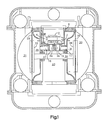
- Figure 1 is a cross-section of a diaphragm pump showing an air motor major valve;
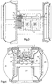
- Figure 2 is a cross-section of a reduced icing air valve showing a pilot valve;
- Figure 3 is a cross-section detail of the pilot valve in an extreme left-hand position;
- Figure 4 is a cross-section detail showing the air motor major valve spool in an extreme left-hand position;
- Figure 5 is a cross-section detail showing the pilot valve in an extreme right-hand position; and
- Figure 6 is a cross-section detail showing the major valve in an extreme right-hand position.
- In order to exhaust the air chambers rapidly without increasing the fill cycle porting, an alternative flow path is required.
- Figure 1 is a cross-sectional view of the air motor major valve. Figure 2 is a view of the pilot valve. Both valves are shown in their dead centre positions.
- In Figure 1, the major valve consists of a
spool 1,valve block 2,valve plate 3,power piston 4, quickdump check valves housing 6. Figure 2 shows the pilot valve consisting of apilot piston 7,push rod 8 andactuator pins same cavity 12 which is pressurised with supply air. Thepower piston 4 andpilot piston 7 are differential pistons. Air pressure acting on the small diameters of the pistons will force the pistons to the left when a pilot signal is not present inchambers chambers - In Figure 4 the
spool 1 is shown in its extreme left position as is thepilot piston 7 in Figure 3. Air in thecavity 12 flows through anorifice 13 created between thespool 1 andvalve block 2 through aport 14 in thevalve plate 3. The air impinging on the upper surface of thecheck valve 5a forces it to seat and seal off theexhaust port 15. The air flow deforms the lips of the elastomeric check valve as shown in Figure 4. Air flows around the valve into aport 17 and into adiaphragm chamber 18. Air pressure acting on thediaphragm 19 forces it to the right expelling fluid from afluid chamber 20 through an outlet check valve. - Operation of the fluid check valves controls movement of fluid in and out of the fluid chambers causing them to function as single acting pumps. By connecting the two chambers through external manifolds output flow from the pump becomes relatively constant.
- At the same time as the
chamber 18 is filling, the air above thecheck valve 5b has been exhausted through anorifice 21, aport 22 and into anexhaust cavity 23. This action causes a pressure differential to occur between chambers 24 and 25. The lips of thecheck valve 5b relax against the wall of the chamber 25. As air begins to flow from anair chamber 26 through aport 27, it forces thecheck valve 5b to move upward and seats against thevalve plate 3 and seal off a port 28 and opens theport 16. Exhaust air is dumped into thecavity 23. - The
diaphragm 19 is connected to thediaphragm 29 through ashaft 30 which causes them to reciprocate together. As thediaphragm 19 traverses to the right thediaphragm 29 creates a suction on afluid chamber 31 which causes fluid to flow into thefluid chamber 31 through an inlet check. As the diaphragm assembly approaches the end of the stroke,diaphragm washer 33 pushes theactuator pin 9a (Figure 5) to the right. The pin in turn pushes thepilot piston 7 to the right to the position shown in Figure 5. O-ring 35 is engaged in bore ofsleeve 34 and O-ring 36 exits the bore to allow air to flow from theair cavity 12 through theport 37 in thepilot piston 7 and into thecavity 10. Air pressure acting on the large diameter of thepilot piston 7 causes the piston to shift to the right. - The air that flows into the
chamber 10 also flows into thechamber 11 through apassage 38 which connects the two bores. When the pressure reaches approximately 50% of the supply pressure, thepower piston 4 shifts thespool 1 to the position shown in Figure 6. Air being supplied to thechamber 18 is shut off and thechamber 38 is exhausted through anorifice 41. This causes thecheck valve 5a to shift connectingair chamber 18 toexhaust port 15. At the same time theair chamber 26 is connected to supply air through theorifice 40 andport 28 and 27. The air pressure acting on thediaphragm 29 causes the diaphragms to reverse direction expelling fluid from thefluid chamber 31 through an outlet check while thediaphragm 19 evacuates thefluid chamber 20 to draw fluid into thefluid chamber 20. - As the
diaphragm 19 approaches the end of its stroke, thediaphragm washer 39 pushes theactuator pin 9b. The motion is transmitted through thepush rod 8 to thepilot piston 7, moving it to the trip point shown in Figure 2. The O-ring 36 re-enters the bore in thesleeve 34 and seals off the air supply to thechambers ring 35 exits the bore to connect thechambers port 37 in thepilot piston 7. The air from the two chambers flows through the port 42 intoexhaust cavity 23. The air inair cavity 12 acting on the small diameters ofpistons power piston 4 will pull thespool 1 to the left to begin a new cycle. - Different arrangements to actuate the quick dump valves can be used which include poppet valves, "D" valves and other mechanical or pneumatically actuated valves.
Claims (8)
- A reduced icing air valve comprising a shiftable valve for alternately supplying compressed air through first and second supply ports (17, 27) to opposed first and second actuating chambers (18, 26) respectively and for effecting alternating exhaust of said chambers; characterised in that said valve is provided with bypass means (15, 16) intermediate said valve and each of said chambers for bypassing said valve by exhaust air.
- A reduced icing air valve for a reciprocating double diaphragm pump comprising a shiftable valve for alternately supplying compressed air through first and second supply ports (17, 27) to opposed first and second actuating chambers (18, 26) respectively and for effecting alternating exhaust of said chambers; characterised in that said valve is further provided with bypass means intermediate said valve and each of said chambers for bypassing said valve by exhaust air.
- A valve according to claim 2, wherein said shiftable valve is a pneumatically operated spool valve (1, 2).
- A valve according to claim 2 or 3, wherein said opposed first and second actuating chambers (18, 26) comprise diaphragm operating chambers for mechanically connected diaphragms (19, 29), wherein pressurisation of one of said opposed first and second actuating chambers effects exhaust of the other of said opposed first and second actuating chambers.
- A valve according to any one of the preceding claims, wherein said bypass means comprises a pressure operated check valve (5a, 5b) closed to exhaust by the supply of compressed air to its associated actuating chamber and open to exhaust, upon ceasing the supply of compressed air, by return flow of exhaust air.
- A valve according to claim 5, wherein said pressure operated check valve further comprises a deformable elastomeric check co-acting with an exhaust port (15) to close it off upon supply of compressed air and co-acting with said supply port to close off said supply port to said valve upon exhaust of said actuating chamber.
- A valve according to claim 6, wherein said exhaust port exits to atmosphere.
- A valve according to claim 5, 6 or 7, wherein said pressure operated check valve (5a, 5b) further coacts with the respective supply port to prevent return flow of exhaust air to said shiftable valve.
Applications Claiming Priority (2)
| Application Number | Priority Date | Filing Date | Title |
|---|---|---|---|
| US08/324,201 US5584666A (en) | 1994-10-17 | 1994-10-17 | Reduced icing air valve |
| US324201 | 2005-12-29 |
Publications (3)
| Publication Number | Publication Date |
|---|---|
| EP0708244A2 true EP0708244A2 (en) | 1996-04-24 |
| EP0708244A3 EP0708244A3 (en) | 1996-10-23 |
| EP0708244B1 EP0708244B1 (en) | 2000-08-09 |
Family
ID=23262547
Family Applications (1)
| Application Number | Title | Priority Date | Filing Date |
|---|---|---|---|
| EP19950307360 Expired - Lifetime EP0708244B1 (en) | 1994-10-17 | 1995-10-16 | Double diaphragm pump |
Country Status (5)
| Country | Link |
|---|---|
| US (1) | US5584666A (en) |
| EP (1) | EP0708244B1 (en) |
| JP (1) | JPH08200211A (en) |
| CA (1) | CA2160498C (en) |
| DE (1) | DE69518295T2 (en) |
Families Citing this family (25)
| Publication number | Priority date | Publication date | Assignee | Title |
|---|---|---|---|---|
| US5957670A (en) * | 1997-08-26 | 1999-09-28 | Wilden Pump & Engineering Co. | Air driven diaphragm pump |
| US6152705A (en) * | 1998-07-15 | 2000-11-28 | Wilden Pump & Engineering Co. | Air drive pumps and components therefor |
| US6168394B1 (en) * | 1999-06-18 | 2001-01-02 | Wilden Pump & Engineering Co. | Air driven double diaphragm pump |
| US6644941B1 (en) | 2002-04-18 | 2003-11-11 | Ingersoll-Rand Company | Apparatus and method for reducing ice formation in gas-driven motors |
| US6901960B2 (en) * | 2002-09-06 | 2005-06-07 | Ingersoll-Rand Company | Double diaphragm pump including spool valve air motor |
| US6722256B2 (en) * | 2002-09-12 | 2004-04-20 | Ingersoll-Rand Company | Reduced icing valves and gas-driven motor and diaphragm pump incorporating same |
| US6865981B2 (en) * | 2003-03-11 | 2005-03-15 | Ingersoll-Rand Company | Method of producing a pump |
| US6883417B2 (en) * | 2003-03-19 | 2005-04-26 | Ingersoll-Rand Company | Connecting configuration for a diaphragm in a diaphragm pump |
| US6962487B2 (en) * | 2003-08-07 | 2005-11-08 | Versa-Matic Tool, Inc. | Fluid driven pump with improved exhaust port arrangement |
| US7367785B2 (en) * | 2004-03-19 | 2008-05-06 | Ingersoll-Rand Company | Reduced icing valves and gas-driven motor and reciprocating pump incorporating same |
| BRPI0614668A2 (en) * | 2005-07-29 | 2011-04-12 | Graco Minnesota Inc | reciprocating piston pump with air valve, detent and moving head |
| US7587897B2 (en) * | 2007-04-10 | 2009-09-15 | Illinois Tool Works Inc. | Magnetically sequenced pneumatic motor |
| US7603854B2 (en) * | 2007-04-10 | 2009-10-20 | Illinois Tool Works Inc. | Pneumatically self-regulating valve |
| US7603855B2 (en) * | 2007-04-10 | 2009-10-20 | Illinois Tool Works Inc. | Valve with magnetic detents |
| US20090010768A1 (en) * | 2007-07-03 | 2009-01-08 | Versa-Matic Pump, Inc. | Pumping apparatus for shear-sensitive fluids |
| US8167586B2 (en) * | 2008-08-22 | 2012-05-01 | Ingersoll-Rand Company | Valve assembly with low resistance pilot shifting |
| EP2753797A4 (en) | 2011-09-09 | 2015-04-08 | Ingersoll Rand Co | Air motor having a programmable logic controller interface and a method of retrofitting an air motor |
| EP2771127B1 (en) | 2011-10-27 | 2017-07-12 | Graco Minnesota Inc. | Sprayer fluid supply with collapsible liner |
| WO2013063294A1 (en) | 2011-10-27 | 2013-05-02 | Graco Minnesota Inc. | Melter cartridge |
| CN102878065B (en) * | 2012-10-26 | 2015-06-10 | 上海边锋泵业制造有限公司 | Pneumatic diaphragm pump with built-in electromagnetic valve |
| DE102014006759A1 (en) * | 2014-05-08 | 2015-11-12 | Dürr Systems GmbH | Exhaust air duct for a coating agent pump |
| US9796492B2 (en) | 2015-03-12 | 2017-10-24 | Graco Minnesota Inc. | Manual check valve for priming a collapsible fluid liner for a sprayer |
| CN104847653A (en) * | 2015-05-27 | 2015-08-19 | 张伟伟 | Regulating and controlling valve |
| NL2021314B1 (en) * | 2018-07-16 | 2020-01-24 | Noord Jan | Reciprocating piston motor, motor-pump assembly and method for driving a pump |
| CN115739435A (en) | 2019-05-31 | 2023-03-07 | 固瑞克明尼苏达有限公司 | Hand-held fluid sprayer |
Family Cites Families (12)
| Publication number | Priority date | Publication date | Assignee | Title |
|---|---|---|---|---|
| US3304126A (en) * | 1965-02-15 | 1967-02-14 | Gorman Rupp Co | Material handling apparatus and methods |
| US3635125A (en) * | 1969-03-21 | 1972-01-18 | Nordson Corp | Double-acting hydraulic pump and air motor therefor |
| US3838946A (en) * | 1971-07-12 | 1974-10-01 | Dorr Oliver Inc | Air pressure-actuated double-acting diaphragm pump |
| BE792041A (en) * | 1971-11-30 | 1973-03-16 | Adeola Ag | INVERSION DEVICE FOR THE PISTON CONTROL OF A PNEUMATIC MOTOR UNIT |
| US3791768A (en) * | 1972-06-16 | 1974-02-12 | W Wanner | Fluid pump |
| DE8107889U1 (en) * | 1981-03-18 | 1981-10-22 | Festo-Maschinenfabrik Gottlieb Stoll, 7300 Esslingen | PNEUMATIC VALVE ARRANGEMENT |
| EP0061706A1 (en) * | 1981-03-28 | 1982-10-06 | DEPA GmbH | Air-pressure actuated double-diaphragm pump |
| US4854832A (en) * | 1987-08-17 | 1989-08-08 | The Aro Corporation | Mechanical shift, pneumatic assist pilot valve for diaphragm pump |
| US5232352A (en) * | 1992-04-06 | 1993-08-03 | Holcomb Corporation | Fluid activated double diaphragm pump |
| US5277555A (en) * | 1992-12-31 | 1994-01-11 | Ronald L. Robinson | Fluid activated double diaphragm pump |
| US5326234A (en) * | 1993-02-17 | 1994-07-05 | Versa-Matic Tool, Inc. | Fluid driven pump |
| US5366353A (en) * | 1994-04-13 | 1994-11-22 | Hand Kent P | Air valve with bleed feature to inhibit icing |
-
1994
- 1994-10-17 US US08/324,201 patent/US5584666A/en not_active Expired - Lifetime
-
1995
- 1995-10-13 CA CA 2160498 patent/CA2160498C/en not_active Expired - Lifetime
- 1995-10-16 DE DE1995618295 patent/DE69518295T2/en not_active Expired - Lifetime
- 1995-10-16 EP EP19950307360 patent/EP0708244B1/en not_active Expired - Lifetime
- 1995-10-17 JP JP26809595A patent/JPH08200211A/en active Pending
Non-Patent Citations (1)
| Title |
|---|
| None |
Also Published As
| Publication number | Publication date |
|---|---|
| CA2160498C (en) | 2006-10-10 |
| US5584666A (en) | 1996-12-17 |
| EP0708244A3 (en) | 1996-10-23 |
| EP0708244B1 (en) | 2000-08-09 |
| CA2160498A1 (en) | 1996-04-18 |
| JPH08200211A (en) | 1996-08-06 |
| DE69518295D1 (en) | 2000-09-14 |
| DE69518295T2 (en) | 2001-03-29 |
Similar Documents
| Publication | Publication Date | Title |
|---|---|---|
| EP0708244B1 (en) | Double diaphragm pump | |
| EP0711905B1 (en) | Improved mechanical shift, pneumatic assist pilot valve | |
| US6644941B1 (en) | Apparatus and method for reducing ice formation in gas-driven motors | |
| JP3555723B2 (en) | Hydraulic operating unit and method of exhausting hydraulic operating unit | |
| CA1208492A (en) | Diaphragm pump | |
| US6210131B1 (en) | Fluid intensifier having a double acting power chamber with interconnected signal rods | |
| US5616005A (en) | Fluid driven recipricating apparatus | |
| US5240390A (en) | Air valve actuator for reciprocable machine | |
| CA1048462A (en) | Variable volume clearance chamber for compressors | |
| EP0304210A2 (en) | Double diaphragm pumps | |
| US6722256B2 (en) | Reduced icing valves and gas-driven motor and diaphragm pump incorporating same | |
| US4296672A (en) | Reciprocating piston-cylinder combination and valving control therefor | |
| US8186972B1 (en) | Multi-stage expansible chamber pneumatic system | |
| US5885061A (en) | Pneumatic pump | |
| CA2640797C (en) | Control system for reciprocating device | |
| US5007812A (en) | Hydraulic pump with pulsating high and low pressure outputs | |
| US7367785B2 (en) | Reduced icing valves and gas-driven motor and reciprocating pump incorporating same | |
| US11519267B2 (en) | Method and device for expanding a gas with a reciprocating-piston machine | |
| RU19404U1 (en) | FLUID PRESSURE AMPLIFIER | |
| KR101830165B1 (en) | Actuator for valve | |
| US6736612B2 (en) | Pump | |
| EP0773346A1 (en) | Compressed gas motor | |
| JPH0527681Y2 (en) | ||
| JPH01320301A (en) | Change-over controller for reciprocating type actuator | |
| JPH1047240A (en) | Booster pump |
Legal Events
| Date | Code | Title | Description |
|---|---|---|---|
| PUAI | Public reference made under article 153(3) epc to a published international application that has entered the european phase |
Free format text: ORIGINAL CODE: 0009012 |
|
| AK | Designated contracting states |
Kind code of ref document: A2 Designated state(s): DE FR GB IT |
|
| PUAL | Search report despatched |
Free format text: ORIGINAL CODE: 0009013 |
|
| AK | Designated contracting states |
Kind code of ref document: A3 Designated state(s): DE FR GB IT |
|
| RAP1 | Party data changed (applicant data changed or rights of an application transferred) |
Owner name: INGERSOLL-RAND COMPANY |
|
| 17P | Request for examination filed |
Effective date: 19970412 |
|
| 17Q | First examination report despatched |
Effective date: 19990510 |
|
| RTI1 | Title (correction) |
Free format text: DOUBLE DIAPHRAGM PUMP |
|
| GRAG | Despatch of communication of intention to grant |
Free format text: ORIGINAL CODE: EPIDOS AGRA |
|
| 17Q | First examination report despatched |
Effective date: 19990510 |
|
| GRAG | Despatch of communication of intention to grant |
Free format text: ORIGINAL CODE: EPIDOS AGRA |
|
| GRAH | Despatch of communication of intention to grant a patent |
Free format text: ORIGINAL CODE: EPIDOS IGRA |
|
| GRAH | Despatch of communication of intention to grant a patent |
Free format text: ORIGINAL CODE: EPIDOS IGRA |
|
| GRAA | (expected) grant |
Free format text: ORIGINAL CODE: 0009210 |
|
| AK | Designated contracting states |
Kind code of ref document: B1 Designated state(s): DE FR GB IT |
|
| REF | Corresponds to: |
Ref document number: 69518295 Country of ref document: DE Date of ref document: 20000914 |
|
| ITF | It: translation for a ep patent filed |
Owner name: ING. A. GIAMBROCONO & C. S.R.L. |
|
| ET | Fr: translation filed | ||
| PLBE | No opposition filed within time limit |
Free format text: ORIGINAL CODE: 0009261 |
|
| STAA | Information on the status of an ep patent application or granted ep patent |
Free format text: STATUS: NO OPPOSITION FILED WITHIN TIME LIMIT |
|
| 26N | No opposition filed | ||
| REG | Reference to a national code |
Ref country code: GB Ref legal event code: IF02 |
|
| PGFP | Annual fee paid to national office [announced via postgrant information from national office to epo] |
Ref country code: GB Payment date: 20140924 Year of fee payment: 20 |
|
| PGFP | Annual fee paid to national office [announced via postgrant information from national office to epo] |
Ref country code: DE Payment date: 20140924 Year of fee payment: 20 Ref country code: FR Payment date: 20141021 Year of fee payment: 20 |
|
| PGFP | Annual fee paid to national office [announced via postgrant information from national office to epo] |
Ref country code: IT Payment date: 20140926 Year of fee payment: 20 |
|
| REG | Reference to a national code |
Ref country code: DE Ref legal event code: R071 Ref document number: 69518295 Country of ref document: DE |
|
| REG | Reference to a national code |
Ref country code: GB Ref legal event code: PE20 Expiry date: 20151015 |
|
| PG25 | Lapsed in a contracting state [announced via postgrant information from national office to epo] |
Ref country code: GB Free format text: LAPSE BECAUSE OF EXPIRATION OF PROTECTION Effective date: 20151015 |