EP0708014A1 - Anchoring plate - Google Patents
Anchoring plate Download PDFInfo
- Publication number
- EP0708014A1 EP0708014A1 EP95307385A EP95307385A EP0708014A1 EP 0708014 A1 EP0708014 A1 EP 0708014A1 EP 95307385 A EP95307385 A EP 95307385A EP 95307385 A EP95307385 A EP 95307385A EP 0708014 A1 EP0708014 A1 EP 0708014A1
- Authority
- EP
- European Patent Office
- Prior art keywords
- plate
- rivet
- metal structure
- plate according
- anchor
- Prior art date
- Legal status (The legal status is an assumption and is not a legal conclusion. Google has not performed a legal analysis and makes no representation as to the accuracy of the status listed.)
- Granted
Links
- 238000004873 anchoring Methods 0.000 title description 24
- 239000002184 metal Substances 0.000 claims abstract description 30
- 238000003466 welding Methods 0.000 claims abstract description 11
- 239000000463 material Substances 0.000 claims description 7
- 229910000831 Steel Inorganic materials 0.000 claims description 4
- 239000010959 steel Substances 0.000 claims description 4
- 238000010276 construction Methods 0.000 claims description 3
- 230000003014 reinforcing effect Effects 0.000 claims 1
- 238000009966 trimming Methods 0.000 claims 1
- 230000002787 reinforcement Effects 0.000 abstract description 12
- 210000002105 tongue Anatomy 0.000 description 8
- 238000005096 rolling process Methods 0.000 description 6
- 230000000694 effects Effects 0.000 description 5
- 230000000750 progressive effect Effects 0.000 description 3
- 238000005516 engineering process Methods 0.000 description 2
- 238000000034 method Methods 0.000 description 2
- 239000011265 semifinished product Substances 0.000 description 2
- 229910000975 Carbon steel Inorganic materials 0.000 description 1
- 239000010962 carbon steel Substances 0.000 description 1
- 230000006866 deterioration Effects 0.000 description 1
- 230000013011 mating Effects 0.000 description 1
- 238000010079 rubber tapping Methods 0.000 description 1
- 238000007493 shaping process Methods 0.000 description 1
Images



Classifications
-
- B—PERFORMING OPERATIONS; TRANSPORTING
- B60—VEHICLES IN GENERAL
- B60J—WINDOWS, WINDSCREENS, NON-FIXED ROOFS, DOORS, OR SIMILAR DEVICES FOR VEHICLES; REMOVABLE EXTERNAL PROTECTIVE COVERINGS SPECIALLY ADAPTED FOR VEHICLES
- B60J5/00—Doors
- B60J5/04—Doors arranged at the vehicle sides
- B60J5/042—Reinforcement elements
- B60J5/0422—Elongated type elements, e.g. beams, cables, belts or wires
- B60J5/0423—Elongated type elements, e.g. beams, cables, belts or wires characterised by position in the lower door structure
- B60J5/0431—Elongated type elements, e.g. beams, cables, belts or wires characterised by position in the lower door structure the elements being arranged at the hinge area
-
- B—PERFORMING OPERATIONS; TRANSPORTING
- B60—VEHICLES IN GENERAL
- B60J—WINDOWS, WINDSCREENS, NON-FIXED ROOFS, DOORS, OR SIMILAR DEVICES FOR VEHICLES; REMOVABLE EXTERNAL PROTECTIVE COVERINGS SPECIALLY ADAPTED FOR VEHICLES
- B60J5/00—Doors
- B60J5/04—Doors arranged at the vehicle sides
- B60J5/042—Reinforcement elements
- B60J5/0422—Elongated type elements, e.g. beams, cables, belts or wires
- B60J5/0423—Elongated type elements, e.g. beams, cables, belts or wires characterised by position in the lower door structure
- B60J5/0433—Elongated type elements, e.g. beams, cables, belts or wires characterised by position in the lower door structure the elements being arranged at the lock area
-
- B—PERFORMING OPERATIONS; TRANSPORTING
- B62—LAND VEHICLES FOR TRAVELLING OTHERWISE THAN ON RAILS
- B62D—MOTOR VEHICLES; TRAILERS
- B62D21/00—Understructures, i.e. chassis frame on which a vehicle body may be mounted
- B62D21/09—Means for mounting load bearing surfaces
-
- F—MECHANICAL ENGINEERING; LIGHTING; HEATING; WEAPONS; BLASTING
- F16—ENGINEERING ELEMENTS AND UNITS; GENERAL MEASURES FOR PRODUCING AND MAINTAINING EFFECTIVE FUNCTIONING OF MACHINES OR INSTALLATIONS; THERMAL INSULATION IN GENERAL
- F16B—DEVICES FOR FASTENING OR SECURING CONSTRUCTIONAL ELEMENTS OR MACHINE PARTS TOGETHER, e.g. NAILS, BOLTS, CIRCLIPS, CLAMPS, CLIPS OR WEDGES; JOINTS OR JOINTING
- F16B37/00—Nuts or like thread-engaging members
- F16B37/04—Devices for fastening nuts to surfaces, e.g. sheets, plates
- F16B37/06—Devices for fastening nuts to surfaces, e.g. sheets, plates by means of welding or riveting
Definitions
- This invention concerns a plate for anchoring components on a metal sheet, including threaded sleeves obtained by stamping a part of the plate, to receive fixing screws of those components.
- the plate is constituted of metal having hardness from 40 to 50 Rockwell "C”.
- the sleeves may have an enlarged end portion near the plate and an internal screw thread that is produced by rolling. Before a hardening operation on the plate, the sleeves have their extreme edge farther from the plate radially deformed by rolling, so that first turns of the thread are oval, to produce a self-locking effect.
- an anchoring plate is proposed in European patent No. 333,953.
- a plate is produced starting from a relatively thin rough plate of a medium hardness steel, that is treated by a progressive die to form anchoring sleeves on the plate itself.
- the threading of each sleeve is accomplished by rolling, followed by a hardening operation, so that the finished part is lighter and more resistant than conventional plates.
- each sleeve can be rolled at its free end to ovalize the sleeve threads and produce a self-locking effect.
- FIGS. 1 and 2 of the annexed drawings are perspective views showing two opposite sides of an anchoring plate according to the invention of European Patent No. 333,953.
- numeral 1 indicates a relatively thin plate of a hard material.
- plate 1 is a carbon steel 1050 having a Rockwell hardness from 40 to 50. Plate 1 still can be treated by known thermic hardening procedures. Maintaining the same hardness, it is possible to have a low plate thickness and so obtain a lower weight in comparison to traditional anchoring plates.
- a plate like the one shown in FIGS. 1 and 2 could be produced from an initial 1.6 mm. thick semi-finished product.
- a progressive die operation is performed on the semi-finished product producing the required sleeves 2 extending perpendicular to the main surface of the plate.
- a progressive die By employing a progressive die it is possible to make longer sleeves than the conventional extruded ones.
- sleeves of 6.3 mm. have been obtained.
- Each sleeve 2 has an enlarged end portion 3 near the plate 1, all sleeve parts and base plate being unitary.
- Inside each sleeve 2 there is a rolled thread to receive anchor screws. Rolling the threads has the advantage that they can be formed on a thinner sleeve than is possible with a traditional threader or self-tapping screw. Also, rolling does not produce swarf that have to be removed.
- the free end 4 is additionally rolled to effect ovalization on the first threads encountered by a screw entering the sleeve. This produces a self-locking effect against unscrewing.
- the final phase consists in a hardening treatment, so that a lighter, more resistant, more reliable part results in comparison to traditional anchoring plates and the risk of thread deterioration due to bolt screwing is avoided.
- An object of the invention in one aspect is to improve anchoring plates of the European patent above mentioned, so that they can be used not only to anchor components, but also to stiffen the structure to which they are linked.
- the invention may provide a plate for anchoring components to a sheet steel structure, the plate having stamped sleeves for receiving screws to fasten the components and the sleeves have their ends spaced from the plate radially deformed by rolling, so that the first threads are oval to achieve a self-locking effect.
- the plate has a complex shape, with some portions not on the same plane, made to be affixed to and conform to corresponding portions of a sheet metal structure, so that it can also contribute to the resistance of this sheet metal structure.
- these non-coplanar portions include rivets, securable, for example by welding, to corresponding portions of the sheet metal wall structure. These corresponding portions are backward in comparison to the contact surface between the corresponding portion of the anchoring plate and the corresponding portion of the sheet metal structure, to enable the plate positioning on the sheet metal structure before welding.
- the rivets are flexibly mounted in the plate so as to enable small positional adjustments.
- rivets are placed in an elastic portion of the plate.
- the rivets are carried by an elastic tongue secured to the plate. In yet another embodiment, the rivets are carried by a dial made of elastic tongues unitarily secured to the plate. In a third solution, the rivets are mounted on a raised bridgelike portion, of the plate. In another example, the rivets are slidingly located in a hole in the plate.
- non-coplanar portions of the plate have one or more elastic tongues to snap into corresponding openings in the sheet metal structure so as to connect the plate rigidly to the structure.
- the anchoring plate of the invention besides having characteristic functions of the plate described in the European patent, is now employed as a stiffening element for the overall structure, to increase resistance of the structure remote from the anchoring screws.
- FIGS. 1, 2 and 3 refer to the prior technology and have already been discussed.
- FIG. 4 shows a series of possible applications of reinforcement and anchoring plates made according to this invention.
- Reference numeral 1A indicates a reinforcement plate made according to the invention, applied to the front and rear doors to anchor corresponding door hinges.
- Numeral 1B indicates anchoring plates on the body, to assemble hinge segments to the body.
- Numeral 1C depicts a reinforcement plate used to assemble the rear and front door striker attachments.
- Numeral 1D shows reinforcement plates of the invention to anchor rear and front seat belt attachments.
- Reinforcement plate 1E anchors hood hinge attachments and numeral 1F indicates reinforcement plates employed to anchor the front and rear bumper.
- Numeral 1G identifies a reinforcement plate to anchor the hood lock striker, 1H to hinge deck lid anchoring plates, and 1L and 1M anchor deck lid lock strikers.
- the invention has a number of possible applications on the car structure, namely, wherever there is a need to anchor some components to the car body in a reliable and safe way, and, at the same time, there is a further need to stiffen the structure without increasing weight significantly.
- FIG. 5 shows a first embodiment of the invention, as applied to the reinforcement plates marked as 1A in the FIG. 4 which provides anchoring of a hinge element to the car door.
- reference numeral 5 indicates a section of a pillar in the stamped sheet metal door structure that has a generally "U" shape, with a central side or cross arm 5A, and two integral opposing lateral sides or arms 5B and 5C.
- the pillar 5 is stiffened by the plate 1A according to the invention, which has a conforming "U" shape, with a central side or cross-arm 6 that matches the central side of the door pillar, and two integral opposing lateral sides or arms 7 and 8 that have end portions 7a and 8a matching corresponding portions 5B and 5C of the door pillar.
- the plate 1A has internally directed threaded sleeves 2, formed according to the technique of FIGS. 1-3 covered by European Patent No. 333,953. These sleeves are employed for receiving screws that fix hinge door elements onto the door structure. As already mentioned, in this manner it is possible to obtain a safe anchoring between hinges and doors.
- the anchor plate can be made without increasing the structure weight since the thickness of anchoring plate 1A can be relatively small.
- the fastening of the plate 1A to the pillar 5 is accomplished by welding rivets 9 that are carried by the anchoring plate 1A and are made of a steel which is weldable to the sheet metal of the pillar 5.
- the present invention solves this problem by mounting rivets 9 on a resilient member which readily flexes to allow full mating of the plate within a receiving pillar both before and after welding.
- each rivet 9 has according to the examples in FIGS. 6 and 7, a resilient tongue 10 trimmed from the side of reinforcement plate 1A in a cantilever manner and shaped to maintain the rivet 9 in contact with the opposed fitting surface of the structure 5 portion.
- the U-shaped plate can be fully positioned in the U section of the structure 5 since the tongues 10 flex when the rivets 9 contact the sides 58 and 50.
- rivets 9 are welded to structure 5 with a welding gun whose electrodes press each rivet against a corresponding part of structure 6.
- the tongue 10 elasticity only permits the rivet 9 to contact with that structure 5 part.
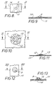
- FIGS. 8 and 9 show a variant in which the rivet 9 is mounted on a raised portion 11 similar to the bridge or leaf spring of plate 1A.
- FIGS. 10, 11 show another variant in which the rivet 9 is mounted onto an elastic tongue or dial 12 with cutout portions 13 in the side of reinforcement plate 1A.
- FIGS. 12 and 13 show another variant in which each rivet 9 slides within a hole 14 on a raised portion 15 of the reinforcement plate side 1A. On welding to the structure 5, the rivet is pushed from the welding tooling into the hole 14 to contact the structure 5.
- FIGS. 14 and 15 show a further embodiment that differs from the one of FIG. 5 in that fastening of plate 1A to the structure is obtained by a resilient tongue 16 having end portions that snap into holes 17, the latter being produced by cutting out portions from the sheet metal that constitutes the structure 5.
- FIG. 16 depicts another variant, in which plate 1A has its extreme edge 18 punched between two metal sheet elements 19, 20 welded to each other so as to constitute structure to be stiffened.
- the plate of this invention maintains every advantage of the plate described in European Patent No. 333,953, and, moreover, provides a structure stiffening the member to which it is fastened, not only where there are fastening screws, but also in areas somewhat remote from the screws without increasing the total weight of the structure.
Landscapes
- Engineering & Computer Science (AREA)
- Mechanical Engineering (AREA)
- General Engineering & Computer Science (AREA)
- Chemical & Material Sciences (AREA)
- Combustion & Propulsion (AREA)
- Transportation (AREA)
- Connection Of Plates (AREA)
Abstract
Description
- This invention concerns a plate for anchoring components on a metal sheet, including threaded sleeves obtained by stamping a part of the plate, to receive fixing screws of those components. The plate is constituted of metal having hardness from 40 to 50 Rockwell "C". The sleeves may have an enlarged end portion near the plate and an internal screw thread that is produced by rolling. Before a hardening operation on the plate, the sleeves have their extreme edge farther from the plate radially deformed by rolling, so that first turns of the thread are oval, to produce a self-locking effect.
- An anchoring plate of the general kind we are concerned with here is described and illustrated in European patent No. 333,953 owned by applicant. In many applications, particularly for the car industry, it is necessary to screw components to a sheet metal structure, typically a part of a motor vehicle body, that does not have a wall thickness that enables a screw thread to be obtained that is long enough for screws to be safely secured. In the past, this problem has been solved by employing an anchoring plate affixed to a vehicle structure. These plates had sufficient thickness to enable a screw thread to be made long enough to ensure a safe anchoring of the components, and were constituted of a relatively low hardness material to permit a self-locking bolt to be used. Due to the relatively high weight of those plates and due to the high cost of self-locking bolts, this approach was not a satisfactory solution to the problem.
- Another solution not completely satisfactory consisted in employing conventional threaded nuts (hexagonal or circular) which were spot-welded onto the sheet metal plates. A difficulty with this latter kind of anchoring plate is that the welding points may break with the possibile result that one or more nut screws in the bolt fastening may rotate.
- To avoid the disadvantages of the conventional technology described above, an anchoring plate is proposed in European patent No. 333,953. Acording to this solution, a plate is produced starting from a relatively thin rough plate of a medium hardness steel, that is treated by a progressive die to form anchoring sleeves on the plate itself. In this way sufficiently long sleeves are produced to permit shaping of an appropriate thread, without needing a relatively thick plate. The threading of each sleeve is accomplished by rolling, followed by a hardening operation, so that the finished part is lighter and more resistant than conventional plates. Furthermore, each sleeve can be rolled at its free end to ovalize the sleeve threads and produce a self-locking effect.
- FIGS. 1 and 2 of the annexed drawings are perspective views showing two opposite sides of an anchoring plate according to the invention of European Patent No. 333,953. In these figures,
numeral 1 indicates a relatively thin plate of a hard material. In particular,plate 1 is a carbon steel 1050 having a Rockwell hardness from 40 to 50.Plate 1 still can be treated by known thermic hardening procedures. Maintaining the same hardness, it is possible to have a low plate thickness and so obtain a lower weight in comparison to traditional anchoring plates. For example, a plate like the one shown in FIGS. 1 and 2 could be produced from an initial 1.6 mm. thick semi-finished product. - Next, a progressive die operation is performed on the semi-finished product producing the required
sleeves 2 extending perpendicular to the main surface of the plate. By employing a progressive die it is possible to make longer sleeves than the conventional extruded ones. In a practical application, starting from a 1.6 mm. thick plate, sleeves of 6.3 mm. have been obtained. Eachsleeve 2 has an enlargedend portion 3 near theplate 1, all sleeve parts and base plate being unitary. Inside eachsleeve 2 there is a rolled thread to receive anchor screws. Rolling the threads has the advantage that they can be formed on a thinner sleeve than is possible with a traditional threader or self-tapping screw. Also, rolling does not produce swarf that have to be removed. - After thread-forming, the
free end 4 is additionally rolled to effect ovalization on the first threads encountered by a screw entering the sleeve. This produces a self-locking effect against unscrewing. The final phase consists in a hardening treatment, so that a lighter, more resistant, more reliable part results in comparison to traditional anchoring plates and the risk of thread deterioration due to bolt screwing is avoided. - An object of the invention in one aspect is to improve anchoring plates of the European patent above mentioned, so that they can be used not only to anchor components, but also to stiffen the structure to which they are linked. To achieve this object, the invention may provide a plate for anchoring components to a sheet steel structure, the plate having stamped sleeves for receiving screws to fasten the components and the sleeves have their ends spaced from the plate radially deformed by rolling, so that the first threads are oval to achieve a self-locking effect. The plate has a complex shape, with some portions not on the same plane, made to be affixed to and conform to corresponding portions of a sheet metal structure, so that it can also contribute to the resistance of this sheet metal structure. In areas spaced from the anchoring screws, these non-coplanar portions include rivets, securable, for example by welding, to corresponding portions of the sheet metal wall structure. These corresponding portions are backward in comparison to the contact surface between the corresponding portion of the anchoring plate and the corresponding portion of the sheet metal structure, to enable the plate positioning on the sheet metal structure before welding.
- In one embodiment, the rivets are flexibly mounted in the plate so as to enable small positional adjustments. For example, rivets are placed in an elastic portion of the plate.
- In another embodiment, the rivets are carried by an elastic tongue secured to the plate. In yet another embodiment, the rivets are carried by a dial made of elastic tongues unitarily secured to the plate. In a third solution, the rivets are mounted on a raised bridgelike portion, of the plate. In another example, the rivets are slidingly located in a hole in the plate.
- In yet another embodiment, non-coplanar portions of the plate have one or more elastic tongues to snap into corresponding openings in the sheet metal structure so as to connect the plate rigidly to the structure.
- In the above mentioned embodiments, the anchoring plate of the invention, besides having characteristic functions of the plate described in the European patent, is now employed as a stiffening element for the overall structure, to increase resistance of the structure remote from the anchoring screws.
- Further characteristics and advantages of this invention will be in the following description referring to the annexed drawings given here only as a non-limiting example:
- FIGS. 1 and 2 are perspective views showing opposite sides of a plate made according to the prior art;
- FIG. 3 is a section along line 3-3 of FIG. 1;
- FIG. 4 is a schematic perspective view of a car showing a series of possible applications of this invention;
- FIG. 5 is a sectional view of a first form of accomplishment of a plate following the invention in assembled condition;
- FIGS. 6 and 7 are frontal view of a FIG. 5 plate and detail sectional view;
- FIGS. 8-9, 10-11 and 12-13 depict frontal views of three further embodiments with accompanying elevational sectional views of each;
- FIG. 14 is a sectional, elevational view of a still further plate embodiment;
- FIG. 15 is a sectional view taken along line 1515 of FIG. 14; and
- FIG. 16 is a sectional view in enlarged scale of a detail of a further variation of the plate according to the invention.
- FIGS. 1, 2 and 3 refer to the prior technology and have already been discussed.
- FIG. 4 shows a series of possible applications of reinforcement and anchoring plates made according to this invention.
Reference numeral 1A indicates a reinforcement plate made according to the invention, applied to the front and rear doors to anchor corresponding door hinges.Numeral 1B indicates anchoring plates on the body, to assemble hinge segments to the body. Numeral 1C depicts a reinforcement plate used to assemble the rear and front door striker attachments. Numeral 1D shows reinforcement plates of the invention to anchor rear and front seat belt attachments.Reinforcement plate 1E anchors hood hinge attachments and numeral 1F indicates reinforcement plates employed to anchor the front and rear bumper. Numeral 1G identifies a reinforcement plate to anchor the hood lock striker, 1H to hinge deck lid anchoring plates, and 1L and 1M anchor deck lid lock strikers. As is clearly shown by FIG. 4, the invention has a number of possible applications on the car structure, namely, wherever there is a need to anchor some components to the car body in a reliable and safe way, and, at the same time, there is a further need to stiffen the structure without increasing weight significantly. - FIG. 5 shows a first embodiment of the invention, as applied to the reinforcement plates marked as 1A in the FIG. 4 which provides anchoring of a hinge element to the car door. In FIG. 5
reference numeral 5 indicates a section of a pillar in the stamped sheet metal door structure that has a generally "U" shape, with a central side orcross arm 5A, and two integral opposing lateral sides orarms 5B and 5C. - On the interior of the door, the
pillar 5 is stiffened by theplate 1A according to the invention, which has a conforming "U" shape, with a central side or cross-arm 6 that matches the central side of the door pillar, and two integral opposing lateral sides orarms 7 and 8 that haveend portions corresponding portions 5B and 5C of the door pillar. Theplate 1A has internally directed threadedsleeves 2, formed according to the technique of FIGS. 1-3 covered by European Patent No. 333,953. These sleeves are employed for receiving screws that fix hinge door elements onto the door structure. As already mentioned, in this manner it is possible to obtain a safe anchoring between hinges and doors. As a result ofsleeves 2 axial extension, the anchor plate can be made without increasing the structure weight since the thickness of anchoringplate 1A can be relatively small. Still referring to FIG. 5, the fastening of theplate 1A to thepillar 5 is accomplished by welding rivets 9 that are carried by theanchoring plate 1A and are made of a steel which is weldable to the sheet metal of thepillar 5. - A problem arises from the condition that the plate has non-coplanar portions that have to match with corresponding portions of the structure that it is desired to stiffen. If there are differences in dimensions and construction between the
plate 1 and thepillar 5, the plate will not seat (i.e., will leave one or more gaps) within the pillar without some compensation being made. The present invention solves this problem by mounting rivets 9 on a resilient member which readily flexes to allow full mating of the plate within a receiving pillar both before and after welding. - To satisfy the above mentioned condition, each rivet 9 has according to the examples in FIGS. 6 and 7, a
resilient tongue 10 trimmed from the side ofreinforcement plate 1A in a cantilever manner and shaped to maintain the rivet 9 in contact with the opposed fitting surface of thestructure 5 portion. In that manner, the U-shaped plate can be fully positioned in the U section of thestructure 5 since thetongues 10 flex when the rivets 9 contact thesides 58 and 50. After that, rivets 9 are welded to structure 5 with a welding gun whose electrodes press each rivet against a corresponding part ofstructure 6. In this phase, thetongue 10 elasticity only permits the rivet 9 to contact with thatstructure 5 part. - FIGS. 8 and 9 show a variant in which the rivet 9 is mounted on a raised
portion 11 similar to the bridge or leaf spring ofplate 1A. - FIGS. 10, 11 show another variant in which the rivet 9 is mounted onto an elastic tongue or dial 12 with
cutout portions 13 in the side ofreinforcement plate 1A. - FIGS. 12 and 13 show another variant in which each rivet 9 slides within a
hole 14 on a raisedportion 15 of thereinforcement plate side 1A. On welding to thestructure 5, the rivet is pushed from the welding tooling into thehole 14 to contact thestructure 5. - FIGS. 14 and 15 show a further embodiment that differs from the one of FIG. 5 in that fastening of
plate 1A to the structure is obtained by aresilient tongue 16 having end portions that snap intoholes 17, the latter being produced by cutting out portions from the sheet metal that constitutes thestructure 5. - FIG. 16 depicts another variant, in which
plate 1A has itsextreme edge 18 punched between twometal sheet elements - From the above description, it is clear that the plate of this invention maintains every advantage of the plate described in European Patent No. 333,953, and, moreover, provides a structure stiffening the member to which it is fastened, not only where there are fastening screws, but also in areas somewhat remote from the screws without increasing the total weight of the structure.
- Although the invention has been described in connection with preferred embodiments, it is to be understood that those skilled in the appertaining arts may contemplate changes that come within the spirit of the described invention and within the ambit of the appended claims.
Claims (14)
- A plate to anchor components on a sheet metal structure, the plate having stamped threaded sleeves (2) for receiving screws therein, and being constructed of a steel having hardness between 40 to 50 Rockwell "Cl', the sleeves (2) having an enlarged portion (3) near the plate and a rolled internal threading, the plate having a complex shape, with non-coplanar portions (7 and 8) made to match and to be fastened to corresponding metal sheet structure portions (5B and 5C) to contribute to the resistance of this metal sheet structure in areas remote from screws, the non-coplanar portions (7 and 8) of the plate having rivets (9) for welding onto corresponding sheet metal structure portions (5B and 5C) which resiliently contact said corresponding sheet metal structure portions to enable proper positioning of the plate (1A) onto sheet metal structure (5) before welding.
- A plate according to Claim 1, characterised in that the rivets are mounted on the plate with the capability of relative movement.
- A plate according to Claim 2, characterised in that the rivets are mounted onto an elastic portion of the plate to maintain the rivet in the said structure-contacting position.
- A plate according to Claim 3, characterised in that the rivets (9) are mounted onto an elastic tongue (10) formed by trimming out from the plate (1A).
- A plate according to Claim 3, characterised in that each rivet (9) is mounted onto the central part of a dial (12) formed in the plate material by removing materials at a plurality of spaced apart locations (13) about said rivet (9).
- A plate according to Claim 3, characterised in that each rivet (9) is mounted onto a portion of the plate material (15) which is raised above the general plane of the remainder plate material.
- A plate according to Claim 2, characterised in that end portions (18) of the said plate are slidingly received within openings formed in the sheet metal structure.
- A plate according to any of Claims 1 to 7, characterised in that certain of the sleeve threads are out-of-round.
- An anchor plate for being assembled to a non-flat surface in a conformingly contacting manner, comprising:at least one means (10) resiliently unitary with the anchor plate (1A) for flexingly contacting the surface upon assembly of the plate and surface; andmeans (9) carried by the flexingly contacting means (10) for securement to the surface after the plate and surface have been assembled together.
- An anchor plate according to Claim 9, characterised in that the securement means includes a rivet (9).
- An anchor plate according to Claim 10, characterised in that the rivet (9) is welded to the surface.
- An anchor plate according to Claim 9, 10 or 11, characterised in that the flexingly contacting means includes a tongue (10) that is cantilever mounted from the plate (1A) and generally resilient in a direction transverse to the surface.
- An anchor plate according to Claim 10, characterised in that the flexingly contacting means includes a portion of said plate having adjacent plate material removed to form a leaf spring construction (11); and the rivet (9) is fixed to the leaf spring construction (11).
- Means for reinforcing a generally U-shaped weldable metal structure having a cross-arm (5A) and integral opposing side arms (5B and 5C), comprising:a metal plate (1A) having cross-arm (6) and integral opposing side arms (7 and 8) in a general U-shape of such dimensions as to enable fitting receipt within the metal structure;at least one portion (10) of said metal plate (1A) being flexible and resiliently contacting a surface of the metal structure to frictionally hold said structure and plate together in a predetermined orientation; anda rivet (9) carried by said metal plate portion welded to said metal structure maintaining the. predetermined orientation.
Applications Claiming Priority (2)
| Application Number | Priority Date | Filing Date | Title |
|---|---|---|---|
| IT94TO000819A IT1268124B1 (en) | 1994-10-17 | 1994-10-17 | ANCHORAGE PLATE |
| ITTO940819 | 1994-10-17 |
Publications (2)
| Publication Number | Publication Date |
|---|---|
| EP0708014A1 true EP0708014A1 (en) | 1996-04-24 |
| EP0708014B1 EP0708014B1 (en) | 1999-12-15 |
Family
ID=11412834
Family Applications (1)
| Application Number | Title | Priority Date | Filing Date |
|---|---|---|---|
| EP95307385A Expired - Lifetime EP0708014B1 (en) | 1994-10-17 | 1995-10-17 | Anchoring plate |
Country Status (5)
| Country | Link |
|---|---|
| US (1) | US5676510A (en) |
| EP (1) | EP0708014B1 (en) |
| DE (1) | DE69513932T2 (en) |
| ES (1) | ES2139849T3 (en) |
| IT (1) | IT1268124B1 (en) |
Cited By (5)
| Publication number | Priority date | Publication date | Assignee | Title |
|---|---|---|---|---|
| EP0856454A3 (en) * | 1997-01-31 | 2001-04-04 | DaimlerChrysler AG | Device for fixing a functional part of a self-supporting shell structure for a motor vehicle |
| EP1023198A4 (en) * | 1997-08-26 | 2004-12-01 | Hendersons Ind Pty Ltd | Seat backrest mounting |
| EP1787840A1 (en) * | 2005-11-17 | 2007-05-23 | GM Global Technology Operations, Inc. | Side door for motor vehicles |
| EP2871116A1 (en) * | 2013-11-11 | 2015-05-13 | GEDIA Gebrüder Dingerkus GmbH | Molding for motor vehicles |
| WO2020075464A1 (en) * | 2018-10-10 | 2020-04-16 | シロキ工業株式会社 | Vehicular door frame |
Families Citing this family (19)
| Publication number | Priority date | Publication date | Assignee | Title |
|---|---|---|---|---|
| AU663211B2 (en) * | 1992-09-01 | 1995-09-28 | Hirai Kosaku Kabushiki Kaisha | A screw washer |
| DE19717027C2 (en) * | 1997-04-23 | 2001-12-13 | Daimler Chrysler Ag | Screwing a hinge bracket for vehicle doors |
| SE510056C2 (en) * | 1997-08-07 | 1999-04-12 | Ssab Hardtech Ab | Ways to manufacture a hardened steel detail |
| US6644902B1 (en) * | 2000-01-11 | 2003-11-11 | E & E Manufacturing Company, Inc. | Cage-nut assembly |
| DE10351446B4 (en) * | 2003-11-04 | 2005-08-25 | Daimlerchrysler Ag | threaded plate |
| FR2877864B1 (en) * | 2004-11-16 | 2008-02-01 | Renault Sas | FIXING OF SHEET BY TAPERED FLUO TAPERED |
| US20070065249A1 (en) * | 2005-09-16 | 2007-03-22 | Anatoly Gosis | Nut plate and method of making the same |
| US7658579B1 (en) * | 2006-10-16 | 2010-02-09 | Alpha Stamping Company | Nut and retainer fastener assembly |
| KR20080092558A (en) * | 2007-04-12 | 2008-10-16 | 삼성에스디아이 주식회사 | Plasma display device and manufacturing method thereof |
| US20090283640A1 (en) * | 2008-05-15 | 2009-11-19 | The Boeing Company | Attachment system and method |
| DE102008053878B4 (en) * | 2008-10-30 | 2011-04-21 | Benteler Automobiltechnik Gmbh | Thermoforming component and method for producing a thermoformed component |
| US8899867B2 (en) * | 2011-03-02 | 2014-12-02 | Wally Wayne Tatomir | Mounting assembly for a face shield |
| US9482115B2 (en) * | 2012-08-23 | 2016-11-01 | United Technologies Corporation | Turbine engine support assembly including self anti-rotating bushing |
| DE202014008599U1 (en) * | 2014-10-29 | 2016-02-01 | GM Global Technology Operations LLC (n. d. Ges. d. Staates Delaware) | Motor vehicle door with hinge reinforcement |
| US9851048B2 (en) * | 2015-03-27 | 2017-12-26 | Altec Industries, Inc. | Liner retention system for an aerial device |
| US11266197B2 (en) | 2015-08-14 | 2022-03-08 | Wally Wayne Tatomir | Mounting assembly for a face shield with an enhanced base |
| CN105673649A (en) * | 2016-03-15 | 2016-06-15 | 李路 | Strengthening bolt for preventing rotation between steel plates |
| DE102016003810B4 (en) | 2016-03-26 | 2021-09-09 | Audi Ag | Method for connecting at least two components |
| US10661837B2 (en) * | 2017-03-30 | 2020-05-26 | Honda Motor Co., Ltd. | Door hinge standoff structure |
Citations (3)
| Publication number | Priority date | Publication date | Assignee | Title |
|---|---|---|---|---|
| US4227824A (en) * | 1977-12-09 | 1980-10-14 | Toyo Kogyo Co., Ltd. | Non-tarnishing panel edge spot welding arrangement |
| EP0333953A1 (en) | 1988-03-21 | 1989-09-27 | California Industrial Products, Inc. | Multiple sleeve-nut anchor plate |
| US5269584A (en) * | 1991-06-17 | 1993-12-14 | Nissan Motor Co., Ltd. | Reinforcement with tubular portion for receiving bolt |
Family Cites Families (4)
| Publication number | Priority date | Publication date | Assignee | Title |
|---|---|---|---|---|
| US2286982A (en) * | 1940-06-25 | 1942-06-16 | United Carr Fastener Corp | Locking nut |
| US5118234A (en) * | 1991-07-23 | 1992-06-02 | Buell Industries, Inc. | Nut plate retainer |
| US5193643A (en) * | 1991-07-25 | 1993-03-16 | Saturn Corporation | Nut and retainer assembly |
| CZ231092A3 (en) * | 1991-08-02 | 1993-02-17 | Emhart Inc | Arc welded joint between a carrier and a detail attached fixedly thereto |
-
1994
- 1994-10-17 IT IT94TO000819A patent/IT1268124B1/en active IP Right Grant
-
1995
- 1995-10-13 US US08/542,837 patent/US5676510A/en not_active Expired - Fee Related
- 1995-10-17 EP EP95307385A patent/EP0708014B1/en not_active Expired - Lifetime
- 1995-10-17 ES ES95307385T patent/ES2139849T3/en not_active Expired - Lifetime
- 1995-10-17 DE DE69513932T patent/DE69513932T2/en not_active Expired - Fee Related
Patent Citations (3)
| Publication number | Priority date | Publication date | Assignee | Title |
|---|---|---|---|---|
| US4227824A (en) * | 1977-12-09 | 1980-10-14 | Toyo Kogyo Co., Ltd. | Non-tarnishing panel edge spot welding arrangement |
| EP0333953A1 (en) | 1988-03-21 | 1989-09-27 | California Industrial Products, Inc. | Multiple sleeve-nut anchor plate |
| US5269584A (en) * | 1991-06-17 | 1993-12-14 | Nissan Motor Co., Ltd. | Reinforcement with tubular portion for receiving bolt |
Cited By (8)
| Publication number | Priority date | Publication date | Assignee | Title |
|---|---|---|---|---|
| EP0856454A3 (en) * | 1997-01-31 | 2001-04-04 | DaimlerChrysler AG | Device for fixing a functional part of a self-supporting shell structure for a motor vehicle |
| EP1023198A4 (en) * | 1997-08-26 | 2004-12-01 | Hendersons Ind Pty Ltd | Seat backrest mounting |
| EP1787840A1 (en) * | 2005-11-17 | 2007-05-23 | GM Global Technology Operations, Inc. | Side door for motor vehicles |
| US7350847B2 (en) | 2005-11-17 | 2008-04-01 | Gm Global Technology Operations, Inc. | Side door for motor vehicle |
| EP2871116A1 (en) * | 2013-11-11 | 2015-05-13 | GEDIA Gebrüder Dingerkus GmbH | Molding for motor vehicles |
| WO2020075464A1 (en) * | 2018-10-10 | 2020-04-16 | シロキ工業株式会社 | Vehicular door frame |
| JP2020059405A (en) * | 2018-10-10 | 2020-04-16 | シロキ工業株式会社 | Vehicle door frame |
| US11584202B2 (en) | 2018-10-10 | 2023-02-21 | Aisin Corporation | Vehicle door frame |
Also Published As
| Publication number | Publication date |
|---|---|
| EP0708014B1 (en) | 1999-12-15 |
| ITTO940819A1 (en) | 1996-04-17 |
| ITTO940819A0 (en) | 1994-10-17 |
| US5676510A (en) | 1997-10-14 |
| DE69513932T2 (en) | 2000-05-18 |
| DE69513932D1 (en) | 2000-01-20 |
| ES2139849T3 (en) | 2000-02-16 |
| IT1268124B1 (en) | 1997-02-20 |
Similar Documents
| Publication | Publication Date | Title |
|---|---|---|
| EP0708014B1 (en) | Anchoring plate | |
| US6146071A (en) | Caged nut assembly | |
| US5022804A (en) | Self-mounting fastener | |
| US5605353A (en) | Vehicle chassis with energy management | |
| US2443362A (en) | Fastening device | |
| EP1116890A1 (en) | Caged fastener | |
| US20040056516A1 (en) | Vehicle part mounting structure | |
| US20200248488A1 (en) | Vehicle door assembly | |
| DE3300691A1 (en) | ANCHOR PLATE ARRANGEMENT FOR A LOCKING PIN | |
| EP0096454A2 (en) | Bumper bar for a motor vehicle | |
| DE112011103977B4 (en) | Mounting assembly for mounting an inflator and vehicle occupant restraint system | |
| DE60019677T2 (en) | Adjustable mounting plate | |
| US11913261B2 (en) | Vehicle door assembly and mounting structure for a door handle | |
| US5951046A (en) | Construction for attaching a seat belt adjuster | |
| EP1395469B1 (en) | Wiper arm, in particular for a motor vehicle and a method for producing the same | |
| US2719558A (en) | Sheet metal nut with retainer means | |
| US6648291B2 (en) | Longitudinal adjusting device for a vehicle seat | |
| US20040105723A1 (en) | Attaching device for fuel tank band | |
| WO2002081259A1 (en) | Vehicle seat with bearing device | |
| DE102008041092B4 (en) | Circuit board with forming tube for guiding and supporting a drive shaft | |
| DE102010036985A1 (en) | Deformation element for use in arrangement between interior lining section and body of vehicle, is formed as one-sided open hollow profile which is fixed at inner side of interior lining section in stationary manner | |
| MXPA00003579A (en) | Caged nut assembly | |
| US4932284A (en) | Steering wheel | |
| DE102010028854A1 (en) | Pneumatic spring arrangement for use in automobile industry for cab suspension of commercial vehicle, has carrier and cover comprising respective intervention formations, which are joined with one another by radial movement | |
| US20260022724A1 (en) | Detachable Fastener Clip |
Legal Events
| Date | Code | Title | Description |
|---|---|---|---|
| PUAI | Public reference made under article 153(3) epc to a published international application that has entered the european phase |
Free format text: ORIGINAL CODE: 0009012 |
|
| AK | Designated contracting states |
Kind code of ref document: A1 Designated state(s): DE ES FR GB |
|
| 17P | Request for examination filed |
Effective date: 19960902 |
|
| 17Q | First examination report despatched |
Effective date: 19971104 |
|
| GRAG | Despatch of communication of intention to grant |
Free format text: ORIGINAL CODE: EPIDOS AGRA |
|
| GRAG | Despatch of communication of intention to grant |
Free format text: ORIGINAL CODE: EPIDOS AGRA |
|
| GRAH | Despatch of communication of intention to grant a patent |
Free format text: ORIGINAL CODE: EPIDOS IGRA |
|
| GRAH | Despatch of communication of intention to grant a patent |
Free format text: ORIGINAL CODE: EPIDOS IGRA |
|
| GRAA | (expected) grant |
Free format text: ORIGINAL CODE: 0009210 |
|
| AK | Designated contracting states |
Kind code of ref document: B1 Designated state(s): DE ES FR GB |
|
| PG25 | Lapsed in a contracting state [announced via postgrant information from national office to epo] |
Ref country code: FR Free format text: THE PATENT HAS BEEN ANNULLED BY A DECISION OF A NATIONAL AUTHORITY Effective date: 19991215 |
|
| REF | Corresponds to: |
Ref document number: 69513932 Country of ref document: DE Date of ref document: 20000120 |
|
| REG | Reference to a national code |
Ref country code: ES Ref legal event code: FG2A Ref document number: 2139849 Country of ref document: ES Kind code of ref document: T3 |
|
| ET | Fr: translation filed | ||
| PGFP | Annual fee paid to national office [announced via postgrant information from national office to epo] |
Ref country code: DE Payment date: 20001003 Year of fee payment: 6 |
|
| PGFP | Annual fee paid to national office [announced via postgrant information from national office to epo] |
Ref country code: GB Payment date: 20001004 Year of fee payment: 6 |
|
| PLBE | No opposition filed within time limit |
Free format text: ORIGINAL CODE: 0009261 |
|
| STAA | Information on the status of an ep patent application or granted ep patent |
Free format text: STATUS: NO OPPOSITION FILED WITHIN TIME LIMIT |
|
| PG25 | Lapsed in a contracting state [announced via postgrant information from national office to epo] |
Ref country code: ES Free format text: LAPSE BECAUSE OF NON-PAYMENT OF DUE FEES Effective date: 20001018 |
|
| 26N | No opposition filed | ||
| PG25 | Lapsed in a contracting state [announced via postgrant information from national office to epo] |
Ref country code: GB Free format text: LAPSE BECAUSE OF NON-PAYMENT OF DUE FEES Effective date: 20011017 |
|
| REG | Reference to a national code |
Ref country code: GB Ref legal event code: IF02 |
|
| REG | Reference to a national code |
Ref country code: FR Ref legal event code: ST |
|
| GBPC | Gb: european patent ceased through non-payment of renewal fee |
Effective date: 20011017 |
|
| PG25 | Lapsed in a contracting state [announced via postgrant information from national office to epo] |
Ref country code: DE Free format text: LAPSE BECAUSE OF NON-PAYMENT OF DUE FEES Effective date: 20020702 |
|
| REG | Reference to a national code |
Ref country code: ES Ref legal event code: FD2A Effective date: 20011113 |