EP0707860B1 - Nadelschutzvorrichtung - Google Patents
Nadelschutzvorrichtung Download PDFInfo
- Publication number
- EP0707860B1 EP0707860B1 EP95306486A EP95306486A EP0707860B1 EP 0707860 B1 EP0707860 B1 EP 0707860B1 EP 95306486 A EP95306486 A EP 95306486A EP 95306486 A EP95306486 A EP 95306486A EP 0707860 B1 EP0707860 B1 EP 0707860B1
- Authority
- EP
- European Patent Office
- Prior art keywords
- shield
- needle
- gear
- assembly
- hub
- Prior art date
- Legal status (The legal status is an assumption and is not a legal conclusion. Google has not performed a legal analysis and makes no representation as to the accuracy of the status listed.)
- Expired - Lifetime
Links
Images


Classifications
-
- A—HUMAN NECESSITIES
- A61—MEDICAL OR VETERINARY SCIENCE; HYGIENE
- A61M—DEVICES FOR INTRODUCING MEDIA INTO, OR ONTO, THE BODY; DEVICES FOR TRANSDUCING BODY MEDIA OR FOR TAKING MEDIA FROM THE BODY; DEVICES FOR PRODUCING OR ENDING SLEEP OR STUPOR
- A61M5/00—Devices for bringing media into the body in a subcutaneous, intra-vascular or intramuscular way; Accessories therefor, e.g. filling or cleaning devices, arm-rests
- A61M5/178—Syringes
- A61M5/31—Details
- A61M5/32—Needles; Details of needles pertaining to their connection with syringe or hub; Accessories for bringing the needle into, or holding the needle on, the body; Devices for protection of needles
- A61M5/3205—Apparatus for removing or disposing of used needles or syringes, e.g. containers; Means for protection against accidental injuries from used needles
- A61M5/321—Means for protection against accidental injuries by used needles
- A61M5/3216—Caps placed transversally onto the needle, e.g. pivotally attached to the needle base
-
- A—HUMAN NECESSITIES
- A61—MEDICAL OR VETERINARY SCIENCE; HYGIENE
- A61M—DEVICES FOR INTRODUCING MEDIA INTO, OR ONTO, THE BODY; DEVICES FOR TRANSDUCING BODY MEDIA OR FOR TAKING MEDIA FROM THE BODY; DEVICES FOR PRODUCING OR ENDING SLEEP OR STUPOR
- A61M5/00—Devices for bringing media into the body in a subcutaneous, intra-vascular or intramuscular way; Accessories therefor, e.g. filling or cleaning devices, arm-rests
- A61M5/178—Syringes
- A61M5/31—Details
- A61M5/32—Needles; Details of needles pertaining to their connection with syringe or hub; Accessories for bringing the needle into, or holding the needle on, the body; Devices for protection of needles
- A61M5/3202—Devices for protection of the needle before use, e.g. caps
-
- Y—GENERAL TAGGING OF NEW TECHNOLOGICAL DEVELOPMENTS; GENERAL TAGGING OF CROSS-SECTIONAL TECHNOLOGIES SPANNING OVER SEVERAL SECTIONS OF THE IPC; TECHNICAL SUBJECTS COVERED BY FORMER USPC CROSS-REFERENCE ART COLLECTIONS [XRACs] AND DIGESTS
- Y10—TECHNICAL SUBJECTS COVERED BY FORMER USPC
- Y10S—TECHNICAL SUBJECTS COVERED BY FORMER USPC CROSS-REFERENCE ART COLLECTIONS [XRACs] AND DIGESTS
- Y10S128/00—Surgery
- Y10S128/917—Body fluid, devices for protection therefrom, e.g. aids, hepatitus
- Y10S128/919—Syringe, means to protect user
Definitions
- the present invention relates to a safety shield for a needle and more particularly to a safety shield assembly which attaches to the hub of the needle, and allows use of the needle on a syringe, needle holder or other fluid handling device.
- sharp pointed needles are used for a variety of procedures.
- Devices having sharp pointed needles are used for administering fluids to patients either directly or into intravenous apparatus, and in various blood drawing applications either with syringes or with specialized holders for filling evacuated tubes.
- Hollister et al. lists 90 U.S. patents of various devices for guarding a needle as part of the background for the present shielded needle container.
- Hollister et al. discloses a stand alone adapter that has male and female ends for mating with a needle assembly and the ejection end of a syringe.
- the device of Hollister et al. includes a housing mounted to the adapter which may be pivoted to a position in alignment with the needle for enveloping the needle and locking the needle to retain it in the housing.
- the Hollister et al. device increases the unusable or "dead" volume of the device on which the adapter is mounted, requires an additional part which increases the projection of the needle hub, and the mechanism for holding the cap onto the needle snaps onto the needle itself, which may create an aerosol of any fluid remaining on the needle. Also, if bevel position is important to the intended use of the needle, the Hollister et al. invention must be carefully aligned with the needle point when mounted.
- United States Patent 5,207,653 to Janjua et al. discloses a needle cap with a longitudinal slit having a width greater than the width of a needle. According to Janjua et al., the needle cap is adapted to be pivotally connected with the needle and hub piece. Janjua et al. also discloses that the needle cap is usable with a syringe or with a needle holder for fluid collection tubes.
- the device disclosed by Janjua et al. mounts on the needle hub with a pivot, but since it only pivots in one plane, unless the needle point is precisely oriented with the hub during assembly, the shield may interfere in some applications.
- Blood drawing is one application that is particularly sensitive to needle point orientation. Most phlebotomists carefully align a needle point with the beveled face away from the skin so that the needle point placement may be precisely controlled. A needle assembly as disclosed in Janjua et al. would either sometimes be clumsy to use because the shield would sometimes be in the way or, alternatively, more expensive because of the need to carefully orient the point during assembly of the components in manufacture. Additionally, in Janjua et al., while there is a recognition of the need to secure the cap in the closed position over the needle, all of the solutions proposed require additional steps such as securing the cap with an adhesive or twisting the cap.
- EP-A-433,250 relates to a disposable syringe.
- This disposable syringe has, inside its cylinder and close to its tapered end with a fitting for the attachment of the base of an injection needle, at least one projection or relief which prevents the plunger from moving away from the needle once the plunger has nearly reached the end of the cylinder and passed the projection; this syringe also has a guard one end of which flexibly pivots about the said base and which has at least one, one-way locking element for holding the needle and which only permits the entry of the needle into the guard when the latter automatically moves into its stable position covering the needle.
- US 5,152,751 relates to a manually operated needle-shielding safety device attachable to a standard hypodermic needle and syringe medical apparatus.
- a manually operated needle-shielding safety device attachable to a standard hypodermic needle and syringe medical apparatus.
- the elongated shield is pushed from a housing mounted at the base of the hypodermic needle and syringe apparatus, rotated longitudinally from an inverted position, and advanced to the distal end of the syringe apparatus against resistance from a rubber band or integral expansion spring.
- the distal portion of the shield surmounts the tip of the needle and the needle enters the shield laterally through an opening in the shield face.
- the operator then releases thumb or finger pressure upon the pushrod and the enclosed forward end of the shield is pulled rearward by the rubber band or integral expansion spring to surround and safely contain the needle tip.
- a shielded needle assembly includes an elongate needle having a pointed distal end, a proximal end and a passageway therethrough.
- the assembly includes a hub having a proximal end, a distal end and an outside surface.
- the hub has an opening therethrough for receiving the needle so that the distal end of the needle projects outwardly.
- the hub further includes elements for releasably mounting the hub on a fluid handling device.
- the assembly includes a shield with an open end, a closed end and a sidewall with a slot extending from the open end toward the closed end.
- the shield includes an arm extending radially outwardly at the open end opposite the slot.
- the shield has a first position at which the needle is exposed for use and a second position at which the shield substantially obstructs access to the needle.
- the slot is sufficient to provide clearance for the needle.
- a mounting rotatably holds the shield onto the hub.
- the mounting includes a first pivot for pivotally attaching the shield to the mounting at the arm.
- the mounting further includes a second pivot for pivotally attaching activating elements for interacting with the arm so that movement of the activating elements about the second pivot causes movement of the shield from the first position toward the second position.
- the activating elements include a trigger positioned so that a user may cause movement of the trigger with a finger and move the shield from the first position to the second position. The shield thus locks in the second position.
- the needle projects proximally outwardly from the hub and includes a proximal point for penetrating a stopper of a fluid collection device.
- the elements for releasably mounting the hub preferably include a proximal thread for mounting the hub on a needle holder.
- the elements for releasably mounting the hub on a fluid handling device include a proximal female luer fitting which may be mounted on a syringe or other fluid handling device having a male luer fitting.
- mounting of the shield on the hub allows the shield to be rotated about the hub, thus no requirement is imposed on the manufacturing process for the assembly to orient the point. Additionally, the rotation of the mounting on the hub allows the safety needle assembly of the invention to be used on most standard fluid handling devices.
- the needle shield can easily be rotated out of the way when the needle is in use, and the trigger enables the shield to be readily moved to the second position to shield the needle without the user changing grip on the fluid handling device.
- distal refers to the direction away from a user of the invention and the term “proximal” refers to the direction toward the user.
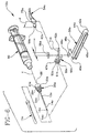
- a preferred shield needle assembly 10 of the present invention includes an elongate needle 12 having a longitudinal axis X, a pointed distal end 14, a proximal end 16 and a passageway 18 therethrough.
- the assembly includes a hub 20 with a proximal end 22, a distal end 24, an outside surface 26 having a diameter "a” and an opening 28 therethrough for receiving needle 12 so that distal end 14 projects outwardly.
- Hub 20 preferably has a circumferential groove 30 in outside surface 26 intermediate to the proximal and the distal end with an outside diameter "b" that is less than hub outside surface diameter "a”.
- Hub 20 preferably includes provisions for releasably mounting the hub on a fluid handling device.
- the fluid handling device is a needle holder 34
- hub 20 includes male threads 36 on proximal end 22 are for mounting the hub on needle holder 34.
- Needle assembly 10 preferably includes shield 38 having an open end 40, a closed end 42 and a sidewall 44 having an open slot 46 extending from open end 40 toward closed end 42. Shield 38 also includes an arm 48 extending radially outwardly at open end 40 opposite slot 46.
- the preferred assembly includes a mounting 50 for rotatably holding shield 38 onto hub 20
- Mounting 50 preferably includes a bushing 47 with an opening 51 therethrough having a sidewall 53. Sidewall 53 preferably has an inward projection 55 to mate with groove 30.
- Mounting 50 preferably includes a first pivot 49 for pivotally attaching the shield to the mounting at arm 48.
- Mounting 50 preferably further includes a second pivot 52 and a trigger 54 pivotally attached to second pivot 52 for interacting with arm 48 so that movement of the trigger about the second pivot causes movement of the shield from the first position toward the second position.
- Arm 48 preferably includes a first gear 56 with a radius "c" rotatably attached at first pivot 49 so that movement of the first gear moves shield 38 from the first position toward the second position.
- Trigger 54 includes a second gear 58 having a radius "d” meshing with first gear 56 so that movement of trigger 54 causes movement of shield 38 from the first position toward the second position.
- second gear radius "d” is greater than first gear radius "c”
- movement of the trigger about second pivot causes proportionally greater movement of the shield from the first position toward the second position.
- trigger 54 is positioned so that a user may move it with a finger.
- the preferred embodiment further includes radius "d" being about two times radius "c", with the shield first position being about 90 degrees from the shield second position about the first pivot.
- first gear 56 and second gear 58 lock shield 38 in the second position.
- first gear 56 includes a tooth 64 for locking
- second gear 58 includes a tooth 66 for locking.
- the locking teeth preferably are positioned so that locking tooth 64 and locking tooth 66 are in locking mesh when shield 38 is in the second position.
- locking tooth 64 includes a notch 68 and locking tooth 66 includes an enlarged contact surface 70 for engaging notch 68 when tooth 64 and tooth 66 are in locking mesh, thereby substantially preventing further movement of shield 38.
- Assembly 10 preferably includes proximal end 16 of needle 12 projecting proximally from hub 20 and includes a proximal point 72 useful, for example, in penetrating a resilient stopper on a fluid collection tube and the like.
- needle 12 may be formed as a single article having a proximal point on a proximal portion projecting proximally and a distal point on a distal protion projecting distally.
- needle 12 may be two separate pieces, a distal piece projecting distally having a distal point and a proximal piece projecting proximally having a proximal point, with the pieces connected in fluid communication in the hub opening.
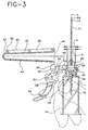
- the preferred assembly is mounted on needle holder 34 and held in a user's hand
- Shield 38 has a first position at which needle 12 is exposed
- Fig. 4 illustrates shield 38 in a second position where shield 38 substantially obstructs unintentional access to needle 12.
- Slot 46 preferably provides sufficient clearance for needle 12 when shield 38 moves from the first position to the second position.
- mounting 50 further includes a protrusion 71 adjacent second pivot 52 sized to fit within an aperture 73 in second gear 58 serving in a cam/cam follower relationship. Protrusion 71 serves to limit the range of motion of the trigger so that first gear 56 and second gear 58 remain in mesh, thereby defining the first position of the shield.
- Hub 20 further preferably includes an outward projection 74 located proximally to groove 30 on the hub outside surface. Projection 74 allows mounting 50 to rotate less than one complete revolution around hub 20, thus allowing shield 38 to be easily rotated so as not to interfere with a procedure, but also allowing assembly 10 to be dismounted by unscrewing from a needle holder for disposal.
- Hub proximal end 22 preferably includes facets 75 to facilitate removal of the assembly fluid handling device by engaging the opening of the needle disposal device.
- Assembly 10 preferably further includes a removable distal cover 76 releasably mounted on hub 20 for covering needle 12 projecting distally from the hub and a removable proximal cover 78 for covering proximal portion 16 of the needle.
- the covers 76 and 78 provide physical protection for the distal and proximal projections of the needle until the covers are removed.
- needle 12 preferably is fixedly mounted in hub 20 with an adhesive, a needle lubricant applied to the needle, then distal cover 76 and proximal cover 78 are mounted on hub 20 to protect the needle.
- distal cover 76 mounts on hub distal end 24 and has an outside diameter smaller than diameter "b", thereby allowing opening 51 to pass over the cover when mounting 50 is placed on hub 20 at groove 30.
- Preferred shield 38 includes a perimeter 80 around slot 46.
- perimeter 80 includes a raised rib 82 to substantially reduce spatter from any fluid remaining on needle 12 when a procedure is completed.
- shield 38 and mounting 50 are formed from a thermoplastic resin. Suitable resins include but are not limited to polyethylene, polycarbonate, polystyrene, polypropylene, copolymers of polyethylene and polypropylene and the like. Polypropylene, polyethylene and copolymers of polypropylene are preferred.
- the ability to rotate shield 38 about hub 20 is a particular benefit.
- the technique practiced by phlebotomists generally requires that distal point 14 be aligned so that a face 84 of distal point 14 be aligned so that face 84 is up (away from the patient).
- This bevel placement allows phlebotomist to precisely position the needle point for the puncture. The precise position allows the phlebotomist to minimize the angle of entry of the needle into the vein. A minimum penetration angle reduces the incidence of penetration of the needle through the far wall of the vein.
- assembly 10 may be configured so that shield 38 is intermediate to the first position and the second position and sealed in a package (schematically illustrated as reference number 86 in the drawings) formed from materials resistant to the passage of microorganisms and exposed to conditions that render microorganisms present in the package substantially non-viable.
- a package (schematically illustrated as reference number 86 in the drawings) formed from materials resistant to the passage of microorganisms and exposed to conditions that render microorganisms present in the package substantially non-viable.
- a package (schematically illustrated as reference number 86 in the drawings) formed from materials resistant to the passage of microorganisms and exposed to conditions that render microorganisms present in the package substantially non-viable.
- a package (schematically illustrated as reference number 86 in the drawings) formed from materials resistant to the passage of microorganisms and exposed to conditions that render microorganisms present in the package substantially non-viable.
- exposure of a packaged device to ethylene oxide or to ionizing radiation is used to
- package 86 is opened, assembly 10 removed, then proximal cover 76 is removed, the assembly mounted onto needle holder 34 using threads 36 and shield 38 moved to the first position.
- distal cover 78 is removed and the procedure is conducted as described above.
- Fig. 6 shows an alternate embodiment to the shielded assembly of Figs. 1 through 5.
- this embodiment there are elements similar in structure and function to the embodiment of the present invention shown in figs. 1 through 5. Accordingly, substantially similar components that perform substantially similar functions are numbered identically to those components of the embodiment of Figs. 1 through 5 except that a suffix "a" is added to identify those components in Fig. 6.
- needle assembly 10a includes a needle 12a having a longitudinal axis y, a pointed distal end 14a, a proximal end 16a and a passageway 18a.
- a proximal female luer fitting 88 is used for mounting the hub on a syringe 90 or any other fluid handling device having a conjugate male luer fitting.
- the needle assembly of the present invention allows the use of conventional fluid handling devices.
- the assembly permits most procedures to be performed in normal fashion with the important benefit of providing for shielding the needle without requiring any additional steps by the user other than an almost instinctive finger movement to move the shield from the first position to the second position.
Claims (10)
- Geschützte Nadelbaugruppe (10), die folgendes umfaßt:dadurch gekennzeichnet, daß die Fassung (50) ein zweites Scharnier (52) einschließt, undeine längliche Nadel (12) mit einem spitzen distalen Ende (14), einem proximalen Ende (16) und einem Durchgang (18) durch dieselbe,ein Verbindungsstück (20) mit einer Axialöffnung (28) durch dasselbe, um die Nadel (12) aufzunehmen, so daß das distale Ende (14) der Nadel aus demselben nach außen vorsteht, wobei das Verbindungsstück (20) außerdem Mittel zum lösbaren Anbringen des Verbindungsstücks an einer Fluidhandhabungsvorrichtung einschließt,einen Schutz (38), der ein offenes Ende (40), ein geschlossenes Ende (42), eine Seitenwand (44) mit einem vom offenen Ende zum geschlossenen Ende verlaufenden Schlitz (46) und einen in Radialrichtung nach außen vorstehenden Arm (48) am offenen Ende (40) gegenüber dem Schlitz (46) hat, wobei der Schutz eine erste Position hat, in der die Nadel (12) für die Benutzung freigelegt wird, und eine zweite Position hat, in welcher der Schutz (38) wesentlich den Zugang zu der Nadel (12) versperrt, wobei der Schlitz (46) ausreichend ist, um Freiraum für die Nadel (12) bereitzustellen,eine Fassung (50), um den Schutz (38) drehbar auf dem Verbindungsstück (20) zu halten, wobei die Fassung (50) ein erstes Scharnier (49) zur schwenkbaren Befestigung des Schutzes (38) mit dem Arm (48) an der Fassung (50) hat, und
durch schwenkbar an der Fassung (50) am zweiten Scharnier (52) befestigte Betätigungsmittel (54) zum Zusammenwirken mit dem Arm (48), so daß eine Bewegung der Betätigungsmittel um das zweite Scharnier (52) eine Bewegung des Schutzes (38) von der ersten Position zur zweiten Position bewirkt. - Baugruppe nach Anspruch 1, die außerdem eine abnehmbare distale Hülle (76) einschließt, die lösbar am Verbindungsstück (20) angebracht ist, um die distal vorstehende Nadel (12) zu umhüllen und physischen Schutz für dieselbe bereitzustellen, bis die distale Hülle (76) abgenommen wird.
- Baugruppe nach Anspruch 1, bei der das Mittel zum lösbaren Anbringen des Verbindungsstücks (20) an der Fluidhandhabungsvorrichtung (90) ein proximales aufnehmendes Lüer-Anschlußstück (88) umfaßt.
- Baugruppe nach Anspruch 1, bei welcher der Arm (48) außerdem ein erstes Zahnrad (56) einschließt, das drehbar am ersten Scharnier (49) befestigt ist, so daß eine Bewegung des ersten Zahnrads (56) durch dasselbe den Schutz (38) von der ersten Position zur zweiten Position bewegt, wobei das Betätigungsmittel (54) ein zweites Zahnrad (58) einschließt, das mit dem ersten Zahnrad (56) ineinandergreift, so daß eine Bewegung des Betätigungsmittels eine Bewegung des Schutzes (38) von der ersten Position zur zweiten Position bewirkt.
- Baugruppe nach Anspruch 4, bei der das erste Zahnrad (56) einen ersten Radius (c) hat und das zweite Zahnrad (58) einen zweiten Radius (d) hat, wobei der zweite Radius (d) größer ist als der erste Radius (c), so daß eine Bewegung des Betätigungsmittels (54) um das zweite Scharnier (52) eine proportional größere Bewegung des Arms (48) auf dem Schutz (38) um das erste Scharnier (49) bewirkt, wodurch eine proportional größere Bewegung des Schutzes (38) von der ersten Position zur zweiten Position bewirkt wird.
- Baugruppe nach Anspruch 5, bei welcher der Radius (d) des zweiten Zahnrades (58) etwa zweimal so groß ist wie der Radius (c) des ersten Zahnrades (56) und die erste Position des Schutzes (38) im Verhältnis zum ersten Scharnier (49) etwa neunzig Grad von der zweiten Position liegt, so daß ein Bewegen des Betätigungsmittels (54) durch einen Bogen von etwa fünfundvierzig Grad um das zweite Scharnier (52) dadurch den Schutz (38) aus der ersten Position in die zweite Position bewegt.
- Baugruppe nach Anspruch 6, bei der das erste Zahnrad (56) und das zweite Zahnrad (58) außerdem Mittel (64, 66) zum Arretieren des Schutzes (38) in der zweiten Position aufweisen.
- Baugruppe nach Anspruch 7, bei der das Mittel zum Arretieren des Schutzes (38) in der zweiten Position einschließt, daß das erste Zahnrad (56) einen Zahn (64) zum Arretieren hat und das zweite Zahnrad (58) einen Zahn (66) zum Arretieren hat, wobei die Zähne (64, 66) so positioniert sind, daß die Zähne in Sperreingriff sind, wenn sich der Schutz (38) in der zweiten Position befindet, wodurch der Schutz (38) in der zweiten Position arretiert wird.
- Baugruppe nach Anspruch 8, bei welcher der erste Zahnradsperrzahn (64) eine Kerbe (68) einschließt und der zweite Zahnradsperrzahn (66) eine vergrößerte Kontaktfläche (70) einschließt, um mit der Kerbe (68) im ersten Zahnradsperrzahn (64) ineinanderzugreifen und eine weitere Bewegung des ersten Zahnrades (56) im Verhältnis zum zweiten Zahnrad (58) wesentlich zu verhindern, wenn die Zähne (64, 66) in Sperreingriff sind.
- Baugruppe nach Anspruch 1, bei der das Betätigungsmittel einen Auslöser (54) umfaßt, der so positioniert ist, daß ein Nutzer mit einem Finger eine Bewegung des Auslösers (54) bewirken kann.
Applications Claiming Priority (2)
| Application Number | Priority Date | Filing Date | Title |
|---|---|---|---|
| US311695 | 1989-02-16 | ||
| US08/311,695 US5445619A (en) | 1994-09-23 | 1994-09-23 | Shielded needle assembly |
Publications (2)
| Publication Number | Publication Date |
|---|---|
| EP0707860A1 EP0707860A1 (de) | 1996-04-24 |
| EP0707860B1 true EP0707860B1 (de) | 2002-12-11 |
Family
ID=23208050
Family Applications (1)
| Application Number | Title | Priority Date | Filing Date |
|---|---|---|---|
| EP95306486A Expired - Lifetime EP0707860B1 (de) | 1994-09-23 | 1995-09-14 | Nadelschutzvorrichtung |
Country Status (6)
| Country | Link |
|---|---|
| US (1) | US5445619A (de) |
| EP (1) | EP0707860B1 (de) |
| JP (1) | JP2792535B2 (de) |
| CA (1) | CA2157244C (de) |
| DE (1) | DE69529140T2 (de) |
| ES (1) | ES2188640T3 (de) |
Cited By (2)
| Publication number | Priority date | Publication date | Assignee | Title |
|---|---|---|---|---|
| EP2829296A1 (de) | 2013-07-24 | 2015-01-28 | Raumedic Ag | Medizinische Injektionsvorrichtung |
| EP2829295A1 (de) | 2013-07-24 | 2015-01-28 | Raumedic Ag | Medizinische Injektionsvorrichtung |
Families Citing this family (55)
| Publication number | Priority date | Publication date | Assignee | Title |
|---|---|---|---|---|
| US5643219A (en) * | 1994-09-23 | 1997-07-01 | Burns; James A. | Shielded needle assembly |
| US5599318A (en) * | 1995-08-29 | 1997-02-04 | Becton, Dickinson And Company | Needle shield assembly having a releasable lock |
| US5651772A (en) | 1996-02-28 | 1997-07-29 | Aeroquip Corporation | Needle guard assembly |
| US5817069A (en) * | 1996-02-28 | 1998-10-06 | Vadus, Inc. | Valve assembly |
| US5704920A (en) * | 1996-05-17 | 1998-01-06 | Becton, Dickinson And Company | Manually driven needle shield assembly |
| US5913848A (en) | 1996-06-06 | 1999-06-22 | Luther Medical Products, Inc. | Hard tip over-the-needle catheter and method of manufacturing the same |
| US5913846A (en) * | 1996-06-13 | 1999-06-22 | Becton, Dickinson And Company | Shielded needle assembly |
| US5669889A (en) * | 1996-07-03 | 1997-09-23 | Becton, Dickinson And Company | Needle shield assembly having a single-use lock |
| US5725503A (en) * | 1996-08-07 | 1998-03-10 | Aeroquip Corporation | Ratcheting needle protector assembly |
| CA2261938C (en) | 1996-08-07 | 2004-07-13 | Vadus, Inc. | Needle protector |
| US5746726A (en) * | 1996-08-23 | 1998-05-05 | Becton, Dickinson And Company | Shielded needle assembly |
| US5632732A (en) * | 1996-09-11 | 1997-05-27 | Becton, Dickinson And Company | Needle assembly having single handedly activated shield |
| US5954698A (en) | 1997-01-08 | 1999-09-21 | Vadus, Inc. | Catheter apparatus having valved catheter hub and needle protector |
| US6080137A (en) | 1997-01-08 | 2000-06-27 | Vadus, Inc. | Needle protector |
| CA2221849C (en) * | 1997-03-06 | 2004-04-27 | Sandor Szabo | Single handedly releasable needle shield |
| US6120482A (en) * | 1997-09-09 | 2000-09-19 | Becton, Dickinson And Company | Pivotable guard for shielding a needle |
| EP1360970A1 (de) | 1998-08-28 | 2003-11-12 | Becton, Dickinson and Company | Methode zur Benutzung einer Schutzschild-Anordnung und daraus abgeleitete Kombination |
| US6436086B1 (en) | 1998-08-28 | 2002-08-20 | Becton Dickinson And Company | Method of using a safety shield assembly and related combinations thereof |
| US6440104B1 (en) | 1998-08-28 | 2002-08-27 | Becton, Dickinson And Company | Safety shield assembly |
| US6298541B1 (en) | 1998-08-28 | 2001-10-09 | Becton, Dickinson And Company | Method for making a safety shield assembly and related combinations thereof |
| US6837877B2 (en) * | 1999-08-23 | 2005-01-04 | Becton, Dickinson And Company | Safety shield assembly |
| US6077253A (en) * | 1999-11-15 | 2000-06-20 | Cosme; Edgar Z. | Safety needle assembly |
| US7641657B2 (en) | 2003-06-10 | 2010-01-05 | Trans1, Inc. | Method and apparatus for providing posterior or anterior trans-sacral access to spinal vertebrae |
| US6413243B1 (en) | 2000-02-21 | 2002-07-02 | Vital Signs, Inc. | Apparatus for covering a used syringe needle |
| GB2369779A (en) * | 2000-12-11 | 2002-06-12 | Tacit Technology Ltd | Hinged needle guard |
| US7890099B2 (en) | 2001-02-26 | 2011-02-15 | Kineto Wireless, Inc. | Method for automatic and seamless call transfers between a licensed wireless system and an unlicensed wireless system |
| US6695819B2 (en) | 2001-10-19 | 2004-02-24 | Terumo Medical Corporation | Safety needle assembly |
| US6984223B2 (en) | 2001-11-13 | 2006-01-10 | Becton, Dickinson And Company | Needle safety device |
| CA2422307A1 (en) * | 2002-03-20 | 2003-09-20 | Stefanie Livanos | Blood collection device |
| US6719737B2 (en) | 2002-05-13 | 2004-04-13 | Terumo Medical Corporation | Safety needle assembly |
| US7497845B2 (en) | 2002-09-13 | 2009-03-03 | Alan Reid | Needle device having slideable member providing enhanced safety |
| US7776042B2 (en) * | 2002-12-03 | 2010-08-17 | Trans1 Inc. | Methods and apparatus for provision of therapy to adjacent motion segments |
| US8231583B2 (en) * | 2002-12-04 | 2012-07-31 | Becton, Dickinson And Company | Safety needle assembly with passive pivoting shield |
| GB2398248A (en) * | 2003-02-14 | 2004-08-18 | Scient Generics Ltd | Safety device with trigger mechanism |
| WO2004110517A2 (en) * | 2003-05-28 | 2004-12-23 | Terumo Medical Corporation | Safety needle assembly |
| US8251961B2 (en) * | 2003-09-22 | 2012-08-28 | Smiths Medical Asd, Inc. | Safety needle assembly and method for making the same |
| US7272397B2 (en) | 2003-10-17 | 2007-09-18 | Kineto Wireless, Inc. | Service access control interface for an unlicensed wireless communication system |
| WO2005039651A2 (en) | 2003-10-23 | 2005-05-06 | Trans1 Inc. | Tools and tool kits for performing minimally invasive procedures on the spine |
| US8226576B2 (en) * | 2004-02-25 | 2012-07-24 | Becton, Dickinson And Company | Safety blood collection holder |
| US7648480B2 (en) * | 2005-03-31 | 2010-01-19 | Terumo Medical Corporation | Safety needle assembly |
| US7314462B2 (en) * | 2005-04-12 | 2008-01-01 | Span-America Medical Systems, Inc. | Passive needle-stick protector |
| US8844112B2 (en) * | 2005-04-18 | 2014-09-30 | Specialized Health Products, Inc. | Methods of manufacturing safety shields for medical needles and related manufacturing devices |
| JP2009526241A (ja) * | 2007-01-09 | 2009-07-16 | マリンクロット インコーポレイテッド | ニードルキャップイジェクターを備えた放射線遮蔽シリンジ |
| US8888713B2 (en) | 2007-03-07 | 2014-11-18 | Becton, Dickinson And Company | Safety blood collection assembly with indicator |
| CN105455827B (zh) | 2007-03-07 | 2019-06-18 | 贝克顿·迪金森公司 | 具有指示器的安全血液收集组件 |
| US8568365B2 (en) | 2007-05-08 | 2013-10-29 | Alan Reid | Methods and apparatus for syringe adapter |
| EP2585145B1 (de) | 2010-08-19 | 2014-03-05 | West Pharmaceutical Services, Inc. | Starrer nadelschutz |
| DE102012100971A1 (de) * | 2012-02-07 | 2013-08-08 | KD Medical GmbH Hospital Products | Sicherheitsvorrichtung für eine Kanüle |
| US9913728B2 (en) | 2013-03-14 | 2018-03-13 | Quandary Medical, Llc | Spinal implants and implantation system |
| CN105431183B (zh) * | 2013-08-07 | 2019-07-30 | 百时美施贵宝公司 | 用于与注射装置一起使用的注射辅助装置及使用方法 |
| GB201319628D0 (en) * | 2013-11-06 | 2013-12-18 | Conceptomed As | Fluid transfer devices |
| US9861784B2 (en) | 2013-12-03 | 2018-01-09 | Becton, Dickinson And Company | Blood collection device with double pivot shields |
| US20160158458A1 (en) * | 2014-12-07 | 2016-06-09 | Wuxi Yushou Medical Appliances Co., Ltd. | Safe Injection Device Capable of Locking Needle |
| US20180272074A1 (en) * | 2017-03-24 | 2018-09-27 | Te-Peng HUANG | Needle protector and syringe having the same |
| KR102267307B1 (ko) * | 2021-01-18 | 2021-06-21 | (주)풍림파마텍 | 재사용 방지구조를 갖는 주사바늘 안전보호구의 체결각도 조절장치 |
Family Cites Families (13)
| Publication number | Priority date | Publication date | Assignee | Title |
|---|---|---|---|---|
| JPS63189255U (de) * | 1987-05-29 | 1988-12-05 | ||
| JPS6417248U (de) * | 1987-07-15 | 1989-01-27 | ||
| US4966591A (en) * | 1988-10-20 | 1990-10-30 | Frank Yuen | Needle assembly |
| US4976699A (en) * | 1989-05-24 | 1990-12-11 | Gold Steven K | Needle and safety cover assembly for syringes and the like |
| CA1338657C (en) * | 1989-08-18 | 1996-10-22 | Danyl Stotland | Safety needle and cap combination device |
| EP0433250A3 (en) * | 1989-12-15 | 1992-01-22 | Ippocrate S.R.L. | Disposable syringe |
| US5067946A (en) * | 1990-04-10 | 1991-11-26 | Semen Zhadanov | Injury resistant needle device |
| US5151089A (en) * | 1990-05-16 | 1992-09-29 | Kirk Iii William D | Retractable protective needle sheath |
| US4982842A (en) | 1990-06-04 | 1991-01-08 | Concord/Portex | Safety needle container |
| US5232454A (en) * | 1990-08-01 | 1993-08-03 | Smiths Industries Medical Systems, Inc. | Safety needle container |
| US5152751A (en) * | 1990-12-04 | 1992-10-06 | Kozlowski David J | Hypodermic needle safety shield |
| AR245372A1 (es) * | 1990-12-04 | 1994-01-31 | Arcusin Sa | Capuchon de seguridad para agujas hipodermicas. |
| US5242417A (en) * | 1992-01-13 | 1993-09-07 | Paudler Gary M | Self closing hinged syringe guard |
-
1994
- 1994-09-23 US US08/311,695 patent/US5445619A/en not_active Expired - Fee Related
-
1995
- 1995-08-30 CA CA002157244A patent/CA2157244C/en not_active Expired - Fee Related
- 1995-09-14 ES ES95306486T patent/ES2188640T3/es not_active Expired - Lifetime
- 1995-09-14 EP EP95306486A patent/EP0707860B1/de not_active Expired - Lifetime
- 1995-09-14 DE DE69529140T patent/DE69529140T2/de not_active Expired - Lifetime
- 1995-09-21 JP JP7242802A patent/JP2792535B2/ja not_active Expired - Fee Related
Cited By (5)
| Publication number | Priority date | Publication date | Assignee | Title |
|---|---|---|---|---|
| EP2829296A1 (de) | 2013-07-24 | 2015-01-28 | Raumedic Ag | Medizinische Injektionsvorrichtung |
| EP2829295A1 (de) | 2013-07-24 | 2015-01-28 | Raumedic Ag | Medizinische Injektionsvorrichtung |
| DE102013214442A1 (de) | 2013-07-24 | 2015-01-29 | Raumedic Ag | Medizinische Injektionsvorrichtung |
| DE102013214429A1 (de) | 2013-07-24 | 2015-02-19 | Raumedic Ag | Medizinische Injektionsvorrichtung |
| US10279122B2 (en) | 2013-07-24 | 2019-05-07 | Raumedic Ag | Medical injection device |
Also Published As
| Publication number | Publication date |
|---|---|
| CA2157244C (en) | 1999-01-19 |
| DE69529140T2 (de) | 2003-10-09 |
| ES2188640T3 (es) | 2003-07-01 |
| EP0707860A1 (de) | 1996-04-24 |
| JPH08103497A (ja) | 1996-04-23 |
| DE69529140D1 (de) | 2003-01-23 |
| US5445619A (en) | 1995-08-29 |
| JP2792535B2 (ja) | 1998-09-03 |
| CA2157244A1 (en) | 1996-03-24 |
Similar Documents
| Publication | Publication Date | Title |
|---|---|---|
| EP0707860B1 (de) | Nadelschutzvorrichtung | |
| EP0832660B1 (de) | Nadelschutzvorrichtung | |
| US5643219A (en) | Shielded needle assembly | |
| US5868716A (en) | Shielded needle assembly | |
| EP0812597B1 (de) | Nadelschutzvorrichtung | |
| EP0885621B1 (de) | Schwenkbare Nadelschutzvorrichtung | |
| EP1346741B1 (de) | Abdeckbare Nadelvorrichtung mit angedrücktem Sicherheitsschutz | |
| AU2007249578C1 (en) | Blood collection device with needle container means | |
| US5632732A (en) | Needle assembly having single handedly activated shield | |
| CN105268083B (zh) | 被动防护针装置 | |
| MXPA97006432A (en) | Blind needle assembly | |
| US20020161336A1 (en) | Needle shield assembly | |
| MXPA97006864A (en) | Ag protected assembly |
Legal Events
| Date | Code | Title | Description |
|---|---|---|---|
| PUAI | Public reference made under article 153(3) epc to a published international application that has entered the european phase |
Free format text: ORIGINAL CODE: 0009012 |
|
| AK | Designated contracting states |
Kind code of ref document: A1 Designated state(s): DE ES FR GB IT |
|
| 17P | Request for examination filed |
Effective date: 19961018 |
|
| 17Q | First examination report despatched |
Effective date: 20010531 |
|
| GRAG | Despatch of communication of intention to grant |
Free format text: ORIGINAL CODE: EPIDOS AGRA |
|
| GRAG | Despatch of communication of intention to grant |
Free format text: ORIGINAL CODE: EPIDOS AGRA |
|
| GRAH | Despatch of communication of intention to grant a patent |
Free format text: ORIGINAL CODE: EPIDOS IGRA |
|
| GRAH | Despatch of communication of intention to grant a patent |
Free format text: ORIGINAL CODE: EPIDOS IGRA |
|
| GRAA | (expected) grant |
Free format text: ORIGINAL CODE: 0009210 |
|
| AK | Designated contracting states |
Kind code of ref document: B1 Designated state(s): DE ES FR GB IT |
|
| REG | Reference to a national code |
Ref country code: GB Ref legal event code: FG4D |
|
| REF | Corresponds to: |
Ref document number: 69529140 Country of ref document: DE Date of ref document: 20030123 |
|
| ET | Fr: translation filed | ||
| REG | Reference to a national code |
Ref country code: ES Ref legal event code: FG2A Ref document number: 2188640 Country of ref document: ES Kind code of ref document: T3 |
|
| PLBE | No opposition filed within time limit |
Free format text: ORIGINAL CODE: 0009261 |
|
| STAA | Information on the status of an ep patent application or granted ep patent |
Free format text: STATUS: NO OPPOSITION FILED WITHIN TIME LIMIT |
|
| 26N | No opposition filed |
Effective date: 20030912 |
|
| PGFP | Annual fee paid to national office [announced via postgrant information from national office to epo] |
Ref country code: ES Payment date: 20050927 Year of fee payment: 11 |
|
| PGFP | Annual fee paid to national office [announced via postgrant information from national office to epo] |
Ref country code: IT Payment date: 20060930 Year of fee payment: 12 |
|
| REG | Reference to a national code |
Ref country code: ES Ref legal event code: FD2A Effective date: 20060915 |
|
| PG25 | Lapsed in a contracting state [announced via postgrant information from national office to epo] |
Ref country code: ES Free format text: LAPSE BECAUSE OF NON-PAYMENT OF DUE FEES Effective date: 20060915 |
|
| PGFP | Annual fee paid to national office [announced via postgrant information from national office to epo] |
Ref country code: FR Payment date: 20070917 Year of fee payment: 13 |
|
| REG | Reference to a national code |
Ref country code: FR Ref legal event code: ST Effective date: 20090529 |
|
| PG25 | Lapsed in a contracting state [announced via postgrant information from national office to epo] |
Ref country code: IT Free format text: LAPSE BECAUSE OF NON-PAYMENT OF DUE FEES Effective date: 20070914 |
|
| PG25 | Lapsed in a contracting state [announced via postgrant information from national office to epo] |
Ref country code: FR Free format text: LAPSE BECAUSE OF NON-PAYMENT OF DUE FEES Effective date: 20080930 |
|
| PGFP | Annual fee paid to national office [announced via postgrant information from national office to epo] |
Ref country code: GB Payment date: 20120925 Year of fee payment: 18 |
|
| PGFP | Annual fee paid to national office [announced via postgrant information from national office to epo] |
Ref country code: DE Payment date: 20120927 Year of fee payment: 18 |
|
| GBPC | Gb: european patent ceased through non-payment of renewal fee |
Effective date: 20130914 |
|
| REG | Reference to a national code |
Ref country code: DE Ref legal event code: R119 Ref document number: 69529140 Country of ref document: DE Effective date: 20140401 |
|
| PG25 | Lapsed in a contracting state [announced via postgrant information from national office to epo] |
Ref country code: GB Free format text: LAPSE BECAUSE OF NON-PAYMENT OF DUE FEES Effective date: 20130914 |
|
| PG25 | Lapsed in a contracting state [announced via postgrant information from national office to epo] |
Ref country code: DE Free format text: LAPSE BECAUSE OF NON-PAYMENT OF DUE FEES Effective date: 20140401 |