EP0707291A2 - Abgabesystem für Verkaufsautomat - Google Patents
Abgabesystem für Verkaufsautomat Download PDFInfo
- Publication number
- EP0707291A2 EP0707291A2 EP95307292A EP95307292A EP0707291A2 EP 0707291 A2 EP0707291 A2 EP 0707291A2 EP 95307292 A EP95307292 A EP 95307292A EP 95307292 A EP95307292 A EP 95307292A EP 0707291 A2 EP0707291 A2 EP 0707291A2
- Authority
- EP
- European Patent Office
- Prior art keywords
- relation
- vending machine
- dispensing system
- stop means
- turnstile
- Prior art date
- Legal status (The legal status is an assumption and is not a legal conclusion. Google has not performed a legal analysis and makes no representation as to the accuracy of the status listed.)
- Granted
Links
- 125000006850 spacer group Chemical group 0.000 claims description 4
- 230000000903 blocking effect Effects 0.000 claims description 2
- 238000006243 chemical reaction Methods 0.000 description 3
- 235000013361 beverage Nutrition 0.000 description 2
- 230000000994 depressogenic effect Effects 0.000 description 1
- 230000000694 effects Effects 0.000 description 1
- 238000004519 manufacturing process Methods 0.000 description 1
- 230000008707 rearrangement Effects 0.000 description 1
Images


Classifications
-
- G—PHYSICS
- G07—CHECKING-DEVICES
- G07F—COIN-FREED OR LIKE APPARATUS
- G07F11/00—Coin-freed apparatus for dispensing, or the like, discrete articles
- G07F11/02—Coin-freed apparatus for dispensing, or the like, discrete articles from non-movable magazines
- G07F11/04—Coin-freed apparatus for dispensing, or the like, discrete articles from non-movable magazines in which magazines the articles are stored one vertically above the other
- G07F11/16—Delivery means
- G07F11/24—Rotary or oscillatory members
Definitions
- This invention relates generally to vending machines and particularly to a dispensing system which provides for the dispensing of articles of different size from the same storage compartment.
- Vending machines are well known which dispense articles, such as cans, from storage compartments.
- US-A-4,991,739 and US-A-4,991,740 disclose vending machines for dispensing cans from compartments having a turnstile type support below each compartment which dispenses cans of a particular size, the compartments being suitable for storing a depth of one or more cans.
- the turnstile support is activated by a reciprocating release mechanism and works well for its intended purpose.
- the present invention aims to solve these and other problems in a manner not revealed in the known prior art.
- the invention provides a vending machine dispensing system which can be readily converted from continuously dispensing containers of one size to continuously dispensing containers of a different size.
- This dispensing system has the particular advantage that the conversion can be readily made at the vending machine site since the conversion mechanism is self-contained and no additional parts are necessary nor is any shimming required.
- the vending machine dispensing system can be used with systems dispensing containers from multiple depth compartments so that a system dispensing two small cans stored end-to-end can readily be converted to dispense a single larger bottle.
- the spacing between the turnstile means and the stop means is adjustable to determine the diameter of the article passing between said turnstile and said stop means.
- the storage compartment includes opposed end walls, the turnstile means is mounted for rotation about a fixed axis transverse to said end walls, and the stop means is disposed in spaced parallel relation to said fixed axis and includes means mounting said stop means in adjustable relation to said end walls to change said spacing.
- said stop means includes an arcuate member
- said mounting means includes an upper and lower elongate member extending between said end walls in parallel relation to said turnstile fixed axis, and upper and lower adjustment means on said stop means receiving said arcuate member in adjustable relation.
- said adjustment means includes an upper slot-shaped opening receiving said upper elongate member in sliding relation and a pair of lower openings, one of said lower openings receiving said lower elongate member in sliding relation to determine the relative position of the stop means.
- one of said end walls includes movable latch means preventing inadvertent removal of said removable member and another aspect to provide that said latch means includes a pair of vertical slots disposed in one of said end walls adjacent an end of said removable elongate member and a U-shaped member mounted in said slots and movable from a position blocking said end of said removable member to a position clearing said end of said movable member.
- the storage compartment includes first and second portions adapted to receive two articles of the same diameter in end-to-end relation.
- the storage compartment includes opposed end walls and first and second compartment portions adapted to receive two articles of the same diameter in end-to-end relation
- the turnstile means is mounted for rotation about a fixed axis transverse to said end walls
- the stop means is disposed in spaced parallel relation to said fixed axis and includes means adjustably mounting said stop means in adjustable relation to said end walls to change said spaced parallel relation
- a second stop means is disposed on the other side of the exit passage in spaced end relation from said spaced stop means and in fixed spaced relation from the turnstile means to provide an escrow means for one of said same diameter articles.
- said stop means includes an arcuate member
- said mounting means includes an upper and lower elongate member extending between said end walls in parallel relation to said fixed axis and upper and lower adjustment means on said stop means receiving said arcuate member in adjustable relation
- said second stop means is mounted in fixed position on said upper and lower elongate members.
- said second stop means includes an arcuate member and upper and lower openings receiving said upper and lower elongate members in sliding relation.
- This vending machine dispensing system is inexpensive to manufacture and the conversion can be effectuated by an operator without special skills and the system is very effective for its intended purpose.
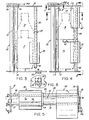
- the dispensing assembly 10 is suitable for a vending machine such as that described in US-A-4,991,739, which is incorporated herein by reference. Similar to US-A-4,991,739 the vending machine herein includes a plurality of compartments disposed in side-by-side relation each having a turnstile support means and stop means and a release means which may be a chain-operated ratchet and pawl assembly. However, for the purposes herein only one compartment indicated by numeral 1 will be described.
- the compartment 1 includes opposed sidewalls 12 and 14 providing guide means for articles such as containers A which are, for example, 10 ounce bottles.
- the compartment is further defined by end walls 16 and 18 and, at the lower end of the compartment 1, a turnstile support member 20 and a stop member 30 are provided.
- the turnstile member 20 has a three-point star configuration and is supported between the compartment end walls 16 and 18 for rotation about a fixed axis 22.
- the stop member 30 is disposed in selectively spaced relation from the fixed axis of rotation 22.
- the spacing of the stop member from the turnstile member 20 is adjustable, and in the embodiment shown, the adjustment is achieved by the mounting arrangement of the stop member which consists essentially of lower and upper elongate members in the form of rods 32 and 34.
- the rods 32 and 34 have fixed axes disposed in spaced parallel relation from the fixed turnstile member axis 22.
- the stop member 30 is in the form of a molded body having an arcuate front face 36 and transverse ribs 38 and 40.
- the arcuate front face 36 is disposed at a distance S1 from the arcuate face of the turnstile member 20.
- upper rib 40 includes a slot-shaped opening 42 passing through the rib and receiving the rod 34 in sliding relation
- lower rib 38 includes a pair of circular openings 44 and 46.
- the lower rod 32 is shown in opening 44 but each opening is adapted to receive the lower rod 32 in sliding relation to adjust the position of the stop member.
- the inclination of the slot-shaped upper opening 42 and the inclination of intersection line between the axes of openings 44 and 46 is substantially the same and provides a structural arrangement by which the arcuate stop member 30 can be readily moved to a different distance S2 and provide a greater gap between turnstile member 20 and stop member 30 which will permit passage of a larger diameter container B .
- This repositioning is achieved by removing the lower rod 34 and relocating the stop member 30, so that the upper rod 34 is located relatively at the other end of the slot-shaped opening 42, and then inserting the lower rod 32 in the other opening 46.
- the rearrangement is shown in FIG. 2 and, in effect, widens the exit passage to receive a container B , such as a 20 ounce bottle of a greater diameter.
- the upper rod 34 which is not removed, is provided with spacers 48 and 50.
- the lower rod 32 which is removed and replaced, is provided with a U-shaped latch member 52 which is snapped into place and is slidably mounted in cooperating slots 54.
- the latch member 52 can very easily be raised to clear the end of rod 32 to effectuate removal of the rod.
- FIG. 4 shows a compartment 1 divided into two portions 1a and 1b each receiving a container C , such as a 12 ounce can.
- the cans C are close to the same diameter as the container A but are of a sufficiently shorter length to permit two cans C to be placed end-to-end in the compartment 1.
- This arrangement requires the provision of an escrow member 60, which is best shown in FIG. 6 and is in the form of a molded body having an arcuate front face 62 and lower and upper transverse ribs 64 and 66.
- the arcuate face is disposed at a distance S1 from the arcuate face of the turnstile member 20.
- the ribs 64 and 66 each includes a circular opening 65 and 67, respectively, slidably receiving the rods 32 and 34, respectively, so that the escrow member 60 is mounted in fixed relation on the rods relative to the turnstile member 20.
- a spacer 49 is provided on the upper rod 34 between the stop member and the escrow member 60, which maintains the stop member 30 and the escrow member 60 in position longitudinally. This arrangement provides that when the lower rod 32 is removed to change the disposition of the stop member 30, the disposition of the escrow member is unaffected. It will be understood that the escrow member 60 performs an escrow function only when the compartment is used for a double dispensing function.
- the release mechanism consists of a ratchet and pawl assembly.
- the ratchet wheel 70 is fixedly connected to the end of the turnstile member 20, which tends to rotate under the weight of a container and the wheel 70 is held against rotation by a pivoted escapement pawl 80.
- the spring-biased pawl 80 is actuated as by an indexing member 94 carried by reciprocating chain 100.
- an anti-tilt feature may be provided in the form of a leaf spring 68 which is mounted to the upper and lower rods 32 and 34 and extends into the area occupied by container Cb .
- the spring is normally depressed by the weight of the container Cb .
- the spring 68 prevents longitudinal movement of container Ca when the machine is tilted by vandals.
- the turnstile member 20 rotates about a rod having a fixed axis of rotation 22.
- the stop member 30 is carried by lower and upper rods 32 and 34, which have fixed axes disposed in spaced parallel relation from the fixed axis of rotation indicated by numeral 22 of the rod carrying the turnstile member 20.
- the inclined upper slot-shaped opening 42 receiving the rod 34, and the pair of openings 44 and 46 disposed in inclined relation to each other, provide that when the rod 32 is received within opening 44 the stop member 30 takes up a first position. In this first position, container A can pass between the turnstile member 20 and the stop member 30.
Landscapes
- Physics & Mathematics (AREA)
- General Physics & Mathematics (AREA)
- Vending Machines For Individual Products (AREA)
- De-Stacking Of Articles (AREA)
Applications Claiming Priority (2)
| Application Number | Priority Date | Filing Date | Title |
|---|---|---|---|
| US08/323,363 US5511688A (en) | 1994-10-14 | 1994-10-14 | Vending machine dispensing system |
| US323363 | 1999-06-01 |
Publications (3)
| Publication Number | Publication Date |
|---|---|
| EP0707291A2 true EP0707291A2 (de) | 1996-04-17 |
| EP0707291A3 EP0707291A3 (de) | 1996-09-04 |
| EP0707291B1 EP0707291B1 (de) | 1998-12-16 |
Family
ID=23258894
Family Applications (1)
| Application Number | Title | Priority Date | Filing Date |
|---|---|---|---|
| EP95307292A Expired - Lifetime EP0707291B1 (de) | 1994-10-14 | 1995-10-13 | Abgabesystem für Verkaufsautomat |
Country Status (7)
| Country | Link |
|---|---|
| US (1) | US5511688A (de) |
| EP (1) | EP0707291B1 (de) |
| BR (1) | BR9504391A (de) |
| CA (1) | CA2159793C (de) |
| DE (1) | DE69506662T2 (de) |
| ES (1) | ES2127478T3 (de) |
| MX (1) | MX9504345A (de) |
Cited By (2)
| Publication number | Priority date | Publication date | Assignee | Title |
|---|---|---|---|---|
| EP0801366A3 (de) * | 1996-04-09 | 1999-01-13 | ROYAL VENDORS, Inc. | Einstellbarer Verkaufsmechanismus |
| WO1999041716A1 (en) * | 1998-02-12 | 1999-08-19 | Nida Group Pty. Ltd. | Dispensing means for vending machine |
Families Citing this family (5)
| Publication number | Priority date | Publication date | Assignee | Title |
|---|---|---|---|---|
| AU2001282715A1 (en) * | 2000-07-31 | 2002-02-13 | Caltex New Zealand Limited | A dispensing apparatus |
| US20040112709A1 (en) * | 2002-12-12 | 2004-06-17 | Yang Ping Jan | Coin-operated cabinet lock |
| US7784644B2 (en) * | 2005-10-14 | 2010-08-31 | Dixie-Narco, Inc. | Tandem gate release mechanism for a vending machine |
| JP4933126B2 (ja) * | 2006-03-31 | 2012-05-16 | 株式会社システムコミュニケーションズ | 商品陳列トレイ装置及び移動ガイド手段 |
| CN103903350A (zh) * | 2012-12-28 | 2014-07-02 | 鸿富锦精密工业(深圳)有限公司 | 自动售货机出货机构 |
Citations (2)
| Publication number | Priority date | Publication date | Assignee | Title |
|---|---|---|---|---|
| US4991740A (en) | 1988-08-10 | 1991-02-12 | Coin Acceptors, Inc. | Vending machine |
| US4991739A (en) | 1988-08-10 | 1991-02-12 | Coin Acceptors, Inc. | Vending machine |
Family Cites Families (7)
| Publication number | Priority date | Publication date | Assignee | Title |
|---|---|---|---|---|
| US2785828A (en) * | 1952-10-24 | 1957-03-19 | Seth B Atwood | Dispensing machine |
| US2836326A (en) * | 1955-02-21 | 1958-05-27 | Vendo Co | Magazine for the storage of articles |
| US3362582A (en) * | 1965-04-28 | 1968-01-09 | Westinghouse Electric Corp | Vending machine with separately acting, series, article releasers |
| US3361505A (en) * | 1966-05-24 | 1968-01-02 | Westinghouse Electric Corp | Vending machine |
| DE3820690C1 (en) * | 1988-06-18 | 1989-06-22 | Sielaff Gmbh & Co Automatenbau Herrieden, 8808 Herrieden, De | Dispensing device for a pair of shafts of a vending machine |
| US4940161A (en) * | 1988-06-28 | 1990-07-10 | The Vendo Company | Ramp apparatus |
| US4986615A (en) * | 1988-10-17 | 1991-01-22 | The Vendo Company | Vending apparatus |
-
1994
- 1994-10-14 US US08/323,363 patent/US5511688A/en not_active Expired - Lifetime
-
1995
- 1995-10-03 CA CA002159793A patent/CA2159793C/en not_active Expired - Fee Related
- 1995-10-11 BR BR9504391A patent/BR9504391A/pt not_active IP Right Cessation
- 1995-10-13 ES ES95307292T patent/ES2127478T3/es not_active Expired - Lifetime
- 1995-10-13 MX MX9504345A patent/MX9504345A/es unknown
- 1995-10-13 DE DE69506662T patent/DE69506662T2/de not_active Expired - Fee Related
- 1995-10-13 EP EP95307292A patent/EP0707291B1/de not_active Expired - Lifetime
Patent Citations (2)
| Publication number | Priority date | Publication date | Assignee | Title |
|---|---|---|---|---|
| US4991740A (en) | 1988-08-10 | 1991-02-12 | Coin Acceptors, Inc. | Vending machine |
| US4991739A (en) | 1988-08-10 | 1991-02-12 | Coin Acceptors, Inc. | Vending machine |
Cited By (3)
| Publication number | Priority date | Publication date | Assignee | Title |
|---|---|---|---|---|
| EP0801366A3 (de) * | 1996-04-09 | 1999-01-13 | ROYAL VENDORS, Inc. | Einstellbarer Verkaufsmechanismus |
| WO1999041716A1 (en) * | 1998-02-12 | 1999-08-19 | Nida Group Pty. Ltd. | Dispensing means for vending machine |
| US6431398B1 (en) | 1998-02-12 | 2002-08-13 | Nida Group Pty Ltd | Dispensing mean for vending machine |
Also Published As
| Publication number | Publication date |
|---|---|
| US5511688A (en) | 1996-04-30 |
| EP0707291A3 (de) | 1996-09-04 |
| ES2127478T3 (es) | 1999-04-16 |
| EP0707291B1 (de) | 1998-12-16 |
| DE69506662T2 (de) | 1999-06-24 |
| CA2159793A1 (en) | 1996-04-15 |
| BR9504391A (pt) | 1997-05-27 |
| CA2159793C (en) | 2001-12-25 |
| AU701832B2 (en) | 1999-02-04 |
| MX9504345A (es) | 1997-03-29 |
| AU3305495A (en) | 1996-05-02 |
| DE69506662D1 (de) | 1999-01-28 |
Similar Documents
| Publication | Publication Date | Title |
|---|---|---|
| AU706983B2 (en) | Adjustable retainer system for vending machine storage compartments | |
| US5996838A (en) | Vending machine | |
| AU715602B1 (en) | Vending machine for bottles | |
| EP1114634A3 (de) | Abfüllgerät für Medikamente | |
| US5261564A (en) | Drum-type vending machine | |
| EP0707291B1 (de) | Abgabesystem für Verkaufsautomat | |
| US4298138A (en) | Tandem column vender apparatus | |
| US6206234B1 (en) | Cigar vending machine | |
| US4763963A (en) | Skewed serpentine multi-package product storage rack | |
| US4509658A (en) | Anti-theft device for tandem column vendor | |
| US5472074A (en) | Coin operated dispensing machine | |
| CA1211417A (en) | Dispensing mechanism for vending machines or the like | |
| CA1192168A (en) | Plural mode multi-column dispensing machine | |
| US6431398B1 (en) | Dispensing mean for vending machine | |
| US6149031A (en) | Beverage dispensing machine and method of operation thereof | |
| CA2200033C (en) | Adjustable vending mechanism | |
| US20030150870A1 (en) | Universal vending machine | |
| US5611527A (en) | Device for dispensing a sheetlike object from a stack | |
| US20030146238A1 (en) | Vending machine for dispensing cans & bottles with elevator assembly | |
| AU765311B2 (en) | Dispensing means for vending machine | |
| US3454193A (en) | Convertible baffle support unit for staggered stack bottle or can vender | |
| HU214753B (hu) | Poháradagoló italautomatához | |
| EP1133761B1 (de) | Zigarrenverkaufsautomat | |
| CZ288455B6 (en) | Vending machine for dispensing packaged articles, particularly beverages | |
| CZ9801U1 (en) | Packed products - especially drinks - vending machine |
Legal Events
| Date | Code | Title | Description |
|---|---|---|---|
| PUAI | Public reference made under article 153(3) epc to a published international application that has entered the european phase |
Free format text: ORIGINAL CODE: 0009012 |
|
| AK | Designated contracting states |
Kind code of ref document: A2 Designated state(s): DE ES FR GB IT |
|
| PUAL | Search report despatched |
Free format text: ORIGINAL CODE: 0009013 |
|
| AK | Designated contracting states |
Kind code of ref document: A3 Designated state(s): DE ES FR GB IT |
|
| 17P | Request for examination filed |
Effective date: 19961028 |
|
| 17Q | First examination report despatched |
Effective date: 19970701 |
|
| GRAG | Despatch of communication of intention to grant |
Free format text: ORIGINAL CODE: EPIDOS AGRA |
|
| GRAG | Despatch of communication of intention to grant |
Free format text: ORIGINAL CODE: EPIDOS AGRA |
|
| GRAH | Despatch of communication of intention to grant a patent |
Free format text: ORIGINAL CODE: EPIDOS IGRA |
|
| GRAH | Despatch of communication of intention to grant a patent |
Free format text: ORIGINAL CODE: EPIDOS IGRA |
|
| GRAA | (expected) grant |
Free format text: ORIGINAL CODE: 0009210 |
|
| AK | Designated contracting states |
Kind code of ref document: B1 Designated state(s): DE ES FR GB IT |
|
| ITF | It: translation for a ep patent filed | ||
| REF | Corresponds to: |
Ref document number: 69506662 Country of ref document: DE Date of ref document: 19990128 |
|
| ET | Fr: translation filed | ||
| REG | Reference to a national code |
Ref country code: ES Ref legal event code: FG2A Ref document number: 2127478 Country of ref document: ES Kind code of ref document: T3 |
|
| PLBE | No opposition filed within time limit |
Free format text: ORIGINAL CODE: 0009261 |
|
| STAA | Information on the status of an ep patent application or granted ep patent |
Free format text: STATUS: NO OPPOSITION FILED WITHIN TIME LIMIT |
|
| 26N | No opposition filed | ||
| REG | Reference to a national code |
Ref country code: GB Ref legal event code: IF02 |
|
| PGFP | Annual fee paid to national office [announced via postgrant information from national office to epo] |
Ref country code: DE Payment date: 20041007 Year of fee payment: 10 |
|
| PGFP | Annual fee paid to national office [announced via postgrant information from national office to epo] |
Ref country code: FR Payment date: 20041008 Year of fee payment: 10 |
|
| PGFP | Annual fee paid to national office [announced via postgrant information from national office to epo] |
Ref country code: GB Payment date: 20041013 Year of fee payment: 10 |
|
| PGFP | Annual fee paid to national office [announced via postgrant information from national office to epo] |
Ref country code: ES Payment date: 20041116 Year of fee payment: 10 |
|
| PG25 | Lapsed in a contracting state [announced via postgrant information from national office to epo] |
Ref country code: IT Free format text: LAPSE BECAUSE OF NON-PAYMENT OF DUE FEES Effective date: 20051013 Ref country code: GB Free format text: LAPSE BECAUSE OF NON-PAYMENT OF DUE FEES Effective date: 20051013 |
|
| PG25 | Lapsed in a contracting state [announced via postgrant information from national office to epo] |
Ref country code: ES Free format text: LAPSE BECAUSE OF NON-PAYMENT OF DUE FEES Effective date: 20051014 |
|
| PG25 | Lapsed in a contracting state [announced via postgrant information from national office to epo] |
Ref country code: DE Free format text: LAPSE BECAUSE OF NON-PAYMENT OF DUE FEES Effective date: 20060503 |
|
| GBPC | Gb: european patent ceased through non-payment of renewal fee |
Effective date: 20051013 |
|
| PG25 | Lapsed in a contracting state [announced via postgrant information from national office to epo] |
Ref country code: FR Free format text: LAPSE BECAUSE OF NON-PAYMENT OF DUE FEES Effective date: 20060630 |
|
| REG | Reference to a national code |
Ref country code: FR Ref legal event code: ST Effective date: 20060630 |
|
| REG | Reference to a national code |
Ref country code: ES Ref legal event code: FD2A Effective date: 20051014 |