EP0706936B1 - Perfectionnements aux dispositifs de commande de pas pour rotors sans articulation - Google Patents
Perfectionnements aux dispositifs de commande de pas pour rotors sans articulation Download PDFInfo
- Publication number
- EP0706936B1 EP0706936B1 EP95402239A EP95402239A EP0706936B1 EP 0706936 B1 EP0706936 B1 EP 0706936B1 EP 95402239 A EP95402239 A EP 95402239A EP 95402239 A EP95402239 A EP 95402239A EP 0706936 B1 EP0706936 B1 EP 0706936B1
- Authority
- EP
- European Patent Office
- Prior art keywords
- pitch
- rotor
- blade
- axis
- articulated
- Prior art date
- Legal status (The legal status is an assumption and is not a legal conclusion. Google has not performed a legal analysis and makes no representation as to the accuracy of the status listed.)
- Expired - Lifetime
Links
Images
Classifications
-
- B—PERFORMING OPERATIONS; TRANSPORTING
- B64—AIRCRAFT; AVIATION; COSMONAUTICS
- B64C—AEROPLANES; HELICOPTERS
- B64C27/00—Rotorcraft; Rotors peculiar thereto
- B64C27/32—Rotors
- B64C27/46—Blades
- B64C27/473—Constructional features
- B64C27/48—Root attachment to rotor head
-
- B—PERFORMING OPERATIONS; TRANSPORTING
- B64—AIRCRAFT; AVIATION; COSMONAUTICS
- B64C—AEROPLANES; HELICOPTERS
- B64C27/00—Rotorcraft; Rotors peculiar thereto
- B64C27/51—Damping of blade movements
-
- B—PERFORMING OPERATIONS; TRANSPORTING
- B64—AIRCRAFT; AVIATION; COSMONAUTICS
- B64C—AEROPLANES; HELICOPTERS
- B64C27/00—Rotorcraft; Rotors peculiar thereto
- B64C27/54—Mechanisms for controlling blade adjustment or movement relative to rotor head, e.g. lag-lead movement
- B64C27/58—Transmitting means, e.g. interrelated with initiating means or means acting on blades
Definitions
- the invention relates to devices for controlling the pitch, collective and cyclical, of the blades of a main rotor (lift) or anti-torque (rear) of the so-called type "without articulation", for a rotary wing aircraft such than a helicopter.
- Each blade can be individually connected to the hub, by its root part connected to or to blade side member (s), or constituting an extension internal radial of this or these beams, as described in US-A-4,690,616, concerning a main rotor without articulation.
- each blade can also be a portion of a blade common to two blades opposite, whose blade constitutes or extends the side members, as described by way of example in US-A-4,297,080 for a main rotor and in FR-A-2 285 298, for a helicopter anti-torque rotor.
- the blade forming the flexible side members of two opposite blades and each of which is surrounded by a profiled shell to form the corresponding blade, is embedded by its middle part between two hub plates fixed on a rotor shaft, and the control of the pitch of the blades is obtained by twisting the blade over a fraction of its length, at the root of each blade at the hub.
- the mechanism actuation of the pitch control rod is in generally a swash plate mechanism, comprising a turntable rotated with the rotor, by example using at least one articulated compass, on the one hand, on the turntable, and, on the other hand, on the hub or on the rotor mast, the pitch control rod of each blade being articulated on this turntable, mounted in rotation on a non-rotating plate, stressed by actuators, such as servo actuators, the connecting to a non-rotating structure of the helicopter, and the swashplate mechanism also comprising means for guiding the two plates in translation, in parallel to the axis of the rotor, and tilt guide means of the two plates on the axis of the rotor.
- These means for guiding in translation and in inclination can be produced according to two known variants, and have ball-joint means for guiding the inclination of the two plates on the axis of the rotor, and either a slide, sliding axially around a non-sleeve turning around the rotor mast, as described in FR-A-2 119 828, i.e. balusters, parallel to the axis of the rotor, and arranged around the rotor mast, as described in DE-A-36 03 400, to constitute the guiding means in translation of the two plates.
- the actuation mechanism of the pitch control rod can be a mechanism with spider platform, having as many arms as the rotor has blades, this spider tray being controlled by translation coaxially with the rotor mast, of which it is integral rotating, and each arm of the spider tray being connected to the pitch lever of the corresponding blade via of the pitch control rod, so as to ensure the collective control of the pitch of the blades by the control of the axial position of the spider plate relative to the mast rotor.
- Such an actuation mechanism for control collective pitch of the rear rotor blades is for example described in US-A-3,594,097 and US-A-4,626,173.
- each torsionally rigid cuff transmits control of the pitch of the corresponding blade between the step levers, pressed from the control rod not corresponding via a parallelogram deformable, and the blade, without introducing additional forces in the twisting arm.
- the displacements applied to the two step levers of the traction or compression control in the connecting rod pitch control corresponds to a pull in one of the intermediate links and compression in the other, so that the two step levers are used to antagonistic way and so as to introduce a pure couple in the cuff transmitting the pitch to the blade without support on the twisting arm. This results in better hold mechanical, thanks to the sharing of efforts in both intermediate links.
- the mounting classic drag dampers between the cuffs and the hub or between neighboring cuffs is not suitable, because it is not insensitive to footsteps and of beat, and this results in not-drag couplings and beat-drag.
- the object of the invention is to propose a device pitch control for rotor without joint type known by US-A-4,297,080 and which is better than that known to the various requirements of practice, and in particular thanks to which the pitch control, obtained by the introduction of pure couples in the rigid cuffs in torsion, instead of sharp moments and forces, is ensured with dynamic drag adaptation avoiding beat-drag and non-drag couplings, thanks to minus a drag damper judiciously fitted to be solicited only by drag movements in remaining insensitive to step and beat movements.
- Another object of the invention is to propose a pitch control device for rotor without articulation that is reliable, durable, economical, both in manufacturing than mounting, and easier maintenance.
- the pitch control device of the type known from US-A-4,297,080 and such that defined above, is characterized in that, for each blade, a crosspiece is arranged between the two links intermediate and articulated on each of said links between the ends of each link, and said crosspiece cooperates with an assembly comprising at least one shock absorber of drag of the corresponding blade, said assembly being articulated on a fixed point integral in rotation with the mast rotor.
- This fixed point in rotating reference serves as support for (x) drag damper (s) which, thanks to the articulated cross member on the two intermediate links, like the lever dismissal, is (or are) only requested by movements of drag of the corresponding blade, in particular if, advantageously, the distances between the centers of joints of each intermediate link on the corresponding pitch lever and on the crosspiece are equal.
- shock absorber of drag or at least one of them, for each blade, is associated with elastic return means in said assembly constituting a frequency adapter, mounted between the corresponding cuff and the hub through intermediate links and rotor mast.
- the device of the invention remains compatible with known mechanisms for actuating rods pitch, so that for a main rotor, this mechanism actuation of the pitch control rod can be a swashplate mechanism, while for a rotor anti-torque, this actuation mechanism can be a spider tray mechanism, as defined above.
- the device is such that, for each blade, the cross member is articulated by its middle on said assembly with drag damper, which assembly is articulated moreover on said fixed point, integral in rotation with the rotor mast.
- this drag damper can be double, with two symmetrical stages with respect to a midpoint, corresponding to the middle of the cross at which the damper assembly is integrated, and this midpoint is arranged in a central articulation by which said assembly is articulated on said fixed point, integral in rotation with the rotor mast.
- the shock absorber can thus be installed parallel to the return lever and fitted a central articulation advantageously located on a axis parallel to the rotor axis and passing through the center of the pivoting link of the return lever on its pivot.
- the centers of the pivoting link of the return lever on its pivot and of the cross member articulation on the shock absorber assembly of drag or of the central articulation of the whole double drag damper on the fixed point linked to the mast rotor are substantially in the same radial plane, relative to the axis of the rotor, passing through the pitch axis of the corresponding blade, for eliminate asymmetrical forces and not-drag couplings.
- the pivot is rigidly connected to the rotor mast by at least one bracket side, the pitch control rod is articulated on a end of the substantially straight deflection lever, and the two step levers protrude one forward and the other towards the back of the corresponding cuff and substantially the same length, as well as the two links intermediate, substantially straight.
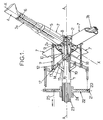
- the quadruple rear rotor for helicopter of the Figure 1 includes a shaft or rotor mast 1 driven by its base (not shown on the left of the drawing) in rotation around the axis A-A of the rotor, and integral in rotation, at its opposite end, of a hub 2.
- This hub 2 comprises two hub plates such as 2a, stacked and bolted towards each other by enclosing the parts between them centrals which intersect with two twisted composite blades and flexible 3a and 3b, each constituting, on the one hand and other of its central part embedded in the hub 2, the spar of one of the four blades 4 opposite two by two, by its part and its outer radial end relative to to axis A-A, as well as the root portion 5 of this same blade 4, by the blade part 3a extending between the foot 6 of the blade 4 and the hub 2, crossing a cuff 7 rigid in torsion, metallic or made of material composite.
- each blade 4 is connected to hub 2 by the root portion 5 consisting of the twisting arm around the longitudinal axis X-X blade pitch change 4 and formed by the part of blade 3a (or 3b) extending between the blade root 6 and the hub 2.
- the sleeve 7 is integral with torsion, around the pitch axis X-X, of the blade root 6, of the blade 4 as well as the twisting arm 5 which it surrounds. Through against, the internal radial part of the cuff 7 surrounds without contact the part of the twisting arm 5 which is close to the hub 2.
- each blade 6 in beating is effected by bending of the torsible arm 5 and flexible around a fictitious beating axis extending substantially in the plane of rotation of the blades 4 and perpendicular to the pitch axis X-X of the blade 4 considered, in the part of the arm 5 adjacent to the hub 2;
- the oscillations each blade 4 is drawn by bending of the corresponding arm 5 around a drag axis which is parallel to the axis A-A of the rotor and cuts the axis X-X by pitch the blade 4 considered in the part of the arm 5 adjacent to the hub 2;
- the movements of each blade 4 in steps are allowed by twisting arm 5 around the pitch axis X-X, the blade pitch change 4 being controlled, according to lessons from US-A-4,297,080, thanks to two step levers 8 and 9, fixed on the side of the trailing edge and the leading edge of the blade 4 on the end part internal radial of
- the step levers 8 and 9 extend projecting to the rear of the trailing edge and to the front of the leading edge of the cuff 7, relative to the direction of rotation of the rotor, on the internal radial end of cuff 7, so that the two step levers 8 and 9 extend in the extension of one another, in opposite directions on directly opposite parts of the sleeve 7 with respect to the X-X axis.
- Each of the two levers of pitch 8 and 9 is articulated on a ball end of a end of one respectively of two rods identical intermediates 10 and 11, extending substantially parallel to the axis of the rotor A-A.
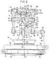
- Figure 2 partially shows a first example of a helicopter quadruple main rotor for which, for the sake of simplification and clarity, we content to represent the root portion of a single pale, the corresponding cuff limited to its part tubular internal radial end which supports the step levers, and control device components steps needed to control this single blade as well than a corresponding drag damper.
- This rotor comprises a rotor mast 31 driven in rotation by its base around the axis A-A of the rotor, and of which the upper end is integral in rotation with a hub 32 with two plates 32a arranged one above the other and presenting each and for each blade one of two arms radials 32b, arranged one above the other, and forming a mounting cap on the hub 32 of the end internal radial (relative to the rotor axis A-A) of an arm twistable and flexible 35 constituting the root portion of a blade (not shown).
- each of the two arm 32b of a yoke is pierced in a known manner by two facing bores with the two corresponding bores of the other arm for the passage of through fixing pins corresponding bores in the radial part internal of arm 35 so as to retain it embedded between the two plates 32a of the hub 32 by its internal radial part.
- the arm 35 is surrounded by a torsionally rigid cuff 37, torsionally secured, by its outer radial end, from the foot of the blade (not shown) as well as the outer radial end of the arm twistable 35 by known means (not shown) capable of include a clevis with two elements bolted to one the other by enclosing between them the radial ends of the arm 35 and the cuff 37, and between which the foot of the blade is retained, in a well known manner, for example by two pins, one of which is possibly removable to allow "folding" of the blade by pivot around the other spindle in this yoke retained at its root portion (arm 35) on the hub 32.
- known means capable of include a clevis with two elements bolted to one the other by enclosing between them the radial ends of the arm 35 and the cuff 37, and between which the foot of the blade is retained, in a well known manner, for example by two pins, one of which is possibly removable to allow
- the cuff 37 which surrounds the twisting arm 35 without contact, carries two step levers 38 and 39 projecting one from the edge side leading and the other on the trailing edge of the blade corresponding.
- the two step levers 38 and 39 are identical, symmetrical about the longitudinal X-X axis of the arm torsible 35, which is also the pitch change axis of the corresponding blade, and each of the two step levers 38 and 39 is shaped like a screed with two parallel branches which are symmetrical to each other with respect to a parallel plane to the rotor axis A-A and perpendicular to the pitch axis X-X of the blade, and containing the virtual or fictitious axes of beat and drag of this blade, and around which the arm 35 deforms in bending.
- each step lever 38 or 39 is retained a ball joint 40a or 41a mounted in the upper end, arranged in ball end, of one of two links respectively identical intermediates 40 and 41 with longitudinal axes parallel to the axis A-A of the rotor.
- the lower end of each of the links 40 and 41 is arranged in a yoke 40b or 41b with two branches parallel to each other and substantially to the branches of the yoke levers of steps 38 and 39, and in each of the yokes 40b and 41b is retained a ball joint articulation 46 or 47 mounted in a return lever 42.
- This return lever 42 has, between the ball joint 46 and the ball joint 47, which is close to one end of the lever reference 42, a third hinge ball joint 43 retained in a yoke 44 for pivoting the lever 42, this yoke 44 being fixed cantilevered to the rotor mast 31 by a side console 45 which is secured at one end of the yoke 44 and by the other end of the rotor mast 31.
- the articulation ball joints 46 and 47 are mounted symmetrically to each other with respect to the ball joint 43 of the pivoting link of the reference 42 on the yoke 44 integral in rotation with the rotor mast 31.
- the reference 42 is equipped with a fourth ball joint hinge 48 retained in a yoke 49b at the end top of a main or pitch control rod 49 of the corresponding blade, individually connected to the hub 32 by the corresponding twisting arm 35.
- the end lower of the pitch control rod 49 is fitted with ball joint (not shown) articulated in a yoke 50 with two radial branches projecting outwards on the turntable 52 of a swashplate device 51, of well known structure, also comprising a non-turntable 53, on which the turntable 52 is mounted coaxially in rotation by at least one bearing ball.
- the two plates 52 and 53 are guided in translation parallel to the axis A-A by two balusters 54, with an axis parallel to the rotor axis A-A, and along which slides the slide 55 to which the plate non-rotating 53 is connected in a known manner by a ball joint not visible in Figure 2 and guiding the inclinations of the plates 52 and 53 around the rotor axis A-A.
- the non-rotating plate 53 also has three yokes such as 57 projecting radially outwards, and by each of which it is articulated at the end top of one of three servo actuators respectively (not shown) articulated by their ends lower on a non-rotating part of the structure the helicopter.
- the control of the general step is ensured by actuating, using the servo actuator cylinders, the two plates 52 and 53 in translation along the axis A-A, while the control of the cyclic step is ensured in controlling their inclination on this axis A-A.
- the pitch control rod 49 pushes or traction on the end of the return lever 42 fitted of the ball joint 48.
- the return lever 42 pivots thus around the retaining axis of its ball joint 43 in the clevis 44, which causes a push in one of the two rods 40 and 41 and a pull in the other.
- step levers 38 and 39 are thus pressed one towards the up and the other down, so a pure couple is introduced into cuff 37, which transmits this torque to the blade controlled in pitch by deforming the arm 35 in torsion around the X-X axis.
- the operation of the pitch control rod 49 or 19, substantially in the direction of axis A-A of the rotor, by the actuation mechanism consisting of the swashplate device 51 or the control plate device 22 of the previous example, is transformed, by the articulation of this connecting rod 49 or 19 on the return lever 42 or 12 at a point offset from the pivoting link 43 or 13 of the latter on a fixed point (44, 14) relative to the rotor mast 1 or 31, in two stresses antagonists of the intermediate links 40 and 41 or 10 and 11, causing the two step levers 38 and 39 or 8 and 9 rotating in the same direction around the pitch axis X-X of the corresponding blade.
- the two levers of steps 8 and 9 or 38 and 39 are the same length, as well as the two intermediate links 10 and 11 or 40 and 41, and are essentially straight elements. Both rods 10 and 11 or 40 and 41 are requested by the return lever 12 or 42 with equal lever arms by relative to the pivoting link 13 or 43 of the return lever 12 or 42 on the pivot 14 or 44 rigidly connected to the rotor mast 1 or 31. These lever arms are each greater than the half of the lever arm with which the control rod of step 19 or 49 requests the return lever 12 or 42, for relative to the pivot connection 13 or 43 of the latter on the pivot 14 or 44.
- joints such as 40a and 41a of the two step levers 38 and 39 or 8 and 9 on the links intermediaries 40 and 41 or 10 and 11 are centered on the beating axis, so as to obtain a good locking in flap of cuff 37 or 7, while ensuring blade pitch control without step-beat coupling.
- these joints are centered, at rest, in the plane parallel to the axis of the rotor A-A and perpendicular to the pitch axis X-X of the blade which contains the axis fictitious drag, so as to reduce the not-drag couplings.
- this pitch control device is neutral vis-à-vis the displacements parallel to the X-X axis of the pale, under the effect of centrifugal force.
- the geometry of the device means that the ball joints of the joints of the intermediate links 10 and 11 or 40 and 41 are subjected to a force less than those of the joints of the pitch rod 19 or 49, this which guarantees their resistance over time.
- these joints ball joints are easily inspectable and removable.
- the cost of direct mounting as well as the cost of maintenance of such a device are much lower than those of known devices with laminated support bearing.
- the return lever 42 in the form general straight and elongated, thinned in three zones located between its four articulation ball joints 43, 46, 47 and 48, which has the effect of lightening it, without disturb the alignment of the centers of the ball joints on the axis longitudinal of this return lever 42.
- the device of FIG. 2 comprises, in addition to the components of that of FIG. 1, and for each blade of the rotor, a cross member 58, extending between the two intermediate links 40 and 41, on each of which the crosspiece 58 is articulated, between the two ends of the corresponding rod 40 or 41, by one respectively of two end caps 59 and 60.
- the cross-member 58 is equipped, in its middle, a ball 63 of articulation in a end yoke 64 of a single shock absorber assembly streak shown schematically in 65, and articulated at its other end by a ball joint 66 on a fixed point 67 rigidly linked to the rotor mast 31, and therefore integral in rotation with this latest.
- the shock absorber 65 of drag of the corresponding blade linked to the twisting arm 35 is thus stressed by the drag deformations of the deformable double parallelogram constituted by the two links 40 and 41, the two levers of steps 38 and 39 and the cuff 37, the crosspiece 58 and the return lever 42 articulated in the pivot yoke 44 fixed in rotating reference.
- the center of the ball joint 43 of the return lever 42 on the pivot yoke 44 as well as the center of the ball 63 of articulation of the middle of the cross member 58 on one end of the shock absorber assembly line 65 are located in the same radial plane passing through the axis of the rotor A-A as well as by the axis of pitch X-X of the arm twist 35 and the corresponding blade, so that the step control, on the one hand, and amortization of the drag, on the other hand, can be insured simultaneously and independently of each other, without introduction of not-dragged coupling.
- the centers of the ball joints 61 and 62 of articulation of the cross member 58 on the rods 40 and 41 are, like the centers of the ball joints 40a and 41a of articulation of these same rods on the levers of steps 38 and 39, located in the plane parallel to the axis A-A and passing through the fictional beat axis, so that the train pitch control and damping device thus obtained is insensitive to the beating of the blade corresponding.
- the drag damper 65 has been diagrammed as a hydraulic shock absorber with cylinder 65a filled with hydraulic fluid and in which slides a piston 65b secured to a rod 65c, with rolling of the fluid hydraulic between piston 65b and cylinder 65a and / or by orifices in the piston 65b, the rod 65c carrying the yoke 64 at its end external to the cylinder 65a to be articulated to the cross member 58, while the cylinder 65a is connected to the opposite end of the shock absorber 65, at the joint 66 on the fixed point 67 in rotating reference.
- the shock absorber 65 is hydro-elastic or hydro-visco-elastic, and / or connected by its rod 65c to the joint 66 and by its cylinder 65a to the yoke 64 of articulation in 63 on the crosspiece 58, or that the shock absorber 65 is visco-elastic, with at least one layer of viscoelastic material subjected to shear between two rigid plates, one of which is connected to articulation 66 and the other, at clevis 64.
- the shock absorber 65 can have any suitable and known structure drag damper.
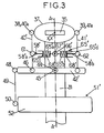
- FIG. 3 schematically represents a variant of the rotor of FIG. 2, on which the identical elements or similar to those of FIG. 2 are identified by identical or symbol-assigned numeric references premium.
- the damper of 65 'drag of the shock absorber assembly is double, two symmetrical stages of each other and on both sides from a midpoint 66 ', which corresponds to the middle of the crosspiece 58 'in which the shock absorber 65' is integrated.
- This midpoint 66 ' is arranged in a hinge central, by which the shock absorber 65 'is articulated around a fixed point 67 ', integral in rotation with the rotor mast 31 because rigidly linked to the latter by a lateral arm of stem (not visible in Figure 3 in side elevation), such that the center of the central articulation 66 'is not only in the radial plane passing through the axes A-A and X-X and through the center of the articulation 43 of the lever 42 'on its pivot 44 but also located on an axis parallel to the rotor axis A-A and passing through the center of the joint 43 of the return lever 42 'on the center of the pivot 44 linked to the rotor mast 31.
- the shock absorber 65 'integrated into the crosspiece 58' is installed parallel to the return lever 42 ', and its ends are linked to intermediate links 40 'and 41 'by the ends of the crosspiece 58' which are articulated on these rods 40 'and 41' by the joints 61 and 62.
- the damper 65 ' can be of the damping fluid type and include, as schematically represented on Figure 3, two cylinders 65'a and 65'b integral with the central articulation 66 ′ on either side of this last, and in each of which one slides respectively two pistons 65'c and 65'd linked to rods shock absorbers 58'a and 58'b formed by the parts opposite ends of the crosspiece 58 '.
- each stage of the double shock absorber 65 ' like that of 65 Figure 2, or of another type, for example at least a layer of viscoelastic material sheared between two rigid supports linked to opposite ends of the floor shock absorber.
- each shock absorber 65 or 65 ' is in fact associated with elastic return means, such as one or more several springs 68 or 68 ', for example each mounted between a cylinder and a damper piston, so known, to constitute a frequency adapter having a determined stiffness and thus mounted between the cuff 37 and the hub, via the rods 40 and 41 or 40 ' and 41 ′ and of the rotor mast 31 to give the corresponding blade, in known manner, a natural frequency in drag favorable towards ground-resonance and / or kinematic chain resonance.
- This drag adapter is thus only solicited by drag movements of the corresponding blade and cuff 37, and remains insensitive to the step and beat movements of this blade.
- the devices of Figures 2 and 3 have the advantage to be reliable and long-lasting, because their components are lightly loaded, while ensuring introduction pure control torques in the headlines torsionally rigid, for the transmission of pitch to the blades, and ensuring a cushioning and a good adaptation dynamic in drag without coupling with the pitch and beats.
Landscapes
- Engineering & Computer Science (AREA)
- Mechanical Engineering (AREA)
- Aviation & Aerospace Engineering (AREA)
- Transmission Devices (AREA)
Description
- un mât rotor est entraíné en rotation autour d'un axe du rotor,
- un moyeu est solidaire en rotation du mât,
- au moins deux pales sont chacune, d'une part, reliée au moyeu par une partie d'emplanture comprenant au moins un bras torsible autour d'un axe longitudinal de changement de pas de la pale, et, d'autre part, munie d'une manchette rigide en torsion, entourant le bras torsible, et dont la partie radiale externe, par rapport à l'axe du rotor, est solidaire en torsion de la pale et du bras torsible autour de l'axe de pas, tandis que sa partie radiale interne entoure sans contact le bras torsible et présente deux leviers de pas fixés l'un sur le bord d'attaque et l'autre sur le bord de fuite de la manchette, chaque levier de pas étant articulé à une extrémité de l'une respectivement de deux biellettes intermédiaires dont les autres extrémités sont articulées à un levier de renvoi, de part et d'autre d'une liaison pivotante du levier de renvoi sur un pivot solidaire en rotation du mât rotor, le levier de renvoi étant relié par une articulation décalée par rapport à sa liaison pivotante, à une bielle de commande de pas correspondante manoeuvrée sensiblement dans la direction de l'axe A-A du rotor par un mécanisme d'actionnement relié aux commandes de vol actionnées par le pilote.
- la figure 1 est une vue schématique en partie en perspective et en partie en coupe d'un dispositif de commande de pas connu par US-A-4,297,080 et équipant un rotor arrière,
- la figure 2 est une vue en élévation latérale d'un rotor principal d'hélicoptère équipé du dispositif de commande de pas selon l'invention limité, dans un but de simplicité, aux composants nécessaires pour une seule pale du rotor, et
- la figure 3 est une vue schématique en élévation latérale d'une variante de rotor selon la figure 2, dont l'amortisseur de traínée est double.
Claims (9)
- Dispositif de commande de pas pour rotor du type dit "sans articulation", et dans lequel :un mât rotor (31) est entraíné en rotation autour d'un axe du rotor (A-A),un moyeu (32) est solidaire en rotation du mât (31),au moins deux pales sont chacune, d'une part, reliée au moyeu (32) par une partie d'emplanture comprenant au moins un bras (35) torsible autour d'un axe (X-X) longitudinal de changement de pas de la pale, et, d'autre part, munie d'une manchette (37) rigide en torsion, entourant le bras torsible (35), et dont la partie radiale externe, par rapport à l'axe (A-A) du rotor, est solidaire en torsion de la pale et du bras torsible (35) autour de l'axe de pas (X-X), tandis que sa partie radiale interne entoure sans contact le bras torsible (35) et présente deux leviers de pas (38, 39) fixés l'un sur le bord d'attaque et l'autre sur le bord de fuite de la manchette (37), chaque levier de pas (38-39) étant articulé à une extrémité de l'une respectivement de deux biellettes intermédiaires (40', 41') dont les autres extrémités sont articulées à un levier de renvoi (42, 42'), de part et d'autre d'une liaison pivotante (43) du levier de renvoi (42') sur un pivot (44) solidaire en rotation du mât rotor (31), le levier de renvoi (42') étant relié par une articulation (48) décalée par rapport à sa liaison pivotante (43), à une bielle de commande de pas (49) correspondante manoeuvrée sensiblement dans la direction de l'axe (A-A) du rotor par un mécanisme d'actionnement (51') relié aux commandes de vol actionnées par le pilote,
caractérisé en ce que, pour chaque pale, une traverse (58, 58') est disposée entre les deux biellettes intermédiaires (40', 41') et articulée (61, 62) sur chacune desdites biellettes entre les extrémités de chaque biellette, et ladite traverse (58, 58') coopère avec un ensemble comportant au moins un amortisseur (65, 65') de traínée de la pale correspondante, ledit ensemble étant articulé sur un point fixe (67, 67') solidaire en rotation du mât rotor (31). - Dispositif de commande de pas selon la revendication 1, caractérisé en ce que, pour chaque pale, la traverse (58) est articulée (63) par son milieu sur ledit ensemble avec amortisseur (65) de traínée, lequel ensemble est articulé (66) par ailleurs sur ledit point fixe (67), solidaire en rotation du mât rotor (31).
- Dispositif de commande de pas selon la revendication 2, caractérisé en ce que, pour chaque pale, les centres de la liaison pivotante (43) du levier de renvoi (42) sur son pivot (44) et de l'articulation (63) de la traverse (58) sur l'ensemble à amortisseur de traínée (65) sont sensiblement dans un même plan radial, par rapport à l'axe (A-A) du rotor, passant par l'axe de pas (X-X) de la pale correspondante.
- Dispositif de commande de pas selon la revendication 1, caractérisé en ce que, pour chaque pale, ledit ensemble avec amortisseur de traínée (65') est intégré à la traverse (58'), l'amortisseur (65') étant double, à deux étages symétriques par rapport à un point milieu, correspondant au milieu de la traverse (58'), et aménagé en articulation centrale (66') par laquelle ledit ensemble est articulé sur ledit point fixe (67') solidaire en rotation du mât rotor (31).
- Dispositif de commande de pas selon la revendication 4, caractérisé en ce que, pour chaque pale, les centres de la liaison pivotante (43) du levier de renvoi (42') sur son pivot (44) et de ladite articulation centrale (66') de l'ensemble à amortisseur double (65') sur ledit point fixe (67') lié au mât rotor (31) sont sensiblement dans un même plan radial, par rapport à l'axe (A-A) du rotor, passant par l'axe de pas (X-X) de la pale correspondante.
- Dispositif de commande de pas selon la revendication 5, caractérisé en ce que, pour chaque pale, ladite articulation centrale (66') est située sur un axe parallèle à l'axe rotor (A-A) et passant par le centre de la liaison pivotante (43) du levier de renvoi (42') sur son pivot (44).
- Dispositif de commande de pas selon l'une des revendications 1 à 6, caractérisé en ce que l'amortisseur de traínée (65, 65') est associé à des moyens élastiques de rappel dans ledit ensemble constituant un adaptateur de fréquence, monté entre la manchette (37) correspondante et le moyeu (32) par l'intermédiaire des biellettes intermédiaires (40, 41, 40', 41') et du mât rotor (31).
- Dispositif de commande de pas selon l'une des revendications 1 à 7, caractérisé en ce que les distances séparant les centres des articulations (40a-61, 41a-62) de chaque biellette intermédiaire (40, 41, 40', 41') sur le levier de pas (38, 39) correspondant et sur la traverse (58, 58') sont égales.
- Dispositif de commande de pas selon l'une quelconque des revendications 1 à 8, caractérisé en ce que, pour chaque pale, le pivot (44) est relié rigidement au mât rotor (31) par au moins une potence latérale (45), la bielle de commande de pas (49) est articulée (48) sur une extrémité du levier de renvoi (42, 42') sensiblement rectiligne, et les deux leviers de pas (38, 39) sont en saillie l'un vers l'avant et l'autre vers l'arrière de ladite manchette (37) correspondante, et sensiblement de même longueur, ainsi que les deux biellettes intermédiaires (40-41, 40'-41'), sensiblement rectilignes.
Applications Claiming Priority (2)
| Application Number | Priority Date | Filing Date | Title |
|---|---|---|---|
| FR9412115 | 1994-10-11 | ||
| FR9412115A FR2725420B1 (fr) | 1994-10-11 | 1994-10-11 | Dispositif de commande de pas pour rotor sans articulation |
Publications (2)
| Publication Number | Publication Date |
|---|---|
| EP0706936A1 EP0706936A1 (fr) | 1996-04-17 |
| EP0706936B1 true EP0706936B1 (fr) | 1999-01-07 |
Family
ID=9467748
Family Applications (1)
| Application Number | Title | Priority Date | Filing Date |
|---|---|---|---|
| EP95402239A Expired - Lifetime EP0706936B1 (fr) | 1994-10-11 | 1995-10-06 | Perfectionnements aux dispositifs de commande de pas pour rotors sans articulation |
Country Status (4)
| Country | Link |
|---|---|
| US (1) | US5562415A (fr) |
| EP (1) | EP0706936B1 (fr) |
| DE (1) | DE69507103T2 (fr) |
| FR (1) | FR2725420B1 (fr) |
Families Citing this family (8)
| Publication number | Priority date | Publication date | Assignee | Title |
|---|---|---|---|---|
| FR2761660B1 (fr) * | 1997-04-08 | 1999-06-11 | Onera (Off Nat Aerospatiale) | Dispositif de commande individuelle des pales de rotor de voilures tournantes d'aeronefs avec plateaux cycliques multiples |
| US6394387B1 (en) * | 2000-12-22 | 2002-05-28 | Pratt & Whitney Canada Corp. | Rotor shaft support and drive arrangement |
| US8142158B2 (en) | 2005-12-02 | 2012-03-27 | Sikorsky Aircraft Corporation | Compact load path swashplate assembly |
| EP2274203A4 (fr) * | 2008-04-23 | 2014-10-15 | Abe Karem | Systèmes de moyeu de rotor et procédés associés |
| US9457889B2 (en) * | 2013-09-24 | 2016-10-04 | The Boeing Company | Rotorcraft rotor including primary pitch horns and secondary horns |
| US11014658B1 (en) | 2015-01-02 | 2021-05-25 | Delbert Tesar | Driveline architecture for rotorcraft featuring active response actuators |
| US20170341733A1 (en) * | 2016-05-27 | 2017-11-30 | Sikorsky Aircraft Corporation | Rotor head for prop-rotor |
| US10994840B1 (en) | 2017-08-16 | 2021-05-04 | United States Of America As Represented By The Secretary Of The Air Force | Thrust vectoring control of a cyclorotor |
Family Cites Families (15)
| Publication number | Priority date | Publication date | Assignee | Title |
|---|---|---|---|---|
| US2939535A (en) * | 1954-09-13 | 1960-06-07 | Ryan Aeronautical Co | Rotor for self-stabilizing helicopter |
| FR1593008A (fr) * | 1968-07-11 | 1970-05-25 | ||
| FR2119828B1 (fr) * | 1970-12-14 | 1974-02-15 | Aerospatiale | |
| FR2285298A1 (fr) * | 1974-09-19 | 1976-04-16 | Aerospatiale | Agencement de rotor de queue pour giravions |
| US4073600A (en) * | 1976-06-14 | 1978-02-14 | William Gallagher | Damping mechanism for the rotor hub of a helicopter for ground resonance and waddle and its combination with the rotor |
| US4297080A (en) * | 1979-12-17 | 1981-10-27 | United Technologies Corporation | Rotor blade pitch control linkage |
| DE3036093C1 (de) * | 1980-09-25 | 1982-07-29 | Messerschmitt-Bölkow-Blohm GmbH, 8000 München | Rotor insbesondere fuer ein Drehfluegelflugzeug |
| DE3265934D1 (en) * | 1982-02-02 | 1985-10-10 | Messerschmitt Boelkow Blohm | Rotor, particularly for a rotary wing aircraft |
| FR2542695B1 (fr) * | 1983-03-18 | 1985-07-26 | Aerospatiale | Helice multipale a pas variable a pale s en materiaux composites demontables individuellement, procede de fabrication de telles pales et pales ainsi realisees |
| DE3401737A1 (de) * | 1984-01-19 | 1985-07-25 | Messerschmitt-Bölkow-Blohm GmbH, 8012 Ottobrunn | Rotor, insbesondere eines drehfluegelflugzeuges |
| DE3526470C1 (de) * | 1985-07-24 | 1987-01-02 | Messerschmitt Boelkow Blohm | Rotor,insbesondere eines Drehfluegelflugzeugs |
| US4778340A (en) * | 1985-11-25 | 1988-10-18 | Costruzioni Aeronautiche Giovanni Augusta S.P.A. | Main helicopter rotor |
| DE3603400C1 (en) | 1986-02-05 | 1987-05-14 | Messerschmitt Boelkow Blohm | Control device for rotor blade adjustment, especially in the case of a rotary-wing aircraft |
| GB8922338D0 (en) * | 1989-10-04 | 1989-11-22 | Westland Helicopters | Helicopter rotors |
| DE69228246T2 (de) * | 1991-08-02 | 1999-08-19 | Boeing Co | Mantelgebläse und blattverstellsteuerung eines drehflügelflugzeugheckrotors |
-
1994
- 1994-10-11 FR FR9412115A patent/FR2725420B1/fr not_active Expired - Fee Related
-
1995
- 1995-10-05 US US08/539,651 patent/US5562415A/en not_active Expired - Lifetime
- 1995-10-06 DE DE69507103T patent/DE69507103T2/de not_active Expired - Fee Related
- 1995-10-06 EP EP95402239A patent/EP0706936B1/fr not_active Expired - Lifetime
Also Published As
| Publication number | Publication date |
|---|---|
| EP0706936A1 (fr) | 1996-04-17 |
| DE69507103D1 (de) | 1999-02-18 |
| US5562415A (en) | 1996-10-08 |
| FR2725420B1 (fr) | 1996-12-13 |
| FR2725420A1 (fr) | 1996-04-12 |
| DE69507103T2 (de) | 1999-08-19 |
Similar Documents
| Publication | Publication Date | Title |
|---|---|---|
| EP0680876B1 (fr) | Rotor anti-couple caréné à pales flottantes | |
| EP0080920B1 (fr) | Rotor pour giravions, à articulations intégrées dans le pied de pale | |
| EP0021901B1 (fr) | Rotor de giravion à moyeu articulé compact | |
| EP0424267B1 (fr) | Dispositif visco-élastique rotatif de rappel élastique et d'amortissement en traînée pour pale de rotor de giravion, et tête de rotor le comportant | |
| EP1348623A1 (fr) | Rotor de giravion à entraínement homocinétique avec différentiel de partage de couple | |
| EP0213016B1 (fr) | Mât-moyeu intégré et tête de rotor de giravion le comportant | |
| FR2928621A1 (fr) | Commande de vol d'un aeronef. | |
| EP0340095A1 (fr) | Tête de rotor de giravion à tirants interpales de rappel élastique avec amortissement incorporé | |
| FR2946316A1 (fr) | Procede de controle en lacet d'un helicoptere hybride,et helicoptere hybride muni d'un dispositif de commande en lacet apte a mettre en oeuvre ledit procede | |
| EP1346910A1 (fr) | Rotor de giravion a entraínement homocinétique | |
| EP0545750B1 (fr) | Rotor multipale à pas variable, notamment pour système arrière anticouple d'aéronef à voilure tournante | |
| FR2943621A1 (fr) | Pale munie d'un amortisseur de trainee et rotor muni d'une telle pale | |
| EP0742144B1 (fr) | Rotor avec dispositif d'amortissement de trainée des pales | |
| EP0457646B1 (fr) | Dispositif à plateaux cycliques montés sur articulations découplées en tangage et roulis, pour la commande du pas des pales d'un rotor de giravion | |
| EP0706936B1 (fr) | Perfectionnements aux dispositifs de commande de pas pour rotors sans articulation | |
| EP0706937B1 (fr) | Dispositif de commande du pas des pales d'un rotor de giravion | |
| EP0718187B1 (fr) | Dispositif de suspension anti-vibratoire bidirectionnelle pour rotor d'hélicoptère | |
| FR2728538A1 (fr) | Dispositif de suspension anti-vibratoire de rotor d'helicoptere | |
| EP0521792B1 (fr) | Tête de rotor de giravion, rigide en traînée et articulée en pas et battement | |
| WO1998056656A1 (fr) | Rotor de giravion a moyeu bi-plateau et commande de pas partiellement externe | |
| EP0718188B1 (fr) | Rotor sans articulation à anneaux intermédiaires de commande de pas | |
| EP0402236B1 (fr) | Dispositif de butées escamotables pour pales de rotors de giravions, et tête de rotor le comportant | |
| EP0211740B1 (fr) | Mât-moyeu intégré et téte de rotor de giravion le comportant | |
| EP0215688B1 (fr) | Dispositif de butées de battement pour rotor de giravion | |
| FR2830237A1 (fr) | Aerodyne a decollage et atterissage verticaux comprenant des nacelles d'helice aptes a pivoter librement de 90° sous le controle de moyens de freinage |
Legal Events
| Date | Code | Title | Description |
|---|---|---|---|
| PUAI | Public reference made under article 153(3) epc to a published international application that has entered the european phase |
Free format text: ORIGINAL CODE: 0009012 |
|
| AK | Designated contracting states |
Kind code of ref document: A1 Designated state(s): DE GB IT |
|
| 17P | Request for examination filed |
Effective date: 19960812 |
|
| RAP1 | Party data changed (applicant data changed or rights of an application transferred) |
Owner name: EUROCOPTER |
|
| GRAG | Despatch of communication of intention to grant |
Free format text: ORIGINAL CODE: EPIDOS AGRA |
|
| 17Q | First examination report despatched |
Effective date: 19980428 |
|
| GRAG | Despatch of communication of intention to grant |
Free format text: ORIGINAL CODE: EPIDOS AGRA |
|
| GRAH | Despatch of communication of intention to grant a patent |
Free format text: ORIGINAL CODE: EPIDOS IGRA |
|
| GRAH | Despatch of communication of intention to grant a patent |
Free format text: ORIGINAL CODE: EPIDOS IGRA |
|
| GRAA | (expected) grant |
Free format text: ORIGINAL CODE: 0009210 |
|
| AK | Designated contracting states |
Kind code of ref document: B1 Designated state(s): DE GB IT |
|
| REF | Corresponds to: |
Ref document number: 69507103 Country of ref document: DE Date of ref document: 19990218 |
|
| GBT | Gb: translation of ep patent filed (gb section 77(6)(a)/1977) |
Effective date: 19990212 |
|
| ITF | It: translation for a ep patent filed |
Owner name: BARZANO' E ZANARDO MILANO S.P.A. |
|
| PLBE | No opposition filed within time limit |
Free format text: ORIGINAL CODE: 0009261 |
|
| STAA | Information on the status of an ep patent application or granted ep patent |
Free format text: STATUS: NO OPPOSITION FILED WITHIN TIME LIMIT |
|
| 26N | No opposition filed | ||
| REG | Reference to a national code |
Ref country code: GB Ref legal event code: IF02 |
|
| PGFP | Annual fee paid to national office [announced via postgrant information from national office to epo] |
Ref country code: DE Payment date: 20040924 Year of fee payment: 10 |
|
| PG25 | Lapsed in a contracting state [announced via postgrant information from national office to epo] |
Ref country code: DE Free format text: LAPSE BECAUSE OF NON-PAYMENT OF DUE FEES Effective date: 20060503 |
|
| PGFP | Annual fee paid to national office [announced via postgrant information from national office to epo] |
Ref country code: GB Payment date: 20090928 Year of fee payment: 15 |
|
| PGFP | Annual fee paid to national office [announced via postgrant information from national office to epo] |
Ref country code: IT Payment date: 20091009 Year of fee payment: 15 |
|
| GBPC | Gb: european patent ceased through non-payment of renewal fee |
Effective date: 20101006 |
|
| PG25 | Lapsed in a contracting state [announced via postgrant information from national office to epo] |
Ref country code: GB Free format text: LAPSE BECAUSE OF NON-PAYMENT OF DUE FEES Effective date: 20101006 |
|
| PG25 | Lapsed in a contracting state [announced via postgrant information from national office to epo] |
Ref country code: IT Free format text: LAPSE BECAUSE OF NON-PAYMENT OF DUE FEES Effective date: 20101006 |