EP0706033A2 - Vorrichtung zur Sicherheit und Flüssigkeitsniveauanzeige für einen Dampfheizungskessel - Google Patents
Vorrichtung zur Sicherheit und Flüssigkeitsniveauanzeige für einen Dampfheizungskessel Download PDFInfo
- Publication number
- EP0706033A2 EP0706033A2 EP95115635A EP95115635A EP0706033A2 EP 0706033 A2 EP0706033 A2 EP 0706033A2 EP 95115635 A EP95115635 A EP 95115635A EP 95115635 A EP95115635 A EP 95115635A EP 0706033 A2 EP0706033 A2 EP 0706033A2
- Authority
- EP
- European Patent Office
- Prior art keywords
- heating tank
- level
- heating
- liquid
- signalling
- Prior art date
- Legal status (The legal status is an assumption and is not a legal conclusion. Google has not performed a legal analysis and makes no representation as to the accuracy of the status listed.)
- Withdrawn
Links
- 238000010438 heat treatment Methods 0.000 title claims abstract description 89
- 239000007788 liquid Substances 0.000 title claims abstract description 31
- 230000011664 signaling Effects 0.000 claims abstract description 39
- 230000000007 visual effect Effects 0.000 claims abstract description 18
- 239000000523 sample Substances 0.000 claims description 10
- 239000003086 colorant Substances 0.000 claims description 6
- XLYOFNOQVPJJNP-UHFFFAOYSA-N water Substances O XLYOFNOQVPJJNP-UHFFFAOYSA-N 0.000 description 16
- 239000011810 insulating material Substances 0.000 description 2
- 235000000396 iron Nutrition 0.000 description 2
- 230000002860 competitive effect Effects 0.000 description 1
- 230000006866 deterioration Effects 0.000 description 1
- 238000010586 diagram Methods 0.000 description 1
- 230000000670 limiting effect Effects 0.000 description 1
- 238000004519 manufacturing process Methods 0.000 description 1
- 239000000463 material Substances 0.000 description 1
- 230000004048 modification Effects 0.000 description 1
- 238000012986 modification Methods 0.000 description 1
Images

Classifications
-
- G—PHYSICS
- G01—MEASURING; TESTING
- G01F—MEASURING VOLUME, VOLUME FLOW, MASS FLOW OR LIQUID LEVEL; METERING BY VOLUME
- G01F23/00—Indicating or measuring liquid level or level of fluent solid material, e.g. indicating in terms of volume or indicating by means of an alarm
- G01F23/22—Indicating or measuring liquid level or level of fluent solid material, e.g. indicating in terms of volume or indicating by means of an alarm by measuring physical variables, other than linear dimensions, pressure or weight, dependent on the level to be measured, e.g. by difference of heat transfer of steam or water
- G01F23/24—Indicating or measuring liquid level or level of fluent solid material, e.g. indicating in terms of volume or indicating by means of an alarm by measuring physical variables, other than linear dimensions, pressure or weight, dependent on the level to be measured, e.g. by difference of heat transfer of steam or water by measuring variations of resistance of resistors due to contact with conductor fluid
- G01F23/241—Indicating or measuring liquid level or level of fluent solid material, e.g. indicating in terms of volume or indicating by means of an alarm by measuring physical variables, other than linear dimensions, pressure or weight, dependent on the level to be measured, e.g. by difference of heat transfer of steam or water by measuring variations of resistance of resistors due to contact with conductor fluid for discrete levels
- G01F23/243—Schematic arrangements of probes combined with measuring circuits
-
- G—PHYSICS
- G01—MEASURING; TESTING
- G01F—MEASURING VOLUME, VOLUME FLOW, MASS FLOW OR LIQUID LEVEL; METERING BY VOLUME
- G01F23/00—Indicating or measuring liquid level or level of fluent solid material, e.g. indicating in terms of volume or indicating by means of an alarm
- G01F23/0007—Indicating or measuring liquid level or level of fluent solid material, e.g. indicating in terms of volume or indicating by means of an alarm for discrete indicating and measuring
- G01F23/0015—Indicating or measuring liquid level or level of fluent solid material, e.g. indicating in terms of volume or indicating by means of an alarm for discrete indicating and measuring with a whistle or other sonorous signal
-
- G—PHYSICS
- G01—MEASURING; TESTING
- G01F—MEASURING VOLUME, VOLUME FLOW, MASS FLOW OR LIQUID LEVEL; METERING BY VOLUME
- G01F23/00—Indicating or measuring liquid level or level of fluent solid material, e.g. indicating in terms of volume or indicating by means of an alarm
- G01F23/22—Indicating or measuring liquid level or level of fluent solid material, e.g. indicating in terms of volume or indicating by means of an alarm by measuring physical variables, other than linear dimensions, pressure or weight, dependent on the level to be measured, e.g. by difference of heat transfer of steam or water
- G01F23/24—Indicating or measuring liquid level or level of fluent solid material, e.g. indicating in terms of volume or indicating by means of an alarm by measuring physical variables, other than linear dimensions, pressure or weight, dependent on the level to be measured, e.g. by difference of heat transfer of steam or water by measuring variations of resistance of resistors due to contact with conductor fluid
- G01F23/241—Indicating or measuring liquid level or level of fluent solid material, e.g. indicating in terms of volume or indicating by means of an alarm by measuring physical variables, other than linear dimensions, pressure or weight, dependent on the level to be measured, e.g. by difference of heat transfer of steam or water by measuring variations of resistance of resistors due to contact with conductor fluid for discrete levels
- G01F23/243—Schematic arrangements of probes combined with measuring circuits
- G01F23/244—Schematic arrangements of probes combined with measuring circuits comprising oscillating circuits
Definitions
- the present invention relates to a safety and liquid-level indicating device for steam heating tanks and the like, particularly for irons.
- thermostat means adapted to control the temperature of the heating means. If the appliance is activated without water, the heating means increase their temperature, which is detected by the thermostat and switches on alarm means constituted for example by a warning light.
- the above mentioned solution does not allow to know, at least approximately, the level reached by the liquid inside the heating tank during use.
- Another drawback resides in the fact that the user, while filling the heating tank, does not know the level reached by the liquid inside said heating tank and thus risks introducing excess liquid.
- a principal aim of the present invention is therefore to solve the above mentioned problems by providing a safety and liquid level-indicating device for a steam heating tank, adapted to intervene when said level drops below a preset safety limit.
- an object of the present invention is to provide a device adapted to give the user a visual indication as regards the level of the liquid present in the heating tank.
- Another object of the present invention is to provide a device also capable of providing, in addition to a visual indication, an acoustic indication to warn the user that a particular condition is occurring.
- Another object of the present invention is to provide a device that is highly reliable, relatively easy to manufacture, and at competitive costs.
- a safety and liquid level-indicating device for steam heating tanks characterized in that it comprises: minimum-level sensing means, arranged inside the heating tank above heating means of said heating tank and being immersed in the liquid contained in said heating tank; maximum-level sensing means, also arranged inside said heating tank and being immersed in the liquid; said sensing means constituting an electric circuit adapted to be closed through the liquid contained in said heating tank; control and signalling means, inserted in said electric circuit through electrical lines connected to said sensing means and adapted to generate a signal that is sent to said sensing means and can be sensed by said control and signalling means, which are adapted to interrupt power supply to said heating means if there is insufficient or no liquid inside said heating tank; said control and signalling means comprising visual signalling means and acoustic signalling means, adapted to emit, respectively, light and sound indications at the beginning of, and during, operations for filling or emptying said heating tank in relation to particular levels reached by said liquid inside
- the reference numeral 1 designates the heating tank.
- Said heating tank 1 is internally provided with heating means 2 constituted by a conventional electrical resistor.
- the heating tank is adapted to be filled with water to produce steam.
- Means 3 for sensing the preset maximum level of the water contained in the heating tank are inserted in the heating tank 1 above the heating means 2.
- Said probe 3 which is folded downwardly inside the heating tank 1, protrudes from said heating tank with a straight portion inserted in a sheath 12 made of insulating material.
- Means 4 for sensing the preset minimum level of the water contained in the heating tank are inserted in the heating tank 1, also above the heating means 2.
- the probe 4 is folded downwardly too inside the heating tank 1 and protrudes from said heating tank with a straight portion inserted in a sheath 13 made of insulating material.
- the probes 3 and 4 are respectively connected, by means of electrical lines 6 and 7, to control and signalling means 8 constituted by an appropriate electronic board and adapted to interrupt the flow of electrical current to the heating means 2 of the heating tank 1 if there is insufficient or no water inside the heating tank and to indicate the level of the water that is present in said heating tank.
- the control and signalling means 8 are connected, at 9, to the mains power supply, and at 10 there is the relay that controls the disconnection of the power supply of the heating means 2 if there is no water inside the heating tank 1.
- the control and signalling means 8 drive visual signalling means 11 constituted by a light-emitting element (LED) having three primary colors: red, green, and blue.
- This light-emitting element is an electronic device that emits photons at different frequencies.
- the heating tank 1 is furthermore grounded at 5.
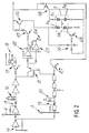
- control and signalling means 8 are described.
- the reference numeral 14 designates pulse generating means, advantageously constituted by an oscillator adapted to generate a square wave at the frequency of 100 Hz; the oscillator is connected to minimum-level sensing means 4 and to a first pulse sensing stage 15 adapted to sense the pulses originating from the pulse generating means 3.
- the signal reaches a delay (antibounce) circuit 16, which has the purpose of eliminating any bounces on the relay 18.
- the signal reaches the actuation means 17 of the relay 18, which are adapted to interrupt power supply to the heating means 2 inside the heating tank 1.
- the pulse generating means are also connected to the maximum-level sensing means 3, which are in turn connected to a second pulse sensing stage 19 adapted to sense the pulses originating from the pulse generating means 3.
- the signal passes from the second sensing stage 19 to a delay circuit 20 similar to the circuit 16.
- the signal passes through means for actuating the maximum-level acoustic signal 21, which drive acoustic signalling means constituted by a low-frequency oscillator 22 and by a high-frequency oscillator 23 that are mutually connected and respectively adapted to emit two modulated sounds at low and high frequencies.
- acoustic signalling device 24 constituted for example by an acoustic element of the piezoelectric type, is connected to the oscillator 23.
- the acoustic signalling means thus formed drives minimum-level actuation means 25, which are constituted by a transistor that is collector-connected to the base of a second transistor 26 and adapted to activate the red color of the visual signalling means 11.
- the output signal from the second delay circuit 20 furthermore enters the base of a transistor 27 that constitutes maximum-level actuation means, is collector-connected to the base of another transistor 28, and is adapted to activate the blue color of the visual signalling means 11.
- medium-level actuation means 29 constituted by a transistor, are base-connected to a medium-level antibounce delay circuit 30, adapted to produce a light-emission pause of the visual signalling means 11, and are collector-connected to said visual signalling means. Said medium-level actuation means are adapted to activate the green color of the visual signalling means 11.
- the visual signalling means 11 are constituted by a LED with three primary colors, in which, in figure 2, the reference numeral 11a designates the red light-emitting indicator, the reference numeral 11b designates the green one, and the reference numerals 11c and 11d designate the blue ones. There are two blue indicators to give this color greater brightness.
- the minimum-level probe 4 When the appliance is switched on, and assuming that no water is present in the heating tank 1, the minimum-level probe 4 is not immersed in the water and the circuit is open. In this case, the signal generated by the pulse generating means 14 reaches the sensing stage 15 and the relay 18 is de-energized, so as to interrupt power supply to the heating means 2. Simultaneously, the red light-emitting indicator 11a, actuated by the transistors 25 and 26, lights up intermittently. In addition to the visual signal, the device also activates the acoustic signalling means, producing a two-tone sound.
- the device assumes the state in which the probe 4, which is at this point immersed in the water, constitutes a closed circuit together with the wall of the heating tank 1. Therefore, the signal generated by the pulse generating means 14 does not reach the sensing stage 15 and the relay 18 is energized, so as to allow to supply electric power to the heating means 2.
- the device thus assumes the state in which the LED 11 becomes fixed green (light-emitting indicator 11b), indicating the medium level. At this point, no acoustic signalling is provided.
- the maximum-level probe 3 If water continues to be fed into the heating tank 1, the condition is reached in which the maximum-level probe 3 too constitutes a closed circuit together with the wall of the heating tank 1, so as to continuously activate the blue light-emitting indicators 11c and 11d that indicate the maximum level reached by the water inside the heating tank 1.
- a short tone frequency acoustic signal is also emitted at this level, thus sparing the user the need to constantly monitor the light-emitting indicator to avoid the water being introduced from overflowing out of the heating tank 1.
- the device passes from the final point to the intermediate point (green light-emitting indicator 11b lit continuously without acoustic signal) and then to the initial step (red indicator 11a lit intermittently with two-tone acoustic alarm).
- Said device in fact allows to check the level of the liquid inside a heating tank and to intervene, by interrupting the supply of electric power to the heating means, if said level is lower than a minimum level, which is preset by immersing the minimum-level probe inside the heating tank. Said preset minimum level in any case remains always adequately above the heating means. Furthermore, the possibility of using both a visual signal (in three colors) and an acoustic signal prevents the user from making any mistakes, allowing him to keep the level of the liquid fed into the heating tank constantly under control.
- the device according to the invention is susceptible of numerous modifications and variations, all of which are within the scope of the inventive concept. Furthermore, all the details may be replaced with technically equivalent elements. For example, instead of the single three-color light-emitting element (LED) 11 it is possible to provide three separate light-emitting elements capable of providing three different colors, each of which indicates a different level.
- LED three-color light-emitting element
Landscapes
- Physics & Mathematics (AREA)
- Fluid Mechanics (AREA)
- General Physics & Mathematics (AREA)
- Thermal Sciences (AREA)
- Cookers (AREA)
- Measurement Of Levels Of Liquids Or Fluent Solid Materials (AREA)
Applications Claiming Priority (2)
| Application Number | Priority Date | Filing Date | Title |
|---|---|---|---|
| ITBO940442A IT1274055B (it) | 1994-10-07 | 1994-10-07 | Dispositivo di indicazione del livello del liquido e di sicurezza per caldaie a vapore. |
| ITBO940442 | 1994-10-07 |
Publications (2)
| Publication Number | Publication Date |
|---|---|
| EP0706033A2 true EP0706033A2 (de) | 1996-04-10 |
| EP0706033A3 EP0706033A3 (de) | 1998-05-27 |
Family
ID=11340046
Family Applications (1)
| Application Number | Title | Priority Date | Filing Date |
|---|---|---|---|
| EP95115635A Withdrawn EP0706033A3 (de) | 1994-10-07 | 1995-10-04 | Vorrichtung zur Sicherheit und Flüssigkeitsniveauanzeige für einen Dampfheizungskessel |
Country Status (2)
| Country | Link |
|---|---|
| EP (1) | EP0706033A3 (de) |
| IT (1) | IT1274055B (de) |
Cited By (1)
| Publication number | Priority date | Publication date | Assignee | Title |
|---|---|---|---|---|
| SG102061A1 (en) * | 2002-01-30 | 2004-02-27 | Hong Bae Kim | Device for sensing and alarming absence of water in a home machine for manufacturing soyabean milk, watery bean curd, and bean curd |
Family Cites Families (8)
| Publication number | Priority date | Publication date | Assignee | Title |
|---|---|---|---|---|
| GB1583759A (en) * | 1976-10-07 | 1981-02-04 | Mettoy Co Ltd | Two-tone audible signal circuit |
| US4287407A (en) * | 1978-08-17 | 1981-09-01 | Hobart Corporation | Tank flushing delay arrangement for a steam generator |
| US4465088A (en) * | 1980-09-03 | 1984-08-14 | Vosper George W | Construction of low water level sensing device for hot water boiler |
| WO1984002401A1 (en) * | 1982-12-17 | 1984-06-21 | Kevyn Barry Moore | Water level monitor and/or alarm system for bilges |
| US4671110A (en) * | 1984-12-06 | 1987-06-09 | Kock Michiel D De | Level sensing device |
| NL8602557A (nl) * | 1986-10-10 | 1988-05-02 | Verheijen Bv | Inrichting voor het leveren van heet water met volumecorrectiemogelijkheid. |
| IT1238286B (it) * | 1990-03-26 | 1993-07-12 | Dispositivo sensore di livello del liquido per caldaie a vapore. | |
| GB9306417D0 (en) * | 1993-03-27 | 1993-05-19 | Schlumberger Ind Ltd | Fluid level sensing systems |
-
1994
- 1994-10-07 IT ITBO940442A patent/IT1274055B/it active IP Right Grant
-
1995
- 1995-10-04 EP EP95115635A patent/EP0706033A3/de not_active Withdrawn
Non-Patent Citations (1)
| Title |
|---|
| None |
Cited By (1)
| Publication number | Priority date | Publication date | Assignee | Title |
|---|---|---|---|---|
| SG102061A1 (en) * | 2002-01-30 | 2004-02-27 | Hong Bae Kim | Device for sensing and alarming absence of water in a home machine for manufacturing soyabean milk, watery bean curd, and bean curd |
Also Published As
| Publication number | Publication date |
|---|---|
| IT1274055B (it) | 1997-07-14 |
| EP0706033A3 (de) | 1998-05-27 |
| ITBO940442A0 (it) | 1994-10-07 |
| ITBO940442A1 (it) | 1996-04-07 |
Similar Documents
| Publication | Publication Date | Title |
|---|---|---|
| US4951556A (en) | Illuminated coffee brewing apparatus | |
| US7661448B2 (en) | Automatic liquid dispenser and refrigerator with the same | |
| US8208801B2 (en) | Multi-function liquid container | |
| EP1597989B1 (de) | Wasserkocher mit LED Temperaturanzeige durch das Wasser | |
| US4580038A (en) | Indicating and control apparatus for a portable heating appliance | |
| AU2001252430B2 (en) | Illuminated jug kettle | |
| CN102160013A (zh) | 液体加热容器及其控制器 | |
| CN103792973A (zh) | 液体加热容器及其控制器 | |
| US5060560A (en) | Low-water element safety control | |
| CA2097553C (en) | Cooking appliance | |
| EP0706033A2 (de) | Vorrichtung zur Sicherheit und Flüssigkeitsniveauanzeige für einen Dampfheizungskessel | |
| JPS5916171B2 (ja) | 高周波加熱装置 | |
| CN111380709B (zh) | 烹饪器具的故障检测方法及烹饪器具 | |
| EP0449112A1 (de) | Füllstands-Messanordnung für einen Dampfkessel | |
| CN209732413U (zh) | 一种带水位监测系统的面食机 | |
| JP4855050B2 (ja) | 家庭電気製品および家庭電気製品収納庫 | |
| WO2000065967A1 (en) | Liquid container | |
| JPH11328553A (ja) | 火災警報器 | |
| JPH04222319A (ja) | 電気調理器の表示装置 | |
| CN223515062U (zh) | 具有声/光提示的电磁炉器具的电路系统 | |
| KR100768474B1 (ko) | 자동 조리기의 자동 거품 제어 장치 | |
| RU2913U1 (ru) | Устройство для кипячения воды (варианты) | |
| US20070229303A1 (en) | Fluid Level Detector and Alarm Apparatus | |
| KR200280718Y1 (ko) | 머그컵 | |
| CN210957922U (zh) | 一种电磁加热装置的供电系统 |
Legal Events
| Date | Code | Title | Description |
|---|---|---|---|
| PUAI | Public reference made under article 153(3) epc to a published international application that has entered the european phase |
Free format text: ORIGINAL CODE: 0009012 |
|
| AK | Designated contracting states |
Kind code of ref document: A2 Designated state(s): AT BE CH DE ES FR LI NL PT |
|
| PUAL | Search report despatched |
Free format text: ORIGINAL CODE: 0009013 |
|
| AK | Designated contracting states |
Kind code of ref document: A3 Designated state(s): AT BE CH DE ES FR LI NL PT |
|
| 17P | Request for examination filed |
Effective date: 19981214 |
|
| STAA | Information on the status of an ep patent application or granted ep patent |
Free format text: STATUS: THE APPLICATION IS DEEMED TO BE WITHDRAWN |
|
| 18D | Application deemed to be withdrawn |
Effective date: 19990504 |