EP0705958B1 - Disposition pour l'écrêtement des pointes de contrainte dans l'ancrage d'une ailette de turbine, comportant une racine dite en "pied-sapin" - Google Patents
Disposition pour l'écrêtement des pointes de contrainte dans l'ancrage d'une ailette de turbine, comportant une racine dite en "pied-sapin" Download PDFInfo
- Publication number
- EP0705958B1 EP0705958B1 EP95402163A EP95402163A EP0705958B1 EP 0705958 B1 EP0705958 B1 EP 0705958B1 EP 95402163 A EP95402163 A EP 95402163A EP 95402163 A EP95402163 A EP 95402163A EP 0705958 B1 EP0705958 B1 EP 0705958B1
- Authority
- EP
- European Patent Office
- Prior art keywords
- root
- zone
- blade
- tang
- clearance
- Prior art date
- Legal status (The legal status is an assumption and is not a legal conclusion. Google has not performed a legal analysis and makes no representation as to the accuracy of the status listed.)
- Expired - Lifetime
Links
- 238000004873 anchoring Methods 0.000 claims description 4
- 241000191291 Abies alba Species 0.000 claims 2
- 238000003754 machining Methods 0.000 description 5
- 230000000295 complement effect Effects 0.000 description 3
- 238000010586 diagram Methods 0.000 description 3
- 241000826860 Trapezium Species 0.000 description 1
- 238000003801 milling Methods 0.000 description 1
- 230000004048 modification Effects 0.000 description 1
- 238000012986 modification Methods 0.000 description 1
Images


Classifications
-
- F—MECHANICAL ENGINEERING; LIGHTING; HEATING; WEAPONS; BLASTING
- F01—MACHINES OR ENGINES IN GENERAL; ENGINE PLANTS IN GENERAL; STEAM ENGINES
- F01D—NON-POSITIVE DISPLACEMENT MACHINES OR ENGINES, e.g. STEAM TURBINES
- F01D5/00—Blades; Blade-carrying members; Heating, heat-insulating, cooling or antivibration means on the blades or the members
- F01D5/30—Fixing blades to rotors; Blade roots ; Blade spacers
- F01D5/3007—Fixing blades to rotors; Blade roots ; Blade spacers of axial insertion type
Definitions
- the present invention relates to an arrangement for clipping of stress points in the anchor a turbine fin, comprising a root called Fir-foot including notches, in a profile groove corresponding on a disc.
- British patent GB-A-1482308 describes the general principle of such fins.
- a known assembly of steam turbine fins on a rotor disc consists in that each fin has at its base a foot or an anchoring root in the rotor disc.
- This root is called “Fir-tree” and the envelope of its profile forms an isosceles trapezium whose large base is closest to the base of the fin and the small base moves away from it. His exact profile, from this envelope, contains a series of narrowing called “passes”. The part of the profile between two passes is called "a notch".
- the rotor disc On a fin root there can be 3 to 5 notches.
- the rotor disc carries a series of grooves for mounting the fins. Each groove has a profile complementary to the so-called "Fir-tree" profile of the roots fins.
- the object of the present invention is to reduce these stress spikes.
- the subject of the invention is therefore a provision for the clipping of stress points in the anchoring of a turbine fin, comprising a root known as "Fir-foot" including notches, in a profile groove corresponding on a disc, characterized in that the profile of each notch, upper side of the root of the fin, is such that the assembly game of the root in its groove on the upper side is not uniform but has at least one area where this game follows an evolution, this area corresponding to an area of the notch considered where, in the case of a constant clearance assembly all along said notch would produce, at nominal rotational speed of the fitted disc of its fins, a point of constraint compared to the average stress along the notch, the evolution of said clearance along a so-called area evolving in the same direction as said stress point.
- said zone is located on the trailing edge side. This translates into the machining of the notches of the root by more machining notch deep in said area, for example by modification of the angle of the cutter path machining for a straight root or by reducing the radius of curvature of the path of the milling cutter for a curved root.
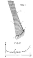
- Figure 1 shows a turbine fin with a root in "Pied-Sapin”.
- Figure 2 shows the stress along a notch of a root in Fir-tree during rotation in nominal speed of the turbine, in the absence of the arrangement of the present invention.
- Figure 3 is a view showing the arrangement according to the invention.
- the view is schematic and partial according to a section parallel to the plane of the fin anchoring disc and made on the side of the root corresponding to the trailing edge fin.
- Figure 4 shows schematically a fin view perpendicular to the plane of the disc with below a diagram representing, for a notch, the evolution of the game between the notch and the corresponding wall of the groove of the side of the trailing edge.
- Figure 1 shows a steam turbine fin 1 with a root 2 in "Pied-sapin" including a plurality of notches such as 3.
- the fin has an edge attack 4 which is the side by where between the steam and a trailing edge 5.
- the fins such as 1 are threaded by their root 2 in complementary geometry grooves made in a rotor disc of the turbine.
- FIG. 2 represents the stress curve c which exists, during nominal disc rotation, along a notch of the root of the fin between the E side corresponding to the leading edge of the fin and that S corresponding to its trailing edge.
- Figure 3 shows the root 2 of a fin 1 in a groove 6 of the rotor disk 7 of a turbine.
- the side marked A corresponds to the lower side and the side marked B corresponds to the upper side.
- the root of the fin shown has four notches 3A, 3B, 3C and 3D.
- This figure 3 shows the root in section by a plane perpendicular to the axis of the disc 7 and on the side of the root corresponding to the trailing edge of the fin, i.e. where a spike usually occurs constraint in the notches.
Landscapes
- Engineering & Computer Science (AREA)
- Mechanical Engineering (AREA)
- General Engineering & Computer Science (AREA)
- Turbine Rotor Nozzle Sealing (AREA)
Description
Claims (4)
- Disposition pour l'écrêtement des pointes de contrainte dans l'ancrage d'une ailette (1) de turbine, comportant une racine (2) dite en Pied-sapin. comprenant des crans (3A, 3B, 3C, 3D) dans une rainure (6) de profil correspondant sur un disque (7), caractérisé par le fait que le profil de chaque cran (3), côté extrados (B) de la racine (2) de l'ailette, est tel que le jeu de montage (J) de la racine dans sa rainure, côté extrados, n'est pas uniforme mais comporte au moins une zone où ce jeu suit une évolution, cette zone correspondant à une zone du cran (3) considéré où, dans le cas d'un montage à jeu constant tout le long dudit cran se produirait, à vitesse de rotation nominale du disque équipé de ses ailettes, une pointe de contrainte par rapport à la contrainte moyenne (m) le long du cran, l'évolution dudit jeu (J2) le long d'une dite zone évoluant dans le même sens que ladite pointe de contrainte.
- Disposition selon la revendication 1, caractérisé en ce que ladite zone est située du côté du bord de fuite.
- Disposition selon la revendication 1, caractérisé en ce que ladite zone est située du côté du bord d'attaque.
- Ailette de turbine, comportant une racine (2) dite en Pied-sapin. comprenant des crans (3A, 3B, 3C, 3D), caractérisé en ce que le profil de chaque cran (3), côté extrados (B) de la racine (2) de l'ailette, est tel que le jeu de montage (J) de la racine dans sa rainure (6), côté extrados, comporte au moins une zone où ce jeu suit une évolution, cette zone correspondant à une zone du cran (3) considéré où, dans le cas d'un montage à jeu constant tout le long dudit cran se produirait, à vitesse de rotation nominale du disque équipé de ses ailettes, une pointe de contrainte par rapport à la contrainte moyenne (m) le long du cran, l'évolution dudit jeu (J2) le long d'une dite zone évoluant dans le même sens que ladite pointe de contrainte.
Applications Claiming Priority (2)
| Application Number | Priority Date | Filing Date | Title |
|---|---|---|---|
| FR9411724 | 1994-09-30 | ||
| FR9411724A FR2725239B1 (fr) | 1994-09-30 | 1994-09-30 | Disposition pour l'ecretement des pointes de contrainte dans l'ancrage d'une ailette de turbine, comportant une racine dite en "pied-sapin" |
Publications (2)
| Publication Number | Publication Date |
|---|---|
| EP0705958A1 EP0705958A1 (fr) | 1996-04-10 |
| EP0705958B1 true EP0705958B1 (fr) | 1998-10-21 |
Family
ID=9467468
Family Applications (1)
| Application Number | Title | Priority Date | Filing Date |
|---|---|---|---|
| EP95402163A Expired - Lifetime EP0705958B1 (fr) | 1994-09-30 | 1995-09-27 | Disposition pour l'écrêtement des pointes de contrainte dans l'ancrage d'une ailette de turbine, comportant une racine dite en "pied-sapin" |
Country Status (5)
| Country | Link |
|---|---|
| US (1) | US5567116A (fr) |
| EP (1) | EP0705958B1 (fr) |
| JP (1) | JPH08105301A (fr) |
| DE (1) | DE69505479T2 (fr) |
| FR (1) | FR2725239B1 (fr) |
Families Citing this family (28)
| Publication number | Priority date | Publication date | Assignee | Title |
|---|---|---|---|---|
| GB9606963D0 (en) * | 1996-04-02 | 1996-06-05 | Rolls Royce Plc | A root attachment for a turbomachine blade |
| WO1997049921A1 (fr) * | 1996-06-21 | 1997-12-31 | Siemens Aktiengesellschaft | Rotor pour une turbomachine avec des pales a monter dans des rainures et pales pour un rotor |
| DE19705323A1 (de) * | 1997-02-12 | 1998-08-27 | Siemens Ag | Reduzierung von lokalen Spannungen in Schaufelfußnuten |
| US6439851B1 (en) * | 2000-12-21 | 2002-08-27 | United Technologies Corporation | Reduced stress rotor blade and disk assembly |
| US7007382B2 (en) * | 2003-07-24 | 2006-03-07 | United Technologies Corporation | Slot machining |
| US7153102B2 (en) * | 2004-05-14 | 2006-12-26 | Pratt & Whitney Canada Corp. | Bladed disk fixing undercut |
| US7156621B2 (en) | 2004-05-14 | 2007-01-02 | Pratt & Whitney Canada Corp. | Blade fixing relief mismatch |
| EP1882084A4 (fr) * | 2005-05-12 | 2013-06-26 | Gen Electric | Coupe arriere d'ailette/disque en queue d'aronde destinee a reduire les contraintes d'ailette/disque (9fa+e, etape 2) |
| JP4870754B2 (ja) * | 2005-05-12 | 2012-02-08 | ゼネラル・エレクトリック・カンパニイ | 動翼/ディスク(7FA+e、第2段)の応力を低減するための動翼/ディスクダブテールバックカット |
| JP4918806B2 (ja) * | 2006-04-06 | 2012-04-18 | 株式会社日立製作所 | タービンロータ及びタービン動翼 |
| JP2009536994A (ja) * | 2006-05-12 | 2009-10-22 | ゼネラル・エレクトリック・カンパニイ | ブレード/ディスクにおける応力低減のためのブレード/ディスクダブテールバックカット(6FA+e、第2段) |
| US20090208339A1 (en) * | 2008-02-15 | 2009-08-20 | United Technologies Corporation | Blade root stress relief |
| US9174292B2 (en) * | 2008-04-16 | 2015-11-03 | United Technologies Corporation | Electro chemical grinding (ECG) quill and method to manufacture a rotor blade retention slot |
| CN101285401B (zh) * | 2008-06-03 | 2010-06-02 | 东方电气集团东方汽轮机有限公司 | 枞树型叶根汽轮机动叶片及其锁口叶片 |
| US7846010B2 (en) * | 2008-09-10 | 2010-12-07 | United Technologies Corporation | Notched grind wheel and method to manufacture a rotor blade retention slot |
| JP5395455B2 (ja) * | 2009-02-20 | 2014-01-22 | 三菱重工業株式会社 | 軸流圧縮機用動翼 |
| US9151167B2 (en) | 2012-02-10 | 2015-10-06 | General Electric Company | Turbine assembly |
| US8974188B2 (en) | 2012-03-06 | 2015-03-10 | Hamilton Sundstrand Corporation | Blade clip |
| US10072507B2 (en) * | 2012-10-25 | 2018-09-11 | United Technologies Corporation | Redundant airfoil attachment |
| WO2014163680A1 (fr) * | 2013-03-10 | 2014-10-09 | Rivers Jonathan M | Élément de fixation d'une aube de turbine à gaz ayant un profil incurvé |
| EP3263910B1 (fr) | 2014-05-05 | 2020-01-08 | Horton, Inc. | Aube en materiau composite pour un ventilateur axial modulaire et procédé de fabrication de celle-ci |
| CN104018888A (zh) * | 2014-06-23 | 2014-09-03 | 中国船舶重工集团公司第七0四研究所 | 用于叶片周向安装的外包枞树型叶根 |
| US10731484B2 (en) | 2014-11-17 | 2020-08-04 | General Electric Company | BLISK rim face undercut |
| US20170074107A1 (en) * | 2015-09-15 | 2017-03-16 | General Electric Company | Blade/disk dovetail backcut for blade disk stress reduction (9e.04, stage 2) |
| US20170356297A1 (en) * | 2016-06-13 | 2017-12-14 | General Electric Company | Lockwire Tab Backcut For Blade Stress Reduction (9E.04) |
| US10895160B1 (en) * | 2017-04-07 | 2021-01-19 | Glenn B. Sinclair | Stress relief via unblended edge radii in blade attachments in gas turbines |
| US12529319B2 (en) | 2024-02-21 | 2026-01-20 | Rtx Corporation | High pressure turbine blade double scarf cut |
| DE102024202463A1 (de) * | 2024-03-15 | 2025-09-18 | Siemens Energy Global GmbH & Co. KG | Turbinenschaufel mit geneigtem Schaufelblatt, Verfahren zur Herstellung und Rotor |
Family Cites Families (7)
| Publication number | Priority date | Publication date | Assignee | Title |
|---|---|---|---|---|
| GB677142A (en) * | 1949-08-24 | 1952-08-13 | Power Jets Res & Dev Ltd | Improved mounting for turbine and like blades |
| US3986793A (en) * | 1974-10-29 | 1976-10-19 | Westinghouse Electric Corporation | Turbine rotating blade |
| US4621979A (en) * | 1979-11-30 | 1986-11-11 | United Technologies Corporation | Fan rotor blades of turbofan engines |
| GB2238581B (en) * | 1989-11-30 | 1994-01-12 | Rolls Royce Plc | Improved attachment of a gas turbine engine blade to a turbine rotor disc |
| US5141401A (en) * | 1990-09-27 | 1992-08-25 | General Electric Company | Stress-relieved rotor blade attachment slot |
| FR2697051B1 (fr) * | 1992-10-21 | 1994-12-02 | Snecma | Rotor de turbomachine comprenant un disque dont le pourtour est occupé par des alvéoles obliques qui alternent avec des dents de section transversale variable. |
| FR2712631B1 (fr) * | 1993-11-19 | 1998-08-21 | Gen Electric | Ailette de rotor et ensemble ailettes-disque de rotor comportant une telle ailette. |
-
1994
- 1994-09-30 FR FR9411724A patent/FR2725239B1/fr not_active Expired - Fee Related
-
1995
- 1995-09-22 US US08/532,103 patent/US5567116A/en not_active Expired - Lifetime
- 1995-09-27 EP EP95402163A patent/EP0705958B1/fr not_active Expired - Lifetime
- 1995-09-27 DE DE69505479T patent/DE69505479T2/de not_active Expired - Lifetime
- 1995-09-28 JP JP7250907A patent/JPH08105301A/ja active Pending
Also Published As
| Publication number | Publication date |
|---|---|
| FR2725239A1 (fr) | 1996-04-05 |
| JPH08105301A (ja) | 1996-04-23 |
| FR2725239B1 (fr) | 1996-11-22 |
| US5567116A (en) | 1996-10-22 |
| DE69505479D1 (de) | 1998-11-26 |
| DE69505479T2 (de) | 1999-04-15 |
| EP0705958A1 (fr) | 1996-04-10 |
Similar Documents
| Publication | Publication Date | Title |
|---|---|---|
| FR2725239A1 (fr) | Disposition pour l'ecretement des pointes de contrainte dans l'ancrage d'une ailette de turbine, comportant une racine dite en "pied-sapin" | |
| CA2755017C (fr) | Compresseur axialo-centrifuge a angle de rake evolutif | |
| EP1452741B1 (fr) | Aube en flèche de turboréacteur | |
| CA2740030C (fr) | Aube de turbine a performances aerodynamiques ameliorees | |
| EP1551215B1 (fr) | Fil de coupe oriente ameliore pour un appareil de coupe de vegetaux | |
| EP1693572B1 (fr) | Prélèvement en tête des roues mobiles de compresseur haute pression de turboréacteur | |
| CA2873942A1 (fr) | Aube de soufflante pour turboreacteur d'avion a profil cambre en sections de pied | |
| WO2019043330A1 (fr) | Aube de redresseur de soufflante de turbomachine, ensemble de turbomachine comprenant une telle aube et turbomachine equipee de ladite aube ou dudit ensemble | |
| FR2689852A1 (fr) | Pale pour voilure tournante d'aéronef, à extrémité en flèche. | |
| FR2814205A1 (fr) | Turbomachine a veine d'ecoulement ameliore | |
| FR2882570A1 (fr) | Dipositif de commande d'aubes a calage variable dans une turbomachine | |
| FR2861128A1 (fr) | Dispositif d'attache d'une aube mobile sur un disque de rotor de turbine dans un turbomachine | |
| EP3123001B1 (fr) | Pièce de révolution pour un rotor de turbomachine, rotor de turbomachine, module de turbomachine et turbomachine associés | |
| EP3976931B1 (fr) | Aube de turbine dotée d'une cavité de fragilisation d'une section frangible | |
| CH233251A (fr) | Compresseur centrifuge. | |
| WO2016146850A1 (fr) | Ventilateur pour automobile amélioré aérodynamiquement et acoustiquement | |
| EP2432684B1 (fr) | Procédé pour l'amélioration de l'efficacité aérodynamique de l'empennage vertical d'un aéronef | |
| EP3191688B1 (fr) | Aube de soufflante | |
| EP0020426A1 (fr) | Grille d'aubes pour turbine. | |
| CA2498321C (fr) | Roue de type francis et machine hydraulique equipee d'une telle roue | |
| FR2784421A1 (fr) | Soufflerie axiale, en particulier pour vehicules a moteur | |
| EP0742077B1 (fr) | Fraise comportant au moins une dent, notamment pour l'usinage de lentilles ophtalmiques | |
| CH177108A (fr) | Pale d'hélice. | |
| EP1491721A1 (fr) | Aube de compresseur de turboréacteur | |
| FR2879684A1 (fr) | Turbomachine comprenant un stator equipe d'aubes de redresseur a calage variable commandees par des biellettes a emmanchement conique |
Legal Events
| Date | Code | Title | Description |
|---|---|---|---|
| PUAI | Public reference made under article 153(3) epc to a published international application that has entered the european phase |
Free format text: ORIGINAL CODE: 0009012 |
|
| AK | Designated contracting states |
Kind code of ref document: A1 Designated state(s): CH DE GB IT LI |
|
| 17P | Request for examination filed |
Effective date: 19960909 |
|
| 17Q | First examination report despatched |
Effective date: 19970902 |
|
| GRAG | Despatch of communication of intention to grant |
Free format text: ORIGINAL CODE: EPIDOS AGRA |
|
| GRAG | Despatch of communication of intention to grant |
Free format text: ORIGINAL CODE: EPIDOS AGRA |
|
| GRAH | Despatch of communication of intention to grant a patent |
Free format text: ORIGINAL CODE: EPIDOS IGRA |
|
| GRAH | Despatch of communication of intention to grant a patent |
Free format text: ORIGINAL CODE: EPIDOS IGRA |
|
| GRAA | (expected) grant |
Free format text: ORIGINAL CODE: 0009210 |
|
| AK | Designated contracting states |
Kind code of ref document: B1 Designated state(s): CH DE GB IT LI |
|
| REG | Reference to a national code |
Ref country code: CH Ref legal event code: EP |
|
| REF | Corresponds to: |
Ref document number: 69505479 Country of ref document: DE Date of ref document: 19981126 |
|
| REG | Reference to a national code |
Ref country code: CH Ref legal event code: NV Representative=s name: CABINET ROLAND NITHARDT CONSEILS EN PROPRIETE INDU |
|
| GBT | Gb: translation of ep patent filed (gb section 77(6)(a)/1977) |
Effective date: 19981111 |
|
| PLBE | No opposition filed within time limit |
Free format text: ORIGINAL CODE: 0009261 |
|
| STAA | Information on the status of an ep patent application or granted ep patent |
Free format text: STATUS: NO OPPOSITION FILED WITHIN TIME LIMIT |
|
| 26N | No opposition filed | ||
| REG | Reference to a national code |
Ref country code: GB Ref legal event code: IF02 |
|
| REG | Reference to a national code |
Ref country code: CH Ref legal event code: PCAR Free format text: CABINET ROLAND NITHARDT CONSEILS EN PROPRIETE INDUSTRIELLE S.A.;Y-PARC RUE GALILEE;1400 YVERDON-LES-BAINS (CH) |
|
| PGFP | Annual fee paid to national office [announced via postgrant information from national office to epo] |
Ref country code: IT Payment date: 20100918 Year of fee payment: 16 |
|
| PG25 | Lapsed in a contracting state [announced via postgrant information from national office to epo] |
Ref country code: IT Free format text: LAPSE BECAUSE OF NON-PAYMENT OF DUE FEES Effective date: 20110927 |
|
| REG | Reference to a national code |
Ref country code: CH Ref legal event code: PUE Owner name: ALSTOM TECHNOLOGY LTD, CH Free format text: FORMER OWNER: ALSTOM POWER SYSTEMS SA, FR Ref country code: CH Ref legal event code: PFA Owner name: ALSTOM POWER SYSTEMS SA, FR Free format text: FORMER OWNER: GEC ALSTHOM ELECTROMECANIQUE SA, FR |
|
| REG | Reference to a national code |
Ref country code: DE Ref legal event code: R082 Ref document number: 69505479 Country of ref document: DE Representative=s name: ROESLER PATENTANWALTSKANZLEI, DE |
|
| REG | Reference to a national code |
Ref country code: DE Ref legal event code: R082 Ref document number: 69505479 Country of ref document: DE Representative=s name: ROESLER PATENTANWALTSKANZLEI, DE Effective date: 20130423 Ref country code: DE Ref legal event code: R081 Ref document number: 69505479 Country of ref document: DE Owner name: ALSTOM TECHNOLOGY LTD., CH Free format text: FORMER OWNER: GEC ALSTHOM ELECTROMECANIQUE S.A., PARIS, FR Effective date: 20130423 |
|
| REG | Reference to a national code |
Ref country code: GB Ref legal event code: 732E Free format text: REGISTERED BETWEEN 20130822 AND 20130828 |
|
| REG | Reference to a national code |
Ref country code: GB Ref legal event code: 732E Free format text: REGISTERED BETWEEN 20130829 AND 20130904 |
|
| PGFP | Annual fee paid to national office [announced via postgrant information from national office to epo] |
Ref country code: CH Payment date: 20140919 Year of fee payment: 20 Ref country code: DE Payment date: 20140922 Year of fee payment: 20 |
|
| PGFP | Annual fee paid to national office [announced via postgrant information from national office to epo] |
Ref country code: GB Payment date: 20140919 Year of fee payment: 20 |
|
| REG | Reference to a national code |
Ref country code: DE Ref legal event code: R071 Ref document number: 69505479 Country of ref document: DE |
|
| REG | Reference to a national code |
Ref country code: CH Ref legal event code: PL |
|
| REG | Reference to a national code |
Ref country code: GB Ref legal event code: PE20 Expiry date: 20150926 |
|
| PG25 | Lapsed in a contracting state [announced via postgrant information from national office to epo] |
Ref country code: GB Free format text: LAPSE BECAUSE OF EXPIRATION OF PROTECTION Effective date: 20150926 |