EP0705476B1 - Loop-shaped pneumatic drive - Google Patents
Loop-shaped pneumatic drive Download PDFInfo
- Publication number
- EP0705476B1 EP0705476B1 EP94920666A EP94920666A EP0705476B1 EP 0705476 B1 EP0705476 B1 EP 0705476B1 EP 94920666 A EP94920666 A EP 94920666A EP 94920666 A EP94920666 A EP 94920666A EP 0705476 B1 EP0705476 B1 EP 0705476B1
- Authority
- EP
- European Patent Office
- Prior art keywords
- strip
- conduit
- loop
- working surface
- orifices
- Prior art date
- Legal status (The legal status is an assumption and is not a legal conclusion. Google has not performed a legal analysis and makes no representation as to the accuracy of the status listed.)
- Expired - Lifetime
Links
Images


Classifications
-
- G—PHYSICS
- G11—INFORMATION STORAGE
- G11B—INFORMATION STORAGE BASED ON RELATIVE MOVEMENT BETWEEN RECORD CARRIER AND TRANSDUCER
- G11B15/00—Driving, starting or stopping record carriers of filamentary or web form; Driving both such record carriers and heads; Guiding such record carriers or containers therefor; Control thereof; Control of operating function
- G11B15/18—Driving; Starting; Stopping; Arrangements for control or regulation thereof
- G11B15/38—Driving record carriers by pneumatic means
Definitions
- the present invention relates to the pneumatic transport of flexible strips of material. More particularly, the invention relates to a drive system that uses fluid, such as air, to support and transport strips of material past a transducer.
- fluid such as air
- Devices which record magnetic or optical signals on magnetic tape are known. Typically, these devices accept tape which is stored on a reel or in a cassette and cause the media to be drawn past a transducer, which is fixed or moving, to allow signals to be read or written on selected regions of the tape. Because relatively long lengths of tape are used for recording significant amounts of information, the tape is typically stored on reels and the tape is drawn past the transducer by a capstan or some other mechanical means. Pulling on the tape puts tension on the media which may cause it to wear, distort or even break in extreme cases such as a malfunction of the device. In addition, the inertia of the mass of tape stored on the reels results in relatively slow acceleration and deceleration of the tape packs on the reels. Rapid acceleration and deceleration also place significant stress on the tape. The amount of time required to accelerate and decelerate the tape packs limits the speed with which information encoded on the tape can be accessed by the drive system.
- the tape may be made thinner so that more tape surface can be stored in a given volume of storage space, such as a cartridge or cassette.
- a given volume of storage space such as a cartridge or cassette.
- tapes having a thickness of 25 ⁇ m or less are common, and 13 ⁇ m thick tape is often used.
- the fragile nature of such tape makes rapid access to random regions of the tape difficult because of the stress that is placed on the tape during rapid acceleration and deceleration of the reels.
- U.S. -A-3,653,568 discloses a pneumatic system for moving an elongated strip of flexible tape around a loop-shaped conduit.
- the tape is moved through a continuous and substantially enclosed passageway or tunnel within the conduit that has dimensions slightly greater than the tape moving therethrough.
- the tape is transported through the tunnel by an air flow which enters the tunnel from both sides of the tapc at four locations spaced around the loop.
- the air flow is exhausted through four pairs of apertures spaced around the loop.
- the pneumatic system disclosed in US-A-3 653 568 has several disadvantages.
- the present invention includes a drive having a loop-shaped conduit having a working surface on its periphery.
- a fluid such as air
- Fluid streams from the orifices support a strip above the working surface and transport it around the periphery of the loop-shaped conduit.
- the strip can be a recording strip and the working surface can be provided on the inner periphery of the loop-shaped conduit.
- the recording strip can be transported around the inner periphery of the conduit in close proximity to the transducer(s), thereby allowing information to be transferred between the transducer(s) and the recording strip.
- the drive described above further includes a linear conduit, also having a working surface, for transporting the strip onto the working surface of the loop-shaped conduit.
- the working surface of the loop-shaped conduit has a second array of orifices so that the strip can be transported around the periphery of the loop-shaped conduit in either direction.
- the drive includes a means for inverting the strip in the drive so that the transducer(s) may read/write on both sides of the strip.
- at least one transducer is positioned within the interior of the area bounded by the loop-shaped conduit so that the strip can pass between it and the working surface of the loop-shaped conduit.
- the array of orifices in the working surface of the loop-shaped conduit can include a linear array of orifices on each side of and parallel to the centerline of the working surface.
- a loop-shaped drive system in a preferred embodiment of the present invention includes a loop-shaped conduit and linear conduit as described above.
- the system also includes a fluid source for providing fluid to the linear and loop-shaped conduits.
- At least one transducer is proximate the working surface of the loop-shaped conduit, whereby information may be transferred between the transducer(s) and the strip as the strip is transported past the transducer(s).
- the present invention also includes a method of transferring information between a loop-shaped drive and a recording strip.
- the method includes the following steps. Fluid streams are directed from an array of orifices in the working surface on the inner periphery of the loop-shaped conduit. The fluid streams support and transport the recording strip around the inner periphery of the loop-shaped conduit. At least one transducer transfers information between the strip and the transducer(s) as the strip is transported past the transducer(s).
- transducer means anything that is capable of sensing the properties of a flexible strip, including, for example, a magnetic or optical read/write head.
- read/write means read and/or write.
- recorded strip means any strip that is capable of storing information.
- proximate and close proximity mean close enough to allow a transducer to read/write on a recording strip.
- the present invention overcomes the disadvantages of the prior art devices by providing a pneumatic device that is able to manipulate a recording strip with directed fluid streams.
- the use of directed fluid streams to support and transport the recording strip provides a distributed motive force on the strip, rather than a localized, mechanical, pulling force, so that the strip is manipulated without substantial lengthwise tension on the media. Because the media is carried by a cushion of fluid, acceleration and deceleration can occur rapidly without producing significant tension on the media in the direction of travel.
- the uniformly distributed directed fluid streams support the recording strip, thereby minimizing wear of the tape due to contact with the device.
- the design of the pneumatic drive according to the present invention allows the recording strip to be accelerated and decelerated very rapidly. As a result, random points on the tape can be accessed very quickly, exceeding the access rates that are typically present when mechanical devices are used.
- Linear conduit 12 comprises working surface 14 having fluid orifices 16 and 18 communicating with a fluid supply manifold within the conduit.
- Orifices 16 and 18 are preferably oriented so that their downstream edges are directed at an angle toward the outer edges of linear conduit 12.
- orifices 16 will generally be activated to cause a flexible recording strip 24 to enter drive 30 and reverse orifices 18 will be activated to cause the strip to exit drive 30.
- Optional edge guides 20 and end wall 22 help physically confine recording strip 24 on linear conduit 12.
- Drive 30 comprises a base 32 supporting a loop-shaped conduit 34 with its inner periphery forming a working surface 46 to support and transport strip 24 as it travels within the drive.
- Working surface 46 contains orifices 38 and 40 for expelling fluid from the manifold (not shown) contained within the interior of loop-shaped conduit 34 to transport strip 24 around the interior of the loop.
- the downstream edges of orifices 38 and 40 are shown angled outwardly relative to the direction of travel of strip 24.
- orifices 38 are activated to cause strip 24 to travel in a clockwise direction and orifices 40 are activated to cause the strip to travel in a counter-clockwise direction, as viewed in Figure 1.
- a first transducer 42 is attached to side wall 50 of drive 30 by guide/support members 48.
- Various mechanisms can be employed to allow transducer 42 to move across the width of working surface 46 in close proximity to strip 24 when it enters drive 30 so that all information tracks on strip 24 can be accessed by the transducer.
- the transfer of information between transducer 42 and strip 24 may be interrupted by the leading or trailing edge of the strip.
- a second transducer 44 may optionally be included as shown in Figure 1.
- Second transducer 44 can be aligned with first transducer 42 to provide for the continuous transfer of information between the transducers and recording strip 24 when read/writing on an information track on the strip.
- Optional side wall 50 and edge guide 52 serve to keep strip 24 from straying off working surface 46.
- system 10 can operate with various other fluids such as water, inert fluorocarbons, and various other gases and gas mixtures.
- linear conduit 12 comprises working surface 14, layers 60, plenum chamber 62, supply manifold 64, and bottom surface 66.
- Plenum chamber 62 communicates with supply manifold 64 via inlet 70 and working surface 14 via orifices 16.
- Linear conduit 12 may be provided on a support 68.
- a fluid source 74 such as a compressor or fan, supplies pressurized fluid to supply manifold 64 via an inlet 72 through bottom surface 66 and optional support 68.
- the direction of the fluid flow within conduit 12 is shown by arrows 76.
- the pressurized fluid exits through orifices 16 in a jet-like flow against strip 24, thereby supporting the strip and causing it to move along working surface 14 in the direction of arrows 78.
- Conduit 12 can include three layers 60 which form a web of flexible material which is supported by support 68, which can be rigid. Fluid enters the first layer 60 from supply manifold 64 via inlet 70. Plenum chamber 62 in the second layer 60 establishes the direction of the fluid flow. The fluid exits via orifice 16 in the third layer 60.
- Layers 60 can be as thin as, for example, about 0,01 mm and can be any flexible material. Layers 60 can be joined or laminated by bonding, welding, or using adhesives. In the alternative, layers 60 can simply be pressed together without bonding. Layers 60 can be pre-coated with an adhesive on the outermost bottom layer and conduit 12 can be attached like adhesive tape to a mounting surface which has ports to communicate with those in the bottom of conduit 12.
- a release layer, such as silicone treated paper, may optionally be included to facilitate storage and unwinding of the article.
- Layers 60 can be formed of plastics, metals, ceramics, or composite materials. To prevent static charge build-up on working surface 14, the working surface can be metallic or conductive plastic.
- the openings in each layer 60 can be formed by any known method including etching, punching, drilling, stamping, or laser cutting. The openings can be perpendicular to or at acute angles with the surface of the layer.
- plenum chamber 62 formed when layers 60 are stacked need not be straight or linear and can have any desired shape.
- layers 60 can be replaced with a single layer having a plurality of holes provided therethrough which allow supply manifold 64 to communicate with working surface 14.
- the holes may be provided by a drill, for example, and should be oriented to roughly approximate the angle provided by the fluid path shown in Figure 2 from inlet 70 to orifice 16.
- the single layer can be rigid or flexible.
- Fluid passes through orifices 16 in working surface 14 in the direction of arrows 86, thereby supporting and transporting strip 24.
- the operation of system 10 can be varied by changing the pattern, direction, angle, shape, and length of orifices 16, the thickness of layers 60, the fluid pressure, and the physical properties of strip 24.
- the operation of the system can also be altered by changing the angle a, shown in Figure 3, at which the fluid exits orifices 16. (For the sake of clarity, orifices 18 are not shown in Figure 3.)
- Directional component 84 of the fluid stream both supports and transports strip 24 while cross-directional component 80, perpendicular to directional component 84, contributes only to the support of the strip.
- Cross-directional component 80 and directional component 84 combine to yield flow direction 82.
- conduit 12 transports strip 24 with less support than if there were a cross-directional component.
- conduit 12 transports strip 24 with increased support.
- conduit 12 holds strip 24 with no transport.
- the fluid stream exiting plenum chamber 62 via orifices 16 creates a controllable gap between working surface 14 of conduit 12 and strip 24.
- the gap is established by balancing and maintaining equilibrium among the forces, including gravity, on strip 24.
- System 10 can operate to transport strip 24 regardless of whether the working surface is in a horizontal or vertical orientation, or at any orientation along the 360° circle of positions.
- directed fluid streams to support and carry recording strip 24 provides a distributed motive force on the strip, rather than a localized pulling force, so that the strip is manipulated without substantial lengthwise or downweb tension on the strip. Because strip 24 flies over a cushion of fluid, acceleration and deceleration can occur rapidly without producing significant tension on the strip.
- the fluid streams shown in Figures 2 and 3 provide a pneumatically induced tension across the width of strip 24, thereby minimizing the flutter and vibration of the strip.
- the fluid streams also provide for exhaust of the fluid from the open working surface without the need for special grooves or other exhaust structures.
- Drive system 10 is also advantageous because it avoids the use of tape guides or capstans, which are major contributors to wear on recording tape by the recording system.
- Drive system 10 operates as follows. Recording strip 24 is positioned on working surface 14 at the end of linear conduit 12 opposite drive 30. Fluid streams originating from orifices 16 are then activated to transport strip 24 toward drive 30. Strip 24 enters loop-shaped conduit 34 via slot 36 in loop-shaped conduit 34. A working surface having a plurality of orifices (not shown) could be provided in slot 36 to facilitate transport of strip 24 into loop-shaped conduit 34. Strip 24 is then transported by fluid streams originating from orifices 38 into the interior of loop-shaped conduit 34. Fluid streams originating from orifices 38 in working surface 46 of loop-shaped conduit 34 transport strip 24 around the inner periphery of loop-shaped conduit 34.
- the rate at which information is transferred between strip 24 and loop-shaped drive 30 depends, among other things, on the speed with which the strip moves with respect to the transducers and the number of such transducers provided.
- the rotational speed of strip 24 in the loop can be as high as 1,800 rev/min or more.
- additional transducers may be provided to increase the rate at which information is transferred between strip 24 and loop drive 30.
- Strip 24 is transported around the interior of loop-shaped conduit 34 as many times as necessary to allow transducer guide/support members 48 to manipulate transducers 42 and 44 across the width of the strip to read/write all of the information tracks on the strip. For example, if there were 200 information tracks on strip 24, 100 revolutions would be required to allow the two transducers to cover all of the tracks, assuming one read/write channels per transducer. If the number of transducers were doubled, the number of revolutions required, and thus the amount of time required, could be halved. Similarly, the number of read/write channels per transducer could be increased, thereby decreasing the number of revolutions required.
- strip 24 It may also be desirable to read/write on strip 24 with the strip moving in a counter-clockwise direction, as viewed in Figure 1. This may be done by activating reverse orifices 40 within loop drive 30 and by providing pneumatic or mechanical means (not shown) near slot 36 in working surface 46 to prevent strip 24 from exiting the interior of loop drive 30.
- the fluid stream would allow information to be transferred between strip 24 and loop drive 30 in the counter-clockwise rotation in the same manner discussed above with respect to the clockwise direction. Strip 24 could then be removed from loop drive 30 by deactivating the fluid stream.
- FIG. 4 An alternative embodiment of the present invention is shown as loop-shaped drive 90 in Figure 4.
- Drive 90 resembles drive 30 with the exception that a second slot 96 is provided in loop-shaped conduit 34 in addition to slot 36.
- a working surface having a plurality of orifices could be provided in slot 96 to facilitate transport of strip 24 in and out of loop-shaped conduit 34.
- Slot 96 allows strip 24 to be moved in one slot and out the other without ever having to change the direction of travel of the strip around the inner periphery of loop-shaped conduit 34.
- a second strip could be brought into one slot while strip 24 exits the loop via the other slot, so that the second strip could be inserted into the loop immediately after the first strip exits the loop.
- the addition of slot 96 also allows loop drive 30 to receive strip 24 from either direction.
- strip 24 It may be desirable to increase the information capacity of strip 24 by allowing for the reading/writing of information on both sides of the strip.
- Strip-inverting loop drive 100 is comprised of loop-shaped conduit 102 having working surface 104 within its inner periphery. Fluid streams originate from orifices (not shown) in working surface 104 just as they do in drives 30 and 90.
- Drive 100 includes transducers 106 and entrance/exit slot 122.
- Two C-shaped inverting curves 108 and 110 having working surfaces 109 and 111, respectively, (also having fluid streams originating from orifices which are not shown) are provided within loop-shaped conduit 102.
- C-shaped inverting curves 108 and 110 are positioned to provide an S-shaped path within loop-shaped conduit 102. Inverting curves 108 and 110 are separated from loop-shaped conduit 102 by gaps 120 and 118, respectively.
- a recording strip 112 having a first recording surface 114 and a second recording surface 116 is shown in Figure 5.
- First recording surface 114 is shown as being notched in Figure 5 solely to illustrate how strip 112 is inverted by inverting curves 108 and 110.
- Drive 100 operates as follows. Recording strip 112 enters drive 100 through slot 122 and is transported around the interior surface of the loop-shaped conduit 102 in a clockwise direction, as shown in Figure 5. Strip 112 then passes by transducers 106 as it continues its clockwise travel around the interior of loop-shaped conduit 102, as indicated by direction arrow 124. Strip 112 may be transported around loop-shaped conduit 102, and thus through gaps 118 and 120, as many times as necessary to allow transducer guide members (not shown) to manipulate transducers 106 to read/write on all of the information tracks across the width of first recording surface 114 on the strip.
- Strip 112 may then be turned over as follows. As strip 112 approaches gap 118, fluid streams emanating from working surface 117 of conduit 119 cause the strip to leave working surface 104 of loop-shaped conduit 102 and instead follow working surface 111 of C-shaped inverting curve 110. As strip 112 approaches the end of inverter 110, it continues onto working surface 109 of C-shaped inverting curve 108. Strip 112 then continues onto working surface 104 of loopshaped conduit 102. Strip l12, now with its first recording surface 114 facing working surface 104 of loop-shaped conduit 102, moves in a counter-clockwise direction, as viewed in Figure 5, and passes through gap 118 in route to transducers 106. Now, however, as strip 112 passes transducers 106, second recording surface 116 is read/written by transducers 106.
- Strip 112 may be transported around loop-shaped conduit 102 in the counter-clockwise direction as many times as desired to allow transducers 106 to read/write on all of the information tracks provided on second recording surface 114 on the strip. Strip 112 can then exit drive 100 via slot 122.
- Inverting curves 108 and 110 can be the same size or not, having the same radius of curvature or not, and can be of any shape which changes the orientation of strip 112.
- Drives 30, 90, and 100 can be constructed from various metals, plastics, composites, etc., but can also be made from any material than can be molded into the shape of a loop.
- the working surfaces of the drives are preferably made of metal, but can also be made of plastics, composites, etc.
- the drives preferably have diameters within the range of from about 1 cm to 2 m. Larger drives will have the capability of employing more transducers and accommodating longer recording strips.
- the shapes of the loop-shaped conduits can be circular, as shown in the Figures, or they can be in the shape of an oval having two parallel sides, an ellipse, in the shape of a rectangle having rounded corners, or irregular.
- no curve within the loop should be so sharp that the recording tape cannot be smoothly transported around the loop by the fluid streams.
- the orifices 16, 18, 38, and 40 are each preferably provided in two linear arrays, one positioned on each side of and parallel to the centerline of the working surface.
- the two arrays can be staggered with respect to each other.
- the orifices can be rectangular and have dimensions of about 1 mm wide by 5 mm long, and can be oriented outwardly in the direction of travel of the recording strip at an angle a of about 30 degrees with respect to the centerline.
- the orifices can have a frequency of about 45 to 180 pairs per meter.
- the recording strip is preferably any sheet which is capable of storing information which can be retrieved by magnetic or optical means.
- the recording strip is preferably high performance video/data magnetic recording tape such as S-VHS.
- the tape may be capable of storing information on either one or both of its sides.
- the strip preferably has a length within the range of from about 12 cm to 5 m and a width within the range of from about 1.25 cm to 20 cm.
- the strip should be about as long as the inner periphery of the loop-shaped conduit with which it is intended to be used in order to minimize access times, but the strip can also be longer or shorter than the inner periphery.
- the strip will typically have a weight per unit area of about 3 mg/cm 2 .
- working surface 46 is shown on the inner periphery of loop-shaped conduit 34, it may instead be provided on the outer periphery. Strip 24 will still be held closely to the working surface, although this may be increasingly difficult to do at high speeds. Multiple working surfaces can also be used to provide special functions such as changing the direction of travel of the strip, bridging gaps, and braking.
- the transducer(s) can be provided on the side of the strip opposite the working surface, or can be provided behind, within, or protruding from the working surface.
- a second working surface could also be positioned on the opposite side of the strip from the first working surface, with the transducer(s) being provided within the second working surface.
- a drive system 10 as shown in Figure 1 was constructed. Loop-shaped drive 30 had a circumference of 25,4 cm and a width of 2,54 cm. A VHS type transducer 42 having a recording track width of 20 ⁇ m was employed. Recording strip 24 was a conventional video recording tape having a thickness of about 25 ⁇ m and a coercivity of about 51,74 kA/m (650 oersteds). Fluid orifices 16 and 38 each consisted of two linear arrays of orifices positioned on either side of and parallel to the centerline of working surfaces 14 and 46, respectively, as shown in Figure 1. Orifices 16 and 38 were oriented at an angle a, as shown in Figure 3, of 30 degrees. The orifices were about 3,5 mm from the edge of strip 24.
- Orifices 16 had a length of about 5 mm and a width of about 1 mm.
- Conduit 12 was 25,4 cm long and had 45 orifices 16.
- the strip of magnetic tape was driven within drive 30 at speeds ranging from 960 cm/s to 1650 cm/s.
- the two speeds bounding that range were achieved with line pressures of 1,1 x 10 5 pascals and 1,5 x 10 5 pascals, respectively, and air flow rates of 3.7 SCMH and 4.9 SCMH, respectively, (standard cubic meter per hour, i.e. m 3 /hour at standard temperature of 0°C and standard pressure of 760 torr, i.e. 1,013 Pa).
- a signal was recorded at a frequency of 4 to 5 MHz with a tape-transducer penetration of about 50 ⁇ m.
- the video still frame image evidenced only a slight horizontal timebase instability and a good RF envelope, indicating its suitability for digital recording. Very good tracking was observed in the horizontal position.
- Loop-shaped drive 30 had a circumference of 38,1 cm and a width of 2,54 cm.
- a data cartridge transducer 42 having a recording track width of 180 ⁇ m and a read track width of 76 ⁇ m was employed.
- Recording strip 24 was a conventional video recording tape having a thickness of about 25 ⁇ m and a coercivity of about 51,74 kA/m (650 oersteds).
- Fluid orifices 16 and 38 were identical to those described in Example 1.
- Conduit 12 was 38,1 cm long and had 67 orifices 16.
- Strip 24 was driven within drive 30 at a speed of 300 cm/s.
- the recording density was about 8000 flux changes per centimeter and the data transfer rate was about 2,4 Megabits per second. Two million passes were made on a single track. No uncorrectable errors were found at the byte level, and very little bit error change was detected.
- Strip 24 and orifices 16 were the same as those in Example 1.
- Strip 24 was transported at a speed of 1270 cm/s with a power consumption of about 10 watts.
- Strip 24 was manually loaded and unloaded and the drive continued to function at all orientations.
- Loop-shaped drive 30 had a circumference of 51,5 cm and a width of 5,08 cm. Drive 30 did not have a transducer.
- Recording strips 24 were conventional video recording tape having thicknesses of 25 ⁇ m and 51 ⁇ m, and coercivities of about 51,74 kA/m (650 oersteds). Recording strips 24 were about 6 mm longer than the circumference of drive 30, so that there was a slight overlap of the strip in the loop.
- a speed of 1270 cm/s was achieved with a line pressure of about 2,8 x 10 4 pascals and an air flow rate of about 0.17-0.2 SCMH. Only a slight amount of wear of strips 24 was observed in the overlapping region after 130 million cycles.
Landscapes
- Advancing Webs (AREA)
- Non-Mechanical Conveyors (AREA)
- Delivering By Means Of Belts And Rollers (AREA)
Abstract
Description
- The present invention relates to the pneumatic transport of flexible strips of material. More particularly, the invention relates to a drive system that uses fluid, such as air, to support and transport strips of material past a transducer.
- Devices which record magnetic or optical signals on magnetic tape are known. Typically, these devices accept tape which is stored on a reel or in a cassette and cause the media to be drawn past a transducer, which is fixed or moving, to allow signals to be read or written on selected regions of the tape. Because relatively long lengths of tape are used for recording significant amounts of information, the tape is typically stored on reels and the tape is drawn past the transducer by a capstan or some other mechanical means. Pulling on the tape puts tension on the media which may cause it to wear, distort or even break in extreme cases such as a malfunction of the device. In addition, the inertia of the mass of tape stored on the reels results in relatively slow acceleration and deceleration of the tape packs on the reels. Rapid acceleration and deceleration also place significant stress on the tape. The amount of time required to accelerate and decelerate the tape packs limits the speed with which information encoded on the tape can be accessed by the drive system.
- As the need for capturing more information in smaller spaces grows, the tape may be made thinner so that more tape surface can be stored in a given volume of storage space, such as a cartridge or cassette. Thus, tapes having a thickness of 25 µm or less are common, and 13 µm thick tape is often used. The fragile nature of such tape makes rapid access to random regions of the tape difficult because of the stress that is placed on the tape during rapid acceleration and deceleration of the reels.
- U.S. -A-3,653,568 discloses a pneumatic system for moving an elongated strip of flexible tape around a loop-shaped conduit. The tape is moved through a continuous and substantially enclosed passageway or tunnel within the conduit that has dimensions slightly greater than the tape moving therethrough. The tape is transported through the tunnel by an air flow which enters the tunnel from both sides of the tapc at four locations spaced around the loop. The air flow is exhausted through four pairs of apertures spaced around the loop.
- The pneumatic system disclosed in US-A-3 653 568 has several disadvantages. First, because only four pairs of output nozzles are provided, the tape is not uniformly supported within the tunnel. As a result of this non-uniform support, the tape will tend to contact the inner surface of the tunnel as it moves around the loop, resulting in wear of the tape. The fact that the tunnel is enclosed, resulting in the need to provide exhaust openings within the tunnel, may also contribute to the non-uniform support of the tape. Second, because the air flow is directed at the tape from both sides of the tape, the air flow from above and below the tape trust be symmetrical. All of the nozzles would probably have to be carefully tuned or calibrated to provide the appropriate air flow pattern within the tunnel. The nozzles might also have to be re-calibrated for different lengths of tape. Third, the duct design is fairly complex.
- It is the object of the present invention to provide a loop-shaped pneumatic drive for flexible strips of material, which drive has a simple construction and operates reliable.
- This object is solved according to the invention by an apparatus as defined in claim 1 and by a method as defined in claim 9. The subclaims refer to preferred embodiments of the invention.
- The present invention includes a drive having a loop-shaped conduit having a working surface on its periphery. A fluid, such as air, is supplied to the conduit and emerges from an array of orifices uniformly distributed throughout the working surface. Fluid streams from the orifices support a strip above the working surface and transport it around the periphery of the loop-shaped conduit. As the strip travels around the periphery of the loop-shaped conduit, it passes in close proximity with at least one transducer, thereby allowing the transducer(s) to sense the properties of the strip. The strip can be a recording strip and the working surface can be provided on the inner periphery of the loop-shaped conduit. Thus, the recording strip can be transported around the inner periphery of the conduit in close proximity to the transducer(s), thereby allowing information to be transferred between the transducer(s) and the recording strip.
- In one embodiment, the drive described above further includes a linear conduit, also having a working surface, for transporting the strip onto the working surface of the loop-shaped conduit. In another embodiment. the working surface of the loop-shaped conduit has a second array of orifices so that the strip can be transported around the periphery of the loop-shaped conduit in either direction. In yet another embodiment, the drive includes a means for inverting the strip in the drive so that the transducer(s) may read/write on both sides of the strip. In still yet another embodiment, at least one transducer is positioned within the interior of the area bounded by the loop-shaped conduit so that the strip can pass between it and the working surface of the loop-shaped conduit. In still another embodiment, the array of orifices in the working surface of the loop-shaped conduit can include a linear array of orifices on each side of and parallel to the centerline of the working surface.
- In a preferred embodiment of the present invention a loop-shaped drive system includes a loop-shaped conduit and linear conduit as described above. The system also includes a fluid source for providing fluid to the linear and loop-shaped conduits. At least one transducer is proximate the working surface of the loop-shaped conduit, whereby information may be transferred between the transducer(s) and the strip as the strip is transported past the transducer(s).
- The present invention also includes a method of transferring information between a loop-shaped drive and a recording strip. The method includes the following steps. Fluid streams are directed from an array of orifices in the working surface on the inner periphery of the loop-shaped conduit. The fluid streams support and transport the recording strip around the inner periphery of the loop-shaped conduit. At least one transducer transfers information between the strip and the transducer(s) as the strip is transported past the transducer(s).
- As used herein, the term "transducer" means anything that is capable of sensing the properties of a flexible strip, including, for example, a magnetic or optical read/write head. The term "read/write" means read and/or write. The term "recorded strip" means any strip that is capable of storing information. The terms "proximate" and "close proximity" mean close enough to allow a transducer to read/write on a recording strip.
- The present invention overcomes the disadvantages of the prior art devices by providing a pneumatic device that is able to manipulate a recording strip with directed fluid streams. The use of directed fluid streams to support and transport the recording strip provides a distributed motive force on the strip, rather than a localized, mechanical, pulling force, so that the strip is manipulated without substantial lengthwise tension on the media. Because the media is carried by a cushion of fluid, acceleration and deceleration can occur rapidly without producing significant tension on the media in the direction of travel. The uniformly distributed directed fluid streams support the recording strip, thereby minimizing wear of the tape due to contact with the device.
- The design of the pneumatic drive according to the present invention allows the recording strip to be accelerated and decelerated very rapidly. As a result, random points on the tape can be accessed very quickly, exceeding the access rates that are typically present when mechanical devices are used.
- Hereinbelow preferred embodiments of the invention will be explained in more detail refering to the drawing in which
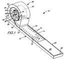
- Figure 1 is a schematic perspective view of a drive system according to the present invention,
- Figure 2 is a schematic cross-sectional side view of the linear conduit shown in Figure 1,
- Figure 3 is a schematic top view of the linear conduit shown in Figure 2,
- Figure 4 is a schematic perspective view of a loop-shaped drive according to an alternative embodiment of the present invention, and
- Figure 5 is a schematic side view of a strip-inverting loop-shaped drive according to the present invention.
- The invention can be illustrated by reference to Figure 1 wherein a
simple drive system 10 comprising a loop-shaped drive 30 and a supply conduit such aslinear supply conduit 12 is shown.Linear conduit 12 comprises workingsurface 14 havingfluid orifices linear conduit 12. Thus orifices 16 will generally be activated to cause aflexible recording strip 24 to enterdrive 30 and reverseorifices 18 will be activated to cause the strip to exitdrive 30. Optional edge guides 20 andend wall 22 help physically confinerecording strip 24 onlinear conduit 12. -
Drive 30 comprises a base 32 supporting a loop-shapedconduit 34 with its inner periphery forming a workingsurface 46 to support andtransport strip 24 as it travels within the drive. Workingsurface 46 containsorifices conduit 34 to transportstrip 24 around the interior of the loop. As withlinear conduit 12, the downstream edges oforifices strip 24. Thus,orifices 38 are activated to causestrip 24 to travel in a clockwise direction andorifices 40 are activated to cause the strip to travel in a counter-clockwise direction, as viewed in Figure 1. - A
first transducer 42 is attached toside wall 50 ofdrive 30 by guide/support members 48. Various mechanisms can be employed to allowtransducer 42 to move across the width of workingsurface 46 in close proximity to strip 24 when it enters drive 30 so that all information tracks onstrip 24 can be accessed by the transducer. The transfer of information betweentransducer 42 andstrip 24 may be interrupted by the leading or trailing edge of the strip. Thus, asecond transducer 44 may optionally be included as shown in Figure 1.Second transducer 44 can be aligned withfirst transducer 42 to provide for the continuous transfer of information between the transducers andrecording strip 24 when read/writing on an information track on the strip. -
Optional side wall 50 and edge guide 52 serve to keepstrip 24 from straying off workingsurface 46. Although the illustrated embodiments included herein are described as using air,system 10 can operate with various other fluids such as water, inert fluorocarbons, and various other gases and gas mixtures. - The following discussion regarding
linear conduit 12 also applies to loop-shapedconduit 34. As shown in Figure 2,linear conduit 12 comprises workingsurface 14, layers 60,plenum chamber 62,supply manifold 64, andbottom surface 66.Plenum chamber 62 communicates withsupply manifold 64 viainlet 70 and workingsurface 14 viaorifices 16.Linear conduit 12 may be provided on asupport 68. Afluid source 74, such as a compressor or fan, supplies pressurized fluid to supplymanifold 64 via aninlet 72 throughbottom surface 66 andoptional support 68. The direction of the fluid flow withinconduit 12 is shown byarrows 76. The pressurized fluid exits throughorifices 16 in a jet-like flow againststrip 24, thereby supporting the strip and causing it to move along workingsurface 14 in the direction ofarrows 78. -
Conduit 12 can include threelayers 60 which form a web of flexible material which is supported bysupport 68, which can be rigid. Fluid enters thefirst layer 60 fromsupply manifold 64 viainlet 70.Plenum chamber 62 in thesecond layer 60 establishes the direction of the fluid flow. The fluid exits viaorifice 16 in thethird layer 60.Layers 60 can be as thin as, for example, about 0,01 mm and can be any flexible material.Layers 60 can be joined or laminated by bonding, welding, or using adhesives. In the alternative, layers 60 can simply be pressed together without bonding.Layers 60 can be pre-coated with an adhesive on the outermost bottom layer andconduit 12 can be attached like adhesive tape to a mounting surface which has ports to communicate with those in the bottom ofconduit 12. A release layer, such as silicone treated paper, may optionally be included to facilitate storage and unwinding of the article. -
Layers 60 can be formed of plastics, metals, ceramics, or composite materials. To prevent static charge build-up on workingsurface 14, the working surface can be metallic or conductive plastic. The openings in eachlayer 60 can be formed by any known method including etching, punching, drilling, stamping, or laser cutting. The openings can be perpendicular to or at acute angles with the surface of the layer. Also,plenum chamber 62 formed whenlayers 60 are stacked need not be straight or linear and can have any desired shape. - In the alternative, layers 60 can be replaced with a single layer having a plurality of holes provided therethrough which allow
supply manifold 64 to communicate with workingsurface 14. The holes may be provided by a drill, for example, and should be oriented to roughly approximate the angle provided by the fluid path shown in Figure 2 frominlet 70 toorifice 16. The single layer can be rigid or flexible. - Fluid passes through
orifices 16 in workingsurface 14 in the direction ofarrows 86, thereby supporting and transportingstrip 24. The operation ofsystem 10 can be varied by changing the pattern, direction, angle, shape, and length oforifices 16, the thickness oflayers 60, the fluid pressure, and the physical properties ofstrip 24. The operation of the system can also be altered by changing the angle a, shown in Figure 3, at which the fluid exitsorifices 16. (For the sake of clarity,orifices 18 are not shown in Figure 3.)Directional component 84 of the fluid stream both supports and transportsstrip 24 whilecross-directional component 80, perpendicular todirectional component 84, contributes only to the support of the strip.Cross-directional component 80 anddirectional component 84 combine to yieldflow direction 82. When the fluid exits with nocross-directional component 80,conduit 12 transports strip 24 with less support than if there were a cross-directional component. When the fluid exits with some cross-directional component,conduit 12 transports strip 24 with increased support. When the fluid exits with nodirectional component 84,conduit 12 holdsstrip 24 with no transport. - The fluid stream exiting
plenum chamber 62 viaorifices 16 creates a controllable gap between workingsurface 14 ofconduit 12 andstrip 24. The gap is established by balancing and maintaining equilibrium among the forces, including gravity, onstrip 24.System 10 can operate to transportstrip 24 regardless of whether the working surface is in a horizontal or vertical orientation, or at any orientation along the 360° circle of positions. - The use of directed fluid streams to support and carry
recording strip 24 provides a distributed motive force on the strip, rather than a localized pulling force, so that the strip is manipulated without substantial lengthwise or downweb tension on the strip. Becausestrip 24 flies over a cushion of fluid, acceleration and deceleration can occur rapidly without producing significant tension on the strip. - It has been found that a relatively stable separation between the strip and the working surface is possible with the configurations described herein. The strip can be prevented from touching the working surface while still being held closely thereto as the strip follows a straight or curved path. The stable separation between the strip and the working surface is also maintained as the strip moves past the transducer(s).
- The fluid streams shown in Figures 2 and 3 provide a pneumatically induced tension across the width of
strip 24, thereby minimizing the flutter and vibration of the strip. The fluid streams also provide for exhaust of the fluid from the open working surface without the need for special grooves or other exhaust structures.Drive system 10 is also advantageous because it avoids the use of tape guides or capstans, which are major contributors to wear on recording tape by the recording system. -
Drive system 10 operates as follows. Recordingstrip 24 is positioned on workingsurface 14 at the end oflinear conduit 12opposite drive 30. Fluid streams originating fromorifices 16 are then activated to transportstrip 24 towarddrive 30.Strip 24 enters loop-shapedconduit 34 viaslot 36 in loop-shapedconduit 34. A working surface having a plurality of orifices (not shown) could be provided inslot 36 to facilitate transport ofstrip 24 into loop-shapedconduit 34.Strip 24 is then transported by fluid streams originating fromorifices 38 into the interior of loop-shapedconduit 34. Fluid streams originating fromorifices 38 in workingsurface 46 of loop-shapedconduit 34transport strip 24 around the inner periphery of loop-shapedconduit 34. - The rate at which information is transferred between
strip 24 and loop-shapeddrive 30 depends, among other things, on the speed with which the strip moves with respect to the transducers and the number of such transducers provided. The rotational speed ofstrip 24 in the loop can be as high as 1,800 rev/min or more. Although twotransducers strip 24 andloop drive 30. -
Strip 24 is transported around the interior of loop-shapedconduit 34 as many times as necessary to allow transducer guide/support members 48 to manipulatetransducers strip - Once the desired information has been transferred between
strip 24 andloop drive 30, fluid streams originating fromreverse orifices 40 are activated, and the fluid streams originating fromorifices 38 are deactivated, to stop the clockwise rotation (as viewed in Figure 1) of the strip within the loop drive.Strip 24 is then transported by fluid streams originating fromreverse orifices 40 back out of loop drive 30 throughslot 36. Fluid streams fromreverse orifices 18 on workingsurface 14 thentransport strip 24 completely out ofloop drive 30 and towardend wall 22 oflinear conduit 12. - It may also be desirable to read/write on
strip 24 with the strip moving in a counter-clockwise direction, as viewed in Figure 1. This may be done by activatingreverse orifices 40 withinloop drive 30 and by providing pneumatic or mechanical means (not shown) nearslot 36 in workingsurface 46 to preventstrip 24 from exiting the interior ofloop drive 30. Thus, the fluid stream would allow information to be transferred betweenstrip 24 and loop drive 30 in the counter-clockwise rotation in the same manner discussed above with respect to the clockwise direction.Strip 24 could then be removed from loop drive 30 by deactivating the fluid stream. - An alternative embodiment of the present invention is shown as loop-shaped
drive 90 in Figure 4.Drive 90 resembles drive 30 with the exception that asecond slot 96 is provided in loop-shapedconduit 34 in addition toslot 36. Likeslot 36, a working surface having a plurality of orifices (not shown) could be provided inslot 96 to facilitate transport ofstrip 24 in and out of loop-shapedconduit 34.Slot 96 allowsstrip 24 to be moved in one slot and out the other without ever having to change the direction of travel of the strip around the inner periphery of loop-shapedconduit 34. Thus, a second strip could be brought into one slot whilestrip 24 exits the loop via the other slot, so that the second strip could be inserted into the loop immediately after the first strip exits the loop. The addition ofslot 96 also allowsloop drive 30 to receivestrip 24 from either direction. - It may be desirable to increase the information capacity of
strip 24 by allowing for the reading/writing of information on both sides of the strip. Thus it may be desirable to provide a mechanism indrives strip 24 withinloop drive 30 so that both sides (in turn) of the strip can be read/written by transducers within the loop. - One such device for inverting
strip 24 is shown as strip-inverting loop-shapeddrive 100 in Figure 5. Strip-invertingloop drive 100 is comprised of loop-shapedconduit 102 having workingsurface 104 within its inner periphery. Fluid streams originate from orifices (not shown) in workingsurface 104 just as they do indrives transducers 106 and entrance/exit slot 122. Two C-shaped inverting curves 108 and 110 having workingsurfaces conduit 102. C-shaped inverting curves 108 and 110 are positioned to provide an S-shaped path within loop-shapedconduit 102. Inverting curves 108 and 110 are separated from loop-shapedconduit 102 bygaps - A
recording strip 112 having afirst recording surface 114 and asecond recording surface 116 is shown in Figure 5.First recording surface 114 is shown as being notched in Figure 5 solely to illustrate howstrip 112 is inverted by invertingcurves - Drive 100 operates as follows.
Recording strip 112 enters drive 100 throughslot 122 and is transported around the interior surface of the loop-shapedconduit 102 in a clockwise direction, as shown in Figure 5.Strip 112 then passes bytransducers 106 as it continues its clockwise travel around the interior of loop-shapedconduit 102, as indicated bydirection arrow 124.Strip 112 may be transported around loop-shapedconduit 102, and thus throughgaps transducers 106 to read/write on all of the information tracks across the width offirst recording surface 114 on the strip. -
Strip 112 may then be turned over as follows. Asstrip 112 approachesgap 118, fluid streams emanating from workingsurface 117 ofconduit 119 cause the strip to leave workingsurface 104 of loop-shapedconduit 102 and instead follow workingsurface 111 of C-shapedinverting curve 110. Asstrip 112 approaches the end ofinverter 110, it continues onto workingsurface 109 of C-shapedinverting curve 108.Strip 112 then continues onto workingsurface 104 ofloopshaped conduit 102. Strip l12, now with itsfirst recording surface 114 facing workingsurface 104 of loop-shapedconduit 102, moves in a counter-clockwise direction, as viewed in Figure 5, and passes throughgap 118 in route to transducers 106. Now, however, asstrip 112passes transducers 106,second recording surface 116 is read/written bytransducers 106. -
Strip 112 may be transported around loop-shapedconduit 102 in the counter-clockwise direction as many times as desired to allowtransducers 106 to read/write on all of the information tracks provided onsecond recording surface 114 on the strip.Strip 112 can then exitdrive 100 viaslot 122. - Inverting curves 108 and 110 can be the same size or not, having the same radius of curvature or not, and can be of any shape which changes the orientation of
strip 112. -
Drives - The shapes of the loop-shaped conduits can be circular, as shown in the Figures, or they can be in the shape of an oval having two parallel sides, an ellipse, in the shape of a rectangle having rounded corners, or irregular. However, no curve within the loop should be so sharp that the recording tape cannot be smoothly transported around the loop by the fluid streams.
- The
orifices - The recording strip is preferably any sheet which is capable of storing information which can be retrieved by magnetic or optical means. The recording strip is preferably high performance video/data magnetic recording tape such as S-VHS. The tape may be capable of storing information on either one or both of its sides. The strip preferably has a length within the range of from about 12 cm to 5 m and a width within the range of from about 1.25 cm to 20 cm. The strip should be about as long as the inner periphery of the loop-shaped conduit with which it is intended to be used in order to minimize access times, but the strip can also be longer or shorter than the inner periphery. The strip will typically have a weight per unit area of about 3 mg/cm2.
- Although working
surface 46 is shown on the inner periphery of loop-shapedconduit 34, it may instead be provided on the outer periphery.Strip 24 will still be held closely to the working surface, although this may be increasingly difficult to do at high speeds. Multiple working surfaces can also be used to provide special functions such as changing the direction of travel of the strip, bridging gaps, and braking. - The transducer(s) can be provided on the side of the strip opposite the working surface, or can be provided behind, within, or protruding from the working surface. A second working surface could also be positioned on the opposite side of the strip from the first working surface, with the transducer(s) being provided within the second working surface.
- It will be obvious to those skilled in the art that having a device such as the one disclosed herein that can precisely read and write information on a strip and which leaves one surface of the strip exposed can have applications in imaging, photography, x-ray, and other display or image gathering devices. Although the invention has been described for use with flexible recording strips, the invention can be used with any flexible strip of material that has properties which can be sensed by a transducer.
- The present invention will now be further illustrated by the following nonlimiting examples. All measurements are approximate.
- A
drive system 10 as shown in Figure 1 was constructed. Loop-shapeddrive 30 had a circumference of 25,4 cm and a width of 2,54 cm. AVHS type transducer 42 having a recording track width of 20 µm was employed. Recordingstrip 24 was a conventional video recording tape having a thickness of about 25 µm and a coercivity of about 51,74 kA/m (650 oersteds).Fluid orifices surfaces strip 24. There were about 90 pairs of orifices per column per meter. The two columns of orifices were staggered as shown in Figure 3.Orifices 16 had a length of about 5 mm and a width of about 1 mm.Conduit 12 was 25,4 cm long and had 45orifices 16. - The strip of magnetic tape was driven within
drive 30 at speeds ranging from 960 cm/s to 1650 cm/s. The two speeds bounding that range were achieved with line pressures of 1,1 x 10⁵ pascals and 1,5 x 10⁵ pascals, respectively, and air flow rates of 3.7 SCMH and 4.9 SCMH, respectively, (standard cubic meter per hour, i.e. m3/hour at standard temperature of 0°C and standard pressure of 760 torr, i.e. 1,013 Pa). - A signal was recorded at a frequency of 4 to 5 MHz with a tape-transducer penetration of about 50 µm. The video still frame image evidenced only a slight horizontal timebase instability and a good RF envelope, indicating its suitability for digital recording. Very good tracking was observed in the horizontal position.
- A
drive system 10 as shown in Figure 1 was constructed. Loop-shapeddrive 30 had a circumference of 38,1 cm and a width of 2,54 cm. Adata cartridge transducer 42 having a recording track width of 180 µm and a read track width of 76 µm was employed. Recordingstrip 24 was a conventional video recording tape having a thickness of about 25 µm and a coercivity of about 51,74 kA/m (650 oersteds).Fluid orifices Conduit 12 was 38,1 cm long and had 67orifices 16. -
Strip 24 was driven withindrive 30 at a speed of 300 cm/s. The recording density was about 8000 flux changes per centimeter and the data transfer rate was about 2,4 Megabits per second. Two million passes were made on a single track. No uncorrectable errors were found at the byte level, and very little bit error change was detected. - A loop-shaped
drive 30 in the shape of an oval having two parallel sides, was constructed having an inner periphery 25,4 cm long and a width of 2,54 cm.Drive 30 did not have a transducer.Strip 24 andorifices 16 were the same as those in Example 1.Strip 24 was transported at a speed of 1270 cm/s with a power consumption of about 10 watts.Strip 24 was manually loaded and unloaded and the drive continued to function at all orientations. - A
drive system 10 as shown in Figure 1 was constructed. Loop-shapeddrive 30 had a circumference of 51,5 cm and a width of 5,08 cm.Drive 30 did not have a transducer. Recording strips 24 were conventional video recording tape having thicknesses of 25 µm and 51 µm, and coercivities of about 51,74 kA/m (650 oersteds). Recording strips 24 were about 6 mm longer than the circumference ofdrive 30, so that there was a slight overlap of the strip in the loop. - A speed of 1270 cm/s was achieved with a line pressure of about 2,8 x 10⁴ pascals and an air flow rate of about 0.17-0.2 SCMH. Only a slight amount of wear of
strips 24 was observed in the overlapping region after 130 million cycles.
Claims (10)
- Apparatus for sensing the properties of a flexible strip comprising a loop-shaped drive means (30) comprising a loop-shaped conduit (34) defined by an inner peripheral wall and an outer peripheral wall, each of said peripheral walls having an interior surface within said conduit (34) and an exterior surface outside of said conduit (34), said conduit (34) having a working surface (46),
characterized in that
said working surface (46) is provided on one of said exterior surfaces, said working surface (46) having a plurality of orifices (38) uniformly distributed throughout and provided at an angle (a) to a longitudinal centerline of the working surface (46) for directing fluid, supplied to said conduit (34), to provide a cross-directional component (80) to support a flexible strip (24) adjacent to and spaced from said working surface (46) and to provide a directional component (84) to transport said strip (24) around said one of said exterior surfaces in at least a first direction and into close proximity with at least one transducer (42), whereby said at least one transducer (42) can sense the properties of said strip (24). - Apparatus according to claim 1, wherein the apparatus senses the properties of a flexible recording strip (24) by reading/writing said recording strip (24) and wherein said transducer (42) can read/write information on said recording strip (24).
- Apparatus according to claim 1 or 2, further comprising a linear conduit (12) having a second working surface (14), said second working surface (14) having a second plurality of orifices (16) uniformly distributed throughout for directing fluid, supplied to said linear conduit (12), to support and transport said strip (24), wherein said linear conduit (12) is oriented so as to transport said strip (24) onto said working surface (46) of said loop-shaped conduit (34) through a slot (36) provided in said loop-shaped conduit (34).
- Apparatus according to any one of claims 1 to 3 characterized in that said working surface (46) on said exterior surface of said loop-shaped conduit (34) has a second plurality of orifices (40) for directing fluid to support and transport said strip (24) in a second direction, wherein said drive means (30) can transport said strip (24) around said exterior surface in both directions.
- Apparatus according to any one of claims 1, 3 or 4 characterized by comprising means (108,110) within said drive means (30) for changing the side of said strip (24) that faces said working surface (46) on said exterior surface of said loop-shaped conduit (34), thereby allowing information on both sides of said strip (24) to be transferred between said at least one transducer (42) and said strip (24).
- Apparatus according to any one of claims 1 to 5 characterized in that said plurality of orifices in said working surface (46) on said exterior surface of said loop-shaped conduit (34) comprises two linear arrays of orifices, wherein one linear array is provided on each side of and parallel to the centerline of said working surface (46) to transport said strip (24) in said first direction.
- Apparatus according to any one of claims 1 to 6 characterized by a fluid source (74) for providing said fluid to said loop-shaped conduit (34).
- Apparatus according to any one of claims 1 or 3 to 4 characterized in that said strip (24) is a magnetic recording strip and has a plurality of available recording tracks, and said at least one transducer (42) is a magnetic head, wherein a second magnetic head (44) is included, said heads (42,44) being aligned to provide a continuous transfer of information between said heads (42,44) and said recording strip (24).
- A method of sensing the properties of a flexible strip using a loop-shaped drive means (30) which comprises a loop-shaped conduit (34) defined by an inner peripheral wall and an outer peripheral wall, each of said peripheral walls having an interior surface within said conduit (34) and an external surface outside of said conduit (34), said conduit (34) having a working surface (46) on one of said exterior surfaces, the method comprising the steps of:- directing fluid, supplied to said conduit (34), through a first plurality of orifices (38) uniformly distributed throughout and provided at an angle (a) to a longitudinal centerline of said working surface (46), for- providing a cross-directional component (80) to support said strip (24) adjacent to and spaced from said working surface (46) and for- providing a directional component (84) to transport said strip (24) around said one of exterior surfaces of said conduit (34), and- sensing the properties of said strip (24) as said strip (24) is transported past at least one transducer (42).
- Method of claim 9 wherein the properties of a flexible recording strip (24) are sensed by reading/ writing said recording strip (24) and wherein said transducer (42) can read/write information on said recording strip (24).
Applications Claiming Priority (3)
| Application Number | Priority Date | Filing Date | Title |
|---|---|---|---|
| US81433 | 1993-06-22 | ||
| US08/081,433 US5432653A (en) | 1993-06-22 | 1993-06-22 | Loop-shaped pneumatic drive |
| PCT/US1994/004861 WO1995000951A1 (en) | 1993-06-22 | 1994-05-03 | Loop-shaped pneumatic drive |
Publications (2)
| Publication Number | Publication Date |
|---|---|
| EP0705476A1 EP0705476A1 (en) | 1996-04-10 |
| EP0705476B1 true EP0705476B1 (en) | 1997-07-09 |
Family
ID=22164132
Family Applications (1)
| Application Number | Title | Priority Date | Filing Date |
|---|---|---|---|
| EP94920666A Expired - Lifetime EP0705476B1 (en) | 1993-06-22 | 1994-05-03 | Loop-shaped pneumatic drive |
Country Status (10)
| Country | Link |
|---|---|
| US (1) | US5432653A (en) |
| EP (1) | EP0705476B1 (en) |
| JP (1) | JPH08511894A (en) |
| KR (1) | KR960703260A (en) |
| CN (1) | CN1125493A (en) |
| AU (1) | AU7137294A (en) |
| DE (1) | DE69404150T2 (en) |
| IL (1) | IL109725A0 (en) |
| MX (1) | MX9404285A (en) |
| WO (1) | WO1995000951A1 (en) |
Families Citing this family (1)
| Publication number | Priority date | Publication date | Assignee | Title |
|---|---|---|---|---|
| US6047873A (en) * | 1999-03-22 | 2000-04-11 | Kinematic Automation, Inc. | Web feed guide apparatus |
Family Cites Families (56)
| Publication number | Priority date | Publication date | Assignee | Title |
|---|---|---|---|---|
| US3127120A (en) * | 1964-03-31 | Tape transport mechanism | ||
| CA615924A (en) * | 1961-03-07 | Electric And Musical Industries Limited | Apparatus for driving webs | |
| US2612566A (en) * | 1951-06-05 | 1952-09-30 | Bell Telephone Labor Inc | Magnetic recording and reproducing system |
| US2905768A (en) * | 1954-09-24 | 1959-09-22 | Ibm | Air head |
| US2913536A (en) * | 1956-02-08 | 1959-11-17 | Lab For Electronics Inc | Magnetic head assemblies |
| US2816757A (en) * | 1956-07-16 | 1957-12-17 | Monroe Calculating Machine | Pneumatically controlled tape transporter |
| US3106355A (en) * | 1960-07-05 | 1963-10-08 | Rca Corp | Apparatus for handling and storing strip media |
| US3231165A (en) * | 1961-12-02 | 1966-01-25 | Svenska Flaektfabriken Ab | Method and apparatus for stabilizing an air-borne web |
| US3103850A (en) * | 1961-12-14 | 1963-09-17 | Ibm | Pneumatically operated document sensing station |
| US3134527A (en) * | 1962-01-02 | 1964-05-26 | Ampex | Tape driving means |
| US3198515A (en) * | 1963-04-05 | 1965-08-03 | Robert C Pitney | Aerodynamic document handling apparatus |
| US3180688A (en) * | 1963-05-22 | 1965-04-27 | Rudolph E Futer | Air-lift conveying of solids |
| US3270933A (en) * | 1963-12-20 | 1966-09-06 | Minnesota Mining & Mfg | Air-cushioned tape guide |
| NL302736A (en) * | 1963-12-30 | |||
| US3418434A (en) * | 1965-02-12 | 1968-12-24 | Cons Electrodynamics Corp | Pneumatic means for maintaining tape in contact with transducer |
| US3347437A (en) * | 1965-07-28 | 1967-10-17 | Charles D Rush | Tape guidance system |
| DE1499998A1 (en) * | 1965-12-07 | 1970-07-23 | Vyzk Ustav Matemat Stroju | Method and device for driving or braking a recording belt |
| US3428514A (en) * | 1966-05-18 | 1969-02-18 | Ritter Pfaudler Corp | Spherical reflectant organic polymer article and process |
| US3405977A (en) * | 1966-08-04 | 1968-10-15 | Sperry Rand Corp | All-fluid unit record accelerator |
| FR1527937A (en) * | 1967-03-31 | 1968-06-07 | Saint Gobain | Device for transporting a sheet-shaped material on a gas cushion |
| US3471971A (en) * | 1967-09-28 | 1969-10-14 | Moscow K Richmond | Door operator |
| US3645581A (en) * | 1968-11-26 | 1972-02-29 | Ind Modular Systems Corp | Apparatus and method for handling and treating articles |
| GB1288686A (en) * | 1969-06-11 | 1972-09-13 | ||
| US3576282A (en) * | 1969-06-30 | 1971-04-27 | Ibm | Pneumatically biased tape loading |
| US3614168A (en) * | 1969-09-30 | 1971-10-19 | Bowles Fluidics Corp | Bernoulli conveyor |
| US3620430A (en) * | 1970-03-05 | 1971-11-16 | Ibm | Constant mass flow pressurized air bearing |
| US3623775A (en) * | 1970-06-30 | 1971-11-30 | Ibm | Loading and unloading an endless web in a cartridge |
| US3653568A (en) * | 1970-07-02 | 1972-04-04 | Ibm | Tape transport mechanism |
| US3678216A (en) * | 1970-07-14 | 1972-07-18 | Mobil Oil Corp | Air distributor for obtaining uniform head-tape contact in magnetic tape transport |
| US3705413A (en) * | 1970-12-28 | 1972-12-05 | Ibm | Video strip file and system |
| US3708136A (en) * | 1971-01-21 | 1973-01-02 | Ibm | Magnetic tape unit having a pneumatic reel hub |
| US3718371A (en) * | 1971-08-25 | 1973-02-27 | Ind Modular Syst Corp | Fluid bearing track structure and components thereof |
| US3796393A (en) * | 1972-04-19 | 1974-03-12 | Ibm | Pneumatic-photoelectric transducer in a magnetic tape unit |
| US3912144A (en) * | 1973-07-02 | 1975-10-14 | Ibm | Tape transport for magnetic recording with a rotating head |
| US3918706A (en) * | 1974-06-24 | 1975-11-11 | Ibm | Pneumatic sheet transport and alignment mechanism |
| US4015880A (en) * | 1975-05-21 | 1977-04-05 | The United States Of America As Represented By The Secretary Of The Air Force | Multiple level fluid bearing track assembly |
| US4055340A (en) * | 1975-11-28 | 1977-10-25 | Xerox Corporation | Assisted pneumatic transport and registration apparatus |
| US4059260A (en) * | 1975-12-08 | 1977-11-22 | Xerox Corporation | Document handling apparatus |
| US4003568A (en) * | 1975-12-08 | 1977-01-18 | Xerox Corporation | Fluid conveyer |
| USRE32284E (en) * | 1976-01-15 | 1986-11-11 | Xerox Corporation | Document storage and transport apparatus |
| US4081201A (en) * | 1976-12-27 | 1978-03-28 | International Business Machines Corporation | Wafer air film transportation system |
| US4144618A (en) * | 1977-06-22 | 1979-03-20 | E. I. Du Pont De Nemours And Company | Material converger |
| US4411503A (en) * | 1978-05-23 | 1983-10-25 | Harris Corporation | Air-platen bearing |
| US4568223A (en) * | 1978-10-02 | 1986-02-04 | Precision Metal Fabricators, Inc. | Air table system |
| US4299518A (en) * | 1980-03-03 | 1981-11-10 | Texas Instruments Incorporated | Manufacturing work station |
| US4337885A (en) * | 1980-06-10 | 1982-07-06 | Stahler Alfred F | Apparatus for guiding tape |
| US4395165A (en) * | 1980-12-19 | 1983-07-26 | International Business Machine Corp. | Chip shuttle track |
| US4406425A (en) * | 1981-12-18 | 1983-09-27 | International Business Machines Corporation | Method and apparatus for regulating webs transported in a reel-to-reel web handler |
| US4493548A (en) * | 1982-03-26 | 1985-01-15 | Eastman Kodak Company | Apparatus for supporting flexible members |
| WO1984000438A1 (en) * | 1982-07-06 | 1984-02-02 | Matsushita Electric Industrial Co Ltd | Rotary head assembly |
| US4842177A (en) * | 1983-12-02 | 1989-06-27 | International Business Machines Corporation | Air bearing tape support for guiding tape and sensing tape tension |
| GB2183890B (en) * | 1985-12-07 | 1990-03-28 | Thorn Emi Datatech Ltd | Magnetic tape drives |
| US4858808A (en) * | 1987-05-27 | 1989-08-22 | Cetec Corporation | Tape handling apparatus |
| NL8701681A (en) * | 1987-07-16 | 1989-02-16 | Polygram Int Holding | Apparatus for recording and transporting an elongated endless belt, and method for copying magnetic tapes using such a device. |
| GB8823815D0 (en) * | 1988-10-11 | 1988-11-16 | Molins Plc | Pneumatic web feeding |
| DE3936846C1 (en) * | 1989-11-06 | 1991-04-18 | Hilmar 5653 Leichlingen De Vits |
-
1993
- 1993-06-22 US US08/081,433 patent/US5432653A/en not_active Expired - Fee Related
-
1994
- 1994-05-03 KR KR1019950705821A patent/KR960703260A/en not_active Withdrawn
- 1994-05-03 DE DE69404150T patent/DE69404150T2/en not_active Expired - Fee Related
- 1994-05-03 WO PCT/US1994/004861 patent/WO1995000951A1/en not_active Ceased
- 1994-05-03 JP JP7502788A patent/JPH08511894A/en active Pending
- 1994-05-03 EP EP94920666A patent/EP0705476B1/en not_active Expired - Lifetime
- 1994-05-03 AU AU71372/94A patent/AU7137294A/en not_active Abandoned
- 1994-05-03 CN CN94192509A patent/CN1125493A/en active Pending
- 1994-05-23 IL IL10972594A patent/IL109725A0/en unknown
- 1994-06-07 MX MX9404285A patent/MX9404285A/en unknown
Also Published As
| Publication number | Publication date |
|---|---|
| CN1125493A (en) | 1996-06-26 |
| JPH08511894A (en) | 1996-12-10 |
| IL109725A0 (en) | 1994-08-26 |
| MX9404285A (en) | 1995-01-31 |
| US5432653A (en) | 1995-07-11 |
| AU7137294A (en) | 1995-01-17 |
| WO1995000951A1 (en) | 1995-01-05 |
| EP0705476A1 (en) | 1996-04-10 |
| DE69404150D1 (en) | 1997-08-14 |
| KR960703260A (en) | 1996-06-19 |
| DE69404150T2 (en) | 1997-10-30 |
Similar Documents
| Publication | Publication Date | Title |
|---|---|---|
| US5293285A (en) | Apparatus and media for recording data on two sides of a magnetic tape | |
| US5173828A (en) | Compact multiple roller tape guide assembly | |
| US5803388A (en) | Tape reel with flange sections for uniform tape stacking | |
| US5474253A (en) | Wedged reels in streaming tape drivers and tape cartridges | |
| US5777823A (en) | Tape transport apparatus incorporating porous air bearing | |
| US5432653A (en) | Loop-shaped pneumatic drive | |
| US4447019A (en) | Magnetic tape cartridge with resilient belt driving means and separate tape and belt idlers | |
| US6435451B1 (en) | Compliant tape reel flanges | |
| US7440231B2 (en) | Single reel tape cartridge having guide surface | |
| EP0754340B1 (en) | Magazine storage system for recording strips | |
| EP1746592A2 (en) | Tape drive having improved tape path and associated methods | |
| EP0893795B1 (en) | Entrainment air dam | |
| US5426535A (en) | Apparatus for removing air from between a master magnetic medium and a slave magnetic medium preceding anhysteretic transfer of signals from master to slave | |
| US6508431B1 (en) | Guide packing recording media along with cartridges and apparatus incorporating such guides | |
| JP4060852B2 (en) | Tape loading apparatus and method having a winding hub with a gap filling block for a data storage system | |
| US6381096B1 (en) | Tape transport with air bearings | |
| EP1282123B1 (en) | Tape support | |
| KR20030009315A (en) | Porous air bearings for tape transports and method of fabrication thereof | |
| HK1018977B (en) | A porous air bearing and a transport apparatus incorporating the same |
Legal Events
| Date | Code | Title | Description |
|---|---|---|---|
| PUAI | Public reference made under article 153(3) epc to a published international application that has entered the european phase |
Free format text: ORIGINAL CODE: 0009012 |
|
| 17P | Request for examination filed |
Effective date: 19951118 |
|
| AK | Designated contracting states |
Kind code of ref document: A1 Designated state(s): DE FR GB IT |
|
| 17Q | First examination report despatched |
Effective date: 19960422 |
|
| GRAG | Despatch of communication of intention to grant |
Free format text: ORIGINAL CODE: EPIDOS AGRA |
|
| GRAH | Despatch of communication of intention to grant a patent |
Free format text: ORIGINAL CODE: EPIDOS IGRA |
|
| GRAH | Despatch of communication of intention to grant a patent |
Free format text: ORIGINAL CODE: EPIDOS IGRA |
|
| GRAA | (expected) grant |
Free format text: ORIGINAL CODE: 0009210 |
|
| RAP1 | Party data changed (applicant data changed or rights of an application transferred) |
Owner name: IMATION CORP. |
|
| AK | Designated contracting states |
Kind code of ref document: B1 Designated state(s): DE FR GB IT |
|
| PG25 | Lapsed in a contracting state [announced via postgrant information from national office to epo] |
Ref country code: FR Effective date: 19970709 |
|
| REF | Corresponds to: |
Ref document number: 69404150 Country of ref document: DE Date of ref document: 19970814 |
|
| ITF | It: translation for a ep patent filed | ||
| EN | Fr: translation not filed | ||
| PG25 | Lapsed in a contracting state [announced via postgrant information from national office to epo] |
Ref country code: GB Free format text: LAPSE BECAUSE OF NON-PAYMENT OF DUE FEES Effective date: 19980503 |
|
| PLBE | No opposition filed within time limit |
Free format text: ORIGINAL CODE: 0009261 |
|
| STAA | Information on the status of an ep patent application or granted ep patent |
Free format text: STATUS: NO OPPOSITION FILED WITHIN TIME LIMIT |
|
| PGFP | Annual fee paid to national office [announced via postgrant information from national office to epo] |
Ref country code: DE Payment date: 19980529 Year of fee payment: 5 |
|
| 26N | No opposition filed | ||
| GBPC | Gb: european patent ceased through non-payment of renewal fee |
Effective date: 19980503 |
|
| PG25 | Lapsed in a contracting state [announced via postgrant information from national office to epo] |
Ref country code: DE Free format text: LAPSE BECAUSE OF NON-PAYMENT OF DUE FEES Effective date: 20000301 |
|
| PG25 | Lapsed in a contracting state [announced via postgrant information from national office to epo] |
Ref country code: IT Free format text: LAPSE BECAUSE OF NON-PAYMENT OF DUE FEES Effective date: 20050503 |