EP0704934A2 - Electrical connector with terminal position assurance device that facilitates fully inserting a terminal - Google Patents
Electrical connector with terminal position assurance device that facilitates fully inserting a terminal Download PDFInfo
- Publication number
- EP0704934A2 EP0704934A2 EP95114422A EP95114422A EP0704934A2 EP 0704934 A2 EP0704934 A2 EP 0704934A2 EP 95114422 A EP95114422 A EP 95114422A EP 95114422 A EP95114422 A EP 95114422A EP 0704934 A2 EP0704934 A2 EP 0704934A2
- Authority
- EP
- European Patent Office
- Prior art keywords
- terminal
- tpa device
- housing
- electrical connector
- cavity
- Prior art date
- Legal status (The legal status is an assumption and is not a legal conclusion. Google has not performed a legal analysis and makes no representation as to the accuracy of the status listed.)
- Granted
Links
- 230000013011 mating Effects 0.000 claims abstract description 16
- 238000003780 insertion Methods 0.000 claims abstract description 15
- 230000037431 insertion Effects 0.000 claims abstract description 15
- 230000014759 maintenance of location Effects 0.000 claims abstract description 9
- 230000000295 complement effect Effects 0.000 claims description 11
- 239000000523 sample Substances 0.000 description 4
- 238000000034 method Methods 0.000 description 2
- 208000036829 Device dislocation Diseases 0.000 description 1
- 238000002788 crimping Methods 0.000 description 1
- 239000003989 dielectric material Substances 0.000 description 1
- 238000012423 maintenance Methods 0.000 description 1
- 239000007769 metal material Substances 0.000 description 1
- 238000005192 partition Methods 0.000 description 1
Images


Classifications
-
- H—ELECTRICITY
- H01—ELECTRIC ELEMENTS
- H01R—ELECTRICALLY-CONDUCTIVE CONNECTIONS; STRUCTURAL ASSOCIATIONS OF A PLURALITY OF MUTUALLY-INSULATED ELECTRICAL CONNECTING ELEMENTS; COUPLING DEVICES; CURRENT COLLECTORS
- H01R13/00—Details of coupling devices of the kinds covered by groups H01R12/70 or H01R24/00 - H01R33/00
- H01R13/40—Securing contact members in or to a base or case; Insulating of contact members
- H01R13/42—Securing in a demountable manner
- H01R13/436—Securing a plurality of contact members by one locking piece or operation
- H01R13/4367—Insertion of locking piece from the rear
- H01R13/4368—Insertion of locking piece from the rear comprising a temporary and a final locking position
Definitions
- This invention generally relates to the art of electrical connectors and, particularly, to an electrical connector which incorporates an improved position assurance device that not only detects an incompletely inserted terminal but moves the incompletely inserted terminal to its fully inserted position.
- an electrical connector includes a dielectric housing mounting at least one electrically conductive terminal therein.
- the terminal is electrically connected to another circuit component, such as a discrete wire.
- Connectors often are employed in mateable pairs such that each terminal and the housing of one connector are mateable with a corresponding terminal and the housing of another connector.
- the terminals of electrical connectors frequently are very small components, such as components that are stamped and/or formed from thin sheet metal material.
- a poor quality electrical connection may occur if one or more terminals are not properly seated in its respective housing.
- the improper seating of a terminal in a housing may occur if the terminal is not fully inserted into the housing during the initial assembly of the connector or if the terminal is vibrated or pulled out of its fully seated condition during use of the connector.
- Failures of this type are a particular concern in the automotive industry where electrical components are subjected to vibration almost continuously during normal usage and are subjected to direct force during some maintenance.
- the automotive industry often requires connectors to be provided with some form of a terminal position assurance (TPA) system to detect incomplete insertion of the terminals.
- TPA terminal position assurance
- the automotive industry also generally requires locking means for locking the terminals in the housing, and a TPA system or device also performs this function.
- the present invention is directed to solving this problem by providing a TPA device which not only detects an incompletely inserted terminal, but the device, itself, is used to move the incompletely inserted terminal to its fully inserted position.
- An object, therefore, of the invention is to provide an electrical connector with a new and improved terminal position assurance (TPA) device that not only detects whether or not a terminal is fully inserted and not only locks a terminal in its fully inserted position but facilitates moving an incompletely inserted terminal to its fully inserted position.
- TPA terminal position assurance
- the connector includes a housing having a forward mating end and a rearward terminating end and at least one terminal-receiving cavity extending in a direction between the ends.
- a terminal is insertable into the cavity from the rearward terminating end of the housing.
- a TPA device is selectively engageable with the housing at the mating end thereof, with a terminal retention portion of the device insertable into the cavity in locking engagement with the terminal.
- Complementary interengaging abutment means are provided between the terminal and the TPA device for moving the terminal from at least one incomplete position of insertion to a fully inserted position in response to engaging the TPA device with the housing and fully inserting the terminal portion into the cavity.
- the retention portion of the TPA device is provided by a flexible locking arm having an abutment shoulder for engaging the terminal.
- the abutment shoulder forms part of the complementary interengaging abutment means which also includes an aperture in the terminal engageable by the abutment shoulder.
- the connector further includes a primary locking means in the form of a second flexible locking arm inside the cavity.
- the second arm includes a locking shoulder for locking engagement with another aperture in the terminal when in its fully inserted position.
- the TPA device is selectively engageable with the housing in two positions, preloaded and fully loaded.
- the terminal When the TPA device is in its preloaded position, the terminal can be inserted into the cavity.
- the retention portion locks the terminal in its fully inserted position.
- the complementary interengaging abutment means engage the terminal if in its incomplete position of insertion and moves the terminal to its fully inserted position.
- an electrical connector generally designated 10 which includes a TPA device, generally designated 12, selectively engageable with the connector.
- a plurality of terminals, generally designated 14, are inserted through passages 16 in the TPA device and into a terminal-receiving cavity 18 of the connector. Only one terminal is shown in the drawings to avoid cluttering a clear depiction of the invention.
- TPA device 12 is adapted for insertion into terminal-receiving cavity 18 of connector 10, and terminals 14 then are inserted into passages 16 of the TPA device and further into cavity 18 of the connector.
- connector 10 includes a housing 20 having a forward mating end 22 and a rearward terminating end 24.
- the housing is unitarily molded of dielectric material, such as plastic or the like, and cavity 18 extends between mating end 22 and terminating end 24 of the housing.
- connector housing 20 also includes integral side flanges 26 to facilitate mounting the connector in a panel, and latch means 28 for latching the connector to a complementary mating connector or other connecting device.
- connector housing 20 has a primary locking means within cavity 18, in the form of a flexible locking arm 30 having a forwardly facing locking shoulder or hook 32.
- the distal end of the locking arm is chamfered, as at 34, to present a rearwardly facing angled surface to terminal 14 oblique to an insertion direction "A" of the terminal.
- a camming boss 36 also is formed integral with connector housing 20 within cavity 18. The camming boss also forms a rearwardly facing angled surface 38 extending oblique to insertion direction "A".
- TPA device 12 includes rear walls 40 and front partitions 42 for separating terminal-receiving passages 16. It can be seen that there are two rows of passages divided transversely of the TPA device by a central wall 44.
- Cantilevered latch arms 46 are provided at opposite sides of the TPA device for gripping and squeezing by a technician to facilitate inserting the TPA device into cavity 18 of connector housing 20 in the direction of arrow "B".
- Latch means, generally designated 48 are provided, operatively associated with latch arms 46, for latching the TPA device within the cavity in cooperation with complementary latching means (not shown) therewithin.
- TPA device 12 includes a flexible locking arm 50 located within and projecting forwardly of each terminal-receiving passage 16.
- the locking arm has a forwardly facing abutment shoulder 52 on the distal end thereof.
- a chamfered surface 54 faces rearwardly behind the distal end of the locking arm at an angle to insertion direction "A" of the terminal.
- Terminal 14 has a forward mating end 56 and a rearward terminating end 58.
- the forward mating end is generally box-shaped for defining a receptacle to receive a mating male terminal of the complementary connecting device.
- Terminating end 58 is adapted for crimping onto an electrical wire or cable 60.
- the terminal includes a forward locking aperture 62 adapted for locking engagement with primary locking arm 30 within cavity 18 of connector housing 20.
- the terminal includes a second or rear locking aperture 64 for locking engagement with locking arm 50 of TPA device 12 within passage 16 of the device. It should be observed in Figure 1 that forward locking aperture 62 is smaller in a transverse direction than rear locking aperture 64. To that end, the distal end of locking arm 50 of the TPA device (i.e.
- the forward locking aperture is sized for receiving the forward hooked end of primary locking arm 30.
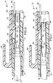
- Figure 2 shows the TPA device selectively engaged with connector housing 20, inserted into cavity 18 and located in a preloaded position of the TPA device. Terminal 14 is shown being initially inserted into passage 16 of the TPA device.
- Figure 3 shows terminal 14 having been inserted further in the direction of arrow "C” to a point whereat the mating end 56 of the terminal has biased flexible locking arm 50 upwardly in the direction of arrow "D".
- the arm is flexed upwardly by the mating end of the terminal engaging chamfered surface 54 of the locking arm. It should be noted that there is adequate space within cavity 18 for the locking arm of the TPA device to fully flex while the device is in its preloaded position.
- Figure 4 shows terminal 14 having been inserted further in the direction of arrow "E" whereat the mating end 56 of the terminal now has engaged primary locking arm 30 and has flexed the locking arm upwardly in the direction of arrow "F".
- the arm is flexed upwardly by engagement of the mating end of the terminal with chamfered surface 34 of the primary locking arm.
- locking arm 50 of TPA device 12 has not dropped into forward locking aperture 62 of the terminal, because, as stated above, the distal end of the locking arm is wider than the smaller aperture and simply will ride over the aperture along the top surface of the terminal.
- FIG. 5 shows terminal 14 having been inserted still further in the direction of arrow "G" but not yet to its fully inserted position.
- TPA device 12 still is in its preloaded position, and primary locking arm 30 of connector 10 and locking arm 50 of the TPA device still are in their flexed positions.
- FIG. 6 now shows terminal 14 having been inserted to its fully inserted position.
- Primary locking arm 30 now has returned or “snapped” back downwardly such that locking shoulder 32 now has interengaged into locking condition within forward locking aperture 62 of the terminal.
- the TPA device still is in its preloaded position.
- FIG 7 is similar to Figure 6 in that the terminal is in its fully inserted position in locking engagement with primary locking arm 30.
- TPA device 12 now has been moved in the direction of arrow "H" to its fully loaded and locking position.
- locking arm 50 of the TPA device has returned or "snapped” back to its unflexed condition, and abutment shoulder 52 is in locking position within rear aperture 64 of the terminal.
- the distal end of locking arm 50 engages angled surface 38 of camming boss 36, and the angled surface facilitates biasing abutment shoulder 52 into aperture 64 of the terminal.
- camming boss 36 provides a backing for locking arm 50.
- FIG 8 shows a condition wherein terminal 14 has been inserted into an incomplete position of insertion.
- TPA devices of the prior art such an incompletely inserted terminal would require a technician to search to find which terminal or terminals is incompletely inserted. Such a process wastes considerable time and money in the assembly operation of the connector.
- TPA device 12 of the invention being in its preloaded position, it can be seen that abutment shoulder 52 on the distal end of locking arm 50 has entered rear aperture 64 of the terminal.
- the TPA device upon movement of the TPA device in the direction of arrow "I", the combination of the TPA device along with the terminal (the abutment shoulders 52 on the flexible locking arm 50 engages an edge of the terminal aperture 64) will move in the direction of arrow "J" until the terminal reaches its fully inserted position as shown in Figure 7. Therefore, the TPA device is effective to "correct” situations of incompletely inserted terminals by moving the terminals with the TPA device from its preloaded position to its loaded position (i.e. from the position of Figure 8 to the position of Figure 7).
- Figure 8 shows just one incomplete position of insertion of terminal 14 whereupon TPA device 12 is effective to fully insert the terminal when the TPA device is moved from its preloaded position to its loaded position.
- Other incomplete positions of insertion of the terminal can range from the position shown in Figure 8 all the way to the position of the terminal shown in Figure 6. In any position therebetween, movement of the TPA device forwardly will cause abutment shoulder 52 to engage within rear locking aperture 64 of the terminal and move the terminal forwardly with the TPA device.
- Figure 9 shows a position of terminal 14 wherein the terminal is so incompletely inserted (i.e. too far to the rear) that TPA device 12 would be ineffective.
- the terminal is so far to the rear that the forward distal end of locking arm 50 simply will abut against angled surface 38 of camming boss 16 and jam between the surface and top wall of the terminal.
- Figures 10-13 show a procedure for selectively withdrawing one or more of terminals 14 from connector 10.
- Figure 10 shows that TPA device 12 has been moved back rearwardly in the direction of arrow "K" to its preloaded position.
- chamfered surface 54 on the underside of locking arm 50 simply will ride upwardly and over the rear edge of locking aperture 64 as the TPA device is moved back to its preloaded position.
- a probe-like tool 80 then can be inserted into cavity 18 into engagement with a rear chamfered surface 82 of primary locking arm 30 to lift locking shoulder 52 of the arm out of locking aperture 62 of the terminal as seen in Figure 11.
- the terminal then can be moved away from its fully inserted position in the direction of arrow "L” out of locking condition with the primary locking arm, as is seen in Figure 11.
- Figure 12 shows that a second probe 84 then can be inserted into passage 16 and into engagement with angled surface 54 on the underside of TPA locking arm 50 to lift the arm out of locking engagement with the terminal, as shown.
- the terminal now is free to be fully withdrawn in the direction of arrow "M" in Figure 13.
Landscapes
- Connector Housings Or Holding Contact Members (AREA)
- Details Of Connecting Devices For Male And Female Coupling (AREA)
Abstract
Description
- This invention generally relates to the art of electrical connectors and, particularly, to an electrical connector which incorporates an improved position assurance device that not only detects an incompletely inserted terminal but moves the incompletely inserted terminal to its fully inserted position.
- Generally, an electrical connector includes a dielectric housing mounting at least one electrically conductive terminal therein. The terminal is electrically connected to another circuit component, such as a discrete wire. Connectors often are employed in mateable pairs such that each terminal and the housing of one connector are mateable with a corresponding terminal and the housing of another connector.
- The terminals of electrical connectors frequently are very small components, such as components that are stamped and/or formed from thin sheet metal material. A poor quality electrical connection may occur if one or more terminals are not properly seated in its respective housing. The improper seating of a terminal in a housing may occur if the terminal is not fully inserted into the housing during the initial assembly of the connector or if the terminal is vibrated or pulled out of its fully seated condition during use of the connector. Failures of this type are a particular concern in the automotive industry where electrical components are subjected to vibration almost continuously during normal usage and are subjected to direct force during some maintenance. To avoid these problems, the automotive industry often requires connectors to be provided with some form of a terminal position assurance (TPA) system to detect incomplete insertion of the terminals. The automotive industry also generally requires locking means for locking the terminals in the housing, and a TPA system or device also performs this function.
- In using a typical TPA device, if the device detects that one or more terminals are not fully seated, a search is required to locate the incompletely inserted terminal(s). This can be a time consuming operation and adds to the cost of the connector assembly operation. The present invention is directed to solving this problem by providing a TPA device which not only detects an incompletely inserted terminal, but the device, itself, is used to move the incompletely inserted terminal to its fully inserted position.
- An object, therefore, of the invention is to provide an electrical connector with a new and improved terminal position assurance (TPA) device that not only detects whether or not a terminal is fully inserted and not only locks a terminal in its fully inserted position but facilitates moving an incompletely inserted terminal to its fully inserted position.
- In the exemplary embodiment of the invention, the connector includes a housing having a forward mating end and a rearward terminating end and at least one terminal-receiving cavity extending in a direction between the ends. A terminal is insertable into the cavity from the rearward terminating end of the housing. A TPA device is selectively engageable with the housing at the mating end thereof, with a terminal retention portion of the device insertable into the cavity in locking engagement with the terminal. Complementary interengaging abutment means are provided between the terminal and the TPA device for moving the terminal from at least one incomplete position of insertion to a fully inserted position in response to engaging the TPA device with the housing and fully inserting the terminal portion into the cavity.
- As disclosed herein, the retention portion of the TPA device is provided by a flexible locking arm having an abutment shoulder for engaging the terminal. The abutment shoulder, in turn, forms part of the complementary interengaging abutment means which also includes an aperture in the terminal engageable by the abutment shoulder.
- The connector further includes a primary locking means in the form of a second flexible locking arm inside the cavity. The second arm includes a locking shoulder for locking engagement with another aperture in the terminal when in its fully inserted position.
- In the preferred embodiment of the invention, the TPA device is selectively engageable with the housing in two positions, preloaded and fully loaded. When the TPA device is in its preloaded position, the terminal can be inserted into the cavity. When the TPA device is in its fully loaded position, the retention portion locks the terminal in its fully inserted position. When the TPA device is moved from the preloaded position to the fully loaded position, the complementary interengaging abutment means engage the terminal if in its incomplete position of insertion and moves the terminal to its fully inserted position.
- Other objects, features and advantages of the invention will be apparent from the following detailed description taken in connection with the accompanying drawings.
- The features of this invention which are believed to be novel are set forth with particularity in the appended claims. The invention, together with its objects and the advantages thereof, may be best understood by reference to the following description taken in conjunction with the accompanying drawings, in which like reference numerals identify like elements in the figures and in which:
- FIGURE 1 is an exploded perspective view of an electrical connector assembly, including a TPA device, embodying the concepts of the invention;
- FIGURE 2 is a vertical section taken generally along line 2-2 of Figure 1, but with the TPA device assembled to the connector in its preloaded position and with the terminal just partially inserted;
- FIGURE 3 is a view similar to that of Figure 2, but with the terminal inserted further such that the mating end thereof is in engagement with and deflecting the locking arm of the TPA device;
- FIGURE 4 is a view similar to that of Figure 3, but with the terminal inserted further to a position of engagement with the primary locking arm of the connector;
- FIGURE 5 is a view similar to that of Figure 4, but with the terminal inserted further to a position wherein both apertures in the terminal have passed the locking arm of the TPA device;
- FIGURE 6 is a view similar to that of Figure 5, but with the terminal in its fully inserted position in engagement with the primary locking arm of the connector;
- FIGURE 7 is a view similar to that of Figure 6, but with the TPA device moved to its fully loaded position;
- FIGURE 8 is a view similar to that of Figures 2-7, but with the TPA device engaging an incompletely inserted terminal;
- FIGURE 9 is a view similar to that of Figures 1-8, but showing a terminal in an inadequately inserted position;
- FIGURE 10 is a view similar to that of Figures 2-9, but with the TPA device withdrawn back to its preloaded position and a probe is inserted for releasing the primary locking arm;
- FIGURE 11 is a view similar to that of Figure 10 with the probe inserted further to release the primary locking arm and the terminal withdrawn from its fully inserted position;
- FIGURE 12 is a view similar to that of Figure 11, but with a second probe inserted for releasing the TPA locking arm; and
- FIGURE 13 is a view similar to that of Figure 12, but showing the terminal being fully withdrawn.
- Referring to the drawings in greater detail, and first to Figures 1 and 2, the invention is embodied in an electrical connector, generally designated 10, which includes a TPA device, generally designated 12, selectively engageable with the connector. A plurality of terminals, generally designated 14, are inserted through
passages 16 in the TPA device and into a terminal-receivingcavity 18 of the connector. Only one terminal is shown in the drawings to avoid cluttering a clear depiction of the invention. As will be understood hereinafter,TPA device 12 is adapted for insertion into terminal-receiving cavity 18 ofconnector 10, andterminals 14 then are inserted intopassages 16 of the TPA device and further intocavity 18 of the connector. - More particularly,
connector 10 includes ahousing 20 having aforward mating end 22 and a rearward terminatingend 24. The housing is unitarily molded of dielectric material, such as plastic or the like, andcavity 18 extends betweenmating end 22 and terminatingend 24 of the housing. Although not forming part of the invention,connector housing 20 also includesintegral side flanges 26 to facilitate mounting the connector in a panel, and latch means 28 for latching the connector to a complementary mating connector or other connecting device. - As seen best in Figure 2,
connector housing 20 has a primary locking means withincavity 18, in the form of aflexible locking arm 30 having a forwardly facing locking shoulder orhook 32. The distal end of the locking arm is chamfered, as at 34, to present a rearwardly facing angled surface toterminal 14 oblique to an insertion direction "A" of the terminal. Acamming boss 36 also is formed integral withconnector housing 20 withincavity 18. The camming boss also forms a rearwardly facingangled surface 38 extending oblique to insertion direction "A". - Referring back to Figure 1,
TPA device 12 includesrear walls 40 andfront partitions 42 for separating terminal-receivingpassages 16. It can be seen that there are two rows of passages divided transversely of the TPA device by acentral wall 44. Cantileveredlatch arms 46 are provided at opposite sides of the TPA device for gripping and squeezing by a technician to facilitate inserting the TPA device intocavity 18 ofconnector housing 20 in the direction of arrow "B". Latch means, generally designated 48, are provided, operatively associated withlatch arms 46, for latching the TPA device within the cavity in cooperation with complementary latching means (not shown) therewithin. - Referring to Figure 2 in conjunction with Figure 1,
TPA device 12 includes aflexible locking arm 50 located within and projecting forwardly of each terminal-receivingpassage 16. The locking arm has a forwardly facingabutment shoulder 52 on the distal end thereof. Achamfered surface 54 faces rearwardly behind the distal end of the locking arm at an angle to insertion direction "A" of the terminal. -
Terminal 14 has aforward mating end 56 and a rearward terminatingend 58. The forward mating end is generally box-shaped for defining a receptacle to receive a mating male terminal of the complementary connecting device. Terminatingend 58 is adapted for crimping onto an electrical wire orcable 60. The terminal includes aforward locking aperture 62 adapted for locking engagement withprimary locking arm 30 withincavity 18 ofconnector housing 20. The terminal includes a second orrear locking aperture 64 for locking engagement with lockingarm 50 ofTPA device 12 withinpassage 16 of the device. It should be observed in Figure 1 that forward lockingaperture 62 is smaller in a transverse direction thanrear locking aperture 64. To that end, the distal end of lockingarm 50 of the TPA device (i.e. at lockingshoulder 52 and chamfered surface 54) is wider than forward lockingaperture 62 so that the locking arm of the TPA device simply will ride over the top surface of the terminal past forward lockingaperture 62. In turn, the forward locking aperture is sized for receiving the forward hooked end ofprimary locking arm 30. - In operation of the invention, including
connector 10,TPA device 12 and terminal(s) 14, Figure 2 shows the TPA device selectively engaged withconnector housing 20, inserted intocavity 18 and located in a preloaded position of the TPA device.Terminal 14 is shown being initially inserted intopassage 16 of the TPA device. - Figure 3 shows terminal 14 having been inserted further in the direction of arrow "C" to a point whereat the
mating end 56 of the terminal has biasedflexible locking arm 50 upwardly in the direction of arrow "D". The arm is flexed upwardly by the mating end of the terminal engaging chamferedsurface 54 of the locking arm. It should be noted that there is adequate space withincavity 18 for the locking arm of the TPA device to fully flex while the device is in its preloaded position. - Figure 4 shows terminal 14 having been inserted further in the direction of arrow "E" whereat the
mating end 56 of the terminal now has engagedprimary locking arm 30 and has flexed the locking arm upwardly in the direction of arrow "F". The arm is flexed upwardly by engagement of the mating end of the terminal withchamfered surface 34 of the primary locking arm. It also can be seen in Figure 4 that lockingarm 50 ofTPA device 12 has not dropped into forward lockingaperture 62 of the terminal, because, as stated above, the distal end of the locking arm is wider than the smaller aperture and simply will ride over the aperture along the top surface of the terminal. - Figure 5 shows terminal 14 having been inserted still further in the direction of arrow "G" but not yet to its fully inserted position.
TPA device 12 still is in its preloaded position, andprimary locking arm 30 ofconnector 10 and lockingarm 50 of the TPA device still are in their flexed positions. - Figure 6 now shows terminal 14 having been inserted to its fully inserted position.
Primary locking arm 30 now has returned or "snapped" back downwardly such that lockingshoulder 32 now has interengaged into locking condition within forward lockingaperture 62 of the terminal. The TPA device still is in its preloaded position. - Figure 7 is similar to Figure 6 in that the terminal is in its fully inserted position in locking engagement with
primary locking arm 30. However,TPA device 12 now has been moved in the direction of arrow "H" to its fully loaded and locking position. It can be seen that lockingarm 50 of the TPA device has returned or "snapped" back to its unflexed condition, andabutment shoulder 52 is in locking position withinrear aperture 64 of the terminal. During movement of the TPA device from its preloaded position (Figs. 2-6) to its loaded and locking position (Fig. 7), the distal end of lockingarm 50 engages angledsurface 38 ofcamming boss 36, and the angled surface facilitates biasingabutment shoulder 52 intoaperture 64 of the terminal. In the fully loaded position of the TPA device as shown in Figure 7, it can be seen thatcamming boss 36 provides a backing for lockingarm 50. - Figure 8 shows a condition wherein terminal 14 has been inserted into an incomplete position of insertion. With TPA devices of the prior art, such an incompletely inserted terminal would require a technician to search to find which terminal or terminals is incompletely inserted. Such a process wastes considerable time and money in the assembly operation of the connector. However, with
TPA device 12 of the invention being in its preloaded position, it can be seen thatabutment shoulder 52 on the distal end of lockingarm 50 has enteredrear aperture 64 of the terminal. Now, upon movement of the TPA device in the direction of arrow "I", the combination of the TPA device along with the terminal (the abutment shoulders 52 on theflexible locking arm 50 engages an edge of the terminal aperture 64) will move in the direction of arrow "J" until the terminal reaches its fully inserted position as shown in Figure 7. Therefore, the TPA device is effective to "correct" situations of incompletely inserted terminals by moving the terminals with the TPA device from its preloaded position to its loaded position (i.e. from the position of Figure 8 to the position of Figure 7). - Figure 8 shows just one incomplete position of insertion of
terminal 14 whereuponTPA device 12 is effective to fully insert the terminal when the TPA device is moved from its preloaded position to its loaded position. Other incomplete positions of insertion of the terminal can range from the position shown in Figure 8 all the way to the position of the terminal shown in Figure 6. In any position therebetween, movement of the TPA device forwardly will causeabutment shoulder 52 to engage withinrear locking aperture 64 of the terminal and move the terminal forwardly with the TPA device. - On the other hand, Figure 9 shows a position of
terminal 14 wherein the terminal is so incompletely inserted (i.e. too far to the rear) thatTPA device 12 would be ineffective. In other words, it can be seen in Figure 9 that the terminal is so far to the rear that the forward distal end of lockingarm 50 simply will abut against angledsurface 38 ofcamming boss 16 and jam between the surface and top wall of the terminal. - Lastly, Figures 10-13 show a procedure for selectively withdrawing one or more of
terminals 14 fromconnector 10. In particularly, Figure 10 shows thatTPA device 12 has been moved back rearwardly in the direction of arrow "K" to its preloaded position. During this movement, chamferedsurface 54 on the underside of lockingarm 50 simply will ride upwardly and over the rear edge of lockingaperture 64 as the TPA device is moved back to its preloaded position. A probe-like tool 80 then can be inserted intocavity 18 into engagement with a rear chamferedsurface 82 ofprimary locking arm 30 to lift lockingshoulder 52 of the arm out of lockingaperture 62 of the terminal as seen in Figure 11. The terminal then can be moved away from its fully inserted position in the direction of arrow "L" out of locking condition with the primary locking arm, as is seen in Figure 11. - Figure 12 shows that a
second probe 84 then can be inserted intopassage 16 and into engagement with angledsurface 54 on the underside ofTPA locking arm 50 to lift the arm out of locking engagement with the terminal, as shown. The terminal now is free to be fully withdrawn in the direction of arrow "M" in Figure 13. - It will be understood that the invention may be embodied in other specific forms without departing from the spirit or central characteristics thereof. The present examples and embodiments, therefore, are to be considered in all respects as illustrative and not restrictive, and the invention is not to be limited to the details given herein.
Claims (13)
- An electrical connector (10), comprising:
a housing (20) having a forward mating end and a rearward terminating end (24) and at least one terminal-receiving cavity extending (18) in a direction between the ends;
a terminal (14) insertable into the cavity (18) from the rearward terminating end of the housing;
a TPA device (12) selectively engageable with the housing (20) at said terminating end (24) thereof with a terminal retention portion (50) insertable into the cavity in locking engagement with the terminal; and
complementary interengaging abutment means (52,64) between the terminal (14) and the TPA device (12) for moving the terminal from at least one incomplete position of insertion to a fully inserted position in response to engaging the TPA device with the housing (20) and fully inserting the terminal retention portion into the cavity. - The electrical connector of claim 1 wherein said complementary interengaging abutment means include an abutment portion (52) on the retention portion (50) of the TPA device (12).
- The electrical connector of claim 2 wherein said abutment portion (50) of the TPA device (12) includes an abutment shoulder (52) for engaging the terminal, the abutment shoulder, in turn, comprising part of said complementary interengaging abutment means (52,64).
- The electrical connector of claim 3 wherein said retention portion (50) of the TPA device (12) comprises a flexible locking arm (30) having said abutment shoulder (52) thereon.
- The electrical connector of claim 4 wherein said complementary interengaging abutment means (52,64) include an aperture (64) in the terminal (14) engageable by said abutment shoulder (52).
- The electrical connector of claim 1, including a primary locking means (30) on the housing (20) engageable with the terminal (10) for locking the terminal in its fully inserted position.
- The electrical connector of claim 6 wherein said primary locking means comprise a flexible locking arm (30) inside the cavity (18) and including a locking shoulder (32) for locking engagement within an aperture (62) in the terminal (14) when in its fully inserted position.
- The electrical connector of claim 1 wherein said TPA device (12) is selectively engageable with the housing (20) in two positions, preloaded and fully loaded, wherein when the TPA device (12) is preloaded the terminal can be inserted into the cavity (18), when the TPA device (12) is fully loaded the retention portion (50) locks the terminal (14) in its fully inserted position, and when the TPA device (12) is moved from the preloaded position to the fully loaded position the complementary interengaging abutment means (52,64) engage the terminal (14) if in its incomplete position of insertion and moves the terminal to its fully inserted position.
- The electrical connector of claim 1 wherein said TPA device (12) includes a terminal-receiving passage (16) aligned with the terminal-receiving cavity (18) of the housing (20).
- An electrical connector (10), comprising:
a housing (20) having a forward mating end (22) and a rearward terminating end (24) and at least one terminal-receiving cavity (18) extending in a direction between the ends;
a terminal (14) insertable into the cavity (18) from the rearward terminating end (24) of the housing (20), the terminal including an abutment means (64) thereon;
a TPA device (12) selectively engageable with the housing (20) at said terminating end (24) thereof and including an abutment shoulder (52) for engaging the abutment means (64) of the terminal whereby the TPA device moves the terminal from at least one incomplete position of insertion to a fully inserted position in response to engaging the TPA device (12) with the housing (20); and
said TPA device (12) is selectively engageable with the housing (20) in two positions, preloaded and fully loaded, wherein when the TPA device (12) is preloaded the terminal (14) can be inserted into the cavity (18), when the TPA device (12) is fully loaded the abutment shoulder (52) locks the terminal (14) in its fully inserted position, and when the TPA device (12) is moved from the preloaded position to the fully loaded position the abutment shoulder (52) engages the abutment means (64) of the terminal (14) if in its incomplete position of insertion and moves the terminal to its fully inserted position. - The electrical connector of claim 10 wherein said TPA device includes a flexible locking arm (30) having said abutment shoulder (52) thereon.
- The electrical connector of claim 11, including a flexible primary locking arm (30) inside the cavity (18) and including a locking shoulder (32) for locking engagement within an aperture (62) in the terminal (14) when in its fully inserted position.
- The electrical connector of claim 10, including a primary locking means (30) on the housing (20) engageable with the terminal (14) for locking the terminal in its fully inserted position.
Applications Claiming Priority (2)
| Application Number | Priority Date | Filing Date | Title |
|---|---|---|---|
| US314981 | 1994-09-29 | ||
| US08/314,981 US5522740A (en) | 1994-09-29 | 1994-09-29 | Electrical connector with terminal position assurance device that facilitates fully inserting a terminal |
Publications (3)
| Publication Number | Publication Date |
|---|---|
| EP0704934A2 true EP0704934A2 (en) | 1996-04-03 |
| EP0704934A3 EP0704934A3 (en) | 1996-08-28 |
| EP0704934B1 EP0704934B1 (en) | 2001-07-04 |
Family
ID=23222338
Family Applications (1)
| Application Number | Title | Priority Date | Filing Date |
|---|---|---|---|
| EP95114422A Expired - Lifetime EP0704934B1 (en) | 1994-09-29 | 1995-09-14 | Electrical connector with terminal position assurance device that facilitates fully inserting a terminal |
Country Status (6)
| Country | Link |
|---|---|
| US (1) | US5522740A (en) |
| EP (1) | EP0704934B1 (en) |
| JP (1) | JP2934821B2 (en) |
| KR (1) | KR100216002B1 (en) |
| DE (1) | DE69521580T2 (en) |
| TW (1) | TW405766U (en) |
Cited By (10)
| Publication number | Priority date | Publication date | Assignee | Title |
|---|---|---|---|---|
| ES2124662A1 (en) * | 1996-08-28 | 1999-02-01 | Mecanismos Aux Ind | A retention system for terminals |
| WO2010046293A1 (en) * | 2008-10-24 | 2010-04-29 | Weidmüller Interface GmbH & Co. KG | Plug connection with a plug part and a socket part, and adapter housing for accommodating the plug connection |
| CN109196729A (en) * | 2016-06-15 | 2019-01-11 | 株式会社自动网络技术研究所 | Connector |
| WO2020172390A1 (en) * | 2019-02-20 | 2020-08-27 | Ran Roland Kohen | Quick connect device with transverse release |
| US10845046B2 (en) | 2017-05-01 | 2020-11-24 | Ran Roland Kohen | Connecting lighting to poles without tools |
| US11025023B2 (en) | 2015-05-12 | 2021-06-01 | Ran Roland Kohen | Smart quick connect device for electrical fixtures |
| US11133632B2 (en) | 2017-03-10 | 2021-09-28 | Ran Roland Kohen | Quick connect device for recessed electrical fixtures |
| US11196216B2 (en) | 2017-04-17 | 2021-12-07 | Ran Roland Kohen | Disconnecting and supporting quick release electrical fixtures |
| US11215188B2 (en) | 2014-09-30 | 2022-01-04 | Sql Technologies Corp. | Apparatus including a combination of a ceiling fan and a heater with light effects |
| US11460184B2 (en) | 2017-03-05 | 2022-10-04 | Skyx Platforms Corp. | Modular smart quick connect device for electrical fixtures |
Families Citing this family (26)
| Publication number | Priority date | Publication date | Assignee | Title |
|---|---|---|---|---|
| DE4433617C2 (en) * | 1994-09-21 | 1997-04-24 | Kostal Leopold Gmbh & Co Kg | Electrical connector part |
| JP3046738B2 (en) * | 1995-01-25 | 2000-05-29 | 矢崎総業株式会社 | Electrical junction box |
| FR2746968B1 (en) * | 1996-03-29 | 1998-06-12 | Framatome Connectors France | CONNECTION MODULE WITH REMOVABLE CONTACTS AND CONNECTION BLOCK USING THE SAME |
| US5716234A (en) * | 1996-10-03 | 1998-02-10 | General Motors Corporation | Electrical connector with positive lock retention |
| US5779501A (en) * | 1996-10-11 | 1998-07-14 | Ut Automotive Dearborn, Inc. | Connector |
| US6045404A (en) * | 1997-06-30 | 2000-04-04 | The Whitaker Corporation | Electrical connector having a terminal position assurance device |
| FR2774816B1 (en) * | 1998-02-11 | 2004-02-20 | Cinch Connecteurs Sa | ELECTRICAL CONNECTOR HOUSING ELEMENT |
| US6027377A (en) * | 1998-06-04 | 2000-02-22 | Wang; Jen-Ching | Plug terminal mounting arrangement of an electric plug for a trailer |
| US6234826B1 (en) | 1999-04-30 | 2001-05-22 | Cardell Corporation | Connector position assurance device |
| US6290539B1 (en) | 1999-04-30 | 2001-09-18 | Cardell Corporation | Electrical connector having a two-piece socket portion |
| US6533611B2 (en) * | 2000-10-03 | 2003-03-18 | Delphi Technologies, Inc. | Electrical connector assembly with secondary terminal lock |
| US6935893B1 (en) * | 2004-02-11 | 2005-08-30 | Molex Incorporated | Electrical connector with terminal position assurance device |
| US7048583B1 (en) * | 2005-04-25 | 2006-05-23 | J.S.T. Corporation | Electrical connector with a terminal position assurance mechanism |
| US7179135B2 (en) * | 2005-04-25 | 2007-02-20 | J.S. T. Corporation | Electrical connector with a terminal position assurance mechanism |
| CN2862397Y (en) * | 2005-12-27 | 2007-01-24 | 富士康(昆山)电脑接插件有限公司 | Electric connector assembly |
| US7582857B2 (en) * | 2006-04-18 | 2009-09-01 | The Trustees Of The University Of Pennsylvania | Sensor and polarimetric filters for real-time extraction of polarimetric information at the focal plane |
| US7347743B2 (en) * | 2006-04-19 | 2008-03-25 | Delphi Technologies, Inc. | Stagable electrical connector and method of assembly |
| JP4720605B2 (en) * | 2006-04-27 | 2011-07-13 | 富士ゼロックス株式会社 | Electronics |
| CN200972950Y (en) * | 2006-10-09 | 2007-11-07 | 富士康(昆山)电脑接插件有限公司 | Electric connector |
| JP6340411B2 (en) | 2013-03-29 | 2018-06-06 | モレックス エルエルシー | Connector with TPA |
| US9912092B2 (en) * | 2016-01-29 | 2018-03-06 | Te Connectivity Corporation | Ergonomic terminal position assurance member |
| JP6475669B2 (en) * | 2016-07-13 | 2019-02-27 | 矢崎総業株式会社 | connector |
| CN209233038U (en) * | 2018-11-23 | 2019-08-09 | 泰科电子(上海)有限公司 | Terminal retainer and to matching terminal retainer |
| CN110048259B (en) * | 2019-05-24 | 2024-04-19 | 深圳市兴万联电子有限公司 | Electric connector |
| US10811804B1 (en) * | 2019-07-10 | 2020-10-20 | Lear Corporation | Electric terminal connector assembly with a terminal lock |
| JP7375840B2 (en) * | 2022-02-03 | 2023-11-08 | Smk株式会社 | electrical connectors |
Family Cites Families (5)
| Publication number | Priority date | Publication date | Assignee | Title |
|---|---|---|---|---|
| US4955827A (en) * | 1989-09-14 | 1990-09-11 | United Technologies Automotive, Inc. | Double-locked subminiature terminal pin with opposed locking openings |
| US4944688A (en) * | 1989-09-25 | 1990-07-31 | Amp Incorporated | Programmable sealed connector |
| JPH0495369A (en) * | 1990-08-01 | 1992-03-27 | Yazaki Corp | Electrical connector with terminal fixture |
| JP2573752B2 (en) * | 1991-03-20 | 1997-01-22 | 矢崎総業株式会社 | Connector with terminal retainer |
| JP2505389Y2 (en) * | 1991-03-26 | 1996-07-31 | 矢崎総業株式会社 | Connector with terminal locking device |
-
1994
- 1994-09-29 US US08/314,981 patent/US5522740A/en not_active Expired - Lifetime
-
1995
- 1995-09-14 DE DE69521580T patent/DE69521580T2/en not_active Expired - Fee Related
- 1995-09-14 EP EP95114422A patent/EP0704934B1/en not_active Expired - Lifetime
- 1995-09-20 JP JP7266370A patent/JP2934821B2/en not_active Expired - Fee Related
- 1995-09-27 KR KR1019950032073A patent/KR100216002B1/en not_active IP Right Cessation
-
1996
- 1996-10-09 TW TW087211421U patent/TW405766U/en not_active IP Right Cessation
Non-Patent Citations (1)
| Title |
|---|
| None |
Cited By (12)
| Publication number | Priority date | Publication date | Assignee | Title |
|---|---|---|---|---|
| ES2124662A1 (en) * | 1996-08-28 | 1999-02-01 | Mecanismos Aux Ind | A retention system for terminals |
| WO2010046293A1 (en) * | 2008-10-24 | 2010-04-29 | Weidmüller Interface GmbH & Co. KG | Plug connection with a plug part and a socket part, and adapter housing for accommodating the plug connection |
| RU2526853C2 (en) * | 2008-10-24 | 2014-08-27 | Вайдмюллер Интерфейс Гмбх Унд Ко. Кг | Plug and socket joint with plug and socket connectors and adapter for their embedding |
| US11215188B2 (en) | 2014-09-30 | 2022-01-04 | Sql Technologies Corp. | Apparatus including a combination of a ceiling fan and a heater with light effects |
| US11025023B2 (en) | 2015-05-12 | 2021-06-01 | Ran Roland Kohen | Smart quick connect device for electrical fixtures |
| CN109196729A (en) * | 2016-06-15 | 2019-01-11 | 株式会社自动网络技术研究所 | Connector |
| US11460184B2 (en) | 2017-03-05 | 2022-10-04 | Skyx Platforms Corp. | Modular smart quick connect device for electrical fixtures |
| US11133632B2 (en) | 2017-03-10 | 2021-09-28 | Ran Roland Kohen | Quick connect device for recessed electrical fixtures |
| US11196216B2 (en) | 2017-04-17 | 2021-12-07 | Ran Roland Kohen | Disconnecting and supporting quick release electrical fixtures |
| US10845046B2 (en) | 2017-05-01 | 2020-11-24 | Ran Roland Kohen | Connecting lighting to poles without tools |
| WO2020172390A1 (en) * | 2019-02-20 | 2020-08-27 | Ran Roland Kohen | Quick connect device with transverse release |
| US11916333B2 (en) | 2019-02-20 | 2024-02-27 | Skyx Platforms Corp. | Quick connect device with transverse release |
Also Published As
| Publication number | Publication date |
|---|---|
| EP0704934A3 (en) | 1996-08-28 |
| JP2934821B2 (en) | 1999-08-16 |
| EP0704934B1 (en) | 2001-07-04 |
| US5522740A (en) | 1996-06-04 |
| KR960012622A (en) | 1996-04-20 |
| DE69521580T2 (en) | 2002-06-06 |
| TW405766U (en) | 2000-09-11 |
| JPH08106953A (en) | 1996-04-23 |
| DE69521580D1 (en) | 2001-08-09 |
| KR100216002B1 (en) | 1999-08-16 |
Similar Documents
| Publication | Publication Date | Title |
|---|---|---|
| US5522740A (en) | Electrical connector with terminal position assurance device that facilitates fully inserting a terminal | |
| US5622521A (en) | Electrical connector with terminal position assurance device that facilitates fully inserting a terminal | |
| US5252096A (en) | Connector | |
| EP0923164B1 (en) | Electrical connector assembly with terminal retainer system | |
| US6386898B1 (en) | Connector fitting construction | |
| EP0706237B1 (en) | Electrical connector with terminal position assurance device and guide means for a mating connector | |
| EP0952634A2 (en) | Electrical connector position assurance system | |
| EP0881711A1 (en) | Electrical connector system for a flat flexible circuit | |
| US5910028A (en) | Connector | |
| EP0678938A1 (en) | Connector | |
| EP0644617A1 (en) | Connector with terminal locking spacer | |
| EP1570548B1 (en) | Electrical connector with terminal position assurance system | |
| US5890935A (en) | Electrical connector with terminal position assurance device | |
| US5647772A (en) | Terminal position assurance system for an electrical connector | |
| US5599200A (en) | Connector with a terminal protecting board | |
| US6019645A (en) | Electrical connector assembly with terminal position assurance device | |
| EP0573931B1 (en) | Lockable electrical connector assembly | |
| EP0244192B1 (en) | Electrical connector | |
| US5630733A (en) | Female terminal | |
| US4647128A (en) | Electrical connector system with releasable latching | |
| US6325663B1 (en) | Half-fitting prevention connector | |
| US6478632B2 (en) | Shake preventing construction for a terminal fitting and a connector | |
| US4824404A (en) | Secondary terminal lock | |
| EP0821836B1 (en) | Temporary terminal retention feature |
Legal Events
| Date | Code | Title | Description |
|---|---|---|---|
| PUAI | Public reference made under article 153(3) epc to a published international application that has entered the european phase |
Free format text: ORIGINAL CODE: 0009012 |
|
| AK | Designated contracting states |
Kind code of ref document: A2 Designated state(s): DE FR GB IT |
|
| PUAL | Search report despatched |
Free format text: ORIGINAL CODE: 0009013 |
|
| AK | Designated contracting states |
Kind code of ref document: A3 Designated state(s): DE FR GB IT |
|
| 17P | Request for examination filed |
Effective date: 19970123 |
|
| 17Q | First examination report despatched |
Effective date: 19980914 |
|
| GRAG | Despatch of communication of intention to grant |
Free format text: ORIGINAL CODE: EPIDOS AGRA |
|
| GRAG | Despatch of communication of intention to grant |
Free format text: ORIGINAL CODE: EPIDOS AGRA |
|
| GRAH | Despatch of communication of intention to grant a patent |
Free format text: ORIGINAL CODE: EPIDOS IGRA |
|
| ITF | It: translation for a ep patent filed | ||
| GRAH | Despatch of communication of intention to grant a patent |
Free format text: ORIGINAL CODE: EPIDOS IGRA |
|
| GRAA | (expected) grant |
Free format text: ORIGINAL CODE: 0009210 |
|
| AK | Designated contracting states |
Kind code of ref document: B1 Designated state(s): DE FR GB IT |
|
| REF | Corresponds to: |
Ref document number: 69521580 Country of ref document: DE Date of ref document: 20010809 |
|
| ET | Fr: translation filed | ||
| REG | Reference to a national code |
Ref country code: GB Ref legal event code: IF02 |
|
| PLBE | No opposition filed within time limit |
Free format text: ORIGINAL CODE: 0009261 |
|
| STAA | Information on the status of an ep patent application or granted ep patent |
Free format text: STATUS: NO OPPOSITION FILED WITHIN TIME LIMIT |
|
| 26N | No opposition filed | ||
| PGFP | Annual fee paid to national office [announced via postgrant information from national office to epo] |
Ref country code: GB Payment date: 20030807 Year of fee payment: 9 |
|
| PG25 | Lapsed in a contracting state [announced via postgrant information from national office to epo] |
Ref country code: GB Free format text: LAPSE BECAUSE OF NON-PAYMENT OF DUE FEES Effective date: 20040914 |
|
| GBPC | Gb: european patent ceased through non-payment of renewal fee |
Effective date: 20040914 |
|
| PG25 | Lapsed in a contracting state [announced via postgrant information from national office to epo] |
Ref country code: IT Free format text: LAPSE BECAUSE OF NON-PAYMENT OF DUE FEES;WARNING: LAPSES OF ITALIAN PATENTS WITH EFFECTIVE DATE BEFORE 2007 MAY HAVE OCCURRED AT ANY TIME BEFORE 2007. THE CORRECT EFFECTIVE DATE MAY BE DIFFERENT FROM THE ONE RECORDED. Effective date: 20050914 |
|
| PGFP | Annual fee paid to national office [announced via postgrant information from national office to epo] |
Ref country code: FR Payment date: 20080917 Year of fee payment: 14 |
|
| PGFP | Annual fee paid to national office [announced via postgrant information from national office to epo] |
Ref country code: DE Payment date: 20081031 Year of fee payment: 14 |
|
| REG | Reference to a national code |
Ref country code: FR Ref legal event code: ST Effective date: 20100531 |
|
| PG25 | Lapsed in a contracting state [announced via postgrant information from national office to epo] |
Ref country code: FR Free format text: LAPSE BECAUSE OF NON-PAYMENT OF DUE FEES Effective date: 20090930 Ref country code: DE Free format text: LAPSE BECAUSE OF NON-PAYMENT OF DUE FEES Effective date: 20100401 |