EP0704271B1 - Surface preparation for thermal coatings - Google Patents
Surface preparation for thermal coatings Download PDFInfo
- Publication number
- EP0704271B1 EP0704271B1 EP95306162A EP95306162A EP0704271B1 EP 0704271 B1 EP0704271 B1 EP 0704271B1 EP 95306162 A EP95306162 A EP 95306162A EP 95306162 A EP95306162 A EP 95306162A EP 0704271 B1 EP0704271 B1 EP 0704271B1
- Authority
- EP
- European Patent Office
- Prior art keywords
- dielectric
- conductive surface
- gap
- spark
- voltage
- Prior art date
- Legal status (The legal status is an assumption and is not a legal conclusion. Google has not performed a legal analysis and makes no representation as to the accuracy of the status listed.)
- Expired - Lifetime
Links
Images

Classifications
-
- C—CHEMISTRY; METALLURGY
- C23—COATING METALLIC MATERIAL; COATING MATERIAL WITH METALLIC MATERIAL; CHEMICAL SURFACE TREATMENT; DIFFUSION TREATMENT OF METALLIC MATERIAL; COATING BY VACUUM EVAPORATION, BY SPUTTERING, BY ION IMPLANTATION OR BY CHEMICAL VAPOUR DEPOSITION, IN GENERAL; INHIBITING CORROSION OF METALLIC MATERIAL OR INCRUSTATION IN GENERAL
- C23C—COATING METALLIC MATERIAL; COATING MATERIAL WITH METALLIC MATERIAL; SURFACE TREATMENT OF METALLIC MATERIAL BY DIFFUSION INTO THE SURFACE, BY CHEMICAL CONVERSION OR SUBSTITUTION; COATING BY VACUUM EVAPORATION, BY SPUTTERING, BY ION IMPLANTATION OR BY CHEMICAL VAPOUR DEPOSITION, IN GENERAL
- C23C4/00—Coating by spraying the coating material in the molten state, e.g. by flame, plasma or electric discharge
- C23C4/02—Pretreatment of the material to be coated, e.g. for coating on selected surface areas
-
- B—PERFORMING OPERATIONS; TRANSPORTING
- B23—MACHINE TOOLS; METAL-WORKING NOT OTHERWISE PROVIDED FOR
- B23H—WORKING OF METAL BY THE ACTION OF A HIGH CONCENTRATION OF ELECTRIC CURRENT ON A WORKPIECE USING AN ELECTRODE WHICH TAKES THE PLACE OF A TOOL; SUCH WORKING COMBINED WITH OTHER FORMS OF WORKING OF METAL
- B23H1/00—Electrical discharge machining, i.e. removing metal with a series of rapidly recurring electrical discharges between an electrode and a workpiece in the presence of a fluid dielectric
- B23H1/08—Working media
-
- B—PERFORMING OPERATIONS; TRANSPORTING
- B23—MACHINE TOOLS; METAL-WORKING NOT OTHERWISE PROVIDED FOR
- B23H—WORKING OF METAL BY THE ACTION OF A HIGH CONCENTRATION OF ELECTRIC CURRENT ON A WORKPIECE USING AN ELECTRODE WHICH TAKES THE PLACE OF A TOOL; SUCH WORKING COMBINED WITH OTHER FORMS OF WORKING OF METAL
- B23H9/00—Machining specially adapted for treating particular metal objects or for obtaining special effects or results on metal objects
-
- B—PERFORMING OPERATIONS; TRANSPORTING
- B23—MACHINE TOOLS; METAL-WORKING NOT OTHERWISE PROVIDED FOR
- B23H—WORKING OF METAL BY THE ACTION OF A HIGH CONCENTRATION OF ELECTRIC CURRENT ON A WORKPIECE USING AN ELECTRODE WHICH TAKES THE PLACE OF A TOOL; SUCH WORKING COMBINED WITH OTHER FORMS OF WORKING OF METAL
- B23H9/00—Machining specially adapted for treating particular metal objects or for obtaining special effects or results on metal objects
- B23H9/008—Surface roughening or texturing
Definitions
- This invention relates to a method of preparing surfaces for receiving thermally sprayed coatings, and more particularly to the use of electrical discharge for roughening surfaces to promote a mechanical bond with such coatings.
- Grit blasting requires a high pressure flow of a fluid medium to carry the grit to the surface to be roughened.
- the flow must have a high pressure, usually greater than 0.1 MPa [15 psi]; it utilises a grit medium such as silica sand, aluminium oxide, chilled iron or garnet to produce a roughened surface.
- grit blasting the surface must be cleansed of the grit and dust before coating thereover.
- Grit blasting for high volume on-line manufacturing of thermal sprayed coated components is accompanied by the following concerns: grit contamination of the components and process equipment; difficulty of on-line collection and containment of the grit medium; grit blasting may not allow for highly accurate dimensional control; grit blasting is a line of sight process making surface preparation of complex components difficult; and sometimes reproducibility of surface roughness is difficult to achieve.
- Water jetting requires even higher pressures to impact the metal surface to dimple and abrade the surface. Such technique requires very high powered pumps, each of which are expensive and lack precise controllability of roughening.
- electrical discharge machining has been utilized to create smooth metal surfaces or to cut smoothly through metals. Electrical discharge machining has been known for close to 50 years.
- a workpiece usually the cathode
- a tool electrode
- Every discharge pulse is like a miniature lightening bolt that melts, vaporises and removes a minuscule portion of the workpiece without mechanical contact or stress supplied by the electrode on the workpiece.
- a dielectric liquid is used in the gap between the material to be eroded and the electrode. The liquid serves to carry away machined particles as the electrolyte flows through the gap.
- This invention in a first aspect, is a method of preparing the surface of a conductive metal for receiving thermal sprayed coatings, comprising: melting and rapidly solidifying globules of the surface by electrical discharge by: (a) bringing an electrode (anode) in close gap-sparking proximity to the surface, (b) filling the gap with an electrolyte containing a halogenated hydrocarbon fluid present in an amount of 2-5% of the electrolyte, and (c) imposing a pulsed DC voltage on the electrode to provide cyclical sparking between the electrode and the surface through the electrolyte resulting in a breakdown of the hydrocarbon to release nascent halogen atoms which attack the surface to prevent passivation during melting and solidification of the globules.
- the electrolyte is cooled to a temperature below 18.3°C [65°F] during the sparking, and preferably the halogenated hydrocarbon is present in a sufficient amount to attack silicon and aluminium, if such surface is an aluminium alloy containing silicon.
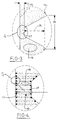
- the electrical discharge roughening method of this invention can be used to prepare the internal cylinder surfaces 11 of bores 20 of a nonferrous or aluminium engine block 12.
- a bank 13 of electrodes 14 (here four in number), each shaped complementary to the bore circumference, are supported for simultaneous insertion into the bores 20.
- Each electrode is carried in a manner to be in precise spaced relationship to the surface 11 during spark roughening, such spaced relationship being a gap 15 of about 40 ⁇ m.
- An electrolyte medium 16 will fill such arcuate gap between the electrodes and the metal wall surface 11 of each bore 20 to be eroded. The electrolyte is introduced into such gap when the block is immersed in a tank 17 containing such electrolyte.
- the electrolyte is circulated through a heat exchanger 19 to maintain its temperature at a low level such as about 18.3°C [65°F].
- the bore surfaces 11 are connected as a cathode in an electrical discharge circuit 18 and the anode electrodes 14 are positioned in close gaped relationship (gap 15) to the bore surfaces 11.
- the gap is filled with the electrolyte 16 containing a halogenated hydrocarbon in an amount of about 2-5% by volume of the electrolyte.
- An AC or DC voltage is imposed in the circuit in pulses between the cathode and anode to effect melting and resolidification of globules of the surface of bores 20.
- Passivation is eliminated by the presence of the halogenated hydrogen. Passivation is defined herein to mean on oxidation or burning of the metal surface leaving an oxide film. It is created with conventional EDM when oxygen in the dielectric or electrolyte combines preferentially with the molecules of the surface being treated to promote an oxide layer that is dimpled like an orange peel. The passivation layer prevents adhesion of coatings thereon because of its very low surface energy and an occluded oxygenated surface layer.
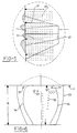
- the anode electrode may be serrated or spiralled (as in Figure 2) to present ridges 22 lying in a common cylindrical envelope 23.
- the tips of the ridges are positioned to create the gap 15 (preferably 0.15-0.56 mm [.006-.022 inches], which is equal to 150-560 microns).
- the length 24 of such electrode is moved along the surface 11 of bore in an circumferential as well as longitudinal manner to influence a desired area of the surface.
- the electrode 14 can be rotated to achieve such movement.
- the surface to be coated is that of a bore liner to be inserted into the bore at some later stage, the liner can be preferentially rotated during electron discharge roughening.
- the electrolyte must be a fluid dielectric that is at least partially conductive such as a hydrocarbon fluid, including kerosene, benzene or freon.
- the dielectric can be water containing alkali impurities as long as the water deionises quickly after electron discharge or sparking therethrough, and additionally acts as an insulator to slow the spread of the plasma for the next sparking pulse.
- the height 25 of the ridges is preferably 225-375 microns, with the pitch 26 in the range of about 775-825 microns.
- the tip 27 of each ridge is preferably spaced a gap distance 15 of about 75-325 microns, although the gap can be as close as 40 microns.
- Figure 4 enlarges zone B of Figure 3 and illustrates how the electric field causes the conductive molecules of particles to form bridges 30 across the field in the gap which results in a breakdown of the dielectric 16. Voltage will fall to a lower level and current will increase to a constant level.
- Figure 6 shows how the plasma channel 33 grows during the pulse "on" time which is a flow of current through the electrolyte due to the bridges 30 that are formed.
- a vapour bubble 34 will form around the plasma channel 33 and the surrounding dense water or dielectric to restrict the plasma growth, concentrating the input energy to a very small volume.
- the plasma temperature may reach high levels such as 40,000 K, and the plasma pressure can rise to as much as 3 kbar.
- the dielectric fluid will solidify this molten material or globules by its temperature differential before such material can be carried away.
- the halogenated hydrocarbons breakdown acting like a conventional flux, to prevent the formation of the occluded oxygen on the resolidified surface. Such cycle would be repeated during a subsequent "on" time of the pulsed current. It is important to realise that no machining takes place, that is, metal removed material is not taken away, only dislodged and reformed.
- the electrical discharge should be run at very low voltages, such as 20-100 volts, with a current amperage at a relatively high level of 40-200 amps, and relatively long on-off spark erosion times (on the order of 100-150 microseconds per spark). Travel of the electrode across the surface to be roughened should be relatively fast such as at the rate of 7.62-15.24 cm/sec [15 to 30 ft/minute].
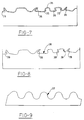
- Comparative analysis of surfaces is prepared using electrical discharge roughening without passivation protection (as in Figure 7) or by conventional machining (as in Figure 9) versus the preparation in accordance with this invention (as in Figure 8).
- the surface in Figure 7 shows a roughened surface with several undercut contours at 35.
- all of the contours have a passivation layer 36 thereon resulting from burning of the aluminium surface using a water or kerosene dielectric; such passivation layer prevents adhesion of applied coatings because of molecular or chemical bonding is reduced or eliminated.
- Grit blasting of the passivated surface can remove the layer in areas that are not undercut, but in the undercut regions, the passivation layer remains and the ridges are usually folded over to close the undercut even more, making the undercuts more difficult to interlock with the coating applied thereover.
- the surface contours of machining is shown on a very magnified cross-sectional basis in Figure 9. It illustrates how rolling and smooth the machined surface 37 can be, resulting from the shearing action of a cutting tool. Such surface 37 does not promote mechanical interlocking with coating thereover.
- the surface 38 in Figure 8 is fresh, devoid of any passivation layer, and presents a random arrangement of rough surface undercuts 39 which promote coating interlock as well as promote chemical and diffusion-type bonding.
- the coating of Figure 8 registered an adhesion strength of at least 55.16 MPa [8000 psi].
Landscapes
- Engineering & Computer Science (AREA)
- Mechanical Engineering (AREA)
- Physics & Mathematics (AREA)
- Chemical & Material Sciences (AREA)
- Thermal Sciences (AREA)
- Plasma & Fusion (AREA)
- Chemical Kinetics & Catalysis (AREA)
- Materials Engineering (AREA)
- Metallurgy (AREA)
- Organic Chemistry (AREA)
- Electrical Discharge Machining, Electrochemical Machining, And Combined Machining (AREA)
Description
Claims (14)
- A method of preparing an electrically conductive surface for receiving a thermally sprayed coating, comprising:melting and rapidly solidifying at least one globules of said surface (11) by spark erosion, said spark erosion being carried out by:(i) connecting the conductive surface (11) as a cathode in a circuit;(ii) positioning an anode electrode (14) close to said conductive surface (11) with a gap (15) there between of .015-.055 centimetres (.006-.022 inches);(iii) filling the gap (15) with a dielectric (16) containing an effective amount of halogenated hydrocarbon that can break down to release nascent halogen atoms for preventing passivation of said surface; and(iv) imposing a pulsed voltage through said dielectric between said cathode (11) and anode (14) to provide cyclical sparking there between that promotes melting and rapid solidification of said at least one globule and releases said nascent halogen.
- A method as claimed in claim 1, in which said halogenated hydrocarbon is present in said dielectric in an amount of 2-5% by weight.
- A method as claimed in claim 1, in which said dielectric is water carrying impurities to promote limited conductivity.
- A method as claimed in claim 1, in which said dielectric is a hydrocarbon fluid selected from the group consisting of kerosene, benzene, carbon tetrachloride, freon, and chloroethane.
- A method as claimed in claim 1, in which during step (iv), said anode is moved to establish multiple sparking sites to roughen a larger defined area of said surface.
- A method as claimed in claim 1, in which said dielectric is continuously cooled to a temperature range of 10-18.3°C (50-65°F).
- A method as claimed in claim 1, in which during step (iv), said voltage is in the range of 20-100 volts, with the current amperage being in the range of 40-200 amps, and the on-off spark erosion time for said voltage being during periods of 100-250 microseconds per spark.
- A method as claimed in claim 1, in which said electrically conductive surface is aluminium-based.
- A method as claimed in claim 1, in which said electrically conductive surface is an iron or copper base alloy.
- A method of making a thermally-coated cylinder bore for a aluminium-based engine block, comprising:(a) cleaning said surface of oil and contaminants;(b) spark eroding said surface by melting and rapidly solidifying micro globules of said surface by imposing a pulse voltage between said surface and an anode electrode held close to said conductive surface within a gap of .15-.055 centimetres (.006-.022 inches), said pulsed voltage being imposed to create a spark through a fluid dielectric filling the gap between said conductive surface and anode electrode, said dielectric containing an effective amount of halogenated hydrocarbons that are effective to break down to release nascent halogen atoms for preventing passivation of the conductive surface;(c) thermally spraying a anti-friction coating onto said spark eroded surface in a thickness of 150-750 microns; and(d) honing said coating to remove 25-30 microns of uniform thickness of said coating to effect the true net shape desired of said coated surface.
- A method as claimed in claim 10, in which the anode electrode is moved along said conductive surface, with the gap spacing therebetween, at a relatively slow rate to effect a desired roughness of said surface, the pulsed voltage being in the range of 20 to 100 volts and the amperage thereof being in the range of 40-200 amps.
- A method as claimed in claim 10, in which said dielectric is water or a fluid hydrocarbon that is effective in promoting spark erosion between said conductive surface and anode electrode when said voltage is imposed.
- A method as claimed in claim 10, in which said anti-friction coating is comprised of a lubricating oxide or a metal solid lubricant mixture, or solid lubricant selected from the group consisting of graphite, molybdenum disulphide, and boron nitride carried in a thermoset polymer properly cured at appropriate curing temperature of 93.3-204.4°C [200°-400°F].
- A method as claimed in claim 10, in which said honing is carried out in three stages utilising honing stones of standard grit sizes ranging from 100 to 600 in said stages.
Applications Claiming Priority (2)
| Application Number | Priority Date | Filing Date | Title |
|---|---|---|---|
| US314014 | 1994-09-28 | ||
| US08/314,014 US5648122A (en) | 1994-09-28 | 1994-09-28 | Using electrical discharge surface preparation for thermal coatings |
Publications (2)
| Publication Number | Publication Date |
|---|---|
| EP0704271A1 EP0704271A1 (en) | 1996-04-03 |
| EP0704271B1 true EP0704271B1 (en) | 1998-12-09 |
Family
ID=23218166
Family Applications (1)
| Application Number | Title | Priority Date | Filing Date |
|---|---|---|---|
| EP95306162A Expired - Lifetime EP0704271B1 (en) | 1994-09-28 | 1995-09-04 | Surface preparation for thermal coatings |
Country Status (4)
| Country | Link |
|---|---|
| US (1) | US5648122A (en) |
| EP (1) | EP0704271B1 (en) |
| CA (1) | CA2159139A1 (en) |
| DE (1) | DE69506507D1 (en) |
Families Citing this family (18)
| Publication number | Priority date | Publication date | Assignee | Title |
|---|---|---|---|---|
| JP3563203B2 (en) * | 1996-06-12 | 2004-09-08 | 独立行政法人 科学技術振興機構 | Surface treatment method by electric discharge machining and its apparatus |
| US6017591A (en) * | 1996-11-14 | 2000-01-25 | Ford Global Technologies, Inc. | Method of making adherently sprayed valve seats |
| US6141870A (en) | 1997-08-04 | 2000-11-07 | Peter K. Trzyna | Method for making electrical device |
| US20050016705A1 (en) * | 2003-07-21 | 2005-01-27 | Ford Motor Company | Method and arrangement for an indexing table for making spray-formed high complexity articles |
| DE102006004769B4 (en) * | 2006-02-02 | 2022-05-25 | Mercedes-Benz Group AG | Surface conditioning for thermal spray coatings |
| US7749050B2 (en) * | 2006-02-06 | 2010-07-06 | Chien-Min Sung | Pad conditioner dresser |
| US7816619B2 (en) * | 2007-03-21 | 2010-10-19 | Nebojsa Jaksic | Methods and apparatus for manufacturing carbon nanotubes |
| US20090127231A1 (en) * | 2007-11-08 | 2009-05-21 | Chien-Min Sung | Methods of Forming Superhard Cutters and Superhard Cutters Formed Thereby |
| DE102009027200B3 (en) * | 2009-06-25 | 2011-04-07 | Ford Global Technologies, LLC, Dearborn | Method for roughening metal surfaces, use of the method and workpiece |
| US8455783B2 (en) * | 2009-08-27 | 2013-06-04 | Mcmaster University | Electro-erosion edge honing of cutting tools |
| DE102011086803A1 (en) | 2011-11-22 | 2013-05-23 | Ford Global Technologies, Llc | Repair method of a cylinder surface by means of plasma spraying |
| DE102013200912B4 (en) | 2012-02-02 | 2018-05-30 | Ford Global Technologies, Llc | crankcase |
| US9511467B2 (en) | 2013-06-10 | 2016-12-06 | Ford Global Technologies, Llc | Cylindrical surface profile cutting tool and process |
| US8726874B2 (en) | 2012-05-01 | 2014-05-20 | Ford Global Technologies, Llc | Cylinder bore with selective surface treatment and method of making the same |
| US9079213B2 (en) | 2012-06-29 | 2015-07-14 | Ford Global Technologies, Llc | Method of determining coating uniformity of a coated surface |
| US9382868B2 (en) | 2014-04-14 | 2016-07-05 | Ford Global Technologies, Llc | Cylinder bore surface profile and process |
| US10220453B2 (en) | 2015-10-30 | 2019-03-05 | Ford Motor Company | Milling tool with insert compensation |
| CN107931762B (en) * | 2017-11-09 | 2020-12-04 | 广东工业大学 | A method for preparing copper anti-fouling micro-nano composite structure layer by electrical discharge machining |
Family Cites Families (13)
| Publication number | Priority date | Publication date | Assignee | Title |
|---|---|---|---|---|
| DE1293515B (en) * | 1963-06-26 | 1969-04-24 | Pevar Maxwell | Process for improving the adhesive strength of metal layers applied to a base metal, in particular by metal spraying |
| NL130914C (en) * | 1964-05-26 | |||
| US3626137A (en) * | 1970-03-25 | 1971-12-07 | Amsted Ind Inc | Method of electrical discharge machining |
| US4219718A (en) * | 1978-07-13 | 1980-08-26 | Mitsubishi Denki Kabushiki Kaisha | Process and apparatus for electrical discharge machining of cylindrical work |
| US4416751A (en) * | 1980-03-24 | 1983-11-22 | General Electric Co. | Process for producing a ferrofluid |
| JPS5856737A (en) * | 1981-09-30 | 1983-04-04 | Nippon Kokan Kk <Nkk> | Electric spark machining method for roll-like workpiece |
| DE3216456A1 (en) * | 1982-05-03 | 1983-11-03 | Robert Bosch Gmbh, 7000 Stuttgart | METHOD FOR Embedding Hard Materials In The Surface Of Chip Removal Tools |
| DE3426201A1 (en) * | 1984-07-17 | 1986-01-23 | BBC Aktiengesellschaft Brown, Boveri & Cie., Baden, Aargau | PROCESS FOR APPLYING PROTECTIVE LAYERS |
| US4735678A (en) * | 1987-04-13 | 1988-04-05 | Olin Corporation | Forming a circuit pattern in a metallic tape by electrical discharge machining |
| SU1687629A1 (en) * | 1989-01-16 | 1991-10-30 | Физико-технический институт АН БССР | Method of surface hardening of metallic components |
| JP2586986B2 (en) * | 1992-04-28 | 1997-03-05 | プログレツシイヴ ブラ−ステイング システムズ インコ−ポレイテツド | Apparatus and method for blasting metal surfaces |
| DE4238369C2 (en) * | 1992-11-13 | 1996-09-26 | Mtu Muenchen Gmbh | Component made of a metallic base substrate with a ceramic coating |
| US5302450A (en) * | 1993-07-06 | 1994-04-12 | Ford Motor Company | Metal encapsulated solid lubricant coating system |
-
1994
- 1994-09-28 US US08/314,014 patent/US5648122A/en not_active Expired - Lifetime
-
1995
- 1995-09-04 EP EP95306162A patent/EP0704271B1/en not_active Expired - Lifetime
- 1995-09-04 DE DE69506507T patent/DE69506507D1/en not_active Expired - Lifetime
- 1995-09-26 CA CA002159139A patent/CA2159139A1/en not_active Abandoned
Also Published As
| Publication number | Publication date |
|---|---|
| DE69506507D1 (en) | 1999-01-21 |
| US5648122A (en) | 1997-07-15 |
| CA2159139A1 (en) | 1996-03-29 |
| EP0704271A1 (en) | 1996-04-03 |
Similar Documents
| Publication | Publication Date | Title |
|---|---|---|
| US5648122A (en) | Using electrical discharge surface preparation for thermal coatings | |
| Ekmekci et al. | A comparative study on the surface integrity of plastic mold steel due to electric discharge machining | |
| US6899798B2 (en) | Reusable ceramic-comprising component which includes a scrificial surface layer | |
| Lau et al. | Electrical discharge machining of carbon fibre composite materials | |
| JP4739368B2 (en) | Sputtering target with less generation of particles, backing plate, apparatus in sputtering apparatus, and roughening method | |
| Datta | Fabrication of an array of precision nozzles by through‐mask electrochemical micromachining | |
| EP0716158B1 (en) | Method of making engine blocks with coated cylinder bores | |
| CA2159140C (en) | High speed electrical discharge surface preparation of internal surfaces for thermal coatings | |
| US5698114A (en) | Surface layer forming process using electric discharge machining | |
| EP0548932B1 (en) | Surface layer forming process using electric discharge machining | |
| Choudhary et al. | Analysis and evaluation of heat affected zones in electric discharge machining of EN-31 die steel | |
| Rao et al. | Surface modification by electro-discharge machining using powder metallurgy electrode: a review | |
| Rao et al. | Influence of machining parameters on electric discharge machining of maraging steels–An experimental investigation | |
| Jahan et al. | Nanofinishing of hard materials using micro-electrodischarge machining | |
| US7834291B2 (en) | Electrode for electric discharge surface treatment, and method and apparatus for electric discharge surface treatment | |
| KR20170004970A (en) | Method for delamination of ceramic hard material layers from steel and cemented carbide substrates | |
| Kumar et al. | Comparison of material transfer in electrical discharge machining of AISI H13 die steel | |
| JPH09136260A (en) | Cooling hole machining method for gas turbine blade | |
| Rajesha et al. | Some aspects of surface integrity study of electro discharge machined Inconel 718 | |
| EP1524050A2 (en) | Wear-resisting surface structure | |
| Singh et al. | Electric discharge drilling with gas-assisted multi-hole slotted tool | |
| Khan et al. | The effect of EDM with external magnetic field on surface roughness of stainless steel | |
| Fedorov et al. | The Influence of Steel 35 Wire EDM Parameters on the Surface Roughness and Morphology. | |
| Paswan et al. | Exploring powder mixed electrical discharge machining (PMEDM) | |
| US8455783B2 (en) | Electro-erosion edge honing of cutting tools |
Legal Events
| Date | Code | Title | Description |
|---|---|---|---|
| PUAI | Public reference made under article 153(3) epc to a published international application that has entered the european phase |
Free format text: ORIGINAL CODE: 0009012 |
|
| AK | Designated contracting states |
Kind code of ref document: A1 Designated state(s): DE FR GB |
|
| 17P | Request for examination filed |
Effective date: 19960830 |
|
| GRAG | Despatch of communication of intention to grant |
Free format text: ORIGINAL CODE: EPIDOS AGRA |
|
| 17Q | First examination report despatched |
Effective date: 19980123 |
|
| GRAG | Despatch of communication of intention to grant |
Free format text: ORIGINAL CODE: EPIDOS AGRA |
|
| GRAH | Despatch of communication of intention to grant a patent |
Free format text: ORIGINAL CODE: EPIDOS IGRA |
|
| GRAH | Despatch of communication of intention to grant a patent |
Free format text: ORIGINAL CODE: EPIDOS IGRA |
|
| GRAA | (expected) grant |
Free format text: ORIGINAL CODE: 0009210 |
|
| AK | Designated contracting states |
Kind code of ref document: B1 Designated state(s): DE FR GB |
|
| REF | Corresponds to: |
Ref document number: 69506507 Country of ref document: DE Date of ref document: 19990121 |
|
| ET | Fr: translation filed | ||
| PG25 | Lapsed in a contracting state [announced via postgrant information from national office to epo] |
Ref country code: DE Free format text: LAPSE BECAUSE OF FAILURE TO SUBMIT A TRANSLATION OF THE DESCRIPTION OR TO PAY THE FEE WITHIN THE PRESCRIBED TIME-LIMIT Effective date: 19990310 |
|
| PLBE | No opposition filed within time limit |
Free format text: ORIGINAL CODE: 0009261 |
|
| STAA | Information on the status of an ep patent application or granted ep patent |
Free format text: STATUS: NO OPPOSITION FILED WITHIN TIME LIMIT |
|
| 26N | No opposition filed | ||
| REG | Reference to a national code |
Ref country code: FR Ref legal event code: TP Ref country code: FR Ref legal event code: CD |
|
| REG | Reference to a national code |
Ref country code: GB Ref legal event code: IF02 |
|
| REG | Reference to a national code |
Ref country code: GB Ref legal event code: 746 Effective date: 20050112 |
|
| REG | Reference to a national code |
Ref country code: FR Ref legal event code: CD Ref country code: FR Ref legal event code: CA |
|
| PGFP | Annual fee paid to national office [announced via postgrant information from national office to epo] |
Ref country code: GB Payment date: 20060804 Year of fee payment: 12 |
|
| PGFP | Annual fee paid to national office [announced via postgrant information from national office to epo] |
Ref country code: FR Payment date: 20060906 Year of fee payment: 12 |
|
| GBPC | Gb: european patent ceased through non-payment of renewal fee |
Effective date: 20070904 |
|
| REG | Reference to a national code |
Ref country code: FR Ref legal event code: ST Effective date: 20080531 |
|
| PG25 | Lapsed in a contracting state [announced via postgrant information from national office to epo] |
Ref country code: FR Free format text: LAPSE BECAUSE OF NON-PAYMENT OF DUE FEES Effective date: 20071001 |
|
| PG25 | Lapsed in a contracting state [announced via postgrant information from national office to epo] |
Ref country code: GB Free format text: LAPSE BECAUSE OF NON-PAYMENT OF DUE FEES Effective date: 20070904 |