EP0703551B1 - A token discriminating device - Google Patents
A token discriminating device Download PDFInfo
- Publication number
- EP0703551B1 EP0703551B1 EP95114918A EP95114918A EP0703551B1 EP 0703551 B1 EP0703551 B1 EP 0703551B1 EP 95114918 A EP95114918 A EP 95114918A EP 95114918 A EP95114918 A EP 95114918A EP 0703551 B1 EP0703551 B1 EP 0703551B1
- Authority
- EP
- European Patent Office
- Prior art keywords
- token
- discriminating
- rolling
- unacceptable
- smaller
- Prior art date
- Legal status (The legal status is an assumption and is not a legal conclusion. Google has not performed a legal analysis and makes no representation as to the accuracy of the status listed.)
- Expired - Lifetime
Links
Images


Classifications
-
- G—PHYSICS
- G07—CHECKING-DEVICES
- G07D—HANDLING OF COINS OR VALUABLE PAPERS, e.g. TESTING, SORTING BY DENOMINATIONS, COUNTING, DISPENSING, CHANGING OR DEPOSITING
- G07D5/00—Testing specially adapted to determine the identity or genuineness of coins, e.g. for segregating coins which are unacceptable or alien to a currency
- G07D5/02—Testing the dimensions, e.g. thickness, diameter; Testing the deformation
-
- G—PHYSICS
- G07—CHECKING-DEVICES
- G07D—HANDLING OF COINS OR VALUABLE PAPERS, e.g. TESTING, SORTING BY DENOMINATIONS, COUNTING, DISPENSING, CHANGING OR DEPOSITING
- G07D3/00—Sorting a mixed bulk of coins into denominations
- G07D3/02—Sorting coins by means of graded apertures
- G07D3/04—Sorting coins by means of graded apertures arranged on an inclined rail
-
- G—PHYSICS
- G07—CHECKING-DEVICES
- G07D—HANDLING OF COINS OR VALUABLE PAPERS, e.g. TESTING, SORTING BY DENOMINATIONS, COUNTING, DISPENSING, CHANGING OR DEPOSITING
- G07D3/00—Sorting a mixed bulk of coins into denominations
- G07D3/12—Sorting coins by means of stepped deflectors
- G07D3/121—Sorting coins by means of stepped deflectors arranged on inclined paths
- G07D3/123—Sorting coins by means of stepped deflectors arranged on inclined paths the coins being deflected off rails
Definitions
- This invention relates to a token discriminating device, particularly to a token discriminating device which is disposed in a token chute portion od a token game machine to discriminate acceptable tokens from unacceptable tokens according to the size of the token.
- the EP-A-0 288 955 discloses a coin separator which comprises a primary coin race along which inserted coins are travelling. An aperture runs along the primary coin race and communicates between this race and a secondary coin race which runs parallel to the first coin race.
- the aperture between the two coin races is bounded above and below by upper and lower flanges, respectively. These flanges extend laterally into the aperture, having distances sufficient to engage the upper and the lower edges of a selected coin, but insufficient to engage the similar edges of smaller coins.
- a protrusion is formed in the primary coin race opposite to the aperture and the secondary coin race. This protrusion deflects the coins travelling along the primary coin race toward the aperture.
- the protrusion causes each coin to experience a lateral change of direction in the general direction of the aperture. If the coin has the desired size, the upper and lower edges of the coin will encounter the upper and lower flanges and continue travelling along the primary coin range. If a coin is smaller than the specified size the bottom edge will initially engage the lower flange, but the upper edge will not engage the upper flange. Then the lateral thrust imparted by the protrusion causes the upper edge of the coin to pass under the upper flange and through the aperture into the secondary coin race.
- This coin separator mainly consists of solid parts manufactured by casting or milling, which results in high production costs. Further, an adjustment is hardly possible, as complete solid parts have to be changed. Therefore also a readjustment during maintenance is very difficult.
- the US-A-1 556 477 shows a coin detector which comprises a chute of substantially U-shape in cross section.
- the chute is provided with two laterally inclined side walls connected by a bight portion at their lower end.
- One of the side walls is partially cut away or recessed out from its upper end and the lower portion defined between the recess and the bight is inclined laterally to provide a guide wing.
- a strip is attached to the chute above the recess.
- the lower edge of the strip and the bight define two bearing surfaces upon which a coin of proper diameter will roll in an inclined position, the coin being induced to this position by the second inclined side wall.
- a coin of a smaller diameter will not ride along the lower edge of the strip and therefore laterally fall against the guide wing where it will be discharged.
- the coin is deflected by one of the inclined walls in a inclined position.
- the complete side wall is inclined to form a deflector it is difficult to adjust the complete device it is nearly impossible to readjust the deflector after a term of use. Further, manufacturing of this device is complicated, because the chute consists of several parts and has a complex shape.
- DE-C-154 766 shows a coin discriminating device, wherein a coin is rolled in a rolling passage, formed by a solid rear wall, a partially cut away front wall and a bottom.
- the partially cut away front wall consists of a guiding web at the bottom and a guiding web at the top of the rolling passage.
- the distance between the edge of the top guiding web and the bottom of the rolling passage is just a bit smaller than the acceptable coins.
- a portion of the rolling passage is designed to discriminate coins, which are too small.
- a deflector extending inwardly is positioned on the inner surface of the rear wall.
- the top guiding web is bent outwardly, while the guiding web at the bottom is partly cut away defining a discrimination opening in the guiding web at the bottom.
- Coins passing through the rolling passage are deflected by the deflector in direction to the front wall.
- Coins of an acceptable diameter are still guided by the top guiding web, while smaller coins are not guided by the top guiding web.
- the bottom guiding web is cut away in this portion of the rolling passage, the smaller coins are not guided any longer and as they are deflected by the deflector they fall out of the rolling passage through the discrimination opening.
- the deflector has a closed bulged shape which is formed as a separate, solid part. It is difficult to adjust the deflector, especially if a readjustment becomes necessary after a term of use.
- the present invention is directed to a token discriminating device comprising: a rolling member including two guide walls and a bottom for defining a rolling passage in which a token is rolled; and a smaller unacceptable token discriminating portion including: a cut-away portion formed in one of the two guide walls; a deflective wall provided in an upper portion of the cut-away portion to define a discriminating opening, a discriminating distance between the bottom of the rolling member and a lower end of the deflective wall being smaller than the diameter of an acceptable token, the deflective wall being bent outward of the rolling passage; a deflector provided on the other guide wall at a position facing the discriminating opening for deflecting a rolling token to the discriminating opening, the deflector being formed by a cut portion which is bent inwardly from the inner surface of the guide wall.
- the deflective wall may be preferably constructed by a band member bent outward of the rolling passage; and a supporting portion which is formed in an upper portion of the cut-away portion and supports the band member slidably in the height direction of the guide wall.
- the larger unacceptable token discriminating portion may be defined by providing two restrictive members in an upstream end of the rolling passage, and spacing the two restrictive members by distance slightly larger than the diameter of an acceptable token. It may be preferable to make one of the two restrictive members fixed and make the other restrictive member movable.
- the outward-bent deflective wall is provided in an upper portion of the cut-away portion to define the discriminating opening and the deflector is provided on the opposite guide wall.
- Rolling tokens are deflected or inclined to the discriminating opening from which unacceptable tokens then fall by the weight. Acceptable tokens roll along the deflective wall and then rolls in the main rolling passage. Accordingly, even in the state where the deflector is projected in the rolling passage, the deflective wall permits tokens to roll down smoothly, and eliminates the likelihood that tokens is stopped by the deflector.
- the deflective wall is constructed by the band member slidably supported by the support portion. Accordingly, the space of the discriminating opening can be desirably changed, and a variety of tokens having different sizes can be thus discriminated by one rolling member.
- the deflector is fixedly provided on the other guide wall. This will simplify the construction of the token discriminating device and ensure a prolonged operation without maintenance service, thus enabling lower production and running costs.
- the larger unacceptable token discriminating portion is formed on an upstream of the smaller unacceptable token discriminating portion. Accordingly, unacceptable tokens having larger diameters that the diameter of the acceptable token can be discriminated off in addition to the discrimination of the smaller unacceptable tokens.
- the larger unacceptable token discriminating portion is defined by two restrictive members only. Accordingly, its construction is very simple. Also, since one of the two restrictive members is made to be movable, the size of the discriminating opening can be changed easily by moving the movable restrictive member.
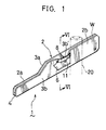
- the token discriminating device 1 includes a rolling member 2 which is in the form of a channel and has a specified length in a rolling direction. A token is rolled in the rolling member 2.
- the rolling member 2 is supported by a support pole 20 in a posture of declining in such an angle that a token rolls down by its weight.
- the rolling member 2 includes guide walls 3a, 3b and a bottom member 4.
- the guide walls 3a, 3b face each other at a specified gap.
- the gap between the guide walls 3a, 3b is slightly larger than the thickness of the token to be rolled down in the rolling member 2.
- the bottom member 4 is disposed at a bottom of the guide walls 3a, 3b and connect the guide walls 3a, 3b to each other.
- the guide walls 3a, 3b and the bottom member 4 define a rolling passage 5 in which a token is to be rolled.
- the rolling member 2 has an outlet portion 2a and an inlet/discriminating portion 2b.
- the guide walls 3a, 3b in the outlet portion 2a are made to have a height smaller than the diameter of an acceptable token so that the passing of the token can be checked.
- the inlet/discriminating portion 2b is provided with a larger unacceptable token discriminating portion A and a smaller unacceptable token discriminating portion B.
- the larger unacceptable token discriminating portion A is located on upstream of the smaller unacceptable token discriminating portion B.
- the larger unacceptable token discriminating portion A is defined by a lower restrictive member 12 and an upper restrictive member 15.
- the two restrictive members 12 and 15 are placed in the gap between the guide walls 3a, 3b.
- the lower restrictive member 12 is disposed on an inlet end portion of the bottom member 4 of the rolling member 2, and generally has a trapezoid shape.
- the lower restrictive member 12 is releasably attached on the guide walls 3a, 3b by a screw 14 passing an oblong hole 13 formed in the guide wall 3b.
- the lower restrictive member 12 is permitted to slide on the bottom member 4 in a lengthwise direction of the rolling member 2 within a length of the oblong hole 13 by releasing the screw 14.
- the upper restrictive member 15 is disposed in an upper portion of the inlet end portion of the rolling member 2 and downstream of the lower restrictive member 12, and has a rectangular shape.
- the upper restrictive member 15 is fixedly attached on the guide walls 3a, 3b.
- the lower and upper restrictive members 12 and 15 are spaced from each other so that a token inlet passage W is defined between them.
- the token inlet passage W has a discriminating throat T which is defined by a smallest space between a lower right corner 15a of the upper restrictive member 15 and a slanting surface 12a of the lower restrictive member 12.
- the space distance D of the discriminating throat T is equal to or slightly larger than the diameter of an acceptable token. Tokens having a diameter larger than the space distance D are kept from passing while tokens having a diameter equal to or smaller than the space distance D are permitted to pass. In this way, unacceptable tokens having a diameter larger than the diameter of an acceptable token are discriminated off.
- the space distance D is changed by sliding the lower restrictive member 12.
- the smaller unacceptable token discriminating portion B is defined by a cut-away portion 6 formed in an intermediate of the guide wall 3b, a deflective wall 3b', and a deflector 11 formed in an intermediate of the guide wall 3a.
- the cut-away portion 6 has a length equal to or slightly larger than the diameter of the acceptable token.
- a lower end of the cut-away portion 6 is positioned slightly higher than a top surface of the bottom member 4 so that a low guide wall exists in a lower portion of the smaller unacceptable token discriminating portion B.
- the low guide wall is not so high as to support or keep tokens from falling from the cut-away portion 6.
- the low guide wall is provided to merely guide a lower portion of rolling tokens.
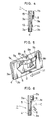
- the deflective wall 3b' is formed by a band member 8 and support arm portions 7a and 7b. As shown in Fig. 5, the support arm portions 7a and 7b are provided in an upper portion of the cut-away portion 6. The support arm portion 7a extends from a downstream side of the cut-away portion 6 while the support arm portion 7b extends from an upstream side of the cut-away portion 6. Also, the support arm portions 7a and 7b are bent outward from the guide wall 3b. Further, the support arm portion 7a is formed with a through-hole for passing a screw 9a and the support arm portion 7b is formed with a thread hole for engaging with a screw 9b. The screws 9a and 9b will described below.
- the band member 8 is attached on the support arm portions 7a and 7b.
- the band member 8 has an intermediate portion 8a, a downstream portion 8b, and an upstream portion 8c.
- the downstream and upstream portions 8b and 8c are respectively formed with oblong holes 10a and 10b.
- the oblong holes 10a and 10b extend in a vertical direction.
- the upstream portion 8c is bent inward at the same angle as the support arm portion 7b and is releasably attached onto an outer surface of the support arm portion 7b by engaging the screw 9b passing through the oblong hole 10b with the threaded hole formed in the support arm portion 7b.
- the downstream portion 8b is bent inward at the same angle as the support arm portion 7a and is releasably attached to an inner surface of the support arm portion 7a by engaging the screw 9a passing the through-hole formed in the support arm portion 7a with a plate nut provided on an inner surface of the downstream portion 8b.
- a discriminating opening O is defined by the cut-away portion 6 and the band member 8.
- the band member 8 is set in such a position that a discriminating distance between a bottom end of the band member 8 and the top surface of the bottom member 4 is slightly smaller than the diameter of the acceptable token. Accordingly, unacceptable token having a diameter smaller than the discriminating distance are fallen off from the discriminating opening O because there is not any portion for keeping the unacceptable small token from falling.
- the discriminating distance is changed by releasing the screws 9a and 9b and sliding the band member 8 vertically along the oblong holes 10a and 10b.
- the upstream portion 8c of the band member 8 is attached onto the outer surface of the support arm portion 7b while the downstream portion 8b is attached onto the inner surface of the support arm portion 7a.
- the support arm portion 7b is positioned inside relative to the band member 8.
- the band member 8 is positioned inside relative to the support arm portion 7a.
- the deflector 11 is formed in the guide wall 3a at a position opposite to the discriminating opening O of the cut-away portion 6.
- the deflector 11 is projected in the rolling passage 5 so as to deflect a rolling token to the discriminating opening O. This will ensure the discrimination of unacceptable token having a smaller diameter than the discriminating distance.
- the defector 11 is formed by making a cut in the specified portion of the guide wall 3a and bending the cut portion inward.
- the deflective wall 3b' is formed by the combination of the outward-bent support arm portions 7a, 7b and the outward-bent band member 8. Accordingly, although the deflector 11 is fixedly projected in the rolling passage, there is no likelihood that the rolling token is stopped at the deflector 11 because the rolling token inclines to the deflective wall 3b'.
- a token is inserted in the token inlet passage W formed in the larger unacceptable token discriminating portion A where it is discriminated whether the inserted token is larger than the predetermined diameter of the acceptable token. Specifically, if the inserted token is larger than the predetermined diameter, the inserted token is blocked from passing at the discriminating throat T which is defined by the lower right corner 15a of the upper restrictive member 15 and the slanting surface 12a of the lower restrictive member 12 and is set at a distance D equal to or slightly larger than the diameter of the acceptable token. On the other hand, if the inserted token is smaller than the predetermined diameter, the inserted token passes through the discriminating throat T of the larger unacceptable token discriminating portion A.
- the passed token rolls down in the rolling passage 5 to the smaller unacceptable token discriminating portion B where it is discriminated whether the token is smaller than the predetermined diameter of the acceptable token.
- the rolling token comes into contact with the deflector 11. Consequently, the rolling token is inclined toward the discriminating opening O formed in the smaller unacceptable token discriminating portion B.
- the acceptable token M even when being inclined toward the discriminating opening O, is prevented from falling from the discriminating opening O by the band member 8, and then passes the smaller unacceptable token discriminating portion B.
- the unacceptable token C having a diameter smaller than the discriminating distance is fallen from the discriminating opening O by the deflecting force of the deflector. In this way, unacceptable tokens are discriminated off in the smaller unacceptable token discriminating portion B.
- the lower restrictive member 12 in the larger unacceptable token discriminating portion A is slidingly moved in the lengthwise direction of the rolling member 2 to vary the distance D of the discriminating throat T, or the band member 8 in the smaller unacceptable token discriminating portion B is vertically moved to adjust the discriminating distance.
- Tokens which have passed the smaller unacceptable token discriminating portion B are judged to be the acceptable token and supplied to an appropriate portion of the game.
- the discriminating opening O of the smaller unacceptable token discriminating portion B is defined in one of the two guide walls defining the rolling passage 5, i.e., the guide wall 3b, by the cut-away portion 6 and the band member 8.
- the deflector 11 is fixedly formed in the opposite guide wall 3a at a position facing the discriminating opening 0.
- the rolling token is forcibly inclined to the discriminating opening O by the deflector 11, and is then discriminated in the discriminating opening O whether or not to have a smaller diameter than the diameter of the acceptable token. Accordingly, since the rolling token is forcibly inclined to the discriminating opening O, the discrimination is reliably carried out irrespective of its installation state.
- the discriminating device does not have any moving parts. Accordingly, the construction is very simple and little wear occurs, which thus makes it possible to reduce the production costs and to eliminate maintenance service.
- the size of the discriminating opening O is changed merely by releasing the screws 9a, 9b and sliding the band member 8 in the vertical direction. Accordingly, the token discriminating device of the invention can be used for a wide variety of game machines each using different size tokens.
- the larger unacceptable token discriminating portion A On upstream of the smaller unacceptable token discriminating portion B is provided the larger unacceptable token discriminating portion A.
- the larger unacceptable token is prevented from rolling down to the smaller unacceptable token discriminating portion B. Accordingly, larger and smaller unacceptable tokens can be both discriminated off reliably.
- the deflector 11 is formed by making a cut in a middle portion of the guide wall 3a and bending the cut portion inward.
- a single smaller unacceptable token discriminating portion B there is provided a single smaller unacceptable token discriminating portion B.
- a plurality of smaller unacceptable token discriminating portions may be provided step by step in the lengthwise direction of the rolling member 2 to sort smaller unacceptable tokens in accordance with their sizes. For example, in order of the rolling direction, there are provided a first discriminating portion having a smallest discriminating opening O for discriminating off smallest unacceptable token, a second discriminating portion having an intermediate discriminating opening O for discriminating off intermediate small tokens, and a third discriminating portion having a relatively large discriminating opening O for discriminating off relatively large tokens.
- the discriminating distance of the smaller unacceptable token discriminating portion B is constant in the rolling direction.
- the discriminating distance of a single smaller unacceptable token discriminating portion B may be changed in the rolling direction to sort smaller unacceptable tokens in accordance with their sizes.
- the discriminating distance of a single smaller unacceptable token discriminating portion is made to be smallest at an upstream portion to discriminate off smallest unacceptable token, and is made to be intermediate at an intermediate portion to discriminate off intermediate small tokens, and is made to be relatively large at a downstream portion to discriminate off relatively large tokens.
Landscapes
- Physics & Mathematics (AREA)
- General Physics & Mathematics (AREA)
- Testing Of Coins (AREA)
- Control Of Vending Devices And Auxiliary Devices For Vending Devices (AREA)
Description
Claims (7)
- A token discriminating device comprising:characterized in thata rolling member (2) including two guide walls (3a, 3b) and a bottom (4) for defining a rolling passage (5) in which a token is rolled; anda smaller unacceptable token discriminating portion (B) including:a cut-away portion formed in one (3b) of the two guide walls;a deflective wall (3b') provided in an upper portion of the cut-away portion (6) to define a discriminating opening (O), a discriminating distance between the bottom (4) of the rolling member (2) and a lower end of the deflective wall (3b') being smaller than the diameter of an acceptable token, the deflective wall (3b') being bent outward of the rolling passage (5);a deflector (11) provided on the other guide wall (3a) at a position facing the discriminating opening (O) for deflecting a rolling token to the discriminating opening (O),
the deflector (11) is formed by a cut portion (11) which is bent inwardly from the inner surface of the guide wall (3a). - A token discriminating device according to claim 1, characterized in that the cut portion (11) has a substantially rectangular shape.
- A token discriminating device according to claim 1 or 2, characterized in that the end of the cut portion (11) is the most inwardly bent portion thereof and the amount of bending does not vary with the height of the cut portion (11) from the bottom wall of the rolling passage (5).
- A token discriminating device according to one of the preceding claims, characterized in that the deflective wall (3b') includes:
a band member (8) bent outward of the rolling passage (5); and a supporting portion (7a, 7b) which is formed in an upper portion of the cut-away portion (6) and supports the band member (8) slidable in the height direction of the guide wall (3b). - A token discriminating device according to one of the preceding claims, further characterized by a larger unacceptable token discriminating portion (A) formed in the rolling member (2) in a position upstream of the smaller unacceptable token discriminating portion (B).
- A token discriminating device according to claim 5, characterized in that the larger unacceptable token discriminating portion (A) includes two restrictive members (12, 15) provided in an upstream end of the rolling passage (5), the two restrictive members (12, 15) being spaced by distance (D) slightly larger than the diameter of an acceptable token.
- A token discriminating device according to claim 5 or 6, characterized in that one of the two restrictive members (15) is fixedly provided and the other restrictive member (12) is movably provided.
Applications Claiming Priority (2)
| Application Number | Priority Date | Filing Date | Title |
|---|---|---|---|
| JP6252761A JP3072298B2 (en) | 1994-09-22 | 1994-09-22 | Medal sorting device |
| JP252761/94 | 1994-09-22 |
Publications (2)
| Publication Number | Publication Date |
|---|---|
| EP0703551A1 EP0703551A1 (en) | 1996-03-27 |
| EP0703551B1 true EP0703551B1 (en) | 1998-12-02 |
Family
ID=17241931
Family Applications (1)
| Application Number | Title | Priority Date | Filing Date |
|---|---|---|---|
| EP95114918A Expired - Lifetime EP0703551B1 (en) | 1994-09-22 | 1995-09-21 | A token discriminating device |
Country Status (5)
| Country | Link |
|---|---|
| US (1) | US5706927A (en) |
| EP (1) | EP0703551B1 (en) |
| JP (1) | JP3072298B2 (en) |
| DE (1) | DE69506353T2 (en) |
| TW (1) | TW307402U (en) |
Families Citing this family (3)
| Publication number | Priority date | Publication date | Assignee | Title |
|---|---|---|---|---|
| US6758736B1 (en) * | 1997-06-20 | 2004-07-06 | Victor G. Ristvedt | Coin or token sorting apparatus |
| US6109417A (en) * | 1998-11-03 | 2000-08-29 | Parkway Machine Corporation | Anti-corruption coin/token input chute |
| CN105427454A (en) * | 2015-12-16 | 2016-03-23 | 广东工业大学 | Coin classification mechanism |
Family Cites Families (11)
| Publication number | Priority date | Publication date | Assignee | Title |
|---|---|---|---|---|
| DE154766C (en) * | ||||
| US1556477A (en) * | 1924-12-03 | 1925-10-06 | Walter C Bellows | Coin detector |
| GB374468A (en) * | 1930-03-10 | 1932-06-10 | Zwietusch E & Co Gmbh | Improvements in or relating to coin-freed apparatus |
| DE3007048A1 (en) * | 1980-02-26 | 1981-09-03 | Paul 4992 Espelkamp Gauselmann | Electrically operated slot machine using digital logic - has built-in memory for operation and evaluation of combinations, using operation cycle based upon double win possibility |
| DE3007484A1 (en) * | 1980-02-28 | 1981-09-10 | Löwen-Automaten Gerhard W. Schulze GmbH & Co KG, 6530 Bingen | Coin tester inlet channel - has deflector forcing smaller dia. coins into recess in side wall for rejection |
| JPS6059632B2 (en) | 1980-06-24 | 1985-12-26 | 富士電機株式会社 | Coin diameter sorting device |
| US4676358A (en) * | 1985-10-28 | 1987-06-30 | Rosendahl Jr Warren G | Coin control system |
| US4911280A (en) * | 1987-04-27 | 1990-03-27 | Bruner Philemon L | Method and apparatus for deflecting coins while maintaining an on-edge orientation |
| US4987989A (en) * | 1989-07-24 | 1991-01-29 | Buckenham Nicholas H | Coin-freed vending machine mechanism |
| JPH0358489A (en) * | 1989-07-26 | 1991-03-13 | Fuji Electric Co Ltd | Laminated type piezoelectric element |
| JPH0659632A (en) * | 1992-08-07 | 1994-03-04 | Rika Kogyo Kk | Optical display device |
-
1994
- 1994-09-22 JP JP6252761A patent/JP3072298B2/en not_active Expired - Fee Related
-
1995
- 1995-09-21 DE DE69506353T patent/DE69506353T2/en not_active Expired - Fee Related
- 1995-09-21 EP EP95114918A patent/EP0703551B1/en not_active Expired - Lifetime
- 1995-09-22 US US08/532,446 patent/US5706927A/en not_active Expired - Lifetime
- 1995-09-23 TW TW085214959U patent/TW307402U/en unknown
Also Published As
| Publication number | Publication date |
|---|---|
| DE69506353D1 (en) | 1999-01-14 |
| TW307402U (en) | 1997-06-01 |
| JPH0896198A (en) | 1996-04-12 |
| EP0703551A1 (en) | 1996-03-27 |
| US5706927A (en) | 1998-01-13 |
| JP3072298B2 (en) | 2000-07-31 |
| DE69506353T2 (en) | 1999-06-10 |
Similar Documents
| Publication | Publication Date | Title |
|---|---|---|
| JPH0445083Y2 (en) | ||
| US5293981A (en) | Coin sorting device in which unnecessary material can be readily removed from a sorting passage | |
| EP0288955B1 (en) | Apparatus and method for separating and rejecting coins | |
| US7588491B2 (en) | Coin processing device | |
| CA2038557C (en) | Coin separating and counting apparatus | |
| JP3997031B2 (en) | Coin withdrawal lever for coin sorter | |
| US4687090A (en) | Coin guide having track sections arranged in zig zag form | |
| US4135529A (en) | Coin classification device in coin processing machine | |
| US5777302A (en) | Token chute device | |
| DE3208872A1 (en) | COIN CHECK AND HANDLING DEVICE | |
| US5706927A (en) | Token discriminating device | |
| JPH0666073B2 (en) | Coin transport duct | |
| US4111215A (en) | Coin sorting mechanism | |
| JPS592613Y2 (en) | Coin jam prevention structure of coin storage device | |
| US4465173A (en) | Coin selector | |
| KR940002007Y1 (en) | Outlet device for coin payout hoppers | |
| GB2287346A (en) | Coin escalator | |
| JP4446053B2 (en) | Coin selector | |
| US6595343B1 (en) | Coin rolling-type selector | |
| JPH07302369A (en) | Coin separator | |
| JPH0615051A (en) | Mechanism plate for japanese pinball game @(3754/24)pachinko) machine | |
| JPH0133102Y2 (en) | ||
| JPH0349730Y2 (en) | ||
| JP4235727B2 (en) | Disc sorter chute | |
| JP6810320B2 (en) | Coin sorter |
Legal Events
| Date | Code | Title | Description |
|---|---|---|---|
| PUAI | Public reference made under article 153(3) epc to a published international application that has entered the european phase |
Free format text: ORIGINAL CODE: 0009012 |
|
| AK | Designated contracting states |
Kind code of ref document: A1 Designated state(s): DE GB |
|
| 17P | Request for examination filed |
Effective date: 19960927 |
|
| 17Q | First examination report despatched |
Effective date: 19970702 |
|
| GRAG | Despatch of communication of intention to grant |
Free format text: ORIGINAL CODE: EPIDOS AGRA |
|
| GRAG | Despatch of communication of intention to grant |
Free format text: ORIGINAL CODE: EPIDOS AGRA |
|
| GRAH | Despatch of communication of intention to grant a patent |
Free format text: ORIGINAL CODE: EPIDOS IGRA |
|
| GRAH | Despatch of communication of intention to grant a patent |
Free format text: ORIGINAL CODE: EPIDOS IGRA |
|
| GRAA | (expected) grant |
Free format text: ORIGINAL CODE: 0009210 |
|
| AK | Designated contracting states |
Kind code of ref document: B1 Designated state(s): DE GB |
|
| REF | Corresponds to: |
Ref document number: 69506353 Country of ref document: DE Date of ref document: 19990114 |
|
| PLBE | No opposition filed within time limit |
Free format text: ORIGINAL CODE: 0009261 |
|
| STAA | Information on the status of an ep patent application or granted ep patent |
Free format text: STATUS: NO OPPOSITION FILED WITHIN TIME LIMIT |
|
| 26N | No opposition filed | ||
| PGFP | Annual fee paid to national office [announced via postgrant information from national office to epo] |
Ref country code: GB Payment date: 20010830 Year of fee payment: 7 |
|
| PGFP | Annual fee paid to national office [announced via postgrant information from national office to epo] |
Ref country code: DE Payment date: 20011128 Year of fee payment: 7 |
|
| REG | Reference to a national code |
Ref country code: GB Ref legal event code: IF02 |
|
| PG25 | Lapsed in a contracting state [announced via postgrant information from national office to epo] |
Ref country code: GB Free format text: LAPSE BECAUSE OF NON-PAYMENT OF DUE FEES Effective date: 20020921 |
|
| PG25 | Lapsed in a contracting state [announced via postgrant information from national office to epo] |
Ref country code: DE Free format text: LAPSE BECAUSE OF NON-PAYMENT OF DUE FEES Effective date: 20030401 |
|
| GBPC | Gb: european patent ceased through non-payment of renewal fee |
Effective date: 20020921 |