EP0703088B1 - Image forming apparatus having a two-beam optical scanning unit - Google Patents
Image forming apparatus having a two-beam optical scanning unit Download PDFInfo
- Publication number
- EP0703088B1 EP0703088B1 EP95305952A EP95305952A EP0703088B1 EP 0703088 B1 EP0703088 B1 EP 0703088B1 EP 95305952 A EP95305952 A EP 95305952A EP 95305952 A EP95305952 A EP 95305952A EP 0703088 B1 EP0703088 B1 EP 0703088B1
- Authority
- EP
- European Patent Office
- Prior art keywords
- moving
- laser beams
- prism
- supporting means
- primary scanning
- Prior art date
- Legal status (The legal status is an assumption and is not a legal conclusion. Google has not performed a legal analysis and makes no representation as to the accuracy of the status listed.)
- Expired - Lifetime
Links
Images


Classifications
-
- B—PERFORMING OPERATIONS; TRANSPORTING
- B41—PRINTING; LINING MACHINES; TYPEWRITERS; STAMPS
- B41J—TYPEWRITERS; SELECTIVE PRINTING MECHANISMS, i.e. MECHANISMS PRINTING OTHERWISE THAN FROM A FORME; CORRECTION OF TYPOGRAPHICAL ERRORS
- B41J2/00—Typewriters or selective printing mechanisms characterised by the printing or marking process for which they are designed
- B41J2/435—Typewriters or selective printing mechanisms characterised by the printing or marking process for which they are designed characterised by selective application of radiation to a printing material or impression-transfer material
- B41J2/47—Typewriters or selective printing mechanisms characterised by the printing or marking process for which they are designed characterised by selective application of radiation to a printing material or impression-transfer material using the combination of scanning and modulation of light
- B41J2/471—Typewriters or selective printing mechanisms characterised by the printing or marking process for which they are designed characterised by selective application of radiation to a printing material or impression-transfer material using the combination of scanning and modulation of light using dot sequential main scanning by means of a light deflector, e.g. a rotating polygonal mirror
- B41J2/473—Typewriters or selective printing mechanisms characterised by the printing or marking process for which they are designed characterised by selective application of radiation to a printing material or impression-transfer material using the combination of scanning and modulation of light using dot sequential main scanning by means of a light deflector, e.g. a rotating polygonal mirror using multiple light beams, wavelengths or colours
Definitions
- the image forming apparatus In a conventional image forming apparatus, a recording operation is performed by writing to a photoreceptor with a laser beam; therefore, the image forming apparatus consists of a semiconductor laser emitting body to generate a laser beam and a collimator lens or the like, which are formed in a single unit for an optical scanning system in an exposure unit.
- the image forming apparatus consists of a semiconductor laser emitting body to generate a laser beam and a collimator lens or the like, which are formed in a single unit for an optical scanning system in an exposure unit.
- the optical scanning paths of the two beams need to be arranged precisely.
- a precise adjustment of the optical scanning paths in the subsidiary scanning direction is, for example, disclosed as the way that the pitch adjustment in the subsidiary scanning direction is performed with one prism (Japanese Patent Publication Open to the Public Inspection Nos. JP-A-58 68016 (1983), and JP-A-63 50809 (1988) and as the way that the adjustment is performed by moving the single unit, consists of the semiconductor laser unit, in the subsidiary scanning direction (Japanese Patent Publication Open to the Public Inspection No. JP-A-62 86324 (1987).
- the adjustment of the optical scanning paths in the subsidiary scanning direction is performed. Further, there is a conventional way that a discrepancy in the primary scanning direction is adjusted by detecting the discrepancy of the two beams with an index sensor and delaying the signals electrically. However, when the discrepancy of the two beams is large, it is impossible to compensate the discrepancy completely. In other words, if the incident position of one of the two beams is discrepant in the primary scanning direction in relation to the another one of the two beams, the scanning focal positions of the two beams are discrepant from each other.
- the two beams, generated from two semiconductor laser emitting bodies are composed by a beam composition prism
- the location error of the beam composition prism occurs, there tends to be a problem that the beam at the reflection side of the beam composition prism has the discrepancy of its axis.
- the beam composition prism is positioned discrepant in a plane parallel to the axis of the beams, one beam, which is penetrate the beam composition prism, is not effected but the another beam, which is reflected at the beam composition prism, is effected so that the irradiating direction of the beam becomes discrepant in the primary scanning direction.
- the precision of the beam arrangements is required to be very strict; therefore, when a adhesion mistake occurs or a shape precision at the adhesion surface is not ensured, the whole unit of the optical scanning system can be defective by the cause of the discrepancy of the beam axis. Further, the adhesion is not suitable for the easy assembly. It causes a complicated inspection for the entire exposure unit after the adhesion.
- DE-A-3726375 describes an image forming apparatus having a two beam optical scanning apparatus comprising a pair of semi-conductor laser beam omitting means each generating a respect laser beam so that two laser beams are generated.
- EP-A-0420124 discloses an optical unit for use in a laser beam printer in which a laser beam generated by a laser diode is converted by a group of conversion lenses into a laser beam having a predetermined size cross section.
- JP-A-58068016 discloses a scanning optical system capable of changing scanning line pitch having a movable prism for adjusting the emitting direction of a laser beam.
- the objective of the present invention is to solve the above explained problems and to prevent the recording apparatus, which write with two beams, for the positioning discrepancy of two scanning beams, especially in the primary scanning direction.
- the present invention provides the following apparatus.
- An image forming apparatus having a two-beam optical scanning apparatus comprising:
- said moving means moves at least one of said two supporting means in a direction parallel to said primary scanning direction of said two laser beams.
- said moving means of the apparatus of the invention moves an angle of at least one of said two supporting means on said primary scanning plane.
- a beam compression prism placed between at least one of said pair of semiconductor laser beam omitting means as said beam composition prism, for adjusting an emitting direction of at least one of said two laser beams; and the apparatus further comprises a moving means for rotating said beam compression prism on said primary scanning plane so that at least one of said two beams is shifted in said primary scanning direction.
- a supporting means for supporting said beam composition prism wherein said beam composition prism supporting means is moveable configured in said apparatus so that said beam composition prism supporting means is capable of moving in a direction parallel to said primary scanning plane.
- said beam composition prism supporting means is capable of moving in a direction parallel to one of said two laser beams which is omitted from of said pair of semi-conductor laser beam emitting means.
- a cylindrical lens placed between said beam composition prism and said deflector; wherein said cylindrical lens is uniformly configured with said beam composition prism supporting means so that said cylindrical lens is capable of uniformly moving with said beam composition prism.
- said moving means moves at least one of said two supporting means in a direction parallel to said primary scanning direction of said two laser beams
- said moving means includes an eccentric cam for moving at least one of said two supporting means.
- said moving means moves an angle of at least one of said two supporting means on said primary scanning plane
- said moving means includes an eccentric cam for moving said angle of at least one of said two supporting means and a worm gear for rotating said eccentric cam.
- an adjusting hole provided on an outer body of said apparatus for allowing said two laser beams emitted to a beam position detection means provided outside said apparatus, so that at least one of said two laser beams is adjusted to have a predetermined emitting direction.
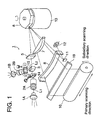
- Fig. 1 is a view of a comprehensive structure showing an example of a two-beam optical scanning unit.
- numerals 1A and 1B represent semiconductor laser beam emitting bodies.
- Numerals 2A and 2B are collimator lenses (an optical system for beam shaping).
- Numerals 14 and 15 are prisms for the primary and subsidiary scanning adjustment.
- Numeral 3 is a beam composition prism.
- Numeral 5 is the first cylindrical lens.
- Numeral 6 is a polygonal mirror, and
- numeral 7 is an f ⁇ lens.
- Numeral 8 is the second cylindrical lens, and numeral 9 is a mirror.
- Numeral 10 is a photoreceptor drum.
- Numeral 11 is a timing detection mirror, and numeral 12 is a synchronism detector.
- Numeral 13 is a driving motor for the polygonal mirror 6.
- a beam L 1 emitted from the semiconductor laser beam emitting body 1A is made parallel by the collimator lens 2A, and then enters into the beam composition prism 3.
- a beam L 2 emitted from the semiconductor laser beam emitting body 1B arranged such that it is perpendicular to the semiconductor laser beam emitting body 1A, is also made parallel in the same way as in the semiconductor laser beam emitting body 1A by the collimator lens 2B, and then, enters into the beam composition prism 3.
- the pitch of this beam emitted from the semiconductor laser beam emitting body 1B is shifted by a predetermined value from the beam, and emitted from the semiconductor laser beam emitting body 1A in the subsidiary direction.
- Both beams enter into the polygonal mirror 6 through the first cylindrical lens 5 of the first image forming optical system.
- the reflected light passes through the second image forming optical system composed of the f ⁇ lens 7 and the second cylindrical lens 8, and simultaneously scans two lines with a predetermined spot diameter on the photoreceptor drum surface 10 under the condition that the pitch of one beam is shifted by a predetermined value from that of the other beam in the subsidiary scanning direction.
- fine adjustment in the primary scanning direction is performed previously by an adjustment mechanism, which is not shown in the drawing.
- a light beam enters into the synchronism detector 12 before the start of scanning through the mirror 11.
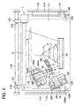
- Fig. 2 is a plan view of the two-beam optical scanning system unit 1.
- Casings 201 and 201A in which semiconductor laser emitting bodies 1A and 1B, collimator lenses 2A and 2B are respectively provided, are arranged on a base member 111 as shown in the drawing, and beams L 1 and L 2 are emitted at an angle of 90° with respect to each other.
- the casings 201 and 201A are respectively arranged onto angle changing members 125 and 125A.
- the angle changing members 125 and 125A are respectively located on parallel moving members 124 and 124A, which move in parallel in the primary scanning direction on the base member 111.
- the beam composition prism 3 and the first cylindrical lens 5 are fixed by a supporting member 123.
- the beam L 1 and L 2 are composed by the beam composition prism 3.
- the supporting member 123 is fixed onto the base member 111 so that the composed beam can enter into the polygonal mirror 6.
- both ends of the base member 111 are respectively located on the supporting members 114 and 115 provided in the image forming apparatus 113.
- the optical scanning system unit 1 is guided in the direction perpendicular to the beam scanning direction by guide members 116 and 117 respectively provided on both end positions of the base member 111, and located at a predetermined position.
- an engagement stay 118 which is used as a reference position, is provided in the image forming apparatus 113 in the same direction as the light beam scanning direction, and engaging claw members 119 and 120 are respectively provided on both end positions of the base member 111.
- These claw members are respectively engaged with groove portions 121 and 122 formed on the engagement stay 118.
- the width of one groove portion 121 is formed the same as that of the engagement claw member 119, and the width of the other groove portion is formed larger than that of the engagement claw member 120, so that the engagement operation can be smoothly carried out, and the claw members can be accurately positioned.
- positioning pins 128 and 128A are fixed so that the rear end of the base member 111 can be positioned in a predetermined position, and positioning members 129 and 129A for engaging with the positioning pins 128 and 128A, are respectively provided on the rear end of the base member 111.
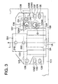
- Figs. 3 and 4 show the structure of the parallel moving member 124 and the angle changing member 125 provided on the base member 111.
- the first guiding recesses 124B and 124C formed on the parallel moving member 124 which moves in parallel in the primary scanning direction, are provided such that these recesses are engaged with guide members 132 and 133 provided on the base member 111, and the parallel moving member 124 is fixed onto the base member by fixing screws 134 and 135.
- the second cam groove 124A which is engaged with the eccentric cam 130 provided on an axis 131, is formed on the base member 111.
- the angle changing member 125 is located on the parallel moving member 124, and one end of the angle changing member 125 is rotatably provided around a shaft 138.
- the third cam groove 125A which is engaged with the eccentric cam 136 provided on the axis 137, is formed on the other end of the angle changing member 125.
- a fixing screw 139 is provided which fixes the angle changing member 125 onto the parallel moving member 124 at the position at which the angle is changed.
- a casing 201 in which the semiconductor laser beam emitting body 1A and the collimator lens 2A are provided, is fixed on the angle changing member 125 in the direction of a beam L 1 .
- Numerals 219 and 220 are screw rods for adjusting a prism 200 provided in the casing 201 (refer to Fig. 8).
- the parallel moving member 124 is moved parallely: initially, the hold by fixing screws 134 and 135 is released; the axis 131 is rotated and the eccentric cam 130 is rotated; and the parallel moving member 124 is moved in parallel in the right and left directions, shown by arrows, by the first guiding recesses 124B, 124C, and the guide members 132 and 133 provided on the base member 111, through the second cam groove 124A. Due to this movement, the casing 201 provided on the angle changing member 125 can be adjusted to move in parallel to the beam L 1 . That is, the beam L 1 from the semiconductor laser beam emitting body 1A can be adjusted in the primary scanning direction.
- the parallel moving member 124 is fixed onto the the base member 111 by fixing screws 134 and 135.
- the angle of the angle changing member 125 is changed, initially, the hold by the fixing screw 139 is released; the eccentric cam 136, provided on the axis 137, is rotated so that the parallel moving member 124 is moved; and the angle changing member 125 is adjusted to rotate around the shaft 138 in the direction shown by the arrow, through the third cam groove 125A, by the rotation of the eccentric cam 136. Due to this adjustment, the angle of the casing 201 provided on the angle changing member 125 is adjusted with respect to the beam L 1 . That is, the angle of the beam L 1 from the semiconductor laser beam emitting body 1A is adjusted.
- a worm gear G 1 and a worm G 2 are provided on the axis 131, and a worm gear G 3 and a worm G 4 are provided on the axis 137.
- a worm gear G 2 or worm G 4 are rotated, and the worm gear G 1 or worm gear G 3 is rotated, fine adjustment can be performed through eccentric cams 130 and 136.
- Fig. 5 shows a beam position detection means for adjusting beam L 1 .
- the optical member located between the polygonal mirror 6 and the photoreceptor drum 10 is removed.
- the beam position detection member S is arranged at a position at which the beam L 1 reflected from the polygonal mirror 6 is directly received, and a supporting body S 1 , on which the beam position detection member S is provided, is arranged at the measuring position outside the apparatus.
- the beam L 1 is emitted from the semiconductor laser beam emitting body 1A under the above conditions, and the beam pitches is adjusted so that it is within a predetermined specification, using the above adjustment method.
- Numeral 112 is a cover, and an opening 112A for measuring is formed in a portion of the cover 112.
- Numeral 113A is an outside board of the image forming apparatus 113 in which the opening 112A is formed.
- Fig. 6 shows a supporting member 123 on which the beam composition prism 3 and the first cylindrical lens 5 shown in Fig. 2 are fixed.
- the beam composition prism 3 and the first cylindrical lens 5 are integrally fixed on the supporting member 123.
- an adhesive agent may be applied.
- the beam composition prism 3 and the first cylindrical lens 5 may be engaged and fixed on a holding portion, as shown in the drawing, which is integrally formed with the supporting member 123.
- the supporting member 123 is fixed on the base member 111 by fixing screws 126 and 127.
- Fig. 7 shows the beam adjusting method shown in Fig. 3, and a means in which fine adjustment is carried out in the primary scanning direction and subsidiary scanning direction by a light beam compression prism 200 shown in Fig. 8.
- the first guiding recesses 124B, 124C formed on the parallel moving member 124 which is parallely moved in the primary scanning direction, are engaged with the guide members 132, 133 provided on the base member 111, and the parallel moving member 124 is fixed to the base member 111 by the fixing screws 134 and 135.
- the eccentric cam 130 is provided on the axis 131 rotated by a gear G 7 and a reduction gear G 6 .
- the second cam groove 124A, with which the eccentric cam 130 is engaged, is formed on the parallel moving member 124.
- the angle changing member 125 is located on the parallel moving member 124. One end of the angle changing member 125 is rotatably provided on the shaft 138. An axis 137 is rotated by a gear G 9 and a reduction gear G 8 . An eccentric cam 136 is provided on the axis 137.
- the third cam groove 125A with which the eccentric cam 136 is engaged, is formed on the other end of the angle changing member 125.
- a fixing screw 139 for fixing the angle changing member 125 onto the parallel moving member 124 at the position at which the angle is changed, is provided on the angle changing member 125.
- the casing 201 in which the semiconductor laser beam emitting body 1A and the collimator lens 2A are provided, is fixed on the angle changing member 125 along the direction of the beam L 1 .
- Numerals 219 and 220 are screw rods for adjusting a light beam compression prism 200 (refer to Fig. 8) provided in the casing 201.
- the parallel moving member 124 when the parallel moving member 124 is moved in parallel, initially, the hold by the fixing screws 134 and 135 is released; the axis 131 is rotated by the gear G 7 and the reduction gear G 6 ; the eccentric cam 130 is rotated; and thereby, the parallel moving member 124 is moved laterally in parallel as shown by the arrow while the first guiding recesses 124B and 124C are engaged with guide members 132 and 133, provided on the base member 111. Due to this movement, the casing 201 provided on the angle changing member 125 can be adjusted so that it moves in parallel to the beam L 1 . That is, the beam L 1 from the semiconductor laser beam emitting body 1A can be adjusted to be emitted in the primary scanning direction.
- the parallel moving member 124 is fixed onto the base member 111 by fixing screws 134 and 135.
- the hold by the fixing screw 139 is initially released; the eccentric cam 136 provided on the axis 137 is rotated by a gear G 9 and a reduction gear G 8 ; and thereby, the angle changing member 125 is rotated around the shaft 138 in the arrowed direction through the third cam groove so that its angle is adjusted.
- the angle of the casing 201 provided on the angle changing member 125 is adjusted with respect to the beam L 1 . That is, the angle of the beam L 1 from the semiconductor laser beam emitting body 1A is adjusted.
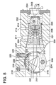
- Fig. 8 shows the casing 201 in which the semiconductor laser beam emitting body 1A, the collimator lens 2A and the beam compression prism 200 are accommodated.
- a beam transmission hole 203 is formed along the beam L 1 .
- a long hole 204 is formed along the beam L 1 so that an inner barrel 202, in which the collimator lens 2A is fixed, is mounted in the casing 201.
- a female screw thread 205 is formed in the long hole 204 so that the the inner barrel 202 can be screwed into the long hole 204.
- a male screw thread 206 is formed on the outer surface of the inner barrel 202 so that it can be screwed into the female screw thread 205, and the inner barrel 202 is fixed by screws in the long hole 204 as shown in the drawing.
- a tapered surface 207 (at approximately 30° with respect to the horizontal surface), is formed on the surface of the long hole 204 so that the tapered surface of the long hole 204 is extended around the beam L 1 in the direction from the portion of the female screw thread 205 to the left in the drawing.
- a tapered surface 208 is formed on the outer surface of the inner barrel 202 with the same angle as that of the tapered surface 207.
- the angle ⁇ of the slits is formed at approximately 60°.
- Numeral 210 is a rotation assembling hole formed at a plurality of portions formed between slits 209. The rotation assembling hole 210 is formed such that it can coincide with an assembling operation long hole 211 formed on the casing 201 at the final assembling position.
- Numeral 215 is a hole for an adhesive agent 214 and is formed in the casing 201.
- the beam compression prism 200 is attached to a beam compression prism attaching member 216 at a predetermined angle.
- the beam compression prism attaching member 216 is fixed to a cylindrical frame 217.
- the cylindrical frame 217 is rotatably attached to the beam compression prism attaching portion 218, formed along the long hole 204 in the casing, in the direction crossing the light beam L 1 .
- Screw rods 219 and 220 which are screwed into the casing 201, are arranged at a portion of the cylindrical frame 217 symmetrically to each other with respect to a vertical center line of the cylindrical frame in the drawing.
- a tip of the screw rod 219 directly touches a step portion 221 formed on the cylindrical frame 217.
- a tip of the screw rod 220 touches a step portion formed on the cylindrical frame 217 through a spring member 222.
- the cylindrical frame 217 is fixed to the casing 201 by a screw rod 226 through a side plate 224.
- the screw rod 226 for fixing is loosened, and then, the screw rod 219 is rotated for adjusting.
- the step portion 221 formed on a portion of the cylindrical frame 217 is always contacted by the tip of the screw rod 219 through the force of spring member 222.
- the light beam compression prism 200 is rotated for adjusting the transmitting direction through the cylindrical frame 217 and the beam compression prism attaching member 216, while the width of the beam L 1 is reduced to a predetermined value.
- the cylindrical frame 217 is fixed by the screw rod 226 in the casing 201. In this case, even when the screw rod 226 for fixing is rotated clockwise, the tip of the screw rod 219 is always blocked by the step portion 221 formed on the cylindrical frame 217, and the light beam compression prism 200 is not moved from the adjusted position.
- the same beam compression prism as the above-described prism 200 is also provided in the casing 201, and the primary scanning direction and the subsidiary scanning direction of luminous flux of the beam L 1 emitted from the semiconductor laser beam emitting body 1A, and the beam L 2 emitted from the semiconductor laser beam emitting body 1B, are finely adjusted.
- the adjusting means for precisely adjusting each beam position of the primary scanning direction and the subsidiary scanning direction, and further, the fine adjusting means for precisely adjusting the rotation, are provided in the unit. Accordingly, the beam position adjustment of the primary scanning direction and the subsidiary scanning direction can be separately and accurately carried out by easy adjustments, which is greatly advantageous.
Description
- In a conventional image forming apparatus, a recording operation is performed by writing to a photoreceptor with a laser beam; therefore, the image forming apparatus consists of a semiconductor laser emitting body to generate a laser beam and a collimator lens or the like, which are formed in a single unit for an optical scanning system in an exposure unit. When a recording operation by writing with two beams is performed, two sets of the units, in each of which the semiconductor laser emitting body and the collimator lens or the like are unitedly formed, are provided.
- However, in this case, the optical scanning paths of the two beams need to be arranged precisely. Conventionally, a precise adjustment of the optical scanning paths in the subsidiary scanning direction is, for example, disclosed as the way that the pitch adjustment in the subsidiary scanning direction is performed with one prism (Japanese Patent Publication Open to the Public Inspection Nos. JP-A-58 68016 (1983), and JP-A-63 50809 (1988) and as the way that the adjustment is performed by moving the single unit, consists of the semiconductor laser unit, in the subsidiary scanning direction (Japanese Patent Publication Open to the Public Inspection No. JP-A-62 86324 (1987).
- As explained above, in the conventional technologies, the adjustment of the optical scanning paths in the subsidiary scanning direction is performed. Further, there is a conventional way that a discrepancy in the primary scanning direction is adjusted by detecting the discrepancy of the two beams with an index sensor and delaying the signals electrically. However, when the discrepancy of the two beams is large, it is impossible to compensate the discrepancy completely. In other words, if the incident position of one of the two beams is discrepant in the primary scanning direction in relation to the another one of the two beams, the scanning focal positions of the two beams are discrepant from each other.
- When the two beams, generated from two semiconductor laser emitting bodies, are composed by a beam composition prism, if the location error of the beam composition prism occurs, there tends to be a problem that the beam at the reflection side of the beam composition prism has the discrepancy of its axis. For example, when the beam composition prism is positioned discrepant in a plane parallel to the axis of the beams, one beam, which is penetrate the beam composition prism, is not effected but the another beam, which is reflected at the beam composition prism, is effected so that the irradiating direction of the beam becomes discrepant in the primary scanning direction. Especially, when the beam composition prism is fixed to a part of the optical scanning system with an adhesive, the precision of the beam arrangements is required to be very strict; therefore, when a adhesion mistake occurs or a shape precision at the adhesion surface is not ensured, the whole unit of the optical scanning system can be defective by the cause of the discrepancy of the beam axis. Further, the adhesion is not suitable for the easy assembly. It causes a complicated inspection for the entire exposure unit after the adhesion.
- DE-A-3726375 describes an image forming apparatus having a two beam optical scanning apparatus comprising a pair of semi-conductor laser beam omitting means each generating a respect laser beam so that two laser beams are generated.
- EP-A-0420124 discloses an optical unit for use in a laser beam printer in which a laser beam generated by a laser diode is converted by a group of conversion lenses into a laser beam having a predetermined size cross section.
- JP-A-58068016 discloses a scanning optical system capable of changing scanning line pitch having a movable prism for adjusting the emitting direction of a laser beam.
- Accordingly, the objective of the present invention is to solve the above explained problems and to prevent the recording apparatus, which write with two beams, for the positioning discrepancy of two scanning beams, especially in the primary scanning direction.
- In order to accomplish the above-described objects, the present invention provides the following apparatus.
- An image forming apparatus having a two-beam optical scanning apparatus comprising:
- a pair of semiconductor laser beam emitting means each for generating a respect laser beam so that two laser beams are generated;
- a beam composition prism for composing said two laser beams;
- a photoreceptor for holding an image written with said two laser beams;
- a deflector for deflecting said two laser beams onto said photoreceptor in a primary scanning direction so that said two laser beams are emitted on a primary scanning plane; characterized in that said image forming apparatus further comprises two supporting means each for respectively supporting one of said pair of semiconductor laser beam emitting means; and
- a moving means for moving at least one of said two supporting means so that at least one of said two laser beams is adjusted to have a predetermined emitting direction; wherein said moving means includes an angle changing member for changing an angle of a beam path of said respect laser beam.
-
- In the apparatus of the invention preferably said moving means moves at least one of said two supporting means in a direction parallel to said primary scanning direction of said two laser beams.
- Preferably said moving means of the apparatus of the invention moves an angle of at least one of said two supporting means on said primary scanning plane.
- Further in an apparatus according to the invention there is also provided a beam compression prism placed between at least one of said pair of semiconductor laser beam omitting means as said beam composition prism, for adjusting an emitting direction of at least one of said two laser beams; and the apparatus further comprises a moving means for rotating said beam compression prism on said primary scanning plane so that at least one of said two beams is shifted in said primary scanning direction.
- In a preferred embodiment of the apparatus of the invention there is provided a supporting means for supporting said beam composition prism, wherein said beam composition prism supporting means is moveable configured in said apparatus so that said beam composition prism supporting means is capable of moving in a direction parallel to said primary scanning plane.
- In the apparatus of the preferred embodiment of the invention, it is further preferred that said beam composition prism supporting means is capable of moving in a direction parallel to one of said two laser beams which is omitted from of said pair of semi-conductor laser beam emitting means.
- Also in said preferred embodiment of the apparatus of the invention, there is provided a cylindrical lens placed between said beam composition prism and said deflector; wherein said cylindrical lens is uniformly configured with said beam composition prism supporting means so that said cylindrical lens is capable of uniformly moving with said beam composition prism.
- In an apparatus of the present invention wherein said moving means moves at least one of said two supporting means in a direction parallel to said primary scanning direction of said two laser beams, it is preferred that said moving means includes an eccentric cam for moving at least one of said two supporting means.
- In an apparatus of the present invention wherein said moving means moves an angle of at least one of said two supporting means on said primary scanning plane, it is preferred that said moving means includes an eccentric cam for moving said angle of at least one of said two supporting means and a worm gear for rotating said eccentric cam.
- In an apparatus of the present invention it is preferred that there is an adjusting hole provided on an outer body of said apparatus for allowing said two laser beams emitted to a beam position detection means provided outside said apparatus, so that at least one of said two laser beams is adjusted to have a predetermined emitting direction.
-
- Fig.1 is a perspective view showing the overall structure of a two-beam optical scanning unit of the present invention.
- Fig. 2 is a plan view showing the overall structure of the two-beam optical scanning unit of the present invention.
- Fig. 3 is a plan view showing an adjusting unit of a light beam generating apparatus of the present invention.
- Fig. 4 is a perspective view showing the adjusting unit of the light beam generating apparatus of the present invention.
- Fig. 5 is a view showing the structure of a light beam adjustment detecting apparatus of the present invention.
- Fig. 6 is a perspective view showing a beam composition prism and a cylindrical lens of the present invention.
- Fig. 7 is a plan view showing the adjusting unit of the light beam generating apparatus of the present invention.
- Fig. 8 is a vertical sectional view of a casing of the present invention, in which a beam emitting portion and a optical system are accommodated.
-
- Examples will be explained below according to the attached drawings of a two-beam optical scanning system unit of the present invention.
- Fig. 1 is a view of a comprehensive structure showing an example of a two-beam optical scanning unit.
- In Fig. 1,
numerals Numerals Numerals Numeral 3 is a beam composition prism. Numeral 5 is the first cylindrical lens. Numeral 6 is a polygonal mirror, andnumeral 7 is an f lens. Numeral 8 is the second cylindrical lens, andnumeral 9 is a mirror.Numeral 10 is a photoreceptor drum. Numeral 11 is a timing detection mirror, andnumeral 12 is a synchronism detector. Numeral 13 is a driving motor for thepolygonal mirror 6. A beam L1 emitted from the semiconductor laserbeam emitting body 1A is made parallel by thecollimator lens 2A, and then enters into thebeam composition prism 3. A beam L2 emitted from the semiconductor laserbeam emitting body 1B, arranged such that it is perpendicular to the semiconductor laserbeam emitting body 1A, is also made parallel in the same way as in the semiconductor laserbeam emitting body 1A by thecollimator lens 2B, and then, enters into thebeam composition prism 3. The pitch of this beam emitted from the semiconductor laserbeam emitting body 1B is shifted by a predetermined value from the beam, and emitted from the semiconductor laserbeam emitting body 1A in the subsidiary direction. Both beams enter into thepolygonal mirror 6 through the firstcylindrical lens 5 of the first image forming optical system. The reflected light passes through the second image forming optical system composed of the flens 7 and the secondcylindrical lens 8, and simultaneously scans two lines with a predetermined spot diameter on thephotoreceptor drum surface 10 under the condition that the pitch of one beam is shifted by a predetermined value from that of the other beam in the subsidiary scanning direction. In this connection, fine adjustment in the primary scanning direction is performed previously by an adjustment mechanism, which is not shown in the drawing. - In order to detect the synchronism of each line, a light beam enters into the
synchronism detector 12 before the start of scanning through the mirror 11. - Fig. 2 is a plan view of the two-beam optical
scanning system unit 1.Casings laser emitting bodies collimator lenses base member 111 as shown in the drawing, and beams L1 and L2 are emitted at an angle of 90° with respect to each other. Thecasings angle changing members angle changing members members base member 111. Further, thebeam composition prism 3 and the firstcylindrical lens 5 are fixed by a supportingmember 123. The beam L1 and L2 are composed by thebeam composition prism 3. The supportingmember 123 is fixed onto thebase member 111 so that the composed beam can enter into thepolygonal mirror 6. In the opticalscanning system unit 1, as shown in Fig. 2, both ends of thebase member 111 are respectively located on the supportingmembers image forming apparatus 113. The opticalscanning system unit 1 is guided in the direction perpendicular to the beam scanning direction byguide members base member 111, and located at a predetermined position. Further, in the front position toward which the opticalscanning system unit 1 is guided, anengagement stay 118, which is used as a reference position, is provided in theimage forming apparatus 113 in the same direction as the light beam scanning direction, and engagingclaw members base member 111. These claw members are respectively engaged withgroove portions engagement stay 118. In thegroove portions groove portion 121 is formed the same as that of theengagement claw member 119, and the width of the other groove portion is formed larger than that of theengagement claw member 120, so that the engagement operation can be smoothly carried out, and the claw members can be accurately positioned. Further, positioning pins 128 and 128A are fixed so that the rear end of thebase member 111 can be positioned in a predetermined position, andpositioning members base member 111. - Figs. 3 and 4 show the structure of the parallel moving
member 124 and theangle changing member 125 provided on thebase member 111. As shown in Fig. 3, the first guiding recesses 124B and 124C, formed on the parallel movingmember 124 which moves in parallel in the primary scanning direction, are provided such that these recesses are engaged withguide members base member 111, and the parallel movingmember 124 is fixed onto the base member by fixingscrews second cam groove 124A, which is engaged with theeccentric cam 130 provided on anaxis 131, is formed on thebase member 111. Further, theangle changing member 125 is located on the parallel movingmember 124, and one end of theangle changing member 125 is rotatably provided around ashaft 138. Thethird cam groove 125A, which is engaged with theeccentric cam 136 provided on theaxis 137, is formed on the other end of theangle changing member 125. A fixingscrew 139 is provided which fixes theangle changing member 125 onto the parallel movingmember 124 at the position at which the angle is changed. Acasing 201, in which the semiconductor laserbeam emitting body 1A and thecollimator lens 2A are provided, is fixed on theangle changing member 125 in the direction of a beam L1. Numerals 219 and 220 are screw rods for adjusting aprism 200 provided in the casing 201 (refer to Fig. 8). - Due to the above structure, the following operations are carried out when the parallel moving
member 124 is moved parallely: initially, the hold by fixingscrews axis 131 is rotated and theeccentric cam 130 is rotated; and the parallel movingmember 124 is moved in parallel in the right and left directions, shown by arrows, by the first guiding recesses 124B, 124C, and theguide members base member 111, through thesecond cam groove 124A. Due to this movement, thecasing 201 provided on theangle changing member 125 can be adjusted to move in parallel to the beam L1. That is, the beam L1 from the semiconductor laserbeam emitting body 1A can be adjusted in the primary scanning direction. After adjustment has been completed, the parallel movingmember 124 is fixed onto the thebase member 111 by fixingscrews angle changing member 125 is changed, initially, the hold by the fixingscrew 139 is released; theeccentric cam 136, provided on theaxis 137, is rotated so that the parallel movingmember 124 is moved; and theangle changing member 125 is adjusted to rotate around theshaft 138 in the direction shown by the arrow, through thethird cam groove 125A, by the rotation of theeccentric cam 136. Due to this adjustment, the angle of thecasing 201 provided on theangle changing member 125 is adjusted with respect to the beam L1. That is, the angle of the beam L1 from the semiconductor laserbeam emitting body 1A is adjusted. - In Fig. 4, as a rotation means of the
axes axis 131, and a worm gear G3 and a worm G4 are provided on theaxis 137. When the worm G2 or worm G4 are rotated, and the worm gear G1 or worm gear G3 is rotated, fine adjustment can be performed througheccentric cams - Fig. 5 shows a beam position detection means for adjusting beam L1. Initially, as shown in the drawing, the optical member located between the
polygonal mirror 6 and thephotoreceptor drum 10 is removed. The beam position detection member S is arranged at a position at which the beam L1 reflected from thepolygonal mirror 6 is directly received, and a supporting body S1, on which the beam position detection member S is provided, is arranged at the measuring position outside the apparatus. The beam L1 is emitted from the semiconductor laserbeam emitting body 1A under the above conditions, and the beam pitches is adjusted so that it is within a predetermined specification, using the above adjustment method. This adjustment is simultaneously carried out on the beam L2 emitted from the laserbeam emitting body 1B, and the beam adjustment in the primary and the secondary scanning directions can be carried out.Numeral 112 is a cover, and anopening 112A for measuring is formed in a portion of thecover 112.Numeral 113A is an outside board of theimage forming apparatus 113 in which theopening 112A is formed. - Fig. 6 shows a supporting
member 123 on which thebeam composition prism 3 and the firstcylindrical lens 5 shown in Fig. 2 are fixed. Thebeam composition prism 3 and the firstcylindrical lens 5 are integrally fixed on the supportingmember 123. As a fixing method, an adhesive agent may be applied. Alternatively, thebeam composition prism 3 and the firstcylindrical lens 5 may be engaged and fixed on a holding portion, as shown in the drawing, which is integrally formed with the supportingmember 123. The supportingmember 123 is fixed on thebase member 111 by fixingscrews - Fig. 7 shows the beam adjusting method shown in Fig. 3, and a means in which fine adjustment is carried out in the primary scanning direction and subsidiary scanning direction by a light
beam compression prism 200 shown in Fig. 8. Initially, in Fig. 7, as also shown in Fig. 3, the first guiding recesses 124B, 124C formed on the parallel movingmember 124, which is parallely moved in the primary scanning direction, are engaged with theguide members base member 111, and the parallel movingmember 124 is fixed to thebase member 111 by the fixingscrews eccentric cam 130 is provided on theaxis 131 rotated by a gear G7 and a reduction gear G6. Thesecond cam groove 124A, with which theeccentric cam 130 is engaged, is formed on the parallel movingmember 124. Theangle changing member 125 is located on the parallel movingmember 124. One end of theangle changing member 125 is rotatably provided on theshaft 138. Anaxis 137 is rotated by a gear G9 and a reduction gear G8. Aneccentric cam 136 is provided on theaxis 137. Thethird cam groove 125A with which theeccentric cam 136 is engaged, is formed on the other end of theangle changing member 125. A fixingscrew 139 for fixing theangle changing member 125 onto the parallel movingmember 124 at the position at which the angle is changed, is provided on theangle changing member 125. Further, thecasing 201, in which the semiconductor laserbeam emitting body 1A and thecollimator lens 2A are provided, is fixed on theangle changing member 125 along the direction of the beam L1. Numerals 219 and 220 are screw rods for adjusting a light beam compression prism 200 (refer to Fig. 8) provided in thecasing 201. - By the structure described above, when the parallel moving
member 124 is moved in parallel, initially, the hold by the fixingscrews axis 131 is rotated by the gear G7 and the reduction gear G6; theeccentric cam 130 is rotated; and thereby, the parallel movingmember 124 is moved laterally in parallel as shown by the arrow while the first guiding recesses 124B and 124C are engaged withguide members base member 111. Due to this movement, thecasing 201 provided on theangle changing member 125 can be adjusted so that it moves in parallel to the beam L1. That is, the beam L1 from the semiconductor laserbeam emitting body 1A can be adjusted to be emitted in the primary scanning direction. After adjustment has been completed, the parallel movingmember 124 is fixed onto thebase member 111 by fixingscrews angle changing member 125 is changed, the hold by the fixingscrew 139 is initially released; theeccentric cam 136 provided on theaxis 137 is rotated by a gear G9 and a reduction gear G8; and thereby, theangle changing member 125 is rotated around theshaft 138 in the arrowed direction through the third cam groove so that its angle is adjusted. By this rotation and adjustment, the angle of thecasing 201 provided on theangle changing member 125 is adjusted with respect to the beam L1. That is, the angle of the beam L1 from the semiconductor laserbeam emitting body 1A is adjusted. - Fig. 8 shows the
casing 201 in which the semiconductor laserbeam emitting body 1A, thecollimator lens 2A and thebeam compression prism 200 are accommodated. Inside thecasing 201, abeam transmission hole 203 is formed along the beam L1. Along hole 204 is formed along the beam L1 so that aninner barrel 202, in which thecollimator lens 2A is fixed, is mounted in thecasing 201. Afemale screw thread 205 is formed in thelong hole 204 so that the theinner barrel 202 can be screwed into thelong hole 204. On the other hand, amale screw thread 206 is formed on the outer surface of theinner barrel 202 so that it can be screwed into thefemale screw thread 205, and theinner barrel 202 is fixed by screws in thelong hole 204 as shown in the drawing. Atapered surface 207, (at approximately 30° with respect to the horizontal surface), is formed on the surface of thelong hole 204 so that the tapered surface of thelong hole 204 is extended around the beam L1 in the direction from the portion of thefemale screw thread 205 to the left in the drawing. Atapered surface 208 is formed on the outer surface of theinner barrel 202 with the same angle as that of the taperedsurface 207. A plurality ofslits 209, which penetrate the taperedsurface 208 to thetransmission hole 203 of the beam L1, are formed on the portion on which the taperedsurface 208 is formed. The angle of the slits is formed at approximately 60°.Numeral 210 is a rotation assembling hole formed at a plurality of portions formed betweenslits 209. Therotation assembling hole 210 is formed such that it can coincide with an assembling operationlong hole 211 formed on thecasing 201 at the final assembling position.Numeral 215 is a hole for anadhesive agent 214 and is formed in thecasing 201. - The
beam compression prism 200 is attached to a beam compressionprism attaching member 216 at a predetermined angle. The beam compressionprism attaching member 216 is fixed to acylindrical frame 217. Thecylindrical frame 217 is rotatably attached to the beam compressionprism attaching portion 218, formed along thelong hole 204 in the casing, in the direction crossing the light beam L1. Screw rods 219 and 220, which are screwed into thecasing 201, are arranged at a portion of thecylindrical frame 217 symmetrically to each other with respect to a vertical center line of the cylindrical frame in the drawing. A tip of thescrew rod 219 directly touches astep portion 221 formed on thecylindrical frame 217. A tip of thescrew rod 220 touches a step portion formed on thecylindrical frame 217 through aspring member 222. Thecylindrical frame 217 is fixed to thecasing 201 by ascrew rod 226 through aside plate 224. - In the
beam compression prism 200 structured as described above, initially, thescrew rod 226 for fixing is loosened, and then, thescrew rod 219 is rotated for adjusting. At this time, thestep portion 221 formed on a portion of thecylindrical frame 217 is always contacted by the tip of thescrew rod 219 through the force ofspring member 222. When thescrew rod 219 is rotated for adjusting, the lightbeam compression prism 200 is rotated for adjusting the transmitting direction through thecylindrical frame 217 and the beam compressionprism attaching member 216, while the width of the beam L1 is reduced to a predetermined value. After the adjustment is completed, thecylindrical frame 217 is fixed by thescrew rod 226 in thecasing 201. In this case, even when thescrew rod 226 for fixing is rotated clockwise, the tip of thescrew rod 219 is always blocked by thestep portion 221 formed on thecylindrical frame 217, and the lightbeam compression prism 200 is not moved from the adjusted position. - The same beam compression prism as the above-described
prism 200 is also provided in thecasing 201, and the primary scanning direction and the subsidiary scanning direction of luminous flux of the beam L1 emitted from the semiconductor laserbeam emitting body 1A, and the beam L2 emitted from the semiconductor laserbeam emitting body 1B, are finely adjusted. - As described above, according to the two-beam optical scanning unit of the present invention, the adjusting means for precisely adjusting each beam position of the primary scanning direction and the subsidiary scanning direction, and further, the fine adjusting means for precisely adjusting the rotation, are provided in the unit. Accordingly, the beam position adjustment of the primary scanning direction and the subsidiary scanning direction can be separately and accurately carried out by easy adjustments, which is greatly advantageous.
Claims (10)
- An image forming apparatus having a two-beam optical scanning apparatus (1) comprising:characterized in that said image forming apparatus (1) further comprises two supporting means (201,201A) each for respectively supporting one of said pair of semiconductor laser beam emitting means (1A,1B); anda pair of semiconductor laser beam emitting means (1A,1B) each for generating a respect laser beam so that two laser beams (L1,L2) are generated;a beam composition prism (3) for composing said two laser beams (L1,L2);a photoreceptor (10) for holding an image written with said two laser beams (L1,L2);a deflector (6) for deflecting said two laser beams (L1,L2) onto said photoreceptor in a primary scanning direction so that said two laser beams (L1,L2) are emitted on a primary scanning plane;
a moving means (124,124A) for moving at least one of said two supporting means (201,201A) so that at least one of said two laser beams (L1, L2) is adjusted to have a predetermined emitting direction;
wherein said moving means (124,124A) includes an angle changing member (125,125A) for changing an angle of a beam path of said respect laser beam (L1,L2). - The apparatus (1) of claim 1, wherein said moving means (124,124A) moves at least one of said two supporting means (201,201A) in a direction parallel to said primary scanning direction of said two laser beams (L1,L2).
- The apparatus (1) of claim 1, wherein said moving means (124,124A) moves an angle of at least one of said two supporting means (201,201A) on said primary scanning plane.
- The image forming apparatus (1) of claim 1, wherein a beam compression prism (14,15) is placed between at least one of said pair of semiconductor laser beam emitting means (1A,1B) and said beam composition prism (3), for adjusting an emitting direction of at least one of said two laser beams (L1,L2);
and further comprising a moving means for rotating said beam compression prism (14,15) on said primary scanning plane so that at least one of said two beams (L1,L2) is shifted in said primary scanning direction. - The image forming apparatus (1) of claim 1 further comprising a supporting means (123) for supporting said beam composition prism (3);
wherein said beam composition prism supporting means (123) is movably configured in said apparatus so that said beam composition prism supporting means (123) is capable of moving in a direction parallel to said primary scanning plane. - The apparatus (1) of claim 5, wherein said beam composition prism supporting means (123) is capable of moving in a direction parallel to one of said two laser beams (L1,L2) which is emitted from one of said pair of semiconductor laser beam emitting means (1A,1B).
- The apparatus (1) of claim 5, further comprising a cylindrical lens (5) placed between said beam composition prism (3) and said deflector (6);
wherein said cylindrical lens (5) is uniformly configured with said beam composition prism supporting means so that said cylindrical lens (5) is capable of uniformly moving with said beam composition prism (3). - The apparatus (1) of claim 2, wherein said moving means (124,124A) includes an eccentric cam (130,136) for moving at least one of said two supporting means (124,124A).
- The apparatus (1) of claim 3, wherein said moving means (124,124A) includes:an eccentric cam (130,136) for moving said angle of at least one of said two supporting means (124,124A); anda worm gear (61,62) for rotating said eccentric cam (130,136).
- The apparatus (1) of claim 1, further comprising:an adjusting hole (112A) provided on an outer body (201) of said apparatus (1) for allowing said two laser beams emitted to a beam position detection means (S), provided outside said apparatus (1), so that at least one of said two laser beams (L1,L2) is adjusted to have a predetermined emitting direction.
Applications Claiming Priority (3)
| Application Number | Priority Date | Filing Date | Title |
|---|---|---|---|
| JP20379994 | 1994-08-29 | ||
| JP20379994A JP3538651B2 (en) | 1994-08-29 | 1994-08-29 | Image forming apparatus having two-beam optical scanning device |
| JP203799/94 | 1994-08-29 |
Publications (3)
| Publication Number | Publication Date |
|---|---|
| EP0703088A2 EP0703088A2 (en) | 1996-03-27 |
| EP0703088A3 EP0703088A3 (en) | 1998-01-28 |
| EP0703088B1 true EP0703088B1 (en) | 2002-04-17 |
Family
ID=16479938
Family Applications (1)
| Application Number | Title | Priority Date | Filing Date |
|---|---|---|---|
| EP95305952A Expired - Lifetime EP0703088B1 (en) | 1994-08-29 | 1995-08-25 | Image forming apparatus having a two-beam optical scanning unit |
Country Status (3)
| Country | Link |
|---|---|
| US (1) | US5771061A (en) |
| EP (1) | EP0703088B1 (en) |
| JP (1) | JP3538651B2 (en) |
Families Citing this family (21)
| Publication number | Priority date | Publication date | Assignee | Title |
|---|---|---|---|---|
| JP3666077B2 (en) * | 1995-09-12 | 2005-06-29 | コニカミノルタホールディングス株式会社 | Image forming apparatus and manufacturing method thereof |
| JP3298042B2 (en) * | 1995-09-14 | 2002-07-02 | コニカ株式会社 | Image forming apparatus and control method of image forming apparatus |
| JP3209690B2 (en) * | 1996-11-15 | 2001-09-17 | 株式会社東芝 | Beam light scanning device and image forming apparatus |
| JP3222052B2 (en) * | 1996-01-11 | 2001-10-22 | 株式会社東芝 | Optical scanning device |
| US6400442B1 (en) | 1996-08-28 | 2002-06-04 | Polaroid Corporation | Optical system for use in a photographic printer |
| US6011577A (en) * | 1997-06-30 | 2000-01-04 | Polaroid Corporation | Modular optical print head assembly |
| US5946023A (en) * | 1998-05-13 | 1999-08-31 | Eastman Kodak Company | Mount for beam shaping optics in a laser scanner |
| JP2000147398A (en) * | 1998-11-13 | 2000-05-26 | Toshiba Corp | Exposure device, and image forming device including the same |
| DE10014826A1 (en) * | 2000-03-24 | 2001-09-27 | Vitalij Lissotschenko | Scanning device for laser printer with scanning of second beam at same time or shortly before first beam at same location or nearby for higher resolution |
| JP3824528B2 (en) * | 2001-12-14 | 2006-09-20 | 株式会社リコー | Multi-beam scanning optical system and image forming apparatus |
| KR100452852B1 (en) * | 2002-01-09 | 2004-10-14 | 삼성전자주식회사 | imaging optical system and image forming apparatus having the same |
| US7151556B2 (en) | 2002-08-23 | 2006-12-19 | Samsung Electronics Co., Ltd. | Sub-scanning interval adjusting apparatus for multi-beam scanning unit |
| KR100452854B1 (en) * | 2002-08-23 | 2004-10-14 | 삼성전자주식회사 | Apparatus for adjusting a distance between beams of multi-beam laser scanning unit |
| US7151557B2 (en) * | 2004-03-19 | 2006-12-19 | Lexmark International, Inc. | Collimation assembly for adjusting laser light sources in a multi-beamed laser scanning unit |
| JP2006178324A (en) * | 2004-12-24 | 2006-07-06 | Toshiba Corp | Optical component holding device and optical component holding method |
| US20060209171A1 (en) * | 2005-03-15 | 2006-09-21 | Kabushiki Kaisha Toshiba | Optical beam scanning device and image forming apparatus |
| JP5063012B2 (en) | 2006-02-27 | 2012-10-31 | キヤノン株式会社 | Optical scanning apparatus and image forming apparatus |
| JP5009557B2 (en) | 2006-06-21 | 2012-08-22 | 株式会社リコー | Optical scanning device and image forming apparatus having the same |
| JP4501999B2 (en) * | 2007-12-17 | 2010-07-14 | コニカミノルタホールディングス株式会社 | Image forming apparatus |
| KR20140112230A (en) * | 2013-03-13 | 2014-09-23 | 삼성전자주식회사 | Method of detecting inhomogeneity of a layer and apparatus for performing the same |
| JP2017223893A (en) | 2016-06-17 | 2017-12-21 | 株式会社リコー | Optical device, optical unit, display device, and prism fixation method |
Family Cites Families (13)
| Publication number | Priority date | Publication date | Assignee | Title |
|---|---|---|---|---|
| JPS5868016A (en) * | 1981-10-20 | 1983-04-22 | Canon Inc | Scanning optical system capable of changing scanning line pitch |
| JPS58173711A (en) * | 1982-04-07 | 1983-10-12 | Hitachi Ltd | Scanning optical system by semiconductor laser beam |
| JPH0694215B2 (en) * | 1985-04-24 | 1994-11-24 | 株式会社日立製作所 | Laser printer device and scanning method thereof |
| JPS6286324A (en) * | 1985-10-11 | 1987-04-20 | Ricoh Co Ltd | Two-beam laser printer |
| JPH0682172B2 (en) * | 1985-11-20 | 1994-10-19 | 株式会社リコー | Light source device for 2-beam scanning system |
| JPS6341821A (en) * | 1986-08-08 | 1988-02-23 | Hitachi Ltd | Synthesizing device for optical beam |
| JPS6350809A (en) * | 1986-08-21 | 1988-03-03 | Ricoh Co Ltd | Optical writer |
| JPS6475239A (en) * | 1987-09-18 | 1989-03-20 | Toshiba Corp | Optical device for imaging device |
| JP2676518B2 (en) * | 1988-01-12 | 1997-11-17 | キヤノン株式会社 | Scanning optical device |
| KR910009142B1 (en) * | 1988-08-12 | 1991-10-31 | 가부시기가이샤 히다찌세이사꾸쇼 | Optical scanner |
| US5289001A (en) * | 1989-08-07 | 1994-02-22 | Hitachi, Ltd. | Laser beam scanning apparatus having a variable focal distance device and the variable focal distance device for use in the apparatus |
| JPH03116112A (en) * | 1989-09-29 | 1991-05-17 | Toshiba Corp | Scanning type optical device |
| US5296958A (en) * | 1992-05-29 | 1994-03-22 | Eastman Kodak Company | Multiple wavelength laser beam scanning system |
-
1994
- 1994-08-29 JP JP20379994A patent/JP3538651B2/en not_active Expired - Fee Related
-
1995
- 1995-08-24 US US08/518,779 patent/US5771061A/en not_active Expired - Lifetime
- 1995-08-25 EP EP95305952A patent/EP0703088B1/en not_active Expired - Lifetime
Also Published As
| Publication number | Publication date |
|---|---|
| JPH0868956A (en) | 1996-03-12 |
| US5771061A (en) | 1998-06-23 |
| EP0703088A2 (en) | 1996-03-27 |
| EP0703088A3 (en) | 1998-01-28 |
| JP3538651B2 (en) | 2004-06-14 |
Similar Documents
| Publication | Publication Date | Title |
|---|---|---|
| EP0703088B1 (en) | Image forming apparatus having a two-beam optical scanning unit | |
| EP0638830B1 (en) | Optical scanning device | |
| EP0469856B1 (en) | Viewing and illuminating video probe | |
| CN1117140A (en) | Scanning optical apparatus | |
| US6191803B1 (en) | Multiple light beam scanning optical system | |
| EP0558735B1 (en) | Adjustable mount for cylindrical lens with independent rotational feature | |
| US5757535A (en) | Optical scanner | |
| JP2696364B2 (en) | Monitor mechanism of scanning optical device | |
| US6166376A (en) | Multi-beam scanning device | |
| US5952650A (en) | Scanning optical device having a movable compound optical system | |
| US4894670A (en) | Slit projection apparatus | |
| US5839007A (en) | Internal indicator of a view finder in a camera | |
| JPH02150399A (en) | Image drawn surface control mechanism of scanning type image drawing device | |
| JPH1010448A (en) | Optical scanner | |
| JPH06331913A (en) | Two-beam optical scanner | |
| JP2659137B2 (en) | Laser light scanning device | |
| JPH0610919U (en) | Optical scanning unit | |
| JPH0869161A (en) | Image forming device with laser beam emitting means | |
| JPH04251814A (en) | Raster scanner | |
| JP2000267032A (en) | Light source device | |
| JP2001281588A (en) | Emission position adjustment structure for plane- parallel plane | |
| JPH10171974A (en) | Pattern reader | |
| JPH01191813A (en) | Light source device | |
| KR100580201B1 (en) | Mirror positioning apparatus of laser scanning unit | |
| JPH04307511A (en) | Optical writing unit |
Legal Events
| Date | Code | Title | Description |
|---|---|---|---|
| PUAI | Public reference made under article 153(3) epc to a published international application that has entered the european phase |
Free format text: ORIGINAL CODE: 0009012 |
|
| AK | Designated contracting states |
Kind code of ref document: A2 Designated state(s): GB |
|
| 17P | Request for examination filed |
Effective date: 19960222 |
|
| PUAL | Search report despatched |
Free format text: ORIGINAL CODE: 0009013 |
|
| RHK1 | Main classification (correction) |
Ipc: G02B 26/12 |
|
| AK | Designated contracting states |
Kind code of ref document: A3 Designated state(s): DE FR GB IT NL |
|
| 17Q | First examination report despatched |
Effective date: 20000502 |
|
| GRAG | Despatch of communication of intention to grant |
Free format text: ORIGINAL CODE: EPIDOS AGRA |
|
| GRAG | Despatch of communication of intention to grant |
Free format text: ORIGINAL CODE: EPIDOS AGRA |
|
| GRAH | Despatch of communication of intention to grant a patent |
Free format text: ORIGINAL CODE: EPIDOS IGRA |
|
| RBV | Designated contracting states (corrected) |
Designated state(s): GB |
|
| REG | Reference to a national code |
Ref country code: GB Ref legal event code: IF02 |
|
| GRAH | Despatch of communication of intention to grant a patent |
Free format text: ORIGINAL CODE: EPIDOS IGRA |
|
| REG | Reference to a national code |
Ref country code: DE Ref legal event code: 8566 |
|
| GRAA | (expected) grant |
Free format text: ORIGINAL CODE: 0009210 |
|
| AK | Designated contracting states |
Kind code of ref document: B1 Designated state(s): GB |
|
| PLBE | No opposition filed within time limit |
Free format text: ORIGINAL CODE: 0009261 |
|
| STAA | Information on the status of an ep patent application or granted ep patent |
Free format text: STATUS: NO OPPOSITION FILED WITHIN TIME LIMIT |
|
| 26N | No opposition filed |
Effective date: 20030120 |
|
| PGFP | Annual fee paid to national office [announced via postgrant information from national office to epo] |
Ref country code: GB Payment date: 20130821 Year of fee payment: 19 |
|
| GBPC | Gb: european patent ceased through non-payment of renewal fee |
Effective date: 20140825 |
|
| PG25 | Lapsed in a contracting state [announced via postgrant information from national office to epo] |
Ref country code: GB Free format text: LAPSE BECAUSE OF NON-PAYMENT OF DUE FEES Effective date: 20140825 |