EP0702972A1 - Safety shield having spring tether - Google Patents
Safety shield having spring tether Download PDFInfo
- Publication number
- EP0702972A1 EP0702972A1 EP95305147A EP95305147A EP0702972A1 EP 0702972 A1 EP0702972 A1 EP 0702972A1 EP 95305147 A EP95305147 A EP 95305147A EP 95305147 A EP95305147 A EP 95305147A EP 0702972 A1 EP0702972 A1 EP 0702972A1
- Authority
- EP
- European Patent Office
- Prior art keywords
- guard
- needle cannula
- distal
- spring
- safety shield
- Prior art date
- Legal status (The legal status is an assumption and is not a legal conclusion. Google has not performed a legal analysis and makes no representation as to the accuracy of the status listed.)
- Granted
Links
Images


Classifications
-
- A—HUMAN NECESSITIES
- A61—MEDICAL OR VETERINARY SCIENCE; HYGIENE
- A61M—DEVICES FOR INTRODUCING MEDIA INTO, OR ONTO, THE BODY; DEVICES FOR TRANSDUCING BODY MEDIA OR FOR TAKING MEDIA FROM THE BODY; DEVICES FOR PRODUCING OR ENDING SLEEP OR STUPOR
- A61M5/00—Devices for bringing media into the body in a subcutaneous, intra-vascular or intramuscular way; Accessories therefor, e.g. filling or cleaning devices, arm-rests
- A61M5/178—Syringes
- A61M5/31—Details
- A61M5/32—Needles; Details of needles pertaining to their connection with syringe or hub; Accessories for bringing the needle into, or holding the needle on, the body; Devices for protection of needles
- A61M5/3205—Apparatus for removing or disposing of used needles or syringes, e.g. containers; Means for protection against accidental injuries from used needles
- A61M5/321—Means for protection against accidental injuries by used needles
- A61M5/3243—Means for protection against accidental injuries by used needles being axially-extensible, e.g. protective sleeves coaxially slidable on the syringe barrel
- A61M5/3275—Means for protection against accidental injuries by used needles being axially-extensible, e.g. protective sleeves coaxially slidable on the syringe barrel being connected to the needle hub or syringe by radially deflectable members, e.g. longitudinal slats, cords or bands
-
- A—HUMAN NECESSITIES
- A61—MEDICAL OR VETERINARY SCIENCE; HYGIENE
- A61M—DEVICES FOR INTRODUCING MEDIA INTO, OR ONTO, THE BODY; DEVICES FOR TRANSDUCING BODY MEDIA OR FOR TAKING MEDIA FROM THE BODY; DEVICES FOR PRODUCING OR ENDING SLEEP OR STUPOR
- A61M5/00—Devices for bringing media into the body in a subcutaneous, intra-vascular or intramuscular way; Accessories therefor, e.g. filling or cleaning devices, arm-rests
- A61M5/178—Syringes
- A61M5/31—Details
- A61M5/32—Needles; Details of needles pertaining to their connection with syringe or hub; Accessories for bringing the needle into, or holding the needle on, the body; Devices for protection of needles
- A61M5/3205—Apparatus for removing or disposing of used needles or syringes, e.g. containers; Means for protection against accidental injuries from used needles
- A61M5/321—Means for protection against accidental injuries by used needles
- A61M5/3243—Means for protection against accidental injuries by used needles being axially-extensible, e.g. protective sleeves coaxially slidable on the syringe barrel
- A61M5/3245—Constructional features thereof, e.g. to improve manipulation or functioning
- A61M2005/3247—Means to impede repositioning of protection sleeve from needle covering to needle uncovering position
- A61M2005/325—Means obstructing the needle passage at distal end of a needle protection sleeve
Definitions
- the subject invention relates to single-handedly actuatable safety shields for needles to prevent accidental needle sticks.
- Some prior art safety shields define a rigid cap that can be telescoped in a proximal direction over the point of the needle cannula or other such medical implement.
- This re-shielding procedure requires the health care worker to hold the pointed medical implement in one hand and the shield in the other. The hands are then moved toward one another to effect the shielding.
- a misalignment during the shielding procedure could cause the accidental stick that the shield is intended to avoid.
- this prior art shield presupposes that the health care worker will have two free hands to complete the shielding and that the shield will be readily available when the needle cannula or other such pointed implement is removed from the patient.
- many medial procedures require the health care worker to apply pressure to the penetration site immediately after the needle has been removed.
- the unshielded needle may be placed on a nearby surface for shielding at a later time. This re-shielding easily can be overlooked as the health care worker attends to other needs of the patient. Additionally, the needle shield easily can be moved or misplaced between the initial unshielding and the intended reshielding.
- prior art needle shields remain attached to the medical implement to avoid loss.
- the attachment may be a simple tether extending between the above described shield and the medical implement.
- the health care worker Upon completion of a medical procedure, the health care worker will perform the two-handed telescoping of the tethered shield in a proximal direction over the point of the needle.
- This prior art shield avoids problems associated with loss.
- shielding cannot be completed until the health care worker has two free hands and the above-described potential exists for an accidental needle stick during the two-handed shielding procedure.
- Still other prior art needle shields are constructed to enable single handed shielding.
- some prior art shields are hingedly connected to the medical implement at or near the base of the needle.
- the shield is a rigid elongate structure, larger than the needle cannula, and open on one side to accept the needle.
- the shield is rotated away from the needle cannula while the medical implement is being used.
- the health care worker then uses one finger of the hand holding the medical implement to rotate the shield about the hinge and into a position where the needle cannula is partly surrounded.
- U.S. Patent No, 5,242,417 shows an over-center hinge connecting a shield to a medical implement.
- the over-center hinge is stably maintained in a rotational position that enables access to the needle cannula. After use, the shield is rotated toward the needle cannula. Initial rotational movement must overcome biasing forces exerted by the hinge. However, after sufficient rotational movement, the internal resiliency of the hinge urges the shield toward the needle cannula.
- the prior art hinged shields provide several efficiencies. However, the shield can sometimes interfere with convenient use of the medical implement and can block clear vision of the penetration site.
- Prior art medical implements also include a needle shield that is telescoped over portions of the medical implement. These prior art shields are maintained in a proximal position over the medical implement prior to and during use. The shield then can be telescoped in a distal direction to safely surround the used needle cannula.
- Prior art shields of this type generally reduce the potential for accidental needle sticks during a shielding operation.
- these prior art shields can add significantly to the size, weight and cost of the medical implement.
- most prior art shields of this type require two-handed activation of the shield. As noted above, two hands may not be available to the health care worker immediately after using the medical implement. Thus, the used medical implement may be kept in an unshielded condition.
- Prior art telescoping shields have been used with coil springs that are concentric with the needle cannula and that extend between the medical implement and the shield.
- a latch on the medical implement may keep the coil spring in a compressed condition prior to and during use of the medical implement.
- the latch may be released by a finger of the hand holding the medical implement to propel the shield distally and into a shielding disposition around to the needle cannula.
- Coil springs overcome the problem of two-handed activation. However, they further add to the size, weight and cost of the implement. Furthermore, the locks for holding further add to the complexity of the apparatus. These small plastic latches can possibly fail by either misfiring under the force of the spring or not releasing the spring at all.
- the subject invention is directed to a single-handedly activatable safety shield for a needle cannula that may be used with a hypodermic syringe, a blood collection device, a catheter needle, or other medical implement.
- the needle cannula includes a sharply pointed distal tip and a proximal end that can be placed in communication with the medical implement, such as a hypodermic syringe.
- the safety shield of the subject invention includes a guard that is slidably mounted on the needle cannula for movement between a proximal position where the distal tip of the needle cannula is readily accessible and a distal position where the sharply pointed distal tip of the needle cannula is safely enclosed.
- the guard may be plastic, but may include a metallic member securely engaged or retained therein.
- the metallic member may be biased against the needle cannula for sliding movement with the cap along the needle cannula. However, after sufficient movement of the guard distally along the needle cannula, the metallic member will pass the distal tip of the needle cannula. The metallic member will then be biased into a position for protectively covering the distal tip of the needle cannula and preventing a return or proximal movement of the guard.
- the safety shield of the subject invention further includes an elongate spring tether.
- the spring tether may be formed from a spring wire, fiber glass, plastic or other material that exhibits flexibility, resiliency and adequate degrees of strength and dimensional stability as explained further herein.
- the spring tether includes opposed proximal and distal ends. The distal end of the spring tether is connected to or unitary with the above described guard of the safety shield.
- the proximal end of the spring tether is connected to or unitary with an anchor remote from the distal end of the needle cannula.
- the anchor may be connected to or be unitary with the hub of the needle cannula that enables connection of the needle cannula to a hypodermic syringe or other medical implement.
- the spring tether defines a length sufficient to enable the guard of the safety shield to protectively enclose the distal tip of the needle cannula without permitting the guard to travel distally beyond the needle cannula.
- the resiliency of the spring tether causes the spring tether to loop into a single coil about an axis substantially orthogonal to the needle cannula when the guard is moved into its proximal position near the anchor.
- substantially orthogonal it is meant that the axis crosses the longitudinal axis of the needle cannula rather than being in a substantially parallel relationship with the longitudinal axis of the needle cannula.
- the opposed proximal and distal ends of the spring tether are near one another and are substantially axially aligned.
- the spring tether is stable in this looped condition with the guard of the safety shield being conveniently urged in a proximal direction by the resiliency of the spring tether.
- separate latches may be provided they are not required to keep the guard of the safety shield in the proximal position.
- the spring tether of the safety shield is in its looped condition prior to and during use of the needle cannula, with the guard being stably maintained in its proximal position on the needle cannula. In this position the distal tip of the needle cannula is readily visible and accessible for use in its normal manner.
- the spring tether is cross-sectionally very small, and hence provides virtually no visual obstruction. As a result the health care worker can readily observe the puncture site, the orientation of the bevel on the distal tip of the needle cannula, and the depth of injection.
- the health are worker After withdrawal of the needle cannula from the patient, the health are worker merely exerts a distally directed force on the guard of the safety shield. This force conveniently can be exerted with a finger of the hand in which the medical implement is held by the health care worker. Initial forces exerted on the guard must overcome the biasing forces that maintain the resilient spring tether stably in its looped condition. However, after the spring tether uncoils beyond its point of stability, the inherent resiliency of the spring tether will propel the guard distally along the needle cannula until the spring tether reaches a fully extended and stable condition.
- the guard attached to the distal end of the spring tether will protectively enclose the distal tip of the needle cannula when the spring tether reaches the fully extended position.
- the guard may include a metallic member that is biased against the needle cannula to slide therealong.
- the metallic member within the guard will have slid distally beyond the tip of the needle cannula and will biasingly urge itself over the tip of the needle cannula.
- the metallic member prevents a return proximal movement of the guard that could otherwise re-expose the tip of the used needle cannula.
- the extended spring tether prevents the guard from moving distally beyond the needle cannula.
- Fig. 1 is a side elevational view showing the needle shield disposed in a first stable position on a needle cannula for permitting use of the needle cannula.
- Fig. 2 is a cross-sectional view taken along line 2-2 in Fig. 1.
- Fig. 3 is a cross-sectional view taken along line 3-3 in Fig. 2.
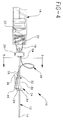
- Fig. 4 is a side elevational view similar to Fig. 1, showing the needle shield in an intermediate and unstable position on the needle cannula.
- Fig. 5 is a cross-sectional view taken along line 5-5 in Fig. 4.
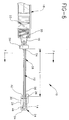
- Fig. 6 is a side elevational view similar to Figs. 1 and 4, showing the needle shield in a second stable condition which prevents use of the needle cannula.
- Fig. 7 is a cross-sectional view taken along line 7-7 in Fig. 1.
- a needle shield in accordance with the subject invention is identified generally by the numeral 10 in Figs. 1-7.
- Needle shield 10 is used with a needle cannula 12 which has a sharply pointed distal tip 14 and a proximal end joined to a needle hub 16.
- Needle cannula 12 is used with a hypodermic syringe 18 which has a luer collar 20 defining a distal end thereof.
- Hub 16 is threadedly engageable with luer collar 20 of hypodermic syringe 18 to place needle cannula 20 in communication with a fluid receiving chamber 22 defined within hypodermic syringe 18.
- Needle shield 10 includes a tip guard 24, an anchor 26 and a spring tether 28 extending therebetween.
- Guard 24 includes a cap 29 having a side wall 30 which is generally tubular in this embodiment. Cap 29 includes opposed proximal and distal ends 32 and 34 respectively.
- An actuating tab 36 extends proximally and slightly outwardly from distal end 32 of side wall 30 and is dimensioned for easy manipulation by a finger of a hand-holding hypodermic syringe 18.
- An end wall 38 extends transversely across distal end 34 and includes a needle receiving aperture 40 extending centrally therethrough.
- Guard 24 further includes a spring lock 46 disposed therein.
- Spring lock 46 is formed from a resilient puncture resistant material such as spring metal, and includes a bent mounting portion 48 that is frictionally embedded in receiving slot 44 of the guard.
- a needle engaging portion 50 that is biased against needle cannula 12.
- Guard 24 is axially movable such that needle engaging portion 50 of spring lock 46 and portions of end wall 38 adjacent aperture 40 slidably engage needle cannula 12.
- Anchor 26 of needle shield 10 is rigidly fixed relative to needle cannula 12 at a location remote from distal tip 14.
- anchor 26 is plastic and is unitarily molded with needle hub 16. In other embodiments, however, anchor 26 may be adhered to needle cannula 12 and/or hub 16. Alternatively, anchor 26 may be a separate component locked to hub 16 or attached directly to the syringe barrel through the use of mechanical means, adhesives, welding or the like.
- Spring tether 28 includes a proximal end 54 connected to guard 24 and a distal end 56 connected to anchor 26.
- Spring tether 28 defines an exposed length "L" as shown in Fig. 6 which permits guard 24 to move distally over tip 14 of needle cannula 12.
- Spring tether 28 is formed from a material that exhibits resiliency, strength and dimensional stability such as fiber glass and metal spring wire with steel spring wire being preferred. More particularly, spring tether 28 is resiliently deflectable into a dynamically stable loop, as shown in Fig. 1, about an axis substantially orthogonal to needle cannula 12.
- regions of looping spring tether 28 adjacent proximal and distal ends 54 and 56 are preferably substantially adjacent and substantially parallel to the longitudinal axis of needle cannula 12.
- Spring tether 28 will try to resiliently return to a substantially linear alignment, with proximal end 54 being resiliently urged in a distal direction and toward needle cannula 12, and distal end 56 being resiliently urged in a proximal direction and toward needle cannula 12.
- guard 24 and anchor 26 efficiently prevent spring tether 28 from springing open.
- the resiliency of spring tether 28 urges guard 24 proximally and toward anchor 26 to define a stable condition which permits use of needle cannula 12.
- the forces exerted on the anchor and the guard by the spring tether are primarily directed perpendicularly to the axis of the needle which increases the frictional forces between the cannula and the tip guard to further stabilize the needle shield.
- Spring tether 28 is initially placed in the looped condition shown in Fig. 1 and 2 by urging guard 24 proximally and into a position substantially adjacent or near anchor 26.
- a removable outer needle shield (not shown) may be telescoped over needle cannula 12 to prevent against accidental needle sticks prior to use of needle cannula 12.
- the outer needle shield may includes a longitudinally extending slot for receiving spring tether 28, and may be frictionally mounted to anchor 26, needle hub 16 or luer collar 20.
- the outer shield may be removed in the conventional manner to enable use of needle cannula 12 and hypodermic syringe 18.
- the thin spring tether 28 will provide virtually no physical or visual obstruction. Hence, a health care worker can accurately orient the bevel at tip 14 of needle cannula 12 and can target a precise location on the patient and can visually gauge the depth of injection.
- length "L" of spring tether 28 is selected to position guard 24 over distal tip 14 of needle cannula 12 when spring tether 28 is in the linear alignment shown in Fig. 6. Additionally, in this position, needle engaging portion 50 of spring lock 46 will have passed distally beyond tip 14 of needle cannula 12. The resiliency of spring lock 46 will urge needle engaging portion 50 thereof over distal tip 14 as shown in Fig. 6 and 7. In this position, spring tether 28 prevents further distal movement of guard 24 while spring lock 46 prevents a return proximal movement of guard 26. Thus, distal tip 14 of needle cannula 12 is safely protected within guard 24 to prevent accidental needle sticks or intentional reuse.
- Fig. 8 illustrates another embodiment of the needle shield of the present invention.
- the spring tether performs in substantially the same way as in the embodiment of Figs. 1-7.
- the means for preventing the tip guard from returning to the retracted position after it is in the needle protecting position is different.
- the embodiment of Fig. 8 includes spring tether 28 and tip guard 74.
- Tip guard 74 includes proximal end 82, distal end 84 and end wall 88 at the distal end running across the distal end of the tip guard.
- End wall 88 includes needle receiving aperture 90 which is generally aligned with tubular side wall 80 of the tip guard.
- Activating tab 86 is provided for application of digital pressure on the tip guard.
- the assembly of resilient spring tether 28 and tip guard 74 is made, so that at rest, the axis of needle receiving aperture 90 is at an angle to the longitudinal axis of the spring tether 28.
- the needle cannula forces the alignment of the axis of the needle receiving aperture in the tip guard to align with the longitudinal axis of the needle cannula.
- the tip guard is fully extended in the needle covering position it will assume the orientation of its assembly as shown in Fig. 8.
- the misalignment causes the needle tip 64 to move out of alignment with needle receiving aperture 90 and to contact the inside of end wall 88. Proximally directed force will cause needle tip 64 to embed itself into end wall 88, thus preventing re-exposure of the needle cannula.
- spring tether 28 has been depicted as being unitary with both guard 24 and anchor 26.
- a separate spring tether may be securely connected to a cap and anchor.
- This separate spring tether may be formed from any material exhibiting appropriate strength, resiliency and dimensional stability, such as a a metallic spring wire.
- spring lock 46 may not be required for some embodiments.
- needle shield 28 may be used with medical implements and needle configurations for other than hypodermic syringes, such as the dual pointed needle used to transfer blood from a patient's vein and an evacuated receptacle.
Landscapes
- Health & Medical Sciences (AREA)
- Engineering & Computer Science (AREA)
- Heart & Thoracic Surgery (AREA)
- Vascular Medicine (AREA)
- Anesthesiology (AREA)
- Biomedical Technology (AREA)
- Environmental & Geological Engineering (AREA)
- Hematology (AREA)
- Life Sciences & Earth Sciences (AREA)
- Animal Behavior & Ethology (AREA)
- General Health & Medical Sciences (AREA)
- Public Health (AREA)
- Veterinary Medicine (AREA)
- Infusion, Injection, And Reservoir Apparatuses (AREA)
- Finger-Pressure Massage (AREA)
Abstract
Description
- The subject invention relates to single-handedly actuatable safety shields for needles to prevent accidental needle sticks.
- Accidental sticks with a used medical implement can transmit disease. Consequently many prior art hypodermic needles, blood collection needles, catheter needles and other sharply pointed medical implements are provided with a safety shield. The safety shield is intended to be placed over the sharply pointed tip of the medical implement immediately after removing the medical implement from the patient.
- Some prior art safety shields define a rigid cap that can be telescoped in a proximal direction over the point of the needle cannula or other such medical implement. This re-shielding procedure requires the health care worker to hold the pointed medical implement in one hand and the shield in the other. The hands are then moved toward one another to effect the shielding. However, a misalignment during the shielding procedure could cause the accidental stick that the shield is intended to avoid. Additionally, this prior art shield presupposes that the health care worker will have two free hands to complete the shielding and that the shield will be readily available when the needle cannula or other such pointed implement is removed from the patient. In fact, many medial procedures require the health care worker to apply pressure to the penetration site immediately after the needle has been removed. Thus, the health care worker will apply pressure with one hand while manipulating the medical implement with the other hand. The unshielded needle may be placed on a nearby surface for shielding at a later time. This re-shielding easily can be overlooked as the health care worker attends to other needs of the patient. Additionally, the needle shield easily can be moved or misplaced between the initial unshielding and the intended reshielding.
- Other prior art needle shields remain attached to the medical implement to avoid loss. The attachment may be a simple tether extending between the above described shield and the medical implement. Upon completion of a medical procedure, the health care worker will perform the two-handed telescoping of the tethered shield in a proximal direction over the point of the needle. This prior art shield avoids problems associated with loss. However, shielding cannot be completed until the health care worker has two free hands and the above-described potential exists for an accidental needle stick during the two-handed shielding procedure.
- Still other prior art needle shields are constructed to enable single handed shielding. For example, some prior art shields are hingedly connected to the medical implement at or near the base of the needle. The shield is a rigid elongate structure, larger than the needle cannula, and open on one side to accept the needle. The shield is rotated away from the needle cannula while the medical implement is being used. The health care worker then uses one finger of the hand holding the medical implement to rotate the shield about the hinge and into a position where the needle cannula is partly surrounded. A variation of this basic design is disclosed in U.S. Patent No, 5,242,417 which shows an over-center hinge connecting a shield to a medical implement. The over-center hinge is stably maintained in a rotational position that enables access to the needle cannula. After use, the shield is rotated toward the needle cannula. Initial rotational movement must overcome biasing forces exerted by the hinge. However, after sufficient rotational movement, the internal resiliency of the hinge urges the shield toward the needle cannula. The prior art hinged shields provide several efficiencies. However, the shield can sometimes interfere with convenient use of the medical implement and can block clear vision of the penetration site.
- Prior art medical implements also include a needle shield that is telescoped over portions of the medical implement. These prior art shields are maintained in a proximal position over the medical implement prior to and during use. The shield then can be telescoped in a distal direction to safely surround the used needle cannula. Prior art shields of this type generally reduce the potential for accidental needle sticks during a shielding operation. However, these prior art shields can add significantly to the size, weight and cost of the medical implement. Additionally, most prior art shields of this type require two-handed activation of the shield. As noted above, two hands may not be available to the health care worker immediately after using the medical implement. Thus, the used medical implement may be kept in an unshielded condition. Prior art telescoping shields have been used with coil springs that are concentric with the needle cannula and that extend between the medical implement and the shield. A latch on the medical implement may keep the coil spring in a compressed condition prior to and during use of the medical implement. The latch may be released by a finger of the hand holding the medical implement to propel the shield distally and into a shielding disposition around to the needle cannula. Coil springs overcome the problem of two-handed activation. However, they further add to the size, weight and cost of the implement. Furthermore, the locks for holding further add to the complexity of the apparatus. These small plastic latches can possibly fail by either misfiring under the force of the spring or not releasing the spring at all.
- The subject invention is directed to a single-handedly activatable safety shield for a needle cannula that may be used with a hypodermic syringe, a blood collection device, a catheter needle, or other medical implement. The needle cannula includes a sharply pointed distal tip and a proximal end that can be placed in communication with the medical implement, such as a hypodermic syringe.
- The safety shield of the subject invention includes a guard that is slidably mounted on the needle cannula for movement between a proximal position where the distal tip of the needle cannula is readily accessible and a distal position where the sharply pointed distal tip of the needle cannula is safely enclosed. The guard may be plastic, but may include a metallic member securely engaged or retained therein. The metallic member may be biased against the needle cannula for sliding movement with the cap along the needle cannula. However, after sufficient movement of the guard distally along the needle cannula, the metallic member will pass the distal tip of the needle cannula. The metallic member will then be biased into a position for protectively covering the distal tip of the needle cannula and preventing a return or proximal movement of the guard.
- The safety shield of the subject invention further includes an elongate spring tether. The spring tether may be formed from a spring wire, fiber glass, plastic or other material that exhibits flexibility, resiliency and adequate degrees of strength and dimensional stability as explained further herein. The spring tether includes opposed proximal and distal ends. The distal end of the spring tether is connected to or unitary with the above described guard of the safety shield. The proximal end of the spring tether is connected to or unitary with an anchor remote from the distal end of the needle cannula. For example, the anchor may be connected to or be unitary with the hub of the needle cannula that enables connection of the needle cannula to a hypodermic syringe or other medical implement. The spring tether defines a length sufficient to enable the guard of the safety shield to protectively enclose the distal tip of the needle cannula without permitting the guard to travel distally beyond the needle cannula.
- The resiliency of the spring tether causes the spring tether to loop into a single coil about an axis substantially orthogonal to the needle cannula when the guard is moved into its proximal position near the anchor. By substantially orthogonal it is meant that the axis crosses the longitudinal axis of the needle cannula rather than being in a substantially parallel relationship with the longitudinal axis of the needle cannula. In this position, the opposed proximal and distal ends of the spring tether are near one another and are substantially axially aligned. Importantly, the spring tether is stable in this looped condition with the guard of the safety shield being conveniently urged in a proximal direction by the resiliency of the spring tether. Although separate latches may be provided they are not required to keep the guard of the safety shield in the proximal position.
- The spring tether of the safety shield is in its looped condition prior to and during use of the needle cannula, with the guard being stably maintained in its proximal position on the needle cannula. In this position the distal tip of the needle cannula is readily visible and accessible for use in its normal manner. Significantly, the spring tether is cross-sectionally very small, and hence provides virtually no visual obstruction. As a result the health care worker can readily observe the puncture site, the orientation of the bevel on the distal tip of the needle cannula, and the depth of injection.
- After withdrawal of the needle cannula from the patient, the health are worker merely exerts a distally directed force on the guard of the safety shield. This force conveniently can be exerted with a finger of the hand in which the medical implement is held by the health care worker. Initial forces exerted on the guard must overcome the biasing forces that maintain the resilient spring tether stably in its looped condition. However, after the spring tether uncoils beyond its point of stability, the inherent resiliency of the spring tether will propel the guard distally along the needle cannula until the spring tether reaches a fully extended and stable condition. The guard attached to the distal end of the spring tether will protectively enclose the distal tip of the needle cannula when the spring tether reaches the fully extended position. As noted above, the guard may include a metallic member that is biased against the needle cannula to slide therealong. When the spring tether is urged into its stable linear condition, the metallic member within the guard will have slid distally beyond the tip of the needle cannula and will biasingly urge itself over the tip of the needle cannula. Thus, the metallic member prevents a return proximal movement of the guard that could otherwise re-expose the tip of the used needle cannula. Conversely, the extended spring tether prevents the guard from moving distally beyond the needle cannula.
- Fig. 1 is a side elevational view showing the needle shield disposed in a first stable position on a needle cannula for permitting use of the needle cannula.
- Fig. 2 is a cross-sectional view taken along line 2-2 in Fig. 1.
- Fig. 3 is a cross-sectional view taken along line 3-3 in Fig. 2.
- Fig. 4 is a side elevational view similar to Fig. 1, showing the needle shield in an intermediate and unstable position on the needle cannula.
- Fig. 5 is a cross-sectional view taken along line 5-5 in Fig. 4.
- Fig. 6 is a side elevational view similar to Figs. 1 and 4, showing the needle shield in a second stable condition which prevents use of the needle cannula.
- Fig. 7 is a cross-sectional view taken along line 7-7 in Fig. 1.
- A needle shield in accordance with the subject invention is identified generally by the numeral 10 in Figs. 1-7.
Needle shield 10 is used with aneedle cannula 12 which has a sharply pointeddistal tip 14 and a proximal end joined to aneedle hub 16.Needle cannula 12 is used with ahypodermic syringe 18 which has aluer collar 20 defining a distal end thereof.Hub 16 is threadedly engageable withluer collar 20 ofhypodermic syringe 18 to placeneedle cannula 20 in communication with afluid receiving chamber 22 defined withinhypodermic syringe 18. -
Needle shield 10 includes atip guard 24, ananchor 26 and aspring tether 28 extending therebetween.Guard 24 includes acap 29 having aside wall 30 which is generally tubular in this embodiment.Cap 29 includes opposed proximal anddistal ends actuating tab 36 extends proximally and slightly outwardly fromdistal end 32 ofside wall 30 and is dimensioned for easy manipulation by a finger of a hand-holdinghypodermic syringe 18. Anend wall 38 extends transversely acrossdistal end 34 and includes aneedle receiving aperture 40 extending centrally therethrough. -
Guard 24 further includes aspring lock 46 disposed therein.Spring lock 46 is formed from a resilient puncture resistant material such as spring metal, and includes a bent mountingportion 48 that is frictionally embedded in receivingslot 44 of the guard. Aneedle engaging portion 50 that is biased againstneedle cannula 12.Guard 24 is axially movable such thatneedle engaging portion 50 ofspring lock 46 and portions ofend wall 38adjacent aperture 40 slidably engageneedle cannula 12. -
Anchor 26 ofneedle shield 10 is rigidly fixed relative toneedle cannula 12 at a location remote fromdistal tip 14. In the embodiment depicted herein,anchor 26 is plastic and is unitarily molded withneedle hub 16. In other embodiments, however,anchor 26 may be adhered toneedle cannula 12 and/orhub 16. Alternatively,anchor 26 may be a separate component locked tohub 16 or attached directly to the syringe barrel through the use of mechanical means, adhesives, welding or the like. -
Spring tether 28 includes aproximal end 54 connected to guard 24 and adistal end 56 connected to anchor 26.Spring tether 28 defines an exposed length "L" as shown in Fig. 6 which permitsguard 24 to move distally overtip 14 ofneedle cannula 12.Spring tether 28 is formed from a material that exhibits resiliency, strength and dimensional stability such as fiber glass and metal spring wire with steel spring wire being preferred. More particularly,spring tether 28 is resiliently deflectable into a dynamically stable loop, as shown in Fig. 1, about an axis substantially orthogonal toneedle cannula 12. In this looped condition, regions of loopingspring tether 28 adjacent proximal anddistal ends needle cannula 12.Spring tether 28 will try to resiliently return to a substantially linear alignment, withproximal end 54 being resiliently urged in a distal direction and towardneedle cannula 12, anddistal end 56 being resiliently urged in a proximal direction and towardneedle cannula 12. However,guard 24 andanchor 26 efficiently preventspring tether 28 from springing open. Hence, the resiliency ofspring tether 28 urges guard 24 proximally and towardanchor 26 to define a stable condition which permits use ofneedle cannula 12. Also, when the guard is in the retracted position the forces exerted on the anchor and the guard by the spring tether are primarily directed perpendicularly to the axis of the needle which increases the frictional forces between the cannula and the tip guard to further stabilize the needle shield. -
Spring tether 28 is initially placed in the looped condition shown in Fig. 1 and 2 by urgingguard 24 proximally and into a position substantially adjacent ornear anchor 26. A removable outer needle shield (not shown) may be telescoped overneedle cannula 12 to prevent against accidental needle sticks prior to use ofneedle cannula 12. The outer needle shield may includes a longitudinally extending slot for receivingspring tether 28, and may be frictionally mounted to anchor 26,needle hub 16 orluer collar 20. The outer shield may be removed in the conventional manner to enable use ofneedle cannula 12 andhypodermic syringe 18. Thethin spring tether 28 will provide virtually no physical or visual obstruction. Hence, a health care worker can accurately orient the bevel attip 14 ofneedle cannula 12 and can target a precise location on the patient and can visually gauge the depth of injection. - After withdrawal of
needle cannula 12 from the patient, the health care worker exerts a distally directed force on actuatingtab 36 ofguard 24. This distally directed force causes guard 24 to move distally alongneedle cannula 12. This initial distal movement ofguard 24 must overcome the resiliency ofspring tether 28. However, resistance ofspring tether 28 is small compared to the forced exerted by a finger of the health care worker. Resiliency ofspring tether 28 prevents the spring tether from collapsing onto itself in response to distal forces exerted by the health care worker onguard 24. Rather,spring tether 28 will effectively be rotated from the Fig. 2 orientation where the axis ofspring tether 28 is substantially orthogonal toneedle cannula 12, into the Fig. 4 and 5 orientation where the axis of the loop becomes more aligned to longitudinal axis of theneedle cannula 12. The component of the resilient forces that initially urgedguard 24 in a proximal direction become less asguard 24 moves distally and asspring tether 28 gradually opens and rotates. At approximately the position depicted in Figs. 4 and 5, the inherent resiliency ofspring tether 28 will begin to propelguard 24 distally. These distal forces will continue untilspring tether 28 achieves the linear alignment depicted in Figs. 6 and 7. - As noted above, length "L" of
spring tether 28 is selected to positionguard 24 overdistal tip 14 ofneedle cannula 12 whenspring tether 28 is in the linear alignment shown in Fig. 6. Additionally, in this position,needle engaging portion 50 ofspring lock 46 will have passed distally beyondtip 14 ofneedle cannula 12. The resiliency ofspring lock 46 will urgeneedle engaging portion 50 thereof overdistal tip 14 as shown in Fig. 6 and 7. In this position,spring tether 28 prevents further distal movement ofguard 24 whilespring lock 46 prevents a return proximal movement ofguard 26. Thus,distal tip 14 ofneedle cannula 12 is safely protected withinguard 24 to prevent accidental needle sticks or intentional reuse. - Fig. 8 illustrates another embodiment of the needle shield of the present invention. In this embodiment the spring tether performs in substantially the same way as in the embodiment of Figs. 1-7. However, in the embodiment of Fig. 8 the means for preventing the tip guard from returning to the retracted position after it is in the needle protecting position is different. Specifically, the embodiment of Fig. 8 includes
spring tether 28 andtip guard 74.Tip guard 74 includesproximal end 82,distal end 84 andend wall 88 at the distal end running across the distal end of the tip guard.End wall 88 includesneedle receiving aperture 90 which is generally aligned withtubular side wall 80 of the tip guard. Activatingtab 86 is provided for application of digital pressure on the tip guard. The assembly ofresilient spring tether 28 andtip guard 74 is made, so that at rest, the axis ofneedle receiving aperture 90 is at an angle to the longitudinal axis of thespring tether 28. However, when the tip guard is in its retracted proximal position on the needle cannula, the needle cannula forces the alignment of the axis of the needle receiving aperture in the tip guard to align with the longitudinal axis of the needle cannula. However, when the tip guard is fully extended in the needle covering position it will assume the orientation of its assembly as shown in Fig. 8. The misalignment causes theneedle tip 64 to move out of alignment withneedle receiving aperture 90 and to contact the inside ofend wall 88. Proximally directed force will causeneedle tip 64 to embed itself intoend wall 88, thus preventing re-exposure of the needle cannula. - The invention has been described with respect to a limited number of embodiments. However, it is to be understood that variations can be provided. In particular,
spring tether 28 has been depicted as being unitary with bothguard 24 andanchor 26. However, a separate spring tether may be securely connected to a cap and anchor. This separate spring tether may be formed from any material exhibiting appropriate strength, resiliency and dimensional stability, such as a a metallic spring wire. Additionally,spring lock 46 may not be required for some embodiments. Finally, as noted above,needle shield 28 may be used with medical implements and needle configurations for other than hypodermic syringes, such as the dual pointed needle used to transfer blood from a patient's vein and an evacuated receptacle.
Claims (10)
- A safety shield comprising an elongate needle cannula having a proximal end and an opposed distal tip;
an anchor disposed substantially adjacent said proximal end of said needle cannula;
a guard slidably movable along said needle cannula from a proximal position substantially adjacent said anchor to a distal position where said tip guard protectively encloses said distal tip of said needle cannula; and
an elongate spring tether formed from a resiliently deflectable material, said spring tether having a proximal end connected to said anchor and a distal end connected to said guard, said spring tether being deflectable into a loop and about an axis substantially orthogonal to said needle cannula when said guard is in said proximal position, said spring tether defining a length for permitting said guard to slidably move into said distal position while preventing complete separation of said guard from said needle cannula, and whereby said resiliency of said spring tether propels said guard to said distal position after an initial distal movement of said guard toward said distal position. - The safety shield of Claim 2, wherein said anchor, said guard and said spring tether are unitary with one another and formed of plastic material.
- The safety shield of Claim 1, wherein said spring tether is formed from fiber glass.
- The safety shield of Claim 1, wherein said spring tether is formed from a resilient metallic wire.
- The safety shield of Claim 1, wherein said guard includes an actuator tab projecting generally transversely away from said needle cannula for manually urging said guard distally away from said proximal position and against said biasing forces of said spring tether.
- The safety shield of Claim 1, wherein said needle cannula includes a mounting hub affixed to said proximal end of said needle cannula, said anchor being securely connected to said needle hub.
- The safety shield of Claim 6, wherein said anchor is unitary with said hub.
- The safety shield of Claim 1, wherein said guard includes a spring lock disposed therein, said spring lock being biased to contact said needle cannula as said guard moves from said proximal position toward said distal position, said spring lock being configured for biasingly engaging over said distal tip of said needle cannula when said guard is in said distal position to prevent proximal motion of said guard.
- The safety shield of Claim 8, wherein said guard defines a generally cylindrical cap surrounding said needle cannula, said spring lock being lockingly retained within said cap of said guard.
- The safety shield of Claim 1 further including an elongate syringe barrel having a distal end, a proximal end and a sidewall therebetween, said proximal end of said needle connected to said distal end of said barrel.
Applications Claiming Priority (2)
| Application Number | Priority Date | Filing Date | Title |
|---|---|---|---|
| US296575 | 1994-08-26 | ||
| US08/296,575 US5423766A (en) | 1994-08-26 | 1994-08-26 | Safety shield having spring tether |
Publications (2)
| Publication Number | Publication Date |
|---|---|
| EP0702972A1 true EP0702972A1 (en) | 1996-03-27 |
| EP0702972B1 EP0702972B1 (en) | 2002-09-25 |
Family
ID=23142621
Family Applications (1)
| Application Number | Title | Priority Date | Filing Date |
|---|---|---|---|
| EP95305147A Expired - Lifetime EP0702972B1 (en) | 1994-08-26 | 1995-07-24 | Safety shield having spring tether |
Country Status (6)
| Country | Link |
|---|---|
| US (1) | US5423766A (en) |
| EP (1) | EP0702972B1 (en) |
| JP (1) | JP2781750B2 (en) |
| CA (1) | CA2156995C (en) |
| DE (1) | DE69528330T2 (en) |
| ES (1) | ES2183856T3 (en) |
Cited By (4)
| Publication number | Priority date | Publication date | Assignee | Title |
|---|---|---|---|---|
| US6595955B2 (en) | 2001-03-15 | 2003-07-22 | Specialized Health Products, Inc. | Safety shield for medical needles |
| US6796962B2 (en) | 2001-03-15 | 2004-09-28 | Specialized Health Products, Inc. | Safety shield for medical needles |
| EP1707230B1 (en) | 2001-02-26 | 2016-02-17 | B. Braun Melsungen AG | Injection needle with a protection element for the needle tip |
| US9539398B2 (en) | 2001-03-15 | 2017-01-10 | Specialized Health Products, Inc. | Safety shield for medical needles |
Families Citing this family (112)
| Publication number | Priority date | Publication date | Assignee | Title |
|---|---|---|---|---|
| US5176655A (en) * | 1990-11-08 | 1993-01-05 | Mbo Laboratories, Inc. | Disposable medical needle and catheter placement assembly having full safety enclosure means |
| US5584818A (en) * | 1994-08-22 | 1996-12-17 | Morrison; David | Safety hypodermic needle and shielding cap assembly |
| US5584810A (en) * | 1995-07-11 | 1996-12-17 | Becton Dickinson And Company | Needle point guard assembly |
| AU729720B2 (en) | 1996-02-27 | 2001-02-08 | B. Braun Melsungen Ag | Needle tip guard for hypodermic needles |
| US5879337A (en) * | 1997-02-27 | 1999-03-09 | Injectimed, Inc. | Needle tip guard for hypodermic needles |
| US5817069A (en) * | 1996-02-28 | 1998-10-06 | Vadus, Inc. | Valve assembly |
| US5651772A (en) * | 1996-02-28 | 1997-07-29 | Aeroquip Corporation | Needle guard assembly |
| CA2261938C (en) * | 1996-08-07 | 2004-07-13 | Vadus, Inc. | Needle protector |
| US5725503A (en) * | 1996-08-07 | 1998-03-10 | Aeroquip Corporation | Ratcheting needle protector assembly |
| US5954698A (en) | 1997-01-08 | 1999-09-21 | Vadus, Inc. | Catheter apparatus having valved catheter hub and needle protector |
| US6080137A (en) * | 1997-01-08 | 2000-06-27 | Vadus, Inc. | Needle protector |
| US6117108A (en) * | 1997-08-20 | 2000-09-12 | Braun Melsungen Ag | Spring clip safety IV catheter |
| US7125397B2 (en) * | 1997-08-20 | 2006-10-24 | B. Braun Melsungen Ag | Protective device for an injection needle |
| US8382721B2 (en) | 1997-08-20 | 2013-02-26 | B. Braun Melsungen Ag | Spring clip safety IV catheter |
| US8211070B2 (en) | 1997-08-20 | 2012-07-03 | B. Braun Melsungen Ag | Spring clip safety IV catheter |
| US6616630B1 (en) * | 1997-08-20 | 2003-09-09 | B. Braun Melsungen A.G. | Spring clip safety IV catheter |
| FR2767469B1 (en) | 1997-08-25 | 2000-06-16 | Raphael Mosseri | PROTECTION DEVICE FOR A CUTTING AND / OR PERFORATING TOOL |
| US5910132A (en) * | 1998-01-06 | 1999-06-08 | B. Braun Medical Inc. | Safety IV catheter guard |
| US6261264B1 (en) * | 1999-07-23 | 2001-07-17 | Frank A. Tamaro | Safety cap assembly for needles |
| US8226617B2 (en) | 1999-11-04 | 2012-07-24 | Tyco Healthcare Group Lp | Safety shield apparatus and mounting structure for use with medical needle devices |
| US7198618B2 (en) * | 1999-11-04 | 2007-04-03 | Tyco Healthcare Group Lp | Safety shield for medical needles |
| US6592556B1 (en) | 2000-07-19 | 2003-07-15 | Tyco Healthcare Group Lp | Medical needle safety apparatus and methods |
| US7029461B2 (en) | 1999-11-04 | 2006-04-18 | Tyco Healthcare Group Lp | Safety shield for medical needles |
| US6280420B1 (en) | 1999-11-04 | 2001-08-28 | Specialized Health Products | Reaccessible medical needle safety devices and methods |
| DE29921084U1 (en) * | 1999-12-01 | 2000-02-17 | B. Braun Melsungen Ag, 34212 Melsungen | Short catheter |
| US6537259B1 (en) * | 2000-03-07 | 2003-03-25 | Becton, Dickinson And Company | Passive safety device |
| US6585704B2 (en) * | 2001-01-29 | 2003-07-01 | B. Braun Medical, Inc. | Method of retaining a tip protector on a needle with a curved tip |
| US7004927B2 (en) * | 2001-03-15 | 2006-02-28 | Specialized Health Products, Inc. | Safety shield for medical needles |
| US7179244B2 (en) * | 2001-03-15 | 2007-02-20 | Specialized Health Products, Inc. | Resettable safety shield for medical needles |
| US6984213B2 (en) * | 2001-03-15 | 2006-01-10 | Specialized Health Products, Inc. | Biopsy needle device |
| US6902546B2 (en) | 2001-03-15 | 2005-06-07 | Specialized Health Products, Inc. | Safety shield for medical needles |
| DE20106697U1 (en) * | 2001-04-18 | 2001-10-31 | B. Braun Melsungen Ag, 34212 Melsungen | Catheter introducer |
| US8100857B2 (en) * | 2001-07-25 | 2012-01-24 | B. Braun Melsungen Ag | Method and apparatus for indicating or covering a percutaneous puncture site |
| US6984223B2 (en) | 2001-11-13 | 2006-01-10 | Becton, Dickinson And Company | Needle safety device |
| US6926700B2 (en) * | 2002-03-19 | 2005-08-09 | Becton, Dickinson And Company | Needle assembly |
| US20030181870A1 (en) * | 2002-03-19 | 2003-09-25 | Becton, Dickinson And Company | Needle device |
| CA2422472A1 (en) * | 2002-03-19 | 2003-09-19 | Volker Niermann | Needle assembly |
| CA2422516A1 (en) * | 2002-03-19 | 2003-09-19 | Becton, Dickinson And Company | Needle device |
| AU2003201341A1 (en) * | 2002-03-20 | 2003-10-16 | Becton, Dickinson And Company | Needle assembly |
| ES2240875T3 (en) * | 2002-03-21 | 2005-10-16 | Becton, Dickinson And Company | SAFETY NEEDLE DEVICE WITH A Dorsal FIN. |
| US7001363B2 (en) * | 2002-04-05 | 2006-02-21 | F. Mark Ferguson | Safety shield for medical needles |
| US7578805B2 (en) * | 2002-05-15 | 2009-08-25 | Becton, Dickinson And Company | Blood collection device |
| US20040049155A1 (en) * | 2002-06-06 | 2004-03-11 | Schramm John B. | Needle tip protector |
| US6726658B2 (en) | 2002-06-18 | 2004-04-27 | Milestone Scientific, Inc. | Safety IV catheter infusion device |
| DE20210394U1 (en) | 2002-07-04 | 2002-09-12 | B. Braun Melsungen Ag, 34212 Melsungen | catheter introducer |
| US7458954B2 (en) * | 2002-11-07 | 2008-12-02 | Specialized Health Products, Inc. | Safety shield for medical needles |
| US7422573B2 (en) * | 2002-12-19 | 2008-09-09 | Becton, Dickinson And Company | Forward blunting wingset with leaf spring driven shield |
| US7041066B2 (en) * | 2003-03-13 | 2006-05-09 | Becton, Dickinson & Company | Needle assembly |
| US7097637B2 (en) * | 2003-08-27 | 2006-08-29 | C. R. Bard, Inc. | Safety needle with positive flush |
| US7988664B2 (en) * | 2004-11-01 | 2011-08-02 | Tyco Healthcare Group Lp | Locking clip with trigger bushing |
| US7226434B2 (en) | 2003-10-31 | 2007-06-05 | Tyco Healthcare Group Lp | Safety shield |
| EP1696979B1 (en) * | 2003-11-25 | 2012-08-08 | Specialized Health Products Inc. | Resettable safety shield for medical needles |
| US7150725B2 (en) * | 2003-12-17 | 2006-12-19 | Becton Dickinson And Company | Passive activated safety blood collection set |
| WO2005060679A2 (en) * | 2003-12-18 | 2005-07-07 | Specialized Health Products, Inc. | Safety shield for medical needles |
| US7513888B2 (en) * | 2004-02-17 | 2009-04-07 | Smiths Medical Asd, Inc. | Needle guards |
| US20050222539A1 (en) * | 2004-03-30 | 2005-10-06 | Pediamed Pharmaceuticals, Inc. | Automatic injection device |
| US7430278B2 (en) * | 2004-07-09 | 2008-09-30 | General Electric Company | Insulation methods and arrangements for an X-ray generator |
| US20060058742A1 (en) * | 2004-09-15 | 2006-03-16 | Sedo Cha | Protective cover for arterial needle |
| US7828773B2 (en) | 2005-07-11 | 2010-11-09 | Covidien Ag | Safety reset key and needle assembly |
| US7850650B2 (en) | 2005-07-11 | 2010-12-14 | Covidien Ag | Needle safety shield with reset |
| US7905857B2 (en) | 2005-07-11 | 2011-03-15 | Covidien Ag | Needle assembly including obturator with safety reset |
| US7314462B2 (en) * | 2005-04-12 | 2008-01-01 | Span-America Medical Systems, Inc. | Passive needle-stick protector |
| JP4559284B2 (en) * | 2005-04-21 | 2010-10-06 | 日本シャーウッド株式会社 | Indwelling needle set |
| US20060276747A1 (en) | 2005-06-06 | 2006-12-07 | Sherwood Services Ag | Needle assembly with removable depth stop |
| CA2550114C (en) | 2005-06-20 | 2013-11-19 | Sherwood Services, Ag | Safety shield for medical needles |
| US7731692B2 (en) | 2005-07-11 | 2010-06-08 | Covidien Ag | Device for shielding a sharp tip of a cannula and method of using the same |
| US20070038187A1 (en) * | 2005-08-08 | 2007-02-15 | Albert Sean J | Needle guard mechanism with anti-rotation feature |
| US7632243B2 (en) * | 2005-08-08 | 2009-12-15 | Smiths Medical Asd, Inc. | Duckbill catheter release mechanism |
| US8162881B2 (en) * | 2005-08-08 | 2012-04-24 | Smiths Medical Asd, Inc. | Needle guard mechanism with angled strut wall |
| US8403886B2 (en) * | 2005-08-08 | 2013-03-26 | Smiths Medical Asd, Inc. | Needle guard clip with lip |
| US7654735B2 (en) | 2005-11-03 | 2010-02-02 | Covidien Ag | Electronic thermometer |
| US7658725B2 (en) | 2006-02-16 | 2010-02-09 | Smiths Medical Asd, Inc. | Enclosed needle device with duckbill release mechanism |
| JP4969642B2 (en) | 2006-03-21 | 2012-07-04 | タイコ ヘルスケアー グループ リミテッド パートナーシップ | Passive latching safety shield for injection devices |
| US8162904B2 (en) | 2006-03-29 | 2012-04-24 | Terumo Kabushiki Kaisha | Needle protector |
| US9358348B2 (en) * | 2006-06-14 | 2016-06-07 | Covidien Lp | Safety shield for medical needles |
| US8382718B2 (en) | 2006-07-31 | 2013-02-26 | B. Braun Melsungen Ag | Needle assembly and components thereof |
| US8308691B2 (en) | 2006-11-03 | 2012-11-13 | B. Braun Melsungen Ag | Catheter assembly and components thereof |
| JP4994775B2 (en) | 2006-10-12 | 2012-08-08 | 日本コヴィディエン株式会社 | Needle point protector |
| US8057431B2 (en) | 2006-12-21 | 2011-11-15 | B. Braun Melsungen Ag | Hinged cap for needle device |
| CN101099876B (en) * | 2007-08-15 | 2012-07-04 | 张亚根 | Active type safety syringe and safety injection needle |
| WO2009042874A1 (en) * | 2007-09-27 | 2009-04-02 | Tyco Healthcare Group Lp | I.v. catheter assembly and needle safety device |
| US8357104B2 (en) | 2007-11-01 | 2013-01-22 | Coviden Lp | Active stylet safety shield |
| DE602008002806D1 (en) | 2007-12-20 | 2010-11-11 | Tyco Healthcare | Locking cap arrangement with spring-loaded collar |
| NZ589266A (en) * | 2008-04-23 | 2012-03-30 | Gary Christopher Jones | A retractable cover for the tip of a sharp medical device such as a needle or syringe |
| US8439870B2 (en) * | 2008-09-10 | 2013-05-14 | B. Braun Medical Inc. | Safety needle assembly and methods |
| US8382751B2 (en) | 2009-09-10 | 2013-02-26 | Covidien Lp | System and method for power supply noise reduction |
| EP2585145B1 (en) | 2010-08-19 | 2014-03-05 | West Pharmaceutical Services, Inc. | Rigid needle shield |
| RU2584388C2 (en) | 2010-11-22 | 2016-05-20 | Б. Браун Мельзунген Аг | Hinged panel device and related methods |
| US9238104B2 (en) | 2011-02-28 | 2016-01-19 | Injectimed, Inc. | Needle guard |
| US8764711B2 (en) | 2011-02-28 | 2014-07-01 | Injectimed, Inc. | Needle guard |
| EP2517751B8 (en) | 2011-04-27 | 2018-02-28 | Kpr U.S., Llc | Safety IV catheter assemblies |
| WO2012170805A2 (en) * | 2011-06-09 | 2012-12-13 | Knee Creations, Llc | Instruments and devices for subchondral joint repair |
| US8591467B2 (en) | 2011-07-25 | 2013-11-26 | Covidien Lp | Vascular access assembly and safety device |
| EP2760521B1 (en) | 2011-09-26 | 2016-01-06 | Covidien LP | Safety iv catheter and needle assembly |
| WO2013048975A1 (en) | 2011-09-26 | 2013-04-04 | Covidien Lp | Safety catheter |
| WO2013056223A1 (en) | 2011-10-14 | 2013-04-18 | Covidien Lp | Safety iv catheter assembly |
| CA2854003C (en) | 2011-11-07 | 2020-07-14 | Safety Syringes, Inc. | Contact trigger release needle guard |
| US8414539B1 (en) | 2011-12-27 | 2013-04-09 | B. Braun Melsungen Ag | Needle tip guard for percutaneous entry needles |
| US10524710B2 (en) | 2012-11-15 | 2020-01-07 | Becton, Dickinson And Company | Passive double drive member activated safety blood collection device |
| ITFO20130002A1 (en) * | 2013-02-07 | 2013-05-09 | Antonio Agnoletti | NEEDLE INVERSE CATHETER WITH TOTAL SAFETY DEVICES |
| US10500376B2 (en) | 2013-06-07 | 2019-12-10 | Becton, Dickinson And Company | IV catheter having external needle shield and internal blood control septum |
| US9861784B2 (en) | 2013-12-03 | 2018-01-09 | Becton, Dickinson And Company | Blood collection device with double pivot shields |
| US9555221B2 (en) | 2014-04-10 | 2017-01-31 | Smiths Medical Asd, Inc. | Constant force hold tip protector for a safety catheter |
| SG10202007098SA (en) | 2014-04-18 | 2020-08-28 | Becton Dickinson Co | Needle capture safety interlock for catheter |
| US11511052B2 (en) | 2014-11-10 | 2022-11-29 | Becton, Dickinson And Company | Safety IV catheter with V-clip interlock and needle tip capture |
| US10029049B2 (en) | 2015-03-19 | 2018-07-24 | B. Braun Melsungen Ag | Hinged shield assemblies and related methods |
| JP7091350B2 (en) | 2016-10-18 | 2022-06-27 | パイパー・アクセス、エルエルシー | Intraosseous access devices, systems, and methods |
| US11484341B2 (en) | 2017-03-07 | 2022-11-01 | Piper Access, Llc | Safety shields for elongated instruments and related systems and methods |
| WO2018165339A1 (en) | 2017-03-10 | 2018-09-13 | Piper Access, Llc. | Securement devices, systems, and methods |
| EP4218622A1 (en) | 2018-02-20 | 2023-08-02 | Piper Access, LLC | Drilling devices and related systems |
| EP4028104A4 (en) | 2019-09-10 | 2023-12-13 | MedSource International LLC | An intravenous catheter device |
| US11707601B2 (en) * | 2020-02-24 | 2023-07-25 | Becton, Dickinson And Company | Cover to facilitate reduced-touch insertion of a catheter and related systems and methods |
Citations (9)
| Publication number | Priority date | Publication date | Assignee | Title |
|---|---|---|---|---|
| US4955866A (en) * | 1988-10-19 | 1990-09-11 | University Of Florida | Hypodermic needle recapping device |
| US5013305A (en) * | 1988-06-29 | 1991-05-07 | Opie Eric A | Needle safety system and method |
| US5051109A (en) * | 1990-07-16 | 1991-09-24 | Simon Alexander Z | Protector for catheter needle |
| US5053017A (en) * | 1990-02-28 | 1991-10-01 | Chamuel Steven R | Hypodermic needle safety clip |
| US5092851A (en) * | 1991-01-04 | 1992-03-03 | Ragner & Staab Associates | Safety needle with spring-loaded shield |
| US5242417A (en) | 1992-01-13 | 1993-09-07 | Paudler Gary M | Self closing hinged syringe guard |
| US5246427A (en) * | 1992-11-25 | 1993-09-21 | Sturman Martin F | Safety hypodermic needle and shielding cap assembly |
| US5250031A (en) * | 1992-12-14 | 1993-10-05 | The George Washington University | Locking needle cover |
| US5348544A (en) * | 1993-11-24 | 1994-09-20 | Becton, Dickinson And Company | Single-handedly actuatable safety shield for needles |
Family Cites Families (3)
| Publication number | Priority date | Publication date | Assignee | Title |
|---|---|---|---|---|
| JPS63192454A (en) * | 1987-02-03 | 1988-08-09 | 眞島 康雄 | Injection needle connected to cylindrical cap by string |
| DE4201228A1 (en) * | 1991-01-22 | 1992-07-23 | Ricardo Sheath Oxford Steyn | PROTECTIVE DEVICE FOR THE NEEDLE OF A SYRINGE |
| US5344408A (en) * | 1993-08-06 | 1994-09-06 | Becton, Dickinson And Company | Break-away safety shield for needle cannula |
-
1994
- 1994-08-26 US US08/296,575 patent/US5423766A/en not_active Expired - Lifetime
-
1995
- 1995-07-24 ES ES95305147T patent/ES2183856T3/en not_active Expired - Lifetime
- 1995-07-24 DE DE69528330T patent/DE69528330T2/en not_active Expired - Fee Related
- 1995-07-24 EP EP95305147A patent/EP0702972B1/en not_active Expired - Lifetime
- 1995-08-22 JP JP7213661A patent/JP2781750B2/en not_active Expired - Fee Related
- 1995-08-25 CA CA002156995A patent/CA2156995C/en not_active Expired - Fee Related
Patent Citations (9)
| Publication number | Priority date | Publication date | Assignee | Title |
|---|---|---|---|---|
| US5013305A (en) * | 1988-06-29 | 1991-05-07 | Opie Eric A | Needle safety system and method |
| US4955866A (en) * | 1988-10-19 | 1990-09-11 | University Of Florida | Hypodermic needle recapping device |
| US5053017A (en) * | 1990-02-28 | 1991-10-01 | Chamuel Steven R | Hypodermic needle safety clip |
| US5051109A (en) * | 1990-07-16 | 1991-09-24 | Simon Alexander Z | Protector for catheter needle |
| US5092851A (en) * | 1991-01-04 | 1992-03-03 | Ragner & Staab Associates | Safety needle with spring-loaded shield |
| US5242417A (en) | 1992-01-13 | 1993-09-07 | Paudler Gary M | Self closing hinged syringe guard |
| US5246427A (en) * | 1992-11-25 | 1993-09-21 | Sturman Martin F | Safety hypodermic needle and shielding cap assembly |
| US5250031A (en) * | 1992-12-14 | 1993-10-05 | The George Washington University | Locking needle cover |
| US5348544A (en) * | 1993-11-24 | 1994-09-20 | Becton, Dickinson And Company | Single-handedly actuatable safety shield for needles |
Cited By (4)
| Publication number | Priority date | Publication date | Assignee | Title |
|---|---|---|---|---|
| EP1707230B1 (en) | 2001-02-26 | 2016-02-17 | B. Braun Melsungen AG | Injection needle with a protection element for the needle tip |
| US6595955B2 (en) | 2001-03-15 | 2003-07-22 | Specialized Health Products, Inc. | Safety shield for medical needles |
| US6796962B2 (en) | 2001-03-15 | 2004-09-28 | Specialized Health Products, Inc. | Safety shield for medical needles |
| US9539398B2 (en) | 2001-03-15 | 2017-01-10 | Specialized Health Products, Inc. | Safety shield for medical needles |
Also Published As
| Publication number | Publication date |
|---|---|
| ES2183856T3 (en) | 2003-04-01 |
| US5423766A (en) | 1995-06-13 |
| EP0702972B1 (en) | 2002-09-25 |
| JPH0871151A (en) | 1996-03-19 |
| CA2156995A1 (en) | 1996-02-27 |
| DE69528330T2 (en) | 2003-05-15 |
| DE69528330D1 (en) | 2002-10-31 |
| CA2156995C (en) | 1999-02-23 |
| JP2781750B2 (en) | 1998-07-30 |
Similar Documents
| Publication | Publication Date | Title |
|---|---|---|
| US5423766A (en) | Safety shield having spring tether | |
| US5348544A (en) | Single-handedly actuatable safety shield for needles | |
| US6878136B2 (en) | Huber needle with anti-rebound safety mechanism | |
| EP1449560B1 (en) | Medical device with shield having a retractable needle | |
| US6936036B2 (en) | Blood collection agency | |
| EP1951342B1 (en) | Single-handedly actuatable shield for needles | |
| JP2739932B2 (en) | Needle tip barrier | |
| EP1362608B1 (en) | Shieldable needle device | |
| US6918894B2 (en) | Huber needle with anti-rebound safety mechanism | |
| US7422573B2 (en) | Forward blunting wingset with leaf spring driven shield | |
| EP1346738B1 (en) | Safety needle device with a dorsal fin | |
| EP1346741A2 (en) | Shieldable needle assembly with biased safety shield | |
| EP1293162A2 (en) | Needle for blood sampling with a safety shield | |
| US20030220587A1 (en) | Medical device | |
| EP3436127B1 (en) | Cannula capture mechanism | |
| WO1998057689A1 (en) | Shield for catheter introducer needles | |
| US7144388B2 (en) | Selectively passive shieldable medical needle device | |
| MXPA97003645A (en) | Assemble impulsed needle protector manualme |
Legal Events
| Date | Code | Title | Description |
|---|---|---|---|
| PUAI | Public reference made under article 153(3) epc to a published international application that has entered the european phase |
Free format text: ORIGINAL CODE: 0009012 |
|
| AK | Designated contracting states |
Kind code of ref document: A1 Designated state(s): DE ES FR GB IT |
|
| 17P | Request for examination filed |
Effective date: 19960916 |
|
| 17Q | First examination report despatched |
Effective date: 20010504 |
|
| GRAG | Despatch of communication of intention to grant |
Free format text: ORIGINAL CODE: EPIDOS AGRA |
|
| GRAG | Despatch of communication of intention to grant |
Free format text: ORIGINAL CODE: EPIDOS AGRA |
|
| GRAH | Despatch of communication of intention to grant a patent |
Free format text: ORIGINAL CODE: EPIDOS IGRA |
|
| GRAG | Despatch of communication of intention to grant |
Free format text: ORIGINAL CODE: EPIDOS AGRA |
|
| GRAH | Despatch of communication of intention to grant a patent |
Free format text: ORIGINAL CODE: EPIDOS IGRA |
|
| GRAH | Despatch of communication of intention to grant a patent |
Free format text: ORIGINAL CODE: EPIDOS IGRA |
|
| GRAA | (expected) grant |
Free format text: ORIGINAL CODE: 0009210 |
|
| AK | Designated contracting states |
Kind code of ref document: B1 Designated state(s): DE ES FR GB IT |
|
| REG | Reference to a national code |
Ref country code: GB Ref legal event code: FG4D |
|
| REF | Corresponds to: |
Ref document number: 69528330 Country of ref document: DE Date of ref document: 20021031 |
|
| ET | Fr: translation filed | ||
| REG | Reference to a national code |
Ref country code: ES Ref legal event code: FG2A Ref document number: 2183856 Country of ref document: ES Kind code of ref document: T3 |
|
| PLBE | No opposition filed within time limit |
Free format text: ORIGINAL CODE: 0009261 |
|
| STAA | Information on the status of an ep patent application or granted ep patent |
Free format text: STATUS: NO OPPOSITION FILED WITHIN TIME LIMIT |
|
| 26N | No opposition filed |
Effective date: 20030626 |
|
| PGFP | Annual fee paid to national office [announced via postgrant information from national office to epo] |
Ref country code: DE Payment date: 20080829 Year of fee payment: 14 |
|
| PGFP | Annual fee paid to national office [announced via postgrant information from national office to epo] |
Ref country code: IT Payment date: 20080726 Year of fee payment: 14 |
|
| PG25 | Lapsed in a contracting state [announced via postgrant information from national office to epo] |
Ref country code: DE Free format text: LAPSE BECAUSE OF NON-PAYMENT OF DUE FEES Effective date: 20100202 |
|
| PGFP | Annual fee paid to national office [announced via postgrant information from national office to epo] |
Ref country code: FR Payment date: 20100805 Year of fee payment: 16 |
|
| PG25 | Lapsed in a contracting state [announced via postgrant information from national office to epo] |
Ref country code: IT Free format text: LAPSE BECAUSE OF NON-PAYMENT OF DUE FEES Effective date: 20090724 |
|
| REG | Reference to a national code |
Ref country code: FR Ref legal event code: ST Effective date: 20120330 |
|
| PG25 | Lapsed in a contracting state [announced via postgrant information from national office to epo] |
Ref country code: FR Free format text: LAPSE BECAUSE OF NON-PAYMENT OF DUE FEES Effective date: 20110801 |
|
| PGFP | Annual fee paid to national office [announced via postgrant information from national office to epo] |
Ref country code: GB Payment date: 20120725 Year of fee payment: 18 |
|
| PGFP | Annual fee paid to national office [announced via postgrant information from national office to epo] |
Ref country code: ES Payment date: 20120726 Year of fee payment: 18 |
|
| GBPC | Gb: european patent ceased through non-payment of renewal fee |
Effective date: 20130724 |
|
| PG25 | Lapsed in a contracting state [announced via postgrant information from national office to epo] |
Ref country code: GB Free format text: LAPSE BECAUSE OF NON-PAYMENT OF DUE FEES Effective date: 20130724 |
|
| REG | Reference to a national code |
Ref country code: ES Ref legal event code: FD2A Effective date: 20140807 |
|
| PG25 | Lapsed in a contracting state [announced via postgrant information from national office to epo] |
Ref country code: ES Free format text: LAPSE BECAUSE OF NON-PAYMENT OF DUE FEES Effective date: 20130725 |