EP0702581B1 - Continuous flow passenger oxygen dispensing unit - Google Patents
Continuous flow passenger oxygen dispensing unit Download PDFInfo
- Publication number
- EP0702581B1 EP0702581B1 EP94913387A EP94913387A EP0702581B1 EP 0702581 B1 EP0702581 B1 EP 0702581B1 EP 94913387 A EP94913387 A EP 94913387A EP 94913387 A EP94913387 A EP 94913387A EP 0702581 B1 EP0702581 B1 EP 0702581B1
- Authority
- EP
- European Patent Office
- Prior art keywords
- bag
- facepiece
- continuous flow
- dispensing unit
- outlet
- Prior art date
- Legal status (The legal status is an assumption and is not a legal conclusion. Google has not performed a legal analysis and makes no representation as to the accuracy of the status listed.)
- Expired - Lifetime
Links
- QVGXLLKOCUKJST-UHFFFAOYSA-N atomic oxygen Chemical compound [O] QVGXLLKOCUKJST-UHFFFAOYSA-N 0.000 title claims abstract description 35
- 229910052760 oxygen Inorganic materials 0.000 title claims abstract description 35
- 239000001301 oxygen Substances 0.000 title claims abstract description 35
- 238000003860 storage Methods 0.000 claims abstract description 4
- 230000003068 static effect Effects 0.000 claims description 13
- 239000012530 fluid Substances 0.000 claims description 5
- 229920006266 Vinyl film Polymers 0.000 claims description 3
- 230000029058 respiratory gaseous exchange Effects 0.000 claims description 3
- 230000000153 supplemental effect Effects 0.000 claims description 3
- 238000003466 welding Methods 0.000 claims description 3
- 230000003014 reinforcing effect Effects 0.000 claims description 2
- 238000007789 sealing Methods 0.000 claims 1
- 230000008878 coupling Effects 0.000 abstract description 8
- 238000010168 coupling process Methods 0.000 abstract description 8
- 238000005859 coupling reaction Methods 0.000 abstract description 8
- 230000006837 decompression Effects 0.000 abstract description 3
- 230000007246 mechanism Effects 0.000 description 13
- 239000000463 material Substances 0.000 description 8
- 238000000034 method Methods 0.000 description 4
- 238000004519 manufacturing process Methods 0.000 description 3
- 241000237503 Pectinidae Species 0.000 description 2
- 230000004913 activation Effects 0.000 description 2
- 239000003570 air Substances 0.000 description 2
- 238000012423 maintenance Methods 0.000 description 2
- 235000020637 scallop Nutrition 0.000 description 2
- 239000012080 ambient air Substances 0.000 description 1
- 230000008901 benefit Effects 0.000 description 1
- 230000000903 blocking effect Effects 0.000 description 1
- 238000005304 joining Methods 0.000 description 1
- 239000000203 mixture Substances 0.000 description 1
- 238000012986 modification Methods 0.000 description 1
- 230000004048 modification Effects 0.000 description 1
- 229920000915 polyvinyl chloride Polymers 0.000 description 1
- 230000008569 process Effects 0.000 description 1
- 238000005728 strengthening Methods 0.000 description 1
- 230000004083 survival effect Effects 0.000 description 1
Images



Classifications
-
- A—HUMAN NECESSITIES
- A62—LIFE-SAVING; FIRE-FIGHTING
- A62B—DEVICES, APPARATUS OR METHODS FOR LIFE-SAVING
- A62B7/00—Respiratory apparatus
- A62B7/14—Respiratory apparatus for high-altitude aircraft
Definitions
- This invention relates to a continuous flow passenger oxygen dispensing unit of the type used on aircraft with pressurized cabins by passengers during decompression emergencies to provide supplemental oxygen.
- the present invention includes an integrally reinforced reservoir bag with an easily connectable and detachable coupling member, further including an airflow channel designed to prevent sticking while being collapsed during storage.
- emergency oxygen breathing apparatuses which each include a facepiece having valves, the facepiece designed to cover the nose and mouth and also is connected to an oxygen delivery tube. Connected between the facepiece and the delivery tube is a bag which functions as a reservoir, permitting an efficient use of the limited oxygen supply.
- the facepiece and bag assembly In order to activate the flow of oxygen, the facepiece and bag assembly must be pulled down by the passenger; current specifications require that the assembly be capable of withstanding a static tensile force of not less than 89 N (20 pounds) for at least three seconds.
- these bags are made of a lightweight and resilient vinyl plastic material. However, such prior art bags in their current design cannot themselves withstand the 20 pound static tensile force without failure.
- the solution found in prior art systems is to insert within the bags a strain relief mechanism, typically a taut string, to withstand the tensile force.
- FIG. 1 shows such a prior art system.
- This prior art (indicated generally at 10) includes a facepiece 11, bag 12, and a delivery tube 13.
- the assembly is provided with a string 14, connected from the facepiece directly to the delivery tube in which the string functions as a strain relief mechanism.
- This strain relief mechanism is designed to withstand the 89 N (20 pound) static tensile force that would otherwise be applied to the bag.
- Such prior art devices are difficult to manufacture and include extra materials and process steps resulting in additional time needed for the manufacture of the device, thus contributing to the expense.
- the prior art connectors joining the bag and facepiece are difficult to assemble and could not easily be assembled by maintenance personnel in the field. Further, the prior art connectors cannot withstand the 89 N (20 pound) static tensile force without a strain relief mechanism. As a result, it would be desirable to eliminate the string 14 from the assembly.
- the delivery tube and facepiece connector have the strain relief mechanism attached to them and include additional securement which makes it difficult to easily replace a worn out bag. Consequently, the entire assembly is usually thrown away after a period of use, including facepieces which are still viable. It is an object of the present invention to provide a "quick connect" bag and facepiece that permits easy replacement of an old bag while retaining the facepiece, thus facilitating field changes of the bag resulting in reduced replacement expense and therefore greater efficiency for the airlines.
- the prior art assembly has the strain relief mechanism attached directly between the facepiece and the delivery tube so that there is no requirement for the joint between the bag and facepiece to withstand the static tensile 89 N (20 pound) force. It is still a further object of the present invention to provide a coupling between the bag and facepiece that is capable of withstanding the 89 N (20 pound) static tensile force while providing a fluid seal.
- the present invention relates to a continuous flow passenger oxygen dispensing unit which incorporates the above objects and includes a facepiece, a reservoir bag and a delivery tube.
- the reservoir bag is patterned with a reinforcing design in order to distribute the static tensile 89 N (20 pound) force across the width of the bag.
- the present connector assembly is also configured to withstand this force.
- the present connector is formed from a protrusion on the bag outlet which fits inside an aperture in the valve plate of the facepiece. This connection is sufficient to provide for quick and easy assembly to facilitate field changes.
- the present connector is integral with the reservoir bag outlet which is formed with serrations on its inner wall which assist in permitting oxygen passage in the event the walls of the outlet stick together during stowage.
- the facepiece 21 is connected to reservoir bag 22, which in turn is connected to a delivery tube 23.
- the bag is manufactured with a strengthening pattern formed by directly fusing the vinyl film using the techniques of RF (radio frequency) welding, which are known in the art, for example, to weld seams.
- the pattern must be sufficient to distribute the static tensile 89 N (20 pound) force over the width of the bag, thus eliminating the need for a discrete strain relief mechanism.
- the pattern is designed to distribute the vertically-applied force in a horizontal direction along the bag, to the left and right.
- the specific design of the pattern is not critical, but it must incorporate certain factors: force is distributed by the welds 24 and these must be of a sufficient width with sufficient distances between each weld; also, slanting the welds 24 at an angle (as show in figures 2 and 3) helps distribute the force. Most importantly, however, are the welds where the delivery tube 23 joins the bag 22 and also where the outlet 25 joins the bag 22. These welds bear a significant portion of the force. As a means of securement, the delivery tube 23 is also attached to the bag 22 using RF welds. As an additional benefit of the present invention, the prior art vinyl film may still be used, and new materials, which would require requalification, are not needed.
- the bag includes a cylindrical outlet 25 which is connected to the facepiece 21, with the outlet 25 including a serrated inner surface 27.
- the serrated surface 27 minimizes any sticking and also provides flow channels if the bag outlet 25 is collapsed and the walls stick together when stowed in an aircraft compartment for a period of up to three years. In the event of outlet collapse, the area of contact between opposing sidewalls will be minimal.
- the design may also include inverted U-shaped scallops (not shown) which are found at the base of the outlet 25 and permit oxygen flow to the sides of the scallops in the event of outlet collapse. As a result, this design permits the oxygen to flow in the event of activation during a decompression emergency.
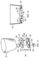
- FIGS. 5 and 6 detail the coupling between the facepiece 21 and the bag outlet 25.
- the facepiece 21 is attached to a valve plate assembly shown generally at 30 comprising an inner plate 31 and a outer plate 32, separated by a projection 35 and fused together using the known techniques of ultrasonic welding.
- the bag outlet 25 includes a protrusion 26 which fits inside a hole 33 of the outer plate 32.
- the hole 33 has a diameter or dimension (in the case of a non-circular opening) which is less than the outer extent of the protrusion 26, providing a secure fit upon attachment.
- the protrusion is a circumferential flange, spanning the full 360 degrees of the circumference of the bag outlet 25.
- the protrusion may comprise one or more tabs, each with arc segments of less than a total of 360 degrees.
- the outer edge of the protrusion may also include a protuberance 28 which serves as a "key way" to insure proper alignment of the bag with the facepiece.
- Inner plate 31 includes a hole 34 configured so as to be concentric with the outer plate hole 33.
- the facepiece valve plate assembly 30 accommodates an inhalation valve retainer 40 which fits inside the hole 34.
- the retainer 40 includes a radial barb fitting 41 which, in the preferred embodiment, extends circumferentially around the lower end of the retainer. This radial barb fitting 41 fits inside the inner diameter of bag outlet 25, and produces an interference fit and creates a fluid seal between the bag and the outer plate.
- the radial barb fitting 41 may also alternatively comprise one or more tabs, each with arc segments of less than a total of 360 degrees.
- the inhalation valve retainer 40 shown in cross-section in Figure 7, is designed to seat and retain an inhalation flapper valve 43.
- the flapper valve 43 permits the flow of oxygen from the reservoir bag 22 only during inhalation from the passenger and prevents exhalation into the bag, thus permitting maximum conservation of oxygen while ensuring passenger safety.
- the facepiece valve plate assembly 30 includes apertures which are adapted to retain an ambient inhalation valve 54 and an exhalation valve 52, both of which are typical in the prior art design.
- the passenger inhales a mixture of rarified ambient air and supplemental oxygen, which pass through each of their respective valves. The passenger then exhales through the exhalation valve.
- the connector assembly comprising the facepiece valve plate assembly 30, the bag outlet protrusion 26, and the radial barb fitting 41 of the retainer 40, are designed to provide a quick connecting and detachable securement for the assembly.
- the interference fit of this securement is sufficient so as to permit the connection to provide a fluid seal and withstand the required 89 N (20 pound) static tensile force applied during activation of oxygen flow by the passenger.
- this coupling does not require any complicated attachment configurations as are found in the prior art.
- This connection may be easily disengaged by maintenance personnel at appropriate intervals. In the present invention, the device may be more easily disassembled into its components.
Landscapes
- Health & Medical Sciences (AREA)
- Pulmonology (AREA)
- General Health & Medical Sciences (AREA)
- Business, Economics & Management (AREA)
- Emergency Management (AREA)
- Respiratory Apparatuses And Protective Means (AREA)
- Bag Frames (AREA)
- Separation Using Semi-Permeable Membranes (AREA)
- Aeration Devices For Treatment Of Activated Polluted Sludge (AREA)
- Farming Of Fish And Shellfish (AREA)
- External Artificial Organs (AREA)
- Air-Conditioning For Vehicles (AREA)
- Emergency Lowering Means (AREA)
Abstract
Description
- This invention relates to a continuous flow passenger oxygen dispensing unit of the type used on aircraft with pressurized cabins by passengers during decompression emergencies to provide supplemental oxygen. The present invention includes an integrally reinforced reservoir bag with an easily connectable and detachable coupling member, further including an airflow channel designed to prevent sticking while being collapsed during storage.
- Modern pressurized passenger aircraft fly at altitudes in the range of 5486 to 12192 m (18,000 to 40,000 feet). At these altitudes the air is at a reduced density because the atmospheric pressure is much lower than at sea level. Thus, the partial pressure of oxygen in the air is not sufficient to sustain normal respiration. Consequently, there has been a need for a system to supply additional oxygen for the survival of passengers in the event of a depressurization emergency of the airplane cabin.
- In the prior art, especially in U.S. Patent Nos. 4,098,271 and 4,832,017, there are shown emergency oxygen breathing apparatuses which each include a facepiece having valves, the facepiece designed to cover the nose and mouth and also is connected to an oxygen delivery tube. Connected between the facepiece and the delivery tube is a bag which functions as a reservoir, permitting an efficient use of the limited oxygen supply. In order to activate the flow of oxygen, the facepiece and bag assembly must be pulled down by the passenger; current specifications require that the assembly be capable of withstanding a static tensile force of not less than 89 N (20 pounds) for at least three seconds. In accordance with FAA requirements, these bags are made of a lightweight and resilient vinyl plastic material. However, such prior art bags in their current design cannot themselves withstand the 20 pound static tensile force without failure. The solution found in prior art systems is to insert within the bags a strain relief mechanism, typically a taut string, to withstand the tensile force.
- Figure 1 shows such a prior art system. This prior art (indicated generally at 10) includes a
facepiece 11,bag 12, and adelivery tube 13. The assembly is provided with astring 14, connected from the facepiece directly to the delivery tube in which the string functions as a strain relief mechanism. This strain relief mechanism is designed to withstand the 89 N (20 pound) static tensile force that would otherwise be applied to the bag. However, such prior art devices are difficult to manufacture and include extra materials and process steps resulting in additional time needed for the manufacture of the device, thus contributing to the expense. The prior art connectors joining the bag and facepiece are difficult to assemble and could not easily be assembled by maintenance personnel in the field. Further, the prior art connectors cannot withstand the 89 N (20 pound) static tensile force without a strain relief mechanism. As a result, it would be desirable to eliminate thestring 14 from the assembly. - One solution would be to select stronger materials which would produce an inherently stronger bag. However, other materials that could be used may be more flammable or entail increased weight and, therefore, cost. Consequently, such materials would need to undergo the long and costly process of being "requalified" in order to conform to FAA requirements. Therefore, it is not practical to use stronger bag materials as a substitute for the strain relief mechanism. Additionally, the prior art joint between the bag and the facepiece is not sufficient to withstand the required load.
- In the prior art systems, the delivery tube and facepiece connector have the strain relief mechanism attached to them and include additional securement which makes it difficult to easily replace a worn out bag. Consequently, the entire assembly is usually thrown away after a period of use, including facepieces which are still viable. It is an object of the present invention to provide a "quick connect" bag and facepiece that permits easy replacement of an old bag while retaining the facepiece, thus facilitating field changes of the bag resulting in reduced replacement expense and therefore greater efficiency for the airlines.
- In accordance with the present invention, there is a need to eliminate the strain relief mechanism while still providing resistance to the static tensile 89 N (20 pound) force. It is therefore a further object of the present invention to provide a bag which can withstand the static tensile 89 N (20 pound) force using qualified materials, but requiring fewer parts and manufacturing steps, resulting in a savings of time and money.
- The prior art assembly has the strain relief mechanism attached directly between the facepiece and the delivery tube so that there is no requirement for the joint between the bag and facepiece to withstand the static tensile 89 N (20 pound) force. It is still a further object of the present invention to provide a coupling between the bag and facepiece that is capable of withstanding the 89 N (20 pound) static tensile force while providing a fluid seal.
- In continuous flow passenger oxygen dispensing units, there was a risk that the reservoir bag may stick together during storage and restrict the outlet, thus blocking the oxygen flow during use. In the prior art, the strain relief mechanism assisted in preventing such blockage. Therefore, it is still another object of the present invention to provide a bag outlet that minimizes the potential for the neck of the bag to stick together without the use of the strain relief mechanism.
- The present invention relates to a continuous flow passenger oxygen dispensing unit which incorporates the above objects and includes a facepiece, a reservoir bag and a delivery tube. The reservoir bag is patterned with a reinforcing design in order to distribute the static tensile 89 N (20 pound) force across the width of the bag. The present connector assembly is also configured to withstand this force. The present connector is formed from a protrusion on the bag outlet which fits inside an aperture in the valve plate of the facepiece. This connection is sufficient to provide for quick and easy assembly to facilitate field changes. The present connector is integral with the reservoir bag outlet which is formed with serrations on its inner wall which assist in permitting oxygen passage in the event the walls of the outlet stick together during stowage.
-
- Figure 1 depicts the configuration of the prior art continuous flow passenger oxygen dispensing unit;
- Figure 2 depicts the configuration of the present continuous flow passenger oxygen dispensing unit;
- Figure 3 shows a front plan view of the preferred form of the reservoir bag contemplated by the present invention;
- Figure 4 shows a cross-section of the bag outlet along line 4-4 of Figure 3;
- Figure 5 shows an exploded view of the present facepiece and coupling mechanism;
- Figure 6 details an assembled cross-sectional view of the facepiece and coupling mechanism of the present invention;
- Figure 7 details a cross-section of the retainer assembly, including flapper valve;
- Figure 8 shows the retainer in a perspective view; and
- Figure 9 shows are assembled cross-sectional view of the facepiece along a line to detail the ambient inhalation and exhaust valves.
-
- In the present invention, shown generally at 20 in Figure 2, the
facepiece 21 is connected toreservoir bag 22, which in turn is connected to adelivery tube 23. As shown in Figures 2 and 3, the bag is manufactured with a strengthening pattern formed by directly fusing the vinyl film using the techniques of RF (radio frequency) welding, which are known in the art, for example, to weld seams. The pattern must be sufficient to distribute the static tensile 89 N (20 pound) force over the width of the bag, thus eliminating the need for a discrete strain relief mechanism. The pattern is designed to distribute the vertically-applied force in a horizontal direction along the bag, to the left and right. The specific design of the pattern is not critical, but it must incorporate certain factors: force is distributed by thewelds 24 and these must be of a sufficient width with sufficient distances between each weld; also, slanting thewelds 24 at an angle (as show in figures 2 and 3) helps distribute the force. Most importantly, however, are the welds where thedelivery tube 23 joins thebag 22 and also where theoutlet 25 joins thebag 22. These welds bear a significant portion of the force. As a means of securement, thedelivery tube 23 is also attached to thebag 22 using RF welds. As an additional benefit of the present invention, the prior art vinyl film may still be used, and new materials, which would require requalification, are not needed. - As shown in Figures 2, 3, 4 and 5, the bag includes a
cylindrical outlet 25 which is connected to thefacepiece 21, with theoutlet 25 including a serratedinner surface 27. Theserrated surface 27 minimizes any sticking and also provides flow channels if thebag outlet 25 is collapsed and the walls stick together when stowed in an aircraft compartment for a period of up to three years. In the event of outlet collapse, the area of contact between opposing sidewalls will be minimal. The design may also include inverted U-shaped scallops (not shown) which are found at the base of theoutlet 25 and permit oxygen flow to the sides of the scallops in the event of outlet collapse. As a result, this design permits the oxygen to flow in the event of activation during a decompression emergency. - Figures 5 and 6 detail the coupling between the
facepiece 21 and thebag outlet 25. Thefacepiece 21 is attached to a valve plate assembly shown generally at 30 comprising aninner plate 31 and aouter plate 32, separated by aprojection 35 and fused together using the known techniques of ultrasonic welding. Thebag outlet 25 includes aprotrusion 26 which fits inside ahole 33 of theouter plate 32. Thehole 33 has a diameter or dimension (in the case of a non-circular opening) which is less than the outer extent of theprotrusion 26, providing a secure fit upon attachment. In the preferred embodiment, the protrusion is a circumferential flange, spanning the full 360 degrees of the circumference of thebag outlet 25. However, the protrusion may comprise one or more tabs, each with arc segments of less than a total of 360 degrees. As seen in Fig. 4, the outer edge of the protrusion may also include aprotuberance 28 which serves as a "key way" to insure proper alignment of the bag with the facepiece.Inner plate 31 includes ahole 34 configured so as to be concentric with theouter plate hole 33. The facepiecevalve plate assembly 30 accommodates aninhalation valve retainer 40 which fits inside thehole 34. Theretainer 40 includes a radial barb fitting 41 which, in the preferred embodiment, extends circumferentially around the lower end of the retainer. This radial barb fitting 41 fits inside the inner diameter ofbag outlet 25, and produces an interference fit and creates a fluid seal between the bag and the outer plate. The radial barb fitting 41 may also alternatively comprise one or more tabs, each with arc segments of less than a total of 360 degrees. Theinhalation valve retainer 40, shown in cross-section in Figure 7, is designed to seat and retain aninhalation flapper valve 43. Theflapper valve 43 permits the flow of oxygen from thereservoir bag 22 only during inhalation from the passenger and prevents exhalation into the bag, thus permitting maximum conservation of oxygen while ensuring passenger safety. - As shown in Figure 9, the facepiece
valve plate assembly 30 includes apertures which are adapted to retain anambient inhalation valve 54 and anexhalation valve 52, both of which are typical in the prior art design. During use, the passenger inhales a mixture of rarified ambient air and supplemental oxygen, which pass through each of their respective valves. The passenger then exhales through the exhalation valve. - The connector assembly, comprising the facepiece
valve plate assembly 30, thebag outlet protrusion 26, and the radial barb fitting 41 of theretainer 40, are designed to provide a quick connecting and detachable securement for the assembly. The interference fit of this securement is sufficient so as to permit the connection to provide a fluid seal and withstand the required 89 N (20 pound) static tensile force applied during activation of oxygen flow by the passenger. However, this coupling does not require any complicated attachment configurations as are found in the prior art. This connection may be easily disengaged by maintenance personnel at appropriate intervals. In the present invention, the device may be more easily disassembled into its components. These components, such as thebag assembly 22 which has a relatively short useful life, may be easily detached from the components with a longer useful life, such as thefacepiece 21. The present coupling may permit a longer useful life for the various components of the system than had been capable previously in the prior art. - The foregoing description is that of the preferred embodiment of the invention. Various changes and modifications may be made by persons of ordinary skill in the art without departing from spirit and scope of the invention as defined in the appended claims.
Claims (8)
- A continuous flow passenger oxygen dispensing unit (20) for providing supplemental oxygen in the event of loss of cabin pressure in a pressurized aircraft comprising a facepiece (21) for introducing oxygen to the nose and mouth of a passenger, a bag (22) attached to said facepiece (21) and having a delivery tube (23) attached to said bag (22) and adapted to be connected to an oxygen supply system, said bag (22) having an enclosed volume to act as a reservoir for oxygen for breathing by a passenger, characterized by:said bag (22) having an outlet (25) extending therefrom for delivery of oxygen into said facepiece (21) and a protrusion (26) formed integrally on said outlet (25) of said bag (22) which is received through an aperture (33) in said facepiece (21) having a diameter less than the outer extent of said protrusion (26); anda retainer (40) in the form of a separate discrete element received within said outlet (25) in said bag (22) to hold said protrusion (26) of said bag outlet (25) in an easily assembled connection between said facepiece (21) and said bag (22), said connection between said bag (22) and facepiece (21) also adapted to provide a fluid seal and withstand at least a static tensile 89 N (20 pound) force.
- A continuous flow passenger oxygen dispensing unit (20) as claimed in claim 1 wherein said bag (22) is formed of a lightweight vinyl film with a reinforcing pattern (24) composed of fused portions of the walls of the bag (22) for distributing a static tensile 89 N (20 pound) force across the width of said bag.
- A continuous flow passenger oxygen dispensing unit (20) as claimed in claim 2 wherein said pattern (24) is formed in said bag (22) using RF welding.
- A continuous flow passenger oxygen dispensing unit (20) as claimed in claim 1 wherein said facepiece (21) comprises a valve plate assembly (30) further comprising an inner plate (31) and an outer plate (32) which are secured to each other and to side walls of the facepiece (21) to form the facepiece's bottom.
- A continuous flow passenger oxygen dispensing unit (20) as claimed in claim 4 wherein said aperture (33) which receives said bag is in said valve plate assembly (30).
- A continuous flow passenger oxygen dispensing unit (20) as claimed in claim 1 wherein said retainer (40) further comprises a flapper valve assembly (43).
- A continuous flow passenger oxygen dispensing unit (20) as claimed in claim 1 wherein said retainer (40) includes a radial barb (41) fitting which extends circumferentially around an edge of said retainer (40) in order to produce an interference fit and fluid seal between said bag outlet (25) and said retainer (40).
- A continuous flow passenger oxygen dispensing unit (20) as claimed in claim 1 wherein said outlet (25) of said bag (22) comprises a cylindrical outlet (25) with a serrated inner surface (27) for preventing the collapse and inadvertent sealing of said outlet (25) during storage.
Applications Claiming Priority (3)
| Application Number | Priority Date | Filing Date | Title |
|---|---|---|---|
| US08/048,783 US5408995A (en) | 1993-04-16 | 1993-04-16 | Continuous flow passenger oxygen dispensing unit |
| US48783 | 1993-04-16 | ||
| PCT/US1994/003869 WO1994023796A1 (en) | 1993-04-16 | 1994-04-08 | Continuous flow passenger oxygen dispensing unit |
Publications (3)
| Publication Number | Publication Date |
|---|---|
| EP0702581A1 EP0702581A1 (en) | 1996-03-27 |
| EP0702581A4 EP0702581A4 (en) | 1996-04-03 |
| EP0702581B1 true EP0702581B1 (en) | 2000-06-21 |
Family
ID=21956425
Family Applications (1)
| Application Number | Title | Priority Date | Filing Date |
|---|---|---|---|
| EP94913387A Expired - Lifetime EP0702581B1 (en) | 1993-04-16 | 1994-04-08 | Continuous flow passenger oxygen dispensing unit |
Country Status (8)
| Country | Link |
|---|---|
| US (1) | US5408995A (en) |
| EP (1) | EP0702581B1 (en) |
| AT (1) | ATE193979T1 (en) |
| AU (1) | AU6556694A (en) |
| BR (1) | BR9405866A (en) |
| CA (1) | CA2159996C (en) |
| DE (1) | DE69424994T2 (en) |
| WO (1) | WO1994023796A1 (en) |
Families Citing this family (15)
| Publication number | Priority date | Publication date | Assignee | Title |
|---|---|---|---|---|
| US6016804A (en) * | 1997-10-24 | 2000-01-25 | Scott Technologies, Inc. | Respiratory mask and method of making thereof |
| AU744319B2 (en) | 1997-10-24 | 2002-02-21 | Scott Technologies, Inc. | Respiratory mask and method of making thereof |
| SE9802123D0 (en) * | 1998-06-15 | 1998-06-15 | Siemens Elema Ab | directional valve |
| US6352077B1 (en) * | 2000-05-01 | 2002-03-05 | Tilak M. Shah | Film welded reservoir bag for breathing circuit and method of making the same |
| US6347401B1 (en) | 2001-05-15 | 2002-02-19 | John Joyce | Face piece protection system |
| FR2832639B1 (en) * | 2001-11-28 | 2004-07-02 | Intertechnique Sa | METHOD AND DEVICE FOR PROTECTING PASSENGERS OF AN AIRCRAFT AGAINST HYPOXIA |
| US20040084048A1 (en) * | 2002-09-27 | 2004-05-06 | Alex Stenzler | High FIO2 oxygen mask with a sequential dilution feature and filter |
| JP4834000B2 (en) * | 2005-01-13 | 2011-12-07 | エイヴォックス システムズ インコーポレイテッド | Device for deploying an oxygen mask |
| DE102006025725B4 (en) * | 2006-05-31 | 2011-07-07 | B/E Aerospace Systems GmbH, 23560 | Passenger Oxygen Mask |
| EP2168623B1 (en) * | 2008-09-26 | 2011-09-21 | General Electric Company | Arrangement for detecting a leak in anesthesia system |
| DE102013206181B4 (en) * | 2013-04-09 | 2016-12-01 | B/E Aerospace Systems Gmbh | Passenger oxygen mask and breathing bag for an oxygen mask |
| US11338158B2 (en) * | 2018-03-15 | 2022-05-24 | Safran Aerotechnics Sas | System and a method for delivering breathing gas to passengers on-board an aircraft |
| US20220062667A1 (en) * | 2020-08-28 | 2022-03-03 | B/E Aerospace, Inc. | Oxygen Mask And System |
| EP4056236A1 (en) * | 2021-03-11 | 2022-09-14 | B/E Aerospace Systems GmbH | Oxygen mask for use in an aircraft, emergency oxygen system, and aircraft |
| EP4074381B1 (en) * | 2021-04-14 | 2025-12-10 | B/E Aerospace Systems GmbH | Passenger oxygen mask for use in an aircraft, emergency oxygen system, and aircraft |
Family Cites Families (15)
| Publication number | Priority date | Publication date | Assignee | Title |
|---|---|---|---|---|
| US3137296A (en) * | 1961-05-29 | 1964-06-16 | Electric Storage Battery Co | Respirator filter mounting means |
| US3347566A (en) * | 1964-10-26 | 1967-10-17 | Scott Aviation Corp | Breakaway coupling assembly |
| US3357426A (en) * | 1965-01-14 | 1967-12-12 | Univ California | Adherent face mask having a quick disconnect fitting and disposable components |
| US3486730A (en) * | 1966-08-18 | 1969-12-30 | Us Army | Quick disconnect coupling and valve combination |
| US4098271A (en) * | 1975-09-29 | 1978-07-04 | Mcdonnell Douglas Corporation | Oxygen supply system and flow indicator |
| DE2609034B2 (en) * | 1976-03-05 | 1981-04-30 | Drägerwerk AG, 2400 Lübeck | Connection for breathing apparatus |
| US4488546A (en) * | 1983-06-23 | 1984-12-18 | Bernhardt Apparatebau Gmbh & Co. | Release mechanism for retention means for oxygen masks |
| US4559939A (en) * | 1984-02-13 | 1985-12-24 | Lockheed Corporation | Compatible smoke and oxygen masks for use on aircraft |
| DE3610493A1 (en) * | 1986-03-27 | 1987-10-01 | Draegerwerk Ag | BREATHING MASK MADE OF AN ELASTIC MOLDED BODY |
| DE3613814A1 (en) * | 1986-04-24 | 1987-10-29 | Draegerwerk Ag | EMERGENCY SUPPLY UNIT WITH A BREATHING UNIT |
| US5002050A (en) * | 1986-09-17 | 1991-03-26 | Mcginnis Gerald E | Medical gas flow control valve, system and method |
| US4869245A (en) * | 1986-10-20 | 1989-09-26 | Conax Florida Corporation | Automatic release mechanism for a breathing mask |
| US4865027A (en) * | 1988-09-27 | 1989-09-12 | The University Of Michigan | Non-rebreathing collapsible chamber continuous aerosol delivery system with infusion port |
| DK160130C (en) * | 1988-11-04 | 1991-07-15 | Ambu Int As | SINGLE USE RESUSCITATOR |
| US5265597A (en) * | 1992-07-01 | 1993-11-30 | Puritan-Bennett Corporation | Passenger oxygen mask having a plurality of fingers and recesses for mounting the mask to an oxygen bag |
-
1993
- 1993-04-16 US US08/048,783 patent/US5408995A/en not_active Expired - Lifetime
-
1994
- 1994-04-08 DE DE69424994T patent/DE69424994T2/en not_active Expired - Fee Related
- 1994-04-08 BR BR9405866A patent/BR9405866A/en not_active IP Right Cessation
- 1994-04-08 AT AT94913387T patent/ATE193979T1/en active
- 1994-04-08 CA CA002159996A patent/CA2159996C/en not_active Expired - Fee Related
- 1994-04-08 WO PCT/US1994/003869 patent/WO1994023796A1/en not_active Ceased
- 1994-04-08 AU AU65566/94A patent/AU6556694A/en not_active Abandoned
- 1994-04-08 EP EP94913387A patent/EP0702581B1/en not_active Expired - Lifetime
Also Published As
| Publication number | Publication date |
|---|---|
| AU6556694A (en) | 1994-11-08 |
| ATE193979T1 (en) | 2000-07-15 |
| CA2159996C (en) | 2003-06-17 |
| DE69424994D1 (en) | 2000-07-27 |
| DE69424994T2 (en) | 2000-10-26 |
| BR9405866A (en) | 1995-12-05 |
| WO1994023796A1 (en) | 1994-10-27 |
| EP0702581A1 (en) | 1996-03-27 |
| CA2159996A1 (en) | 1994-10-27 |
| EP0702581A4 (en) | 1996-04-03 |
| US5408995A (en) | 1995-04-25 |
Similar Documents
| Publication | Publication Date | Title |
|---|---|---|
| US5408995A (en) | Continuous flow passenger oxygen dispensing unit | |
| US4622964A (en) | Valve for breathing device | |
| EP0070317B1 (en) | Life support system and method of providing fresh air to enclosed areas | |
| US6523539B2 (en) | Self-elongating oxygen hose for stowable aviation crew oxygen mask | |
| US4559939A (en) | Compatible smoke and oxygen masks for use on aircraft | |
| CN110270023B (en) | System and method for delivering breathing gas to passengers on an aircraft | |
| US4974584A (en) | Emergency air supply assembly for trapped fire fighters | |
| US5640952A (en) | Personal emergency breathing system for supplied air respirators | |
| US5265597A (en) | Passenger oxygen mask having a plurality of fingers and recesses for mounting the mask to an oxygen bag | |
| US4625721A (en) | Smoke mask | |
| US20210121649A1 (en) | Portable rebreathing system with staged addition of oxygen enrichment | |
| CN104520190B (en) | Aircraft lavatory emergency oxygen device | |
| EP0695561A1 (en) | Breathing equipment | |
| US8474456B2 (en) | Oxygen breathing mask | |
| US10525223B2 (en) | Bag-valve-mask | |
| US3467093A (en) | Oxygen mask and valve structure | |
| US20070240720A1 (en) | Supplemental passenger oxygen mask | |
| EP0276217B1 (en) | Breathing apparatus | |
| EP0197641B1 (en) | Decompression and toxic fume protection apparatus | |
| CA2019198C (en) | Emergency air supply assembly for trapped fire fighters | |
| EP3791933B1 (en) | System for delivering breathing gas to passengers | |
| WO2007088330A1 (en) | Resuscitator arrangements and filter assemblies | |
| WO1989002293A1 (en) | Breathing apparatus | |
| JONES et al. | Respiratory System Particularly Suited for Aircrew Use(Patent) |
Legal Events
| Date | Code | Title | Description |
|---|---|---|---|
| PUAI | Public reference made under article 153(3) epc to a published international application that has entered the european phase |
Free format text: ORIGINAL CODE: 0009012 |
|
| 17P | Request for examination filed |
Effective date: 19951019 |
|
| AK | Designated contracting states |
Kind code of ref document: A1 Designated state(s): AT BE CH DE DK ES FR GB GR IE IT LI LU MC NL PT SE |
|
| A4 | Supplementary search report drawn up and despatched |
Effective date: 19960221 |
|
| AK | Designated contracting states |
Kind code of ref document: A4 Designated state(s): AT BE CH DE DK ES FR GB GR IE IT LI LU MC NL PT SE |
|
| 17Q | First examination report despatched |
Effective date: 19981014 |
|
| GRAG | Despatch of communication of intention to grant |
Free format text: ORIGINAL CODE: EPIDOS AGRA |
|
| RAP1 | Party data changed (applicant data changed or rights of an application transferred) |
Owner name: SCOTT TECHNOLOGIES, INC. |
|
| GRAG | Despatch of communication of intention to grant |
Free format text: ORIGINAL CODE: EPIDOS AGRA |
|
| GRAH | Despatch of communication of intention to grant a patent |
Free format text: ORIGINAL CODE: EPIDOS IGRA |
|
| GRAH | Despatch of communication of intention to grant a patent |
Free format text: ORIGINAL CODE: EPIDOS IGRA |
|
| GRAA | (expected) grant |
Free format text: ORIGINAL CODE: 0009210 |
|
| AK | Designated contracting states |
Kind code of ref document: B1 Designated state(s): AT BE CH DE DK ES FR GB GR IE IT LI LU MC NL PT SE |
|
| PG25 | Lapsed in a contracting state [announced via postgrant information from national office to epo] |
Ref country code: NL Free format text: LAPSE BECAUSE OF FAILURE TO SUBMIT A TRANSLATION OF THE DESCRIPTION OR TO PAY THE FEE WITHIN THE PRESCRIBED TIME-LIMIT Effective date: 20000621 Ref country code: LI Free format text: LAPSE BECAUSE OF FAILURE TO SUBMIT A TRANSLATION OF THE DESCRIPTION OR TO PAY THE FEE WITHIN THE PRESCRIBED TIME-LIMIT Effective date: 20000621 Ref country code: IT Free format text: LAPSE BECAUSE OF FAILURE TO SUBMIT A TRANSLATION OF THE DESCRIPTION OR TO PAY THE FEE WITHIN THE PRE;WARNING: LAPSES OF ITALIAN PATENTS WITH EFFECTIVE DATE BEFORE 2007 MAY HAVE OCCURRED AT ANY TIME BEFORE 2007. THE CORRECT EFFECTIVE DATE MAY BE DIFFERENT FROM THE ONE RECORDED.SCRIBED TIME-LIMIT Effective date: 20000621 Ref country code: GR Free format text: LAPSE BECAUSE OF NON-PAYMENT OF DUE FEES Effective date: 20000621 Ref country code: ES Free format text: THE PATENT HAS BEEN ANNULLED BY A DECISION OF A NATIONAL AUTHORITY Effective date: 20000621 Ref country code: CH Free format text: LAPSE BECAUSE OF FAILURE TO SUBMIT A TRANSLATION OF THE DESCRIPTION OR TO PAY THE FEE WITHIN THE PRESCRIBED TIME-LIMIT Effective date: 20000621 Ref country code: BE Free format text: LAPSE BECAUSE OF FAILURE TO SUBMIT A TRANSLATION OF THE DESCRIPTION OR TO PAY THE FEE WITHIN THE PRESCRIBED TIME-LIMIT Effective date: 20000621 Ref country code: AT Free format text: LAPSE BECAUSE OF FAILURE TO SUBMIT A TRANSLATION OF THE DESCRIPTION OR TO PAY THE FEE WITHIN THE PRESCRIBED TIME-LIMIT Effective date: 20000621 |
|
| REF | Corresponds to: |
Ref document number: 193979 Country of ref document: AT Date of ref document: 20000715 Kind code of ref document: T |
|
| REG | Reference to a national code |
Ref country code: CH Ref legal event code: EP |
|
| REG | Reference to a national code |
Ref country code: IE Ref legal event code: FG4D |
|
| REF | Corresponds to: |
Ref document number: 69424994 Country of ref document: DE Date of ref document: 20000727 |
|
| ET | Fr: translation filed | ||
| PG25 | Lapsed in a contracting state [announced via postgrant information from national office to epo] |
Ref country code: SE Free format text: LAPSE BECAUSE OF FAILURE TO SUBMIT A TRANSLATION OF THE DESCRIPTION OR TO PAY THE FEE WITHIN THE PRESCRIBED TIME-LIMIT Effective date: 20000921 Ref country code: PT Free format text: LAPSE BECAUSE OF FAILURE TO SUBMIT A TRANSLATION OF THE DESCRIPTION OR TO PAY THE FEE WITHIN THE PRESCRIBED TIME-LIMIT Effective date: 20000921 Ref country code: DK Free format text: LAPSE BECAUSE OF FAILURE TO SUBMIT A TRANSLATION OF THE DESCRIPTION OR TO PAY THE FEE WITHIN THE PRESCRIBED TIME-LIMIT Effective date: 20000921 |
|
| NLV1 | Nl: lapsed or annulled due to failure to fulfill the requirements of art. 29p and 29m of the patents act | ||
| REG | Reference to a national code |
Ref country code: CH Ref legal event code: PL |
|
| PG25 | Lapsed in a contracting state [announced via postgrant information from national office to epo] |
Ref country code: LU Free format text: LAPSE BECAUSE OF NON-PAYMENT OF DUE FEES Effective date: 20010408 |
|
| PG25 | Lapsed in a contracting state [announced via postgrant information from national office to epo] |
Ref country code: IE Free format text: LAPSE BECAUSE OF NON-PAYMENT OF DUE FEES Effective date: 20010409 |
|
| PLBE | No opposition filed within time limit |
Free format text: ORIGINAL CODE: 0009261 |
|
| STAA | Information on the status of an ep patent application or granted ep patent |
Free format text: STATUS: NO OPPOSITION FILED WITHIN TIME LIMIT |
|
| PG25 | Lapsed in a contracting state [announced via postgrant information from national office to epo] |
Ref country code: MC Free format text: LAPSE BECAUSE OF NON-PAYMENT OF DUE FEES Effective date: 20010430 |
|
| 26N | No opposition filed | ||
| REG | Reference to a national code |
Ref country code: GB Ref legal event code: IF02 |
|
| REG | Reference to a national code |
Ref country code: IE Ref legal event code: MM4A |
|
| REG | Reference to a national code |
Ref country code: GB Ref legal event code: 732E |
|
| REG | Reference to a national code |
Ref country code: FR Ref legal event code: TP Ref country code: FR Ref legal event code: CD |
|
| PGFP | Annual fee paid to national office [announced via postgrant information from national office to epo] |
Ref country code: FR Payment date: 20090414 Year of fee payment: 16 Ref country code: DE Payment date: 20090422 Year of fee payment: 16 |
|
| PGFP | Annual fee paid to national office [announced via postgrant information from national office to epo] |
Ref country code: GB Payment date: 20090421 Year of fee payment: 16 |
|
| GBPC | Gb: european patent ceased through non-payment of renewal fee |
Effective date: 20100408 |
|
| REG | Reference to a national code |
Ref country code: FR Ref legal event code: ST Effective date: 20101230 |
|
| PG25 | Lapsed in a contracting state [announced via postgrant information from national office to epo] |
Ref country code: DE Free format text: LAPSE BECAUSE OF NON-PAYMENT OF DUE FEES Effective date: 20101103 |
|
| PG25 | Lapsed in a contracting state [announced via postgrant information from national office to epo] |
Ref country code: GB Free format text: LAPSE BECAUSE OF NON-PAYMENT OF DUE FEES Effective date: 20100408 |
|
| PG25 | Lapsed in a contracting state [announced via postgrant information from national office to epo] |
Ref country code: FR Free format text: LAPSE BECAUSE OF NON-PAYMENT OF DUE FEES Effective date: 20100430 |