EP0702472A1 - A method and an apparatus for shaping the output traffic in a fixed length cell switching network node - Google Patents
A method and an apparatus for shaping the output traffic in a fixed length cell switching network node Download PDFInfo
- Publication number
- EP0702472A1 EP0702472A1 EP94480086A EP94480086A EP0702472A1 EP 0702472 A1 EP0702472 A1 EP 0702472A1 EP 94480086 A EP94480086 A EP 94480086A EP 94480086 A EP94480086 A EP 94480086A EP 0702472 A1 EP0702472 A1 EP 0702472A1
- Authority
- EP
- European Patent Office
- Prior art keywords
- calendar
- traffic
- entry
- entries
- user
- Prior art date
- Legal status (The legal status is an assumption and is not a legal conclusion. Google has not performed a legal analysis and makes no representation as to the accuracy of the status listed.)
- Withdrawn
Links
Images


Classifications
-
- H—ELECTRICITY
- H04—ELECTRIC COMMUNICATION TECHNIQUE
- H04L—TRANSMISSION OF DIGITAL INFORMATION, e.g. TELEGRAPHIC COMMUNICATION
- H04L12/00—Data switching networks
- H04L12/54—Store-and-forward switching systems
- H04L12/56—Packet switching systems
- H04L12/5601—Transfer mode dependent, e.g. ATM
- H04L12/5602—Bandwidth control in ATM Networks, e.g. leaky bucket
-
- H—ELECTRICITY
- H04—ELECTRIC COMMUNICATION TECHNIQUE
- H04Q—SELECTING
- H04Q11/00—Selecting arrangements for multiplex systems
- H04Q11/04—Selecting arrangements for multiplex systems for time-division multiplexing
- H04Q11/0428—Integrated services digital network, i.e. systems for transmission of different types of digitised signals, e.g. speech, data, telecentral, television signals
- H04Q11/0478—Provisions for broadband connections
-
- H—ELECTRICITY
- H04—ELECTRIC COMMUNICATION TECHNIQUE
- H04L—TRANSMISSION OF DIGITAL INFORMATION, e.g. TELEGRAPHIC COMMUNICATION
- H04L12/00—Data switching networks
- H04L12/54—Store-and-forward switching systems
- H04L12/56—Packet switching systems
- H04L12/5601—Transfer mode dependent, e.g. ATM
- H04L2012/5678—Traffic aspects, e.g. arbitration, load balancing, smoothing, buffer management
- H04L2012/5679—Arbitration or scheduling
-
- H—ELECTRICITY
- H04—ELECTRIC COMMUNICATION TECHNIQUE
- H04L—TRANSMISSION OF DIGITAL INFORMATION, e.g. TELEGRAPHIC COMMUNICATION
- H04L12/00—Data switching networks
- H04L12/54—Store-and-forward switching systems
- H04L12/56—Packet switching systems
- H04L12/5601—Transfer mode dependent, e.g. ATM
- H04L2012/5678—Traffic aspects, e.g. arbitration, load balancing, smoothing, buffer management
- H04L2012/568—Load balancing, smoothing or shaping
Definitions
- This invention deals with problems of traffic control in the fixed length cells switching high speed networks and more particularly with a shaping method and apparatus to be implemented in an ATM network node adapter.
- ATM Asynchronous Transfer Mode
- Congestion control inside these networks is one of the major problems to be resolved.
- the cells are short, no space is allocated in the header to enable error recovery for the cell payload. If one cell of the block has been lost or discarded by the network in case of network congestion, error recovery is performed at the higher-level by recovery protocols retransmitting the user data block.
- the error rate being extremely low in the internode links, cells lost because of random errors is not a potential problem.
- a node discards cells for reason of traffic congestion detected, it is unlikely that these cells will come from a small number of logical data blocks. Discarding 1000 cells, if the average user data blocks length is 2KBytes(a low estimate), sent as 43 cells, may cause the network to absorb a retransmission of 43,000 cells! This case indeed is the worse case when the 1000 messages come from 1000 different connections. That is why the protocols need to be efficient enough to limit the congestion problems in this type of networks.
- the end-to-end traffic of data for one user, between the source and the destination is represented by a Virtual Connection (VC); several Virtual Connections may be grouped in a Virtual Path (VP) that can be switched as a unit.
- the bandwidth is allocated dynamically as part of a connection setup signalling procedure that precedes end-to-end information exchange.
- the source user provides, in addition to the destination point, a set of parameters, called the traffic descriptors, which attempts to describe the traffic that will be generated onto the links. For instance, a mandatory descriptor is the peak cell rate of the connection, R.
- Constant Bit Rate (CBR) connections i.e., periodic stream of cells such as uncompressed voice
- VBR Variable Bit Rate
- the burst of traffic is measured by the average cell rate and the average duration of an emission at the peak rate R in most of the high speed networks literature.
- CBR Constant Bit Rate
- VBR Variable Bit Rate
- the delay can be acceptable but not the cell loss. That's why the network guarantees a Quality of Service (QoS).
- QoS Quality of Service
- the QoS guaranteed by a network is, in most cases, expressed in terms of cell loss probability and maximum end-to-end delay for a cell, independently of network topologies and protocols.
- the end-to-end delay between two users is increased if the end-to-end connection crosses different network entities (private or public carrier networks) which have their own protocols and traffic management.
- the network nodes In order to meet the QoS, the network nodes have to control the traffic congestion both at connection admission time and once the connections established.
- the access node At connection admission time the access node has to decide if it can accept the connection or not: its decision is based on the actual load of the links, and its analyzing of the traffic parameters of the connection. Moreover, it has also to compute a path table to carry this overload of traffic through the different nodes. If no path is found, the call is rejected. It is important to note that the decision to accept a new call has to be taken not only if the network node estimates that the QoS for the connection will be met but also if it is sure that the added traffic will not have a significant impact on the QoS of all the connections already established.
- a first control on traffic congestion, once the connection is established, is performed by the policing function implemented in a device, the policer, of the network access node adapter.
- the policer will detect and penalize the violation of the peak cell rate on the current traffic compared to the one required at call set up.
- another descriptor such as the Sustainable Cell Rate, the SCR (that is not yet a standardized parameter) can be used as a criterion for the policing function; in the following of the description, any reference to the peak cell rate can be replaced by SCR.
- the policing function is also referred in the ATM literature as the Network Parameter Control (NPC) or the Usage Parameter Control (UPC) depending if the source unit is a Network Node or a Customer Premise Node; Indeed, an efficient policing function should be transparent as long as the traffic characteristics provided by the source at call setup are met. When the number of cells received exceeds the number of cells corresponding to the peak rate negotiated at traffic establishment time, the policing function will discard or tag the user cells depending on the cell loss priority.
- NPC Network Parameter Control
- UPC Usage Parameter Control
- a second control of traffic congestion consists in shaping the output network node traffic by spacing the cells departures in such a way that the time between two departures of cells for a same connection is never below the minimal value negotiated at connection setup time. It has been shown that, on the average, the multiplexing of spaced cells tends to decrease the 'burstiness' of the aggregate traffic and then allows a better utilization of the network resources.
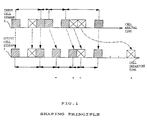
- FIG.1 shows the shaping principle applied to the input cells stream 1.
- the shaded cells have been sent by a first user and the cells marked with a cross have been sent by a second user.
- the spacing of the cells is done in respect with the bandwidth share required by the users: in the output cells stream, the departure time between two cells is smaller for the cells of the first user than for the second user because the first user has required a greater bandwidth share than the second user; moreover, in the output stream the bursts of traffic have decreased: one can note that the groups of three cells of the input stream 1 have disappeared in the output stream 2.
- the policing function is implemented in the access network nodes.
- the device implementing the policing function, the policer is part of the high speed adapter cards; it controls and, if necessary, penalizes the traffic entering the network.
- the shaping function is implemented in the devices accessing a network: they can be Customer Premise Nodes accessing an ATM network or a Network Node at the boundary of a first ATM network and intending to access another ATM network.
- the device implementing the shaping function, the shaper is also part of the high speed adapter cards and controls the sending of the output traffic cells.
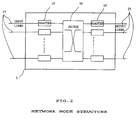
- FIG.2 shows a shaper and a policer implemented in a network node.
- FIG. 15 are the input lines conveying the input cells streams which are received by the input adapters 10; in each input adapter 10 the policer controls and penalizes, if necessary, the cells stream for each user; than the cells are switched in the switch 30 and sent to the output adapters 20.
- each output adapter 20 there is a shaper which spaces the cells which are sent to the output lines 25.
- FIG.3 shows a network topology to convey the traffic of users from the source unit 40 to the destination unit 60 through the two networks 42 and 52.
- the nodes 45 are the access nodes; the policers are implemented in these access nodes 45.
- the shapers are implemented in the source unit 40 and in the node 50 which is at the boundary of the first network 42 and which accesses the second network 52.
- the destination unit 60 may be a Customer Premise Node having implemented a policer, it is recommended to implement also a shaper in the node 55 located at the boundary of the network 52.
- each policing function estimates one or more traffic parameters for a given period of time P. As this period of time P decreases, the policer may become non-transparent to users generating a traffic in conformance with the parameters negotiated at connection establishment time. On the other hand, as P increases, the policer takes longer to detect that the source exceeds its declared characteristics. However, the latter approach is more fair since it allows the user to generate a stream of cells that have short-term fluctuations. This is done at the expense of more memory requirements at the node level.
- T corresponds to the inverse of the peak cell rate R
- ⁇ tolerance
- the policer discards cells not only because the source of traffic has violated the parameters negotiated at connection establishment but also because of a distorsion in the cell stream well known as jitter or Cell Delay Variation (CDV).
- CDV Cell Delay Variation
- This distorsion is due to the queuing of the cells at each intermediate network node and more generally the multiplexing of the cells on the output lines.
- the magnitude of the jitter depends on many parameters: the connection peak rate, the peak rate of the other connections that share the same link, the link load, the number of nodes passed through etc...A consequence of the jitter is to induce, as the user cells travel through the network, some distortion on the traffic parameters declared by the source upstream.
- the instantaneous peak cell rate R' which may be modified and may pass beyond the value R declared by the source upstream at connection establishment time.
- R'>R and the policing function with a short measurement interval (small period of time P) may take undesirable discarding actions.
- This is typically the case of the GCRA when the specified tolerance ⁇ , named Cell Delay Variation Tolerance (CDVT), is small. That's why the shaping function will buffer cells so that the departure rate from a node is less that the arrival rate. It has been shown that the multiplexing of spaced cells tends to decrease the "burstiness" of the aggregate traffic and then allows a better utilization of the network resources.
- CDVT Cell Delay Variation Tolerance
- Policing and shaping control techniques should take into account the real-time constraints; as implemented in high speed network node adapters dealing with lines at several hundreds of Megabits per second.
- the cell transmission time (cell time cycle) is about 2.7 ⁇ s for a line speed of 155.52 Mbps (OC-3), and less than 0.7 ⁇ s for a line speed of 622.08 Mbps (OC-12). This implies that the shaping and policing methods have a very short computing time not to pass the cell cycle.
- the first one relies on a very basic principle: the shaping function sends a given number, p, of cells at the link speed C, and keeps “silent” (i.e. the cells are buffered) till p(C/R-1). If this approach requires no computation nor complex operations at the cell level, the CDV induced is quite bad and the tolerance that should be accommodated at the GRCA level to accept all the cells would be typically p(C/R-1).
- a new entry of the calendar is seek at each cell time cycle, and the list-of-cells that have to be sent at time tn (0 ⁇ n ⁇ N) if any, is moved and queued to an output list.
- the following operations are done at each cell time cycle:
- the object of this present invention is to provide in the network node adapters transporting fixed length cells, a shaping method which controls and minimizes the CDV with a minimum of computing resources. This would limit the bursts of traffic and thus the problem of traffic congestion in these high speed networks. This invention would also allow to anticipate the real traffic and thus avoid any penalization of the policers when accessing another network.
- the shaping method of the invention implemented in the adapter supporting output lines consists in scheduling in advance the departure time of the cells for each transfer of traffic between a source unit and a destination unit.
- the shaping function is activated each time a change has occured in the traffic supported (new traffic added, end of traffic, modification in the traffic already established). This anticipated computing reduces significantly the number of operations performed in the cell cycle to send a cell onto an output line.
- the method provides two lookup tables called the active and the standby calendars per one output line of the adapter, each entry in the calendars storing a traffic identifier representing the position of one cell in the output cell stream which will be read by the transmit device and sent onto the output line;
- the standby calendar is filled up with the new output stream and once the standby calendar is filled up it becomes the active one; the active calendar is continuously read and the transmit device is activated at each entry read to send onto the output line the cell corresponding to the traffic identifier read.
- the invention implies the usage of a first lookup table, the active calendar, which is read by the device in charge of sending the output sequence of cells over the output line
- a second lookup table, the standby calendar is filled up with a new arrangement of the sequence of cells of all traffics established. Once the arrangement achieved, the active calendar is swapped to the standby one.
- the fixed length cell switching network node is an ATM network node supporting user connections: Virtual Connections and Virtual Path connections between the source unit and the destination unit.
- the shaping function of the invention is implemented in the output adapter or the transmit part of the adapter of a fixed length cell switching network node supporting output lines.
- the node supports transfers of information for a given user between a source unit and a destination unit. These transfers of information will be referred as user traffics or traffics in the following.
- the method of the invention consists in preparing in advance the departure of the cells for all the traffic established in the network node and which will be sent onto the output lines.
- the cell stream is stored in two lookup tables called the calendars: the active calendar and the standby calendar.
- one entry corresponds to a time unit required for cell departure; each entry of the calendars is reserved for the departure of one cell of a given user traffic if it is filled up with the identifier of the user traffic.
- the the active calendar is continuously read; for each entry read, a cell of the corresponding traffic is sent onto the output line.
- the second calendar the standby calendar
- the entries in the standby calendar are reserved for the traffics established in such a way that the Cell Delay Variation (CDV) is minimal.
- CDV is induced by the variation between the final placement of the entries compared to the ideal one.
- the ideal placement of the entries for one user traffic corresponds to the entries equally spaced with a number of entry corresponding to the bandwidth share required by said traffic.
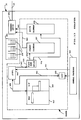
- the preferred embodiment of the shaper is described in FIG.13. It is implemented in the adapter 20 supporting the output lines 25 in the network node.
- a general processor 930 fills up a User Table (UT) 935 containing in each entry a traffic identifier and the number of entries to be reserved in the standby calendar for the said traffic. This operation is performed each time a traffic is added, changed or removed.
- the general processor 930 of the adapter which is not part of the shaper, sends to the a control device 940 of the shaper, via the link 937, the request for starting the update of the standby calendar as soon as the User Table is ready.
- the control device 940 sorts the data related to the traffics and updates thru link 939 two tables: one BandWidth (BW) table 947 with the traffic identifier in the descending order of the bandwidth share and pointing to the LinkTable (LT) 949, the second table, having all the traffic identifiers having the same bandwidth share.
- BW BandWidth
- LT LinkTable
- the control device 940 sends through link 943 to the placement device 950 described in FIG.10, the data to update the STANDBY CALENDAR 957 .
- These data are used by the placement device 950 which computes all the entries corresponding to one traffic.
- the data are sent to the STANDBY CALENDAR via link 955.
- the ACTIVE CALENDAR 959 sends in sequence the data to the transmit device 965 which is not part of the SHAPER, the traffic identifier being sent through link 965 to the TRANSMIT DEVICE 970.
- the cells for each traffic are stacked in queues 978.
- the transmit device knows how to fetch the cell corresponding to the traffic identifier which is in the storage 975 and sends it onto the output line 25.
- the priority traffics in other queues 978 are analyzed by the transmit device; if there is no cell to send an elapse timer is set or an idle cell is sent.
- the STANDBY CALENDAR 957 once filled up starts sending the entries via link 960.
- This second transfer of data is then taken as the only one by the TRANSMIT device 970: when the data are received thru link 960, link 965 is ignored and vice-versa.
- the STANDBY calendar has been swapped to become the ACTIVE CALENDAR.
- the placement device has detected the end of the first calendar 957 and in consequence, starts filling up the second calendar 959 sending data to it thru the link 956. The reverse operation happens when the calendar being filled up is ready.
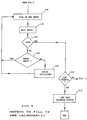
- the step 65 initializes a pointer to the first entry in the calendar.
- Step 67 is for reading the corresponding entry and request for a cell of the corresponding user (traffic) identifier for identifying the connection. If the entry is zero, checked by test 68, this means that no user traffic is actually scheduled in this entry of the calendar and the process goes on with step 71. If the result of test 68 is no, the test 69 is performed to check if one cell is ready to be sent in the waiting queue of the traffic. If yes, the cell is sent in step 71 over the output line.
- step 73 If no cell is ready to be sent, the test 73 is performed to check if a priority traffic has been notified to the system. If YES, the cell of said priority traffic is sent in step 71, if NO, no cell at all has to be sent, and the step 75 is performed. In step 75 two possible implementations for no cell sent: either an elapse timer is set corresponding to the cell departure time or an idle cell is sent: this specific cell will be destroyed by the receiving terminal. After cell departure time is over, if the result of test 77 is yes, which means that a calendar swap status is pending, then the swap between standby and active calendar is performed in step 81 and the process restarts as if the answer to test 77 was NO. The entry in the calendar is incremented in step 79 and the process goes on with step 67.
- Figure 5 and 6 illustrate the method for preparing the standby (or next active) calendar.
- a new standby calendar is prepared.
- the first step consists in calculating the number of cells to be placed in the calendar for the traffic. When the calculation is over, if the answer to test 110 is YES, the standby calendar is reset and a list of sorted user traffics is created in step 120.
- the sorting criterion is the traffic bandwidth share in the descending order.
- the first step to fill up the calendar is to find the first available slot in step 130; in step 140 the traffic having the greatest bandwidth share is identified and the first entry is filled up with the identifier of said user traffic in step 150.
- step 170 The next ideal entry for said traffic is considered in step 170. If, the end of calendar is reached, all the entries have been reserved for said user traffic, the answer to test 160 is YES then the test 210 is performed. If the user traffic is the last one in the list of traffic, the calendar is ready to be swapped and the status 'calendar ready to swap' is set in step 215. This means that the standby calendar is ready to be swapped to the active calendar. If the answer to test 210 is NO, there is another traffic for which the entries need to be reserved in the calendar and the process goes on with step 130. If the answer to test 160 is NO, this means that all the entries have not been reserved for the current traffic.
- step 150 the entry is filled up with said traffic identifier. If the answer to test 180 is no, the collision needs to be solved in step 200 with the method explained later in FIG.10. The process goes on with step 170 to achieve the placement of the entries for one traffic then for all the traffics and set the status 'calendar ready to swap'.
- the CDV for a given traffic used in the method of the invention is considered as depending not only on the deviation of the final departure placement of cells versus the ideal placement but also the bandwidth share required by the connection. It is assumed that for the same deviation of the entries reserved for two traffics, from their ideal position the CDV will be greater (and thus more sensible for the control of traffic congestion in the network) for the traffic using a larger bandwidth share than if the traffic requires a smaller bandwidth share. In consequence, the entries for the traffics having the highest bandwidth share are reserved first in the calendar. Then for each traffic, each entry is placed, following the ideal positions and when the positions are not empty, because it is already reserved for another traffic, the nearest free entry is taken.
- the worst case is found with a test case using 99.8% of the slots (or bandwidth) with many connections having a number of slots close to each other but not equal.
- the CDV distribution of the 600 connections calendar built with this test case is shown with the distribution diagram of FIG.8: 255 connections have a CDV centered on 20%.
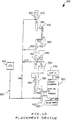
- FIG.10 represents the placement device 950: it is the implementation of the placement method of the entries of one given traffic in the standby calendar.
- the control device 940 sends a command of 'search placement for said traffic' thru a link 943 to a counter SEARCH 410.
- the counter SEARCH points to one address of the calendar 957 read in a register ADDRESS 400 thru a link 540, which is the current address to be searched.
- the entry read at this address of the calendar is sent thru a link 520 from the calendar 957 to a DECODE EMPTY device 420 which checks is the entry is empty. If it is empty, the user identifier read in a buffer 430 is sent to the calendar via link 530 is written in said pointed entry of the calendar.
- the current address read in the ADDRESS register 400 which is the address to be searched by the counter 410, has been sent thru a link 550 from an ADDER 460 where are added the following values: a fixed increment sent from a register INCR 440 sent via a link 570, a value in a analyser 450, which is zero or +1, sent via a link 560 and the preceeding value of the address stored in the ADDRESS register 400 and resent to the adder 460 via a link 580.
- the register 440 contains the increment value: it is the value of the ideal interval between two entries. This value is computed by the Control Device 940: it is the quotient of the division of the total number of entries in the standby calendar, 2**14 for our example, by the number of entries to be reserved in the calendar for said traffic.
- the control device sends thru link 943 the quotient, the remainder and the divisor of the division described above thru the link 943.
- the quotient is sent internally to the placement device, thru a link 640 and then a link 650 to the increment register 440 where it is stored.
- the remainder is sent internally to the placement device, thru link 640 then thru a link 660 where it is stored in a register REST 480.
- the divisor which is the number of entries to be reserved in the standby calendar for said traffic, is sent internally to the placement device, thru link 640 to be stored in the decrementer BW 470.
- the control device once these initializations done for one traffic, sends a command of 'search placement for said traffic' to the SEARCH counter 410.
- search operation each time an entry is written in the standby calendar for said traffic, the decrementer 470 is decremented of 1 via a link 680.
- An analyzer 450 combines the values of the decrementer 470 and the register 480 thru two links, respectively 590 and 600; then it decides to send zero or + one to the adder thru the link 560.
- the analyzer will send the value +1 as many times as the number stored in the register REST.
- the distribution of zero and +1 is regular between all the entries to be reserved in the calendar for one given user traffic.
- the anlyzer will send +1, one time on (N-r)/r: this implies that one entry upon (N-r)/r reserved for said traffic will be spaced from the next one by q + 1 the remaining ones being spaced from the next one by q.
- active and standby calendars of 2**14 entries are considered as sufficient to support OC3 speed lines.
- Each calendar entry is scanned at the cell departure beat over the output line which is close to 2.7 ⁇ seconds.
- the chief parameter that governs the number of entries of the calendar is the smallest share of the medium bandwidth that can be attributed to a single connection. For instance, a calendar for an OC3 which a a payload bandwidth of 149.760 Mbps may require 2 **14 entries since the smallest increment of payload given to one user is roughly 149.10**6 / 16.10**3 or 9 kbps which is low enough to accomodate a voice channel (compressed 64 kbps channel).
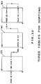
- Table 31 shows the ideal placement of the entries to be reserved for user traffics A, B, C and D, already ordered in the descending order of their bandwidth share.
- the traffic entries are placed in the ideal entries where the CDV is null. After this placement, 20% of the bandwidth share is unused and there are 6 cases of collisions (indicated with the symbol " ⁇ ") where connections are competing for the same departure time.
- the CDV value is increased to assign for the entry of connection C the next closest position around the ideal one which will be free.
- connection D illustrates the final placement of the connections entries in the calendar once the collisions have been solved.
- FIG.9 a sample of input and output data flows illustrating the shaping of the traffic with the solution of the invention.
- Connection 1 has nominally 40% of the bandwidth
- connection 2 has 20%
- connection 3 has 10%
- connection 4 has 5%.
- the table 320 illustrates a random input sampling and table 330 the shaped output sampling.
- Each column in the tables is the sampling of cells actually accumulated or sent over a standardized 10 cell period of the output line. The figure shows that the output traffic is much more regulated, due to the action of the shaper, than the input traffic: bursts and spaces between cells are improved.
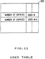
- the interface with the device in charge of the adapter and the shaper is the User Table (UT) as illustrated in FIG.11.
- This table has as many entries as the number of traffics to manage. Whenever the general processor of the adapter wants to update the calendar, it has just to update the User Table at the entry corresponding to the traffic. Each entry contains the traffic identifier and the number of entries that must be reserved for said traffic in the next calendar.
- the shaper is activated to perform a rebuilding of the standby calendar that will replace the active calendar.
- the tables described in FIG.12 and used in the preferred embodiment shows how the user traffics which have a larger sharing of the medium bandwidth have their entries placed first in the calendar.
- the sorting of the connections is based on the number of necessary entries: the traffics with a higher bandwidth share have a greater number of entries reserved in the calendar.
- two extra tables are added to the user's table 935 and prepared by the control device 940 (in FIG.13) before the updating of the standby calendar may start.
- the first one is the bandwidth table (BW table) 947 which has 2**14 entries; at each re-computation of the calendar this table is first cleared, then the User's Table is scanned.
- the high speed adapters will need in the shaper a set of two calendars per output line.
- the same hardware implementation as described above is used and the set of two calendars repeated as many times as the number of output lines.
- the size of the calendar is always related to the bandwidth of the line: as said before, for a line speed of 150 Mbps a 16K (2**14) entries calendar is used ; for a line of 45 Mbps a 8K entries calendar provides also a satisfactory level of granularity.
- the size of the calendar can be settable by program or command.
Abstract
A method and an apparatus for shaping the output traffic in the transmit part of an network node adapter equipped with output lines. The network node supports fixed length cell switching user information traffics between a source unit and a destination unit; the invention uses two lookup tables called the active and the standby calendars (959,957) per one of said output line, each entry in the calendars representing the position of one cell in the output cell stream which will be sent onto said output lines; In the preferred embodiment three parameters tables (935,947,949) are used to store the information on the user traffics in the descending order of their bandwidth share negotiated at traffic establishment time; controlled by the control device (940), the placement device (950) places the entries in the standby calendar reserved for each traffic; once filled up the standby calendar is swapped to the active calendar; the active calendar is continuously read and the corresponding cells are sent onto the output line by the transmit device (970).
Description
- This invention deals with problems of traffic control in the fixed length cells switching high speed networks and more particularly with a shaping method and apparatus to be implemented in an ATM network node adapter.
- The basic advantage of the new high bandwidth, low delay, fixed length cell based transfer mode techniques, such as Asynchronous Transfer Mode (ATM),is to allow multiplexing and switching of different types of information over the same network: data, voice, image, video, while optimizing the bandwidth and resources utilization.
- Congestion control inside these networks is one of the major problems to be resolved. As the cells are short, no space is allocated in the header to enable error recovery for the cell payload. If one cell of the block has been lost or discarded by the network in case of network congestion, error recovery is performed at the higher-level by recovery protocols retransmitting the user data block. The error rate being extremely low in the internode links, cells lost because of random errors is not a potential problem. However, when a node discards cells for reason of traffic congestion detected, it is unlikely that these cells will come from a small number of logical data blocks. Discarding 1000 cells, if the average user data blocks length is 2KBytes(a low estimate), sent as 43 cells, may cause the network to absorb a retransmission of 43,000 cells! This case indeed is the worse case when the 1000 messages come from 1000 different connections. That is why the protocols need to be efficient enough to limit the congestion problems in this type of networks.
- In the ATM connection-oriented networks, the end-to-end traffic of data for one user, between the source and the destination, is represented by a Virtual Connection (VC); several Virtual Connections may be grouped in a Virtual Path (VP) that can be switched as a unit. The bandwidth is allocated dynamically as part of a connection setup signalling procedure that precedes end-to-end information exchange. At call admission time, the source user provides, in addition to the destination point, a set of parameters, called the traffic descriptors, which attempts to describe the traffic that will be generated onto the links. For instance, a mandatory descriptor is the peak cell rate of the connection, R. If this parameter is sufficient to fully describe Constant Bit Rate (CBR) connections, i.e., periodic stream of cells such as uncompressed voice, further parameters are necessary to describe Variable Bit Rate (VBR) connections such as those for video traffic. The burst of traffic is measured by the average cell rate and the average duration of an emission at the peak rate R in most of the high speed networks literature. As seen above, in ATM networks, cells may be lost or unacceptable delays can be induced in case of traffic congestion. Depending on the type of traffic conveyed over the ATM network, the first or the second just mentioned behavior of the network, in case of congestion, may damage the quality of traffic over the virtual connections: for voice traffic, cells can be lost but a delay in transmission is unacceptable. When data is transferred on the virtual connection, the delay can be acceptable but not the cell loss. That's why the network guarantees a Quality of Service (QoS). The QoS guaranteed by a network is, in most cases, expressed in terms of cell loss probability and maximum end-to-end delay for a cell, independently of network topologies and protocols. One can note that the end-to-end delay between two users is increased if the end-to-end connection crosses different network entities (private or public carrier networks) which have their own protocols and traffic management.
- In order to meet the QoS, the network nodes have to control the traffic congestion both at connection admission time and once the connections established.
- At connection admission time the access node has to decide if it can accept the connection or not: its decision is based on the actual load of the links, and its analyzing of the traffic parameters of the connection. Moreover, it has also to compute a path table to carry this overload of traffic through the different nodes. If no path is found, the call is rejected. It is important to note that the decision to accept a new call has to be taken not only if the network node estimates that the QoS for the connection will be met but also if it is sure that the added traffic will not have a significant impact on the QoS of all the connections already established.
- A first control on traffic congestion, once the connection is established, is performed by the policing function implemented in a device, the policer, of the network access node adapter. The policer will detect and penalize the violation of the peak cell rate on the current traffic compared to the one required at call set up. Instead of the peak cell rate, another descriptor such as the Sustainable Cell Rate, the SCR (that is not yet a standardized parameter) can be used as a criterion for the policing function; in the following of the description, any reference to the peak cell rate can be replaced by SCR. The policing function is also referred in the ATM literature as the Network Parameter Control (NPC) or the Usage Parameter Control (UPC) depending if the source unit is a Network Node or a Customer Premise Node; Indeed, an efficient policing function should be transparent as long as the traffic characteristics provided by the source at call setup are met. When the number of cells received exceeds the number of cells corresponding to the peak rate negotiated at traffic establishment time, the policing function will discard or tag the user cells depending on the cell loss priority.
- A second control of traffic congestion consists in shaping the output network node traffic by spacing the cells departures in such a way that the time between two departures of cells for a same connection is never below the minimal value negotiated at connection setup time. It has been shown that, on the average, the multiplexing of spaced cells tends to decrease the 'burstiness' of the aggregate traffic and then allows a better utilization of the network resources.
- FIG.1 shows the shaping principle applied to the
input cells stream 1. The shaded cells have been sent by a first user and the cells marked with a cross have been sent by a second user. The result of shaping is shown with the output cells stream 2: the cells marked with = have been moved and the departure time between two cells have become more regular. The spacing of the cells is done in respect with the bandwidth share required by the users: in the output cells stream, the departure time between two cells is smaller for the cells of the first user than for the second user because the first user has required a greater bandwidth share than the second user; moreover, in the output stream the bursts of traffic have decreased: one can note that the groups of three cells of theinput stream 1 have disappeared in theoutput stream 2. - The policing function is implemented in the access network nodes. The device implementing the policing function, the policer, is part of the high speed adapter cards; it controls and, if necessary, penalizes the traffic entering the network.
The shaping function is implemented in the devices accessing a network: they can be Customer Premise Nodes accessing an ATM network or a Network Node at the boundary of a first ATM network and intending to access another ATM network. The device implementing the shaping function, the shaper, is also part of the high speed adapter cards and controls the sending of the output traffic cells. FIG.2 shows a shaper and a policer implemented in a network node. 15 are the input lines conveying the input cells streams which are received by theinput adapters 10; in eachinput adapter 10 the policer controls and penalizes, if necessary, the cells stream for each user; than the cells are switched in theswitch 30 and sent to theoutput adapters 20. In eachoutput adapter 20 there is a shaper which spaces the cells which are sent to theoutput lines 25. FIG.3 shows a network topology to convey the traffic of users from thesource unit 40 to thedestination unit 60 through the twonetworks nodes 45 are the access nodes; the policers are implemented in theseaccess nodes 45. The shapers are implemented in thesource unit 40 and in thenode 50 which is at the boundary of thefirst network 42 and which accesses thesecond network 52. As thedestination unit 60 may be a Customer Premise Node having implemented a policer, it is recommended to implement also a shaper in thenode 55 located at the boundary of thenetwork 52. - Many policing schemes have recently been studied; some of the most known are the leaky bucket, the jumping window, the moving window as described by Raif O. Onvural in his book entitled "Asynchronous Transfer Mode Networks: performance issues", Artech House edition. Without lack of generality, each policing function estimates one or more traffic parameters for a given period of time P. As this period of time P decreases, the policer may become non-transparent to users generating a traffic in conformance with the parameters negotiated at connection establishment time. On the other hand, as P increases, the policer takes longer to detect that the source exceeds its declared characteristics. However, the latter approach is more fair since it allows the user to generate a stream of cells that have short-term fluctuations. This is done at the expense of more memory requirements at the node level.
- The only policing function proposed as a standard by the ITU (International Telecommunications Union), is the Generic Cell Rate Algorithm (GCRA). Details of the GCRA are given in the ATM Forum, "ATM User-Network Interface Specification", Version 3.0, 1994. Its role is, for each connection, to monitor the traffic arriving upstream according to the cell period T (T corresponds to the inverse of the peak cell rate R) and a given tolerance τ on this period. Basically, a cell is assumed to be conforming if the time elapsed between the arrival of two consecutive cells (belonging to the same connection) is greater than or equal to T - τ. If not, the cell is assumed to be non-conforming and is tagged and possibly discarded.
- The policer discards cells not only because the source of traffic has violated the parameters negotiated at connection establishment but also because of a distorsion in the cell stream well known as jitter or Cell Delay Variation (CDV). This distorsion is due to the queuing of the cells at each intermediate network node and more generally the multiplexing of the cells on the output lines. The magnitude of the jitter depends on many parameters: the connection peak rate, the peak rate of the other connections that share the same link, the link load, the number of nodes passed through etc...A consequence of the jitter is to induce, as the user cells travel through the network, some distortion on the traffic parameters declared by the source upstream. Especially, the instantaneous peak cell rate R' which may be modified and may pass beyond the value R declared by the source upstream at connection establishment time. In the worst case R'>R and the policing function with a short measurement interval (small period of time P) may take undesirable discarding actions. This is typically the case of the GCRA when the specified tolerance τ, named Cell Delay Variation Tolerance (CDVT), is small. That's why the shaping function will buffer cells so that the departure rate from a node is less that the arrival rate. It has been shown that the multiplexing of spaced cells tends to decrease the "burstiness" of the aggregate traffic and then allows a better utilization of the network resources.
- Policing and shaping control techniques should take into account the real-time constraints; as implemented in high speed network node adapters dealing with lines at several hundreds of Megabits per second. For example, the cell transmission time (cell time cycle) is about 2.7µs for a line speed of 155.52 Mbps (OC-3), and less than 0.7 µs for a line speed of 622.08 Mbps (OC-12). This implies that the shaping and policing methods have a very short computing time not to pass the cell cycle. For instance, assuming that only ten instructions are needed to both compute a cell transmission time and queue the cell to an output buffer; assuming that each instruction takes no more than one time cycle, the execution requires from the processor more than 14 Mips (Million of instructions per second) devoted to this task, for an OC-12 output link. Usually hardware devices are needed and only simple computations (a few software instructions) and basic manipulations of cells are possible. As a consequence, shaping function will have to cope with a trade-off between complexity and performance.
- Taking into account these above performance considerations, two shaping schemes are briefly examined hereunder. They represent the state of the art.
- The first one, relies on a very basic principle: the shaping function sends a given number, p, of cells at the link speed C, and keeps "silent" (i.e. the cells are buffered) till p(C/R-1). If this approach requires no computation nor complex operations at the cell level, the CDV induced is quite bad and the tolerance that should be accommodated at the GRCA level to accept all the cells would be typically p(C/R-1). Some chips are available and described in "SARA Chipset Technical Manual" Transwitch, November 1992, "FRED Chipset ATM Overview" National Semiconductor, 1993, "Adaptation Layer Controller (ALC)" Fujitsu, October, 1993, "User's Manual µPD98401 Local ATM SAR CHIP (Preliminary)", NEC, June 1994 and "ATMIZER MegaCore" Preliminary specifications 1993 by LSI Logic Corporation Milpitas CA describing a device having a "Pacing Rate Unit" . These chips are rather used for terminals ATM connection than for ATM nodes, are using one or two cascaded leaky buckets to shape the output traffic. These solutions are not satisfactory for the ATM node because they do not suppress but only spread the bursts of traffic.
- The second one, more sophisticated, is detailed in Eugen Wallmeier and Tom Worster article entitled "The spacing Policer, an algorithm for efficient peak bit rate control in ATM networks", published in the Proceedings of the of the XIV International Switching Symposium, Yokohama, Japan, October 25-30, 1992. For an incoming cell of one connection, the time between two cell transmissions is such that the output peak rate is met, and the cell is queued to a list-of-cells that have to be sent at the same time tk. This list is referenced by the nth entry of a cyclic calendar with N inputs. A new entry of the calendar is seek at each cell time cycle, and the list-of-cells that have to be sent at time tn (0≦n<N) if any, is moved and queued to an output list. In short, the following operations are done at each cell time cycle:
- Computing the transmission time ti for the incoming cell belonging to connection i
- Enqueueing the cell to the list-of-cells at the nth (0≦n<N). entry of the calendar.
- Moving the list-of-cells of the current position m (0≦m<N) of the calendar to the output list.
- Sending the first cell to the output list.
- Incrementing the calendar position.
- The state of the art described above and all known existing shaping schemes rely on the same principle: they compute a cell transmission time at each cell arrival, which depends on both current time and the time when the last cell was transmitted. For this reason, these shaping schemes may be referred as cell-basis schemes.
- The object of this present invention is to provide in the network node adapters transporting fixed length cells, a shaping method which controls and minimizes the CDV with a minimum of computing resources. This would limit the bursts of traffic and thus the problem of traffic congestion in these high speed networks. This invention would also allow to anticipate the real traffic and thus avoid any penalization of the policers when accessing another network.
- In a fixed length cell switching network, the shaping method of the invention implemented in the adapter supporting output lines, consists in scheduling in advance the departure time of the cells for each transfer of traffic between a source unit and a destination unit.
- The shaping function is activated each time a change has occured in the traffic supported (new traffic added, end of traffic, modification in the traffic already established). This anticipated computing reduces significantly the number of operations performed in the cell cycle to send a cell onto an output line.
- The method provides two lookup tables called the active and the standby calendars per one output line of the adapter, each entry in the calendars storing a traffic identifier representing the position of one cell in the output cell stream which will be read by the transmit device and sent onto the output line;
At each change with the traffics supported, the standby calendar is filled up with the new output stream and once the standby calendar is filled up it becomes the active one; the active calendar is continuously read and the transmit device is activated at each entry read to send onto the output line the cell corresponding to the traffic identifier read. - The invention implies the usage of a first lookup table, the active calendar, which is read by the device in charge of sending the output sequence of cells over the output line At each change with the traffics established in the node, a second lookup table, the standby calendar, is filled up with a new arrangement of the sequence of cells of all traffics established. Once the arrangement achieved, the active calendar is swapped to the standby one.
- In a feature of the invention, the fixed length cell switching network node is an ATM network node supporting user connections: Virtual Connections and Virtual Path connections between the source unit and the destination unit.
- With the hardware implementation of the invention as described in the preferred embodiment section having a calendar of 2**14 entries, the performance expected allow the support of OC3 lines and up to 100 swapping operations of the calendar per second. This former result would allows up to 100 modifications per second in the set of connections particularly necessary to support for the ATM switched networks. A speed line up to OC12 can be supported with the corresponding size of the Random Access Memory units of the hardware implementation described below.
-
- FIG.1 illustrates the shaping principle.
- FIG.2 shows the policer and shaper in the ATM network node adapters.
- FIG.3 shows the shaper and the policer placed at the boundary of ATM networks.
- FIG.4 is the algorithm describing the process of reading the active calendar and sending the cells over the propagation medium.
- FIG.5 is the first part of the algorithm describing the building of the standby calendar. In this part the connections are sorted in the descending order of their bandwidth share.
- FIG.6 is the second part of the algorithm describing the building of the calendar. It describes the placement of the entries corresponding to each connection.
- FIG.7 illustrates the calendar building with four connections.
- FIG.8 is the distribution diagram of the CDV values obtained by the placement simulated for 600 connections.
- FIG.9 illustrates the spacing of output traffic with the shaping method of the invention.
- FIG.10 is the hardware implementation of the building of the calendar.
- FIG.11 represents the User's Table.
- FIG.12 illustrates the chaining of the User's Table, bandwidth table and link table used for the sorting hardware mechanism.
- FIG.13 shows the apparatus implementing the shaping function.
- As shown in figures 2 and 3 described later in this section, the shaping function of the invention is implemented in the output adapter or the transmit part of the adapter of a fixed length cell switching network node supporting output lines. The node supports transfers of information for a given user between a source unit and a destination unit. These transfers of information will be referred as user traffics or traffics in the following.
- The method of the invention consists in preparing in advance the departure of the cells for all the traffic established in the network node and which will be sent onto the output lines. For each output line, the cell stream is stored in two lookup tables called the calendars: the active calendar and the standby calendar. In said calendars, one entry corresponds to a time unit required for cell departure; each entry of the calendars is reserved for the departure of one cell of a given user traffic if it is filled up with the identifier of the user traffic. The the active calendar is continuously read; for each entry read, a cell of the corresponding traffic is sent onto the output line. If the entry is empty, an elapsed time corresponding to the cell departure time is sustained by the transmit device or an idle cell is sent onto the output line and will be discarded by the remote device. When the last entry of the calendar is read, the reading restarts at the first entry. At each change with the user traffics (new traffic added, one traffic terminated or one traffic modified), the second calendar, the standby calendar, is prepared. The entries in the standby calendar are reserved for the traffics established in such a way that the Cell Delay Variation (CDV) is minimal. The CDV is induced by the variation between the final placement of the entries compared to the ideal one. The ideal placement of the entries for one user traffic corresponds to the entries equally spaced with a number of entry corresponding to the bandwidth share required by said traffic. If one entry of the ideal placement is already reserved for another traffic, there is a collision: the entry finally reserved will be the one inducing a minimum CDV on the placement; the method of placement to solve the collision with a minimum CDV is explained later with FIG.10. Once ready, the standby calendar is swapped to the active calendar.
- The preferred embodiment of the shaper is described in FIG.13. It is implemented in the
adapter 20 supporting theoutput lines 25 in the network node. Ageneral processor 930 fills up a User Table (UT) 935 containing in each entry a traffic identifier and the number of entries to be reserved in the standby calendar for the said traffic. This operation is performed each time a traffic is added, changed or removed. Thegeneral processor 930 of the adapter which is not part of the shaper, sends to the acontrol device 940 of the shaper, via thelink 937, the request for starting the update of the standby calendar as soon as the User Table is ready. Then, thecontrol device 940 sorts the data related to the traffics and updates thrulink 939 two tables: one BandWidth (BW) table 947 with the traffic identifier in the descending order of the bandwidth share and pointing to the LinkTable (LT) 949, the second table, having all the traffic identifiers having the same bandwidth share. Thecontrol device 940 sends throughlink 943 to theplacement device 950 described in FIG.10, the data to update theSTANDBY CALENDAR 957 . These data are used by theplacement device 950 which computes all the entries corresponding to one traffic. The data are sent to the STANDBY CALENDAR vialink 955. In parallel, theACTIVE CALENDAR 959 sends in sequence the data to the transmitdevice 965 which is not part of the SHAPER, the traffic identifier being sent throughlink 965 to the TRANSMITDEVICE 970. In thestorage 975, the cells for each traffic are stacked inqueues 978. The transmit device knows how to fetch the cell corresponding to the traffic identifier which is in thestorage 975 and sends it onto theoutput line 25. When the entry of the calendar is zero the priority traffics inother queues 978 are analyzed by the transmit device; if there is no cell to send an elapse timer is set or an idle cell is sent. TheSTANDBY CALENDAR 957 once filled up starts sending the entries vialink 960. This second transfer of data is then taken as the only one by the TRANSMIT device 970: when the data are received thrulink 960, link 965 is ignored and vice-versa. The STANDBY calendar has been swapped to become the ACTIVE CALENDAR. In parallel, at the same time, the placement device has detected the end of thefirst calendar 957 and in consequence, starts filling up thesecond calendar 959 sending data to it thru thelink 956. The reverse operation happens when the calendar being filled up is ready. - The method implemented in the
calendars step 65 initializes a pointer to the first entry in the calendar.Step 67 is for reading the corresponding entry and request for a cell of the corresponding user (traffic) identifier for identifying the connection. If the entry is zero, checked bytest 68, this means that no user traffic is actually scheduled in this entry of the calendar and the process goes on withstep 71. If the result oftest 68 is no, thetest 69 is performed to check if one cell is ready to be sent in the waiting queue of the traffic. If yes, the cell is sent instep 71 over the output line. If no cell is ready to be sent, thetest 73 is performed to check if a priority traffic has been notified to the system. If YES, the cell of said priority traffic is sent instep 71, if NO, no cell at all has to be sent, and thestep 75 is performed. Instep 75 two possible implementations for no cell sent: either an elapse timer is set corresponding to the cell departure time or an idle cell is sent: this specific cell will be destroyed by the receiving terminal. After cell departure time is over, if the result oftest 77 is yes, which means that a calendar swap status is pending, then the swap between standby and active calendar is performed instep 81 and the process restarts as if the answer to test 77 was NO. The entry in the calendar is incremented instep 79 and the process goes on withstep 67. - Figure 5 and 6 illustrate the method for preparing the standby (or next active) calendar. Upon request of
general processor 930 in FIG.13 which has just updated the User Table, a new standby calendar is prepared. The first step consists in calculating the number of cells to be placed in the calendar for the traffic. When the calculation is over, if the answer to test 110 is YES, the standby calendar is reset and a list of sorted user traffics is created in step 120. The sorting criterion is the traffic bandwidth share in the descending order. The first step to fill up the calendar is to find the first available slot in step 130; in step 140 the traffic having the greatest bandwidth share is identified and the first entry is filled up with the identifier of said user traffic instep 150. The next ideal entry for said traffic is considered instep 170. If, the end of calendar is reached, all the entries have been reserved for said user traffic, the answer to test 160 is YES then thetest 210 is performed. If the user traffic is the last one in the list of traffic, the calendar is ready to be swapped and the status 'calendar ready to swap' is set instep 215. This means that the standby calendar is ready to be swapped to the active calendar. If the answer to test 210 is NO, there is another traffic for which the entries need to be reserved in the calendar and the process goes on with step 130. If the answer to test 160 is NO, this means that all the entries have not been reserved for the current traffic. If the answer to test 180 is YES, this means that the entry is empty and the process goes on withstep 150, the entry is filled up with said traffic identifier. If the answer to test 180 is no, the collision needs to be solved instep 200 with the method explained later in FIG.10. The process goes on withstep 170 to achieve the placement of the entries for one traffic then for all the traffics and set the status 'calendar ready to swap'. - The CDV for a given traffic used in the method of the invention is considered as depending not only on the deviation of the final departure placement of cells versus the ideal placement but also the bandwidth share required by the connection. It is assumed that for the same deviation of the entries reserved for two traffics, from their ideal position the CDV will be greater (and thus more sensible for the control of traffic congestion in the network) for the traffic using a larger bandwidth share than if the traffic requires a smaller bandwidth share. In consequence, the entries for the traffics having the highest bandwidth share are reserved first in the calendar. Then for each traffic, each entry is placed, following the ideal positions and when the positions are not empty, because it is already reserved for another traffic, the nearest free entry is taken. Many calendar building operations using the above method of placement, based on various test cases varying the number of traffics and their placement of entries in a large range, have been tried. These simulations have highlighted that a right-left search around the ideal position gives always a better result than right-only search. Assuming I is the ideal interval between two entries reserved for one traffic in a calendar by the placement device, corresponding to the bandwidth share negotiated at traffic establishment time and i, the minimal interval between two entries reserved for one traffic in a calendar by the placement device, the CDV for said traffic is expressed by (I-i)/I (expression 1). According to
expression 1, the results of tests performed applying the method of the invention provides a distribution of the CDV value centered around 10%. The worst case is found with a test case using 99.8% of the slots (or bandwidth) with many connections having a number of slots close to each other but not equal. The CDV distribution of the 600 connections calendar built with this test case is shown with the distribution diagram of FIG.8: 255 connections have a CDV centered on 20%. - FIG.10 represents the placement device 950: it is the implementation of the placement method of the entries of one given traffic in the standby calendar. At one point in time the
control device 940 sends a command of 'search placement for said traffic' thru alink 943 to acounter SEARCH 410. The counter SEARCH points to one address of thecalendar 957 read in aregister ADDRESS 400 thru alink 540, which is the current address to be searched. The entry read at this address of the calendar is sent thru alink 520 from thecalendar 957 to a DECODEEMPTY device 420 which checks is the entry is empty. If it is empty, the user identifier read in abuffer 430 is sent to the calendar vialink 530 is written in said pointed entry of the calendar. If the pointed entry of said calendar is not empty, there is a collision and the entries +1, -2, +3, -4 etc... are successively decoded until an empty entry is found. When found, the user identifier value is written as above. The current address read in theADDRESS register 400, which is the address to be searched by thecounter 410, has been sent thru alink 550 from anADDER 460 where are added the following values: a fixed increment sent from aregister INCR 440 sent via a link 570, a value in aanalyser 450, which is zero or +1, sent via alink 560 and the preceeding value of the address stored in theADDRESS register 400 and resent to theadder 460 via alink 580. Theregister 440 contains the increment value: it is the value of the ideal interval between two entries. This value is computed by the Control Device 940: it is the quotient of the division of the total number of entries in the standby calendar, 2**14 for our example, by the number of entries to be reserved in the calendar for said traffic. When starting the placement of said traffic, the control device sends thrulink 943 the quotient, the remainder and the divisor of the division described above thru thelink 943. The quotient is sent internally to the placement device, thru alink 640 and then alink 650 to theincrement register 440 where it is stored. The remainder is sent internally to the placement device, thrulink 640 then thru a link 660 where it is stored in aregister REST 480. The divisor, which is the number of entries to be reserved in the standby calendar for said traffic, is sent internally to the placement device, thrulink 640 to be stored in thedecrementer BW 470. The control device, once these initializations done for one traffic, sends a command of 'search placement for said traffic' to theSEARCH counter 410. When search operation is performed, each time an entry is written in the standby calendar for said traffic, thedecrementer 470 is decremented of 1 via alink 680. Ananalyzer 450 combines the values of thedecrementer 470 and theregister 480 thru two links, respectively 590 and 600; then it decides to send zero or + one to the adder thru thelink 560. The analyzer will send the value +1 as many times as the number stored in the register REST. The distribution of zero and +1 is regular between all the entries to be reserved in the calendar for one given user traffic. Considering that for N entries to reserve for a given user traffic, if the remainder in the register REST is r, the quotient being q in the register INCR in the division of the total number of available entries in the calendar by the number of entries N for said traffic, then the anlyzer will send +1, one time on (N-r)/r: this implies that one entry upon (N-r)/r reserved for said traffic will be spaced from the next one by q + 1 the remaining ones being spaced from the next one by q. In the case where (N-r)/r is not an integer, the integer immediately less than this number is taken. For a given traffic, the process of placement of entries in the calendar stops when the number of entries to be placed in the calendar stored in thedecrementer 470 is zero. - In the preferred embodiment, active and standby calendars of 2**14 entries are considered as sufficient to support OC3 speed lines. Each calendar entry is scanned at the cell departure beat over the output line which is close to 2.7 µseconds. The chief parameter that governs the number of entries of the calendar is the smallest share of the medium bandwidth that can be attributed to a single connection. For instance, a calendar for an OC3 which a a payload bandwidth of 149.760 Mbps may require 2 **14 entries since the smallest increment of payload given to one user is roughly 149.10**6 / 16.10**3 or 9 kbps which is low enough to accomodate a voice channel (compressed 64 kbps channel). Another parameter that may have to be considered is the granularity in the adjustment of the bandwidth the network manager may want to control. If there is no special restriction imposed on the sharing of the bandwidth (other than what has just been said on the granularity and on the minimum increment), there is no perfect solution (CDV = 0) because a situation may always be found where at least two users are competing for the same departure time of a cell.
- The result of the method of the invention for the placement of the entries of one user traffic minimizing the CDV is illustrated in FIG.7. Table 31 shows the ideal placement of the entries to be reserved for user traffics A, B, C and D, already ordered in the descending order of their bandwidth share. The traffic entries are placed in the ideal entries where the CDV is null. After this placement, 20% of the bandwidth share is unused and there are 6 cases of collisions (indicated with the symbol "∓") where connections are competing for the same departure time. The CDV value is increased to assign for the entry of connection C the next closest position around the ideal one which will be free. The same process is applied to connection D. Table 300 illustrates the final placement of the connections entries in the calendar once the collisions have been solved.
- Compared to the chip cited as prior art, the solution brings a significant advantage in suppressing the 'burstiness' of the output traffic. In FIG.9 is provided a sample of input and output data flows illustrating the shaping of the traffic with the solution of the invention. With this sample, 4 connections share 75% of the bandwidth.
Connection 1 has nominally 40% of the bandwidth,connection 2 has 20%, connection 3 has 10% andconnection 4 has 5%. The table 320 illustrates a random input sampling and table 330 the shaped output sampling. Each column in the tables is the sampling of cells actually accumulated or sent over a standardized 10 cell period of the output line. The figure shows that the output traffic is much more regulated, due to the action of the shaper, than the input traffic: bursts and spaces between cells are improved. - The interface with the device in charge of the adapter and the shaper is the User Table (UT) as illustrated in FIG.11. This table has as many entries as the number of traffics to manage. Whenever the general processor of the adapter wants to update the calendar, it has just to update the User Table at the entry corresponding to the traffic. Each entry contains the traffic identifier and the number of entries that must be reserved for said traffic in the next calendar. Once the user table is updated, the shaper is activated to perform a rebuilding of the standby calendar that will replace the active calendar.
- The tables described in FIG.12 and used in the preferred embodiment shows how the user traffics which have a larger sharing of the medium bandwidth have their entries placed first in the calendar. Thus, the sorting of the connections is based on the number of necessary entries: the traffics with a higher bandwidth share have a greater number of entries reserved in the calendar. To achieve it, two extra tables are added to the user's table 935 and prepared by the control device 940 (in FIG.13) before the updating of the standby calendar may start. The first one is the bandwidth table (BW table) 947 which has 2**14 entries; at each re-computation of the calendar this table is first cleared, then the User's Table is scanned. At each UT entry where a non zero bandwidth value is found, an entry is done in the BW table with the user identifier corresponding to the traffic having this bandwidth. Obviously, there may be many connections having the same bandwidth value share thus competing for the same entry in the bandwidth table. This is solved with a third table, the link table (LT table) 949, which links the traffics at the same bandwidth. Because the user traffic identifier are unique, no other conflict may occur in the LT table which has 2**13 entries like the UT. The building of the calendar starts with the generation of the BW and LT tables which are then read by the control device of the
shaper 940 to place all the traffics starting with the one having the highest bandwidth share to comply with the method of the invention. - The high speed adapters will need in the shaper a set of two calendars per output line. The same hardware implementation as described above is used and the set of two calendars repeated as many times as the number of output lines. The size of the calendar is always related to the bandwidth of the line: as said before, for a line speed of 150 Mbps a 16K (2**14) entries calendar is used ; for a line of 45 Mbps a 8K entries calendar provides also a satisfactory level of granularity. In a more sophisticated implementation of the invention, the size of the calendar can be settable by program or command.
Claims (12)
- A method for shaping the output traffic in the transmit part of an network node adapter equipped with output lines; said network node supporting fixed length cell switching user information traffics between a source unit and a destination unit; said source unit sending at user traffic establishment time a bandwidth share required; said adapter being equipped with a transmit device which reads the cells in a storage and sends them onto said output lines; said method being characterized in that it provides two lookup tables called the active and the standby calendars per one of said output line, each entry in the calendars representing the position of one cell in the output cell stream which will be sent onto said output lines; said method characterized also by the following steps:A) at each change with the user traffics supported, filling up the standby calendar with the new output stream and once said standby calendar is filled up, swapping the standby calendar to the active one;B) continuously reading the active calendar and activate the transmit device to send onto the output line the cell corresponding to the user traffic read;
- The method of claim 1 where the step B) includes the following steps:- reading one entry of the active calendar and sending the user traffic identifier read to the transmitting device;- detecting if the standby calendar is ready to swap and if it is the case, going on reading the same entry in the standby calendar; if no status of standby calendar ready to swap is detected going on with the same calendar; when reaching the end of calendar, restarting at the first entry.
- The method of claims 1 or 2 where the step A includes the following steps:- choosing the user traffic in the decreasing order of their bandwidth share;- reserving for each user traffic the entries corresponding to the smallest variation versus the optimal placement corresponding to said bandwidth share;- once the last user traffic reservation is performed in the standby calendar, setting the status for standby calendar ready to swap.
- The method of claims 3 where the reservation of the entries in the standby calendar includes the following steps:- ordering the user traffics in the decreasing order of their bandwidth share;- for each user traffic, reserving the entries corresponding to the bandwidth share requested at user traffic establishment time;- in case of collision finding the nearest right-left searched free entry.
- The method of claim 3 and 4 characterized in that the sorting of the user traffics in the decreasing order of their bandwidth share includes the following steps:- at each change with the user traffics preparing a table called the User Table (935) containing for each user traffic the user traffic identifier and the number of entries to be reserved for the user traffic;- preparing also two other tables containing the user traffics identifiers, the first one (947) with a list of different user traffics sorted in the decreasing order of their bandwidth share and a pointer to the second table (949); said second table containing for each entry pointed by said first table the list of user traffics having the same bandwidth share.
- The method of anyone of claim 1 to 5 characterized in that the fixed length switching network is an ATM network and the user traffics are Virtual Connections or Virtual Path Connections.
- The method of anyone of claim 4 to 6 characterized in that for placing the entries as required by the bandwidth share required at user traffic establishment time and before solving the possible collisions, the following steps are performed:- dividing the total number of entries available in the standby calendar by the number of entries to be reserved for one user traffic; r being the remainder and q the quotient of said division;- if r is equal to zero, reserving all the entries for said user traffic spaced with q entries in the calendar from the following entry;- if r is different from zero, reserving r entries spaced with q + 1 entries in the calendar from the following entry for said user traffic; the remaining entries to be reserved for said traffic being spaced with q entries in the calendar from the following entry for said user traffic;- regularly distributing entries spaced with q and q + 1 entries from the next entry for said traffic.
- The method of claim 1 to 7 characterized in that, if the entry read is unoccupied in task A) of claim 1, a timer is set with an elapsed time corresponding to the cell departure time.
- The method of claim 1 to 7 characterized in that, if the entry read is unoccupied in task A) of claim 1, an idle cell is sent over the output line.
- The method of claim 1 to 9 where the size of the calendar is settable by program or command.
- An apparatus implementing a shaping function in a fixed length cell switching network node adapter supporting output lines (25); said adapter comprising a transmit device able to send cells onto output lines for a given user traffic; said apparatus comprising:- first means (957) for storing a user traffic identifier in each entry and, once filled up, for sending data onto a link (960) to said transmit device;- second means (959) for storing a user traffic identifier in each entry and, once filled up, for sending data onto a link (965) to said external transmit device;- third means (947,949,935) for storing for each user traffic in the descending order of their bandwidth share, the user traffic identifier and the number of entries to be reserved for it in the first means (957);- control means to read in third means when a request is received from an external processor (930);- means (950) for sending the user traffic identifier for each user traffic the entries being the ones to be reserved in said first and second means for user traffic cells departure in an optimized order; data being sent to first means (957) if second means (959) is sending data onto the link (965) towards said transmit device; or data being sent via a link (956) to second means (959) if first means (957) is sending data towards said transmit device.
- The apparatus of claim 11 characterized in that the means (950) for sending the user traffic identifiers includes the following means:- fourth means for storing (400) an address;- means for checking (420) if an entry of a storage is empty or filled-up;- fifth means (430) for storing and sending thru a link (530) a user identifier;- sixth means (410) for reading in the first (957) or second means (959) an entry at the address read in the fourth means for storing (400); activating the means for checking (420) if the entry is empty, reading the fifth means for storing (430) and filling up the entry; receiving the command to starts the first reading operation for one given user traffic from the means (940) thru the link (943);- means for adding (460) the content of three storage means (440, 450,400) whose data is sent via links (570,560,580) and sending back the new address to the storage means (400);- seventh means for storing (440) a number sent from means (940);- eigth means for storing a number (480) sent from means (940);- ninth means for storing a number (470) sent from means (940); decrementing via link (680) of 1 the number stored, each time one entry is filled up by sixth means (410);- means for reading the storing eigth and ninth means (470,480), combining the values read and regularly sending the value +1 if the content of storing eigth means (480) is not zero, until the content of storing means (470) is not zero.
Priority Applications (3)
| Application Number | Priority Date | Filing Date | Title |
|---|---|---|---|
| EP94480086A EP0702472A1 (en) | 1994-09-19 | 1994-09-19 | A method and an apparatus for shaping the output traffic in a fixed length cell switching network node |
| JP22795795A JP2831600B2 (en) | 1994-09-19 | 1995-09-05 | Method and apparatus for shaping outgoing traffic in a fixed length cell switching network node |
| US08/530,686 US5818815A (en) | 1994-09-19 | 1995-09-19 | Method and an apparatus for shaping the output traffic in a fixed length cell switching network node |
Applications Claiming Priority (1)
| Application Number | Priority Date | Filing Date | Title |
|---|---|---|---|
| EP94480086A EP0702472A1 (en) | 1994-09-19 | 1994-09-19 | A method and an apparatus for shaping the output traffic in a fixed length cell switching network node |
Publications (1)
| Publication Number | Publication Date |
|---|---|
| EP0702472A1 true EP0702472A1 (en) | 1996-03-20 |
Family
ID=8218129
Family Applications (1)
| Application Number | Title | Priority Date | Filing Date |
|---|---|---|---|
| EP94480086A Withdrawn EP0702472A1 (en) | 1994-09-19 | 1994-09-19 | A method and an apparatus for shaping the output traffic in a fixed length cell switching network node |
Country Status (3)
| Country | Link |
|---|---|
| US (1) | US5818815A (en) |
| EP (1) | EP0702472A1 (en) |
| JP (1) | JP2831600B2 (en) |
Cited By (10)
| Publication number | Priority date | Publication date | Assignee | Title |
|---|---|---|---|---|
| FR2758034A1 (en) * | 1996-12-30 | 1998-07-03 | Hyundai Electronics America | METHOD FOR ORGANIZING TRANSMISSION OF CELLS IN AN ASYNCHRONOUS TRANSFER NETWORK |
| EP0874532A2 (en) * | 1997-04-25 | 1998-10-28 | MMC Networks, Inc. | Ansynchronous transfer mode cell scheduling method |
| EP0881800A2 (en) * | 1997-05-28 | 1998-12-02 | Siemens Aktiengesellschaft | Method and system for controlling the use of resources by network terminators in a packet oriented communication network |
| GB2337406A (en) * | 1998-05-11 | 1999-11-17 | Fujitsu Ltd | A method of scheduling the transmission of cells in an ATM network using a plurality of calendars |
| EP0981882A1 (en) * | 1996-09-05 | 2000-03-01 | Netro Corporation | Wireless atm metropolitan area network |
| US6052375A (en) * | 1997-11-26 | 2000-04-18 | International Business Machines Corporation | High speed internetworking traffic scaler and shaper |
| EP1216529A1 (en) * | 1999-09-28 | 2002-06-26 | Conexant Systems, Inc. | System and method of scheduling data cells over a variable bandwidth channel |
| US7403536B2 (en) * | 2002-12-19 | 2008-07-22 | International Business Machines Corporation | Method and system for resequencing data packets switched through a parallel packet switch |
| US7948892B2 (en) | 2005-01-14 | 2011-05-24 | Fujitsu Limited | Relay method, relay device, communication system, and computer program |
| US8566903B2 (en) | 2010-06-29 | 2013-10-22 | International Business Machines Corporation | Enterprise evidence repository providing access control to collected artifacts |
Families Citing this family (29)
| Publication number | Priority date | Publication date | Assignee | Title |
|---|---|---|---|---|
| US6175570B1 (en) * | 1995-12-20 | 2001-01-16 | Cisco Technology, Inc. | Method and an apparatus for shaping the output traffic in a fixed length cell switching network node |
| GB2318030B (en) * | 1996-10-04 | 2001-03-14 | Ibm | Communication system with exchange of capability information |
| JPH10107808A (en) * | 1996-10-03 | 1998-04-24 | Fujitsu Ltd | Virtual connection setting control system for cell exchange system |
| CH690887A5 (en) * | 1996-12-13 | 2001-02-15 | Alcatel Sa | Shaper for a stream of data packets |
| US6125105A (en) * | 1997-06-05 | 2000-09-26 | Nortel Networks Corporation | Method and apparatus for forecasting future values of a time series |
| US6154459A (en) * | 1997-07-11 | 2000-11-28 | Telefonaktiebolaget Lm Ericsson | Data shaper for ATM traffic |
| US6208661B1 (en) * | 1998-01-07 | 2001-03-27 | International Business Machines Corporation | Variable resolution scheduler for virtual channel communication devices |
| JP3063726B2 (en) | 1998-03-06 | 2000-07-12 | 日本電気株式会社 | Traffic shaper |
| FR2779302B1 (en) * | 1998-05-28 | 2000-06-23 | Alsthom Cge Alcatel | CONGESTION CONTROL IN AN ATM NODE |
| EP1127435A1 (en) * | 1998-10-27 | 2001-08-29 | Fujitsu Network Communications, Inc. | Frame based quality of service |
| US6438106B1 (en) | 1998-12-22 | 2002-08-20 | Nortel Networks Limited | Inter-class schedulers utilizing statistical priority guaranteed queuing and generic cell-rate algorithm priority guaranteed queuing |
| US6501762B1 (en) * | 1999-04-21 | 2002-12-31 | Nortel Networks Limited | Scheduler implementing weighted fair queuing by a weight limited first in-first out methodology |
| AU2001245355A1 (en) * | 2000-02-29 | 2001-09-12 | Rensselaer Polytechnic Institute | Edge-to-edge traffic control for the internet |
| US7315901B1 (en) * | 2000-04-13 | 2008-01-01 | International Business Machines Corporation | Method and system for network processor scheduling outputs using disconnect/reconnect flow queues |
| US6795870B1 (en) * | 2000-04-13 | 2004-09-21 | International Business Machines Corporation | Method and system for network processor scheduler |
| US6904014B1 (en) * | 2000-04-27 | 2005-06-07 | Cisco Technology, Inc. | Method and apparatus for performing high-speed traffic shaping |
| JP3551905B2 (en) * | 2000-09-01 | 2004-08-11 | オムロン株式会社 | Management station, network system, and communication method in network system |
| US8032653B1 (en) * | 2000-09-08 | 2011-10-04 | Juniper Networks, Inc. | Guaranteed bandwidth sharing in a traffic shaping system |
| AU2000275420A1 (en) * | 2000-10-03 | 2002-04-15 | U4Ea Technologies Limited | Prioritising data with flow control |
| US7218608B1 (en) | 2001-08-02 | 2007-05-15 | Cisco Technology, Inc. | Random early detection algorithm using an indicator bit to detect congestion in a computer network |
| US7126911B2 (en) * | 2001-08-06 | 2006-10-24 | Integrated Device Technology, Inc. | Timer rollover handling mechanism for traffic policing |
| US6746222B2 (en) * | 2002-07-22 | 2004-06-08 | Milton Skillman | Bottom discharge valve |
| US7499398B2 (en) * | 2003-04-16 | 2009-03-03 | International Business Machines Corporation | Method and system for oversubscribing bandwidth in a communications network |
| US7430167B2 (en) * | 2003-09-18 | 2008-09-30 | International Business Machines Corporation | Method and system to enable an adaptive load balancing in a parallel packet switch |
| CN101091358B (en) | 2004-12-28 | 2011-09-21 | 富士通株式会社 | Communication quality evaluation method, derivation device, communication quality evaluation system, and computer program |
| US7631240B2 (en) * | 2005-03-07 | 2009-12-08 | Qualcomm Incorporated | Block ack protocols for wireless packet network |
| US9317838B2 (en) * | 2007-12-31 | 2016-04-19 | International Business Machines Corporation | System and method for managing calendaring events |
| US9536230B2 (en) | 2008-12-30 | 2017-01-03 | International Business Machines Corporation | Managing calendaring events |
| US8305919B2 (en) * | 2009-07-01 | 2012-11-06 | Cable Television Laboratories, Inc. | Dynamic management of end-to-end network loss during a phone call |
Citations (1)
| Publication number | Priority date | Publication date | Assignee | Title |
|---|---|---|---|---|
| FR2694671A1 (en) * | 1992-08-06 | 1994-02-11 | Trt Telecom Radio Electr | Device for rearranging virtual circuit rates in asynchronous time division multiplex transmission. |
Family Cites Families (4)
| Publication number | Priority date | Publication date | Assignee | Title |
|---|---|---|---|---|
| JPH04100342A (en) * | 1990-08-20 | 1992-04-02 | Toshiba Corp | Traffic control system |
| KR100293920B1 (en) * | 1993-06-12 | 2001-09-17 | 윤종용 | Apparatus and method for controlling traffic of atm user network interface |
| US5515363A (en) * | 1994-06-30 | 1996-05-07 | Digital Equipment Corporation | Traffic shaping system with transmit latency feedback for asynchronous transfer mode networks |
| US5533009A (en) * | 1995-02-03 | 1996-07-02 | Bell Communications Research, Inc. | Bandwidth management and access control for an ATM network |
-
1994
- 1994-09-19 EP EP94480086A patent/EP0702472A1/en not_active Withdrawn
-
1995
- 1995-09-05 JP JP22795795A patent/JP2831600B2/en not_active Expired - Lifetime
- 1995-09-19 US US08/530,686 patent/US5818815A/en not_active Expired - Lifetime
Patent Citations (1)
| Publication number | Priority date | Publication date | Assignee | Title |
|---|---|---|---|---|
| FR2694671A1 (en) * | 1992-08-06 | 1994-02-11 | Trt Telecom Radio Electr | Device for rearranging virtual circuit rates in asynchronous time division multiplex transmission. |
Non-Patent Citations (2)
| Title |
|---|
| A. BAIOCCHI ET AL.: "Worst Deterministic Pattern Allocation: a viable approach to attain statistical gain in ATM", SUPERCOMM/ICC '94, May 1994 (1994-05-01), NEW ORLEANS US, pages 106 - 110, XP000438892 * |
| G. MARIANO ET AL.: "A Hardware Platform for B-ISDN Services Multiplexing: design and performances of AAL and ATM layers", GLOBECOM '93, vol. 3, December 1993 (1993-12-01), HOUSTON US, pages 1844 - 1848 * |
Cited By (17)
| Publication number | Priority date | Publication date | Assignee | Title |
|---|---|---|---|---|
| EP0981882A4 (en) * | 1996-09-05 | 2005-06-01 | Sr Telecom Inc | Wireless atm metropolitan area network |
| EP0981882A1 (en) * | 1996-09-05 | 2000-03-01 | Netro Corporation | Wireless atm metropolitan area network |
| FR2758034A1 (en) * | 1996-12-30 | 1998-07-03 | Hyundai Electronics America | METHOD FOR ORGANIZING TRANSMISSION OF CELLS IN AN ASYNCHRONOUS TRANSFER NETWORK |
| EP0874532A2 (en) * | 1997-04-25 | 1998-10-28 | MMC Networks, Inc. | Ansynchronous transfer mode cell scheduling method |
| EP0874532A3 (en) * | 1997-04-25 | 1999-12-22 | MMC Networks, Inc. | Ansynchronous transfer mode cell scheduling method |
| US6542463B1 (en) | 1997-05-28 | 2003-04-01 | Siemens Aktiengesellschaft | Method and arrangement for controlling accesses of network terminal units to predetermined resources of a packet-oriented communication network |
| EP0881800A2 (en) * | 1997-05-28 | 1998-12-02 | Siemens Aktiengesellschaft | Method and system for controlling the use of resources by network terminators in a packet oriented communication network |
| EP0881800A3 (en) * | 1997-05-28 | 1999-12-22 | Siemens Aktiengesellschaft | Method and system for controlling the use of resources by network terminators in a packet oriented communication network |
| US6052375A (en) * | 1997-11-26 | 2000-04-18 | International Business Machines Corporation | High speed internetworking traffic scaler and shaper |
| US6810043B1 (en) | 1998-05-11 | 2004-10-26 | Fujitsu Limited | Scheduling circuitry and methods |
| GB2337406B (en) * | 1998-05-11 | 2003-05-14 | Fujitsu Ltd | Scheduling circuitry and methods |
| GB2337406A (en) * | 1998-05-11 | 1999-11-17 | Fujitsu Ltd | A method of scheduling the transmission of cells in an ATM network using a plurality of calendars |
| EP1216529A4 (en) * | 1999-09-28 | 2003-05-14 | Conexant Systems Inc | System and method of scheduling data cells over a variable bandwidth channel |
| EP1216529A1 (en) * | 1999-09-28 | 2002-06-26 | Conexant Systems, Inc. | System and method of scheduling data cells over a variable bandwidth channel |
| US7403536B2 (en) * | 2002-12-19 | 2008-07-22 | International Business Machines Corporation | Method and system for resequencing data packets switched through a parallel packet switch |
| US7948892B2 (en) | 2005-01-14 | 2011-05-24 | Fujitsu Limited | Relay method, relay device, communication system, and computer program |
| US8566903B2 (en) | 2010-06-29 | 2013-10-22 | International Business Machines Corporation | Enterprise evidence repository providing access control to collected artifacts |
Also Published As
| Publication number | Publication date |
|---|---|
| US5818815A (en) | 1998-10-06 |
| JP2831600B2 (en) | 1998-12-02 |
| JPH0897832A (en) | 1996-04-12 |
Similar Documents
| Publication | Publication Date | Title |
|---|---|---|
| US5818815A (en) | Method and an apparatus for shaping the output traffic in a fixed length cell switching network node | |
| US5602830A (en) | Method and an apparatus for shaping the output traffic in a fixed length cell switching network node | |
| US6038217A (en) | Rate shaping in per-flow output queued routing mechanisms for available bit rate (ABR) service in networks having segmented ABR control loops | |
| US5926459A (en) | Rate shaping in per-flow queued routing mechanisms for available bit rate service | |
| US6377583B1 (en) | Rate shaping in per-flow output queued routing mechanisms for unspecified bit rate service | |
| US6175570B1 (en) | Method and an apparatus for shaping the output traffic in a fixed length cell switching network node | |
| US6064677A (en) | Multiple rate sensitive priority queues for reducing relative data transport unit delay variations in time multiplexed outputs from output queued routing mechanisms | |
| US5946297A (en) | Scheduling method and apparatus for supporting ATM connections having a guaranteed minimun bandwidth | |
| US6064651A (en) | Rate shaping in per-flow output queued routing mechanisms for statistical bit rate service | |
| US6064650A (en) | Rate shaping in per-flow output queued routing mechanisms having output links servicing multiple physical layers | |
| US6205118B1 (en) | Adaptive time slot scheduling apparatus and method for end-points in an ATM network | |
| US6442164B1 (en) | Method and system for allocating bandwidth and buffer resources to constant bit rate (CBR) traffic | |
| US6501731B1 (en) | CBR/VBR traffic scheduler | |
| JPH10303935A (en) | Device and method for scheduling order of events by using scheduling template determined by using lower limit of systematic measurement | |
| US6246687B1 (en) | Network switching system supporting guaranteed data rates | |
| WO2000076148A1 (en) | Method for allocating bandwidth to real-time variable bit rate (rt-vbr) traffic | |
| EP0817433B1 (en) | Packet switched communication system and traffic shaping process | |
| US6587436B1 (en) | Method and apparatus for allocation of available bandwidth | |
| Blau et al. | AXD 301: A new generation ATM switching system | |
| US6359862B1 (en) | ATM network available bit rate (ABR) explicit rate flow control system | |
| JP3157113B2 (en) | Traffic shaper device | |
| EP0817431B1 (en) | A packet switched communication system | |
| EP0817435B1 (en) | A switch for a packet communication system | |
| EP0817434B1 (en) | A packet switched communication system and traffic shaping process | |
| EP0817432B1 (en) | A packet switched communication system |
Legal Events
| Date | Code | Title | Description |
|---|---|---|---|
| PUAI | Public reference made under article 153(3) epc to a published international application that has entered the european phase |
Free format text: ORIGINAL CODE: 0009012 |
|
| AK | Designated contracting states |
Kind code of ref document: A1 Designated state(s): DE FR GB |
|
| 17P | Request for examination filed |
Effective date: 19960827 |
|
| 17Q | First examination report despatched |
Effective date: 20000529 |
|
| STAA | Information on the status of an ep patent application or granted ep patent |
Free format text: STATUS: THE APPLICATION IS DEEMED TO BE WITHDRAWN |
|
| 18D | Application deemed to be withdrawn |
Effective date: 20001009 |