EP0702327B1 - Dispositif d'estimation de mouvement - Google Patents
Dispositif d'estimation de mouvement Download PDFInfo
- Publication number
- EP0702327B1 EP0702327B1 EP95401910A EP95401910A EP0702327B1 EP 0702327 B1 EP0702327 B1 EP 0702327B1 EP 95401910 A EP95401910 A EP 95401910A EP 95401910 A EP95401910 A EP 95401910A EP 0702327 B1 EP0702327 B1 EP 0702327B1
- Authority
- EP
- European Patent Office
- Prior art keywords
- memorization
- values
- lines
- block
- calculation
- Prior art date
- Legal status (The legal status is an assumption and is not a legal conclusion. Google has not performed a legal analysis and makes no representation as to the accuracy of the status listed.)
- Expired - Lifetime
Links
- 230000033001 locomotion Effects 0.000 title claims description 40
- 239000000872 buffer Substances 0.000 claims description 46
- 230000006870 function Effects 0.000 claims description 41
- 238000004364 calculation method Methods 0.000 claims description 28
- 230000015654 memory Effects 0.000 claims description 19
- 230000006835 compression Effects 0.000 claims description 13
- 238000007906 compression Methods 0.000 claims description 13
- 238000009825 accumulation Methods 0.000 claims description 11
- 230000001955 cumulated effect Effects 0.000 claims description 2
- 239000011159 matrix material Substances 0.000 claims description 2
- 230000000644 propagated effect Effects 0.000 claims 1
- 230000001902 propagating effect Effects 0.000 claims 1
- 239000013598 vector Substances 0.000 description 30
- 238000010586 diagram Methods 0.000 description 9
- 238000000034 method Methods 0.000 description 5
- 238000011282 treatment Methods 0.000 description 5
- 239000000543 intermediate Substances 0.000 description 3
- 238000009795 derivation Methods 0.000 description 2
- 238000005516 engineering process Methods 0.000 description 2
- 230000005540 biological transmission Effects 0.000 description 1
- 238000005336 cracking Methods 0.000 description 1
- 230000001186 cumulative effect Effects 0.000 description 1
- 230000003111 delayed effect Effects 0.000 description 1
- 238000006073 displacement reaction Methods 0.000 description 1
- 230000000694 effects Effects 0.000 description 1
Images

Classifications
-
- H—ELECTRICITY
- H04—ELECTRIC COMMUNICATION TECHNIQUE
- H04N—PICTORIAL COMMUNICATION, e.g. TELEVISION
- H04N19/00—Methods or arrangements for coding, decoding, compressing or decompressing digital video signals
- H04N19/42—Methods or arrangements for coding, decoding, compressing or decompressing digital video signals characterised by implementation details or hardware specially adapted for video compression or decompression, e.g. dedicated software implementation
- H04N19/43—Hardware specially adapted for motion estimation or compensation
-
- G—PHYSICS
- G06—COMPUTING; CALCULATING OR COUNTING
- G06T—IMAGE DATA PROCESSING OR GENERATION, IN GENERAL
- G06T7/00—Image analysis
- G06T7/20—Analysis of motion
- G06T7/223—Analysis of motion using block-matching
- G06T7/231—Analysis of motion using block-matching using full search
Definitions
- the present invention relates to a motion estimation device and motion vector determination in a compression system images based on blocks of pixels.
- the device according to the invention is used especially in the compression of television images and in systems based standards or future MPEG compression standards (for "Motion picture expert group ").
- a number of image compression systems are based on block pixel processing.
- the images are divided into blocks of 8 * 8 pixels, four blocks being gathered in a macroblock of 16 * 16 pixels.
- Blocks or macroblocks undergo various treatments for the reduction of redundancy between images and within the same image.
- One of the treatments used is motion estimation. This method consists of estimating the moving a portion of the current image relative to previous images or future. We thus determine one or more motion vectors that define move. These motion vectors make it possible to obtain, from the images previous or future, a prediction of the current image. We then determine the difference between this prediction and the current image, and that's the difference that's used for further compression.
- motion vectors are used for so-called “inter” and "bi-directional" images, but can be also for so-called "intra” images, in order to reduce the effects possible transmission errors.
- Motion estimation is usually done for each macroblock.
- this vector being determined from a previous image for a macroblock of the current image.
- a reference image stored in the encoder this image corresponding to the image decoded by a decoder ( say an image taking into account the loss of information due to compression).
- a technique to determine the "best" macroblock in the image of reference is to compare the current macroblock to blocks of similar size of the reference image.
- a comparison criterion we define a function Err error, calculated for each possible position of the macroblock in the image of reference. The position giving the lowest value for the Err function will determine the displacement vector. The latter may have various details, depending on the available computing capacity and bandwidth for vector coding movement.
- An accuracy of a fraction of a pixel can be implemented by inter-pixel interpolation. If motion vectors are limited in length, a search window of appropriate size is placed around the position defined by the current macroblock.
- An error function conventionally used is: where i and j denote positions within a macroblock, where m and n denote the coordinates of a motion vector and where a and b respectively denote luminance values of pixels of the current macroblock and the macroblock displaced from the window or search image.
- EP0276434A1 describes a device for estimating movement comprising a network of calculation elements.
- the aim of the invention is to propose a comparison processor of blocks ("block matching processor") having a particular architecture advantageous.
- the device comprises N lines of M columns of calculation means, N rows of M columns of the first means of memorization, N rows of M columns of the second storage means and M accumulation means in series to accumulate the values of the error function for a column of N calculation means, the output of an accumulation means being connected to the input of the next accumulation means so as to introduce a delay function of the block propagation of the reference window in the formed network by said storage means.
- the device comprises N lines M second memory means connected in series in each line, for propagate a band of the reference window column by column in the network thus formed.
- each second storage means is connected to the input of a function calculating means error.
- each calculating means calculates an error function from the output value of the second means of memory to which the calculation means is connected and a value representing the block whose movement is to be estimated.
- the result of the calculation of each calculation means is stored in a respective buffer.
- the two values represent respectively two lower and upper sub-blocks of the same block, the values supplied to the network of second storage means being alternately values representing an upper subband and a lower subband of the reference window, this operation being said operation in interlaced mode.
- said device comprises means for adding the cumulative values of the error function corresponding to these two sub-blocks.
- the two values represent respective blocks, the values supplied to the network of seconds memory means being alternately values representing a band reference to the first block and the second block.
- each line of buffers is fed by means of memorizing a line of the reference window.
- said memory means are first in first out.
- the device comprises a circuit switching between the line storage means and the network of second storage means, said switching means connecting the means for memorizing lines at the appropriate lines of the second means of storage.
- the subject of the invention is also an image compression system, characterized in that it comprises a device as defined above.
- the device according to the invention makes it possible to calculate different types of motion vectors, following the requirements of the MPEG standard: vectors for frames or images, vectors from a previous image to the current image or from a future image to the current image (respectively "forward vectors” and “backward vectors” in English terminology) .... Later, for the sake of clarity explanations, example will be taken on vectors from a previous image to the current image.
- the invention is not limited to the example of realization presented.
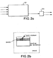
- FIG. 1 illustrates functionally an estimation processor
- the processor 101 includes a RISC controller 102 (RISC meaning: "Reduced Instruction Set Computer”), a network coprocessor systolic 103, three independent input ports 104, 105, 106 for charging the images, an output port 107 to provide motion vectors, as well only a local RAM and a ROM (referenced respectively by 108 and 109).
- RISC controller 102 RISC meaning: "Reduced Instruction Set Computer”
- network coprocessor systolic 103 three independent input ports 104, 105, 106 for charging the images
- an output port 107 to provide motion vectors
- a local RAM and a ROM referenced respectively by 108 and 109.
- each port of entry is equipped with a subsampling circuit for the implementation of a hierarchical motion estimation.
- the different subsets mentioned communicate through a data bus 111 which is inter alia connected to an external memory DRAM 110.
- a memory management unit 112 regulates the flow of data between local memories.
- the data corresponding to the images (reference or current) are routed to the dynamic memory 110. They are then reread to be submitted in time to the coprocessor 103.
- the vector motion calculated by the coprocessor 103 are returned to the memory dynamic 110 through a buffer BUFF 114. At the moment timely, these vectors are replayed and transmitted via the output port 107.
- the processor 101 is also provided with a microprocessor interface 115 for programming and configuring the controller RISC 102, by downloading code and calculation parameters.
- the vectors motion stored in dynamic memory 110 are also accessible through the interface 115.
- a MAX-AVR 113 unit calculates the average motion vector and the maximum motion vector for each image.
- the RISC controller 102 is, according to the present example, a processor with 19 bits with 62 registers and a data memory of 64 words.
- the role of the controller 102 is to manage the requests of the various units of the processor 101 and activate them in a timely manner.
- the RISC controller 102 is connected to the local RAM 108 and the ROM local 109, the latter containing commonly used routines.
- Figure 2a illustrates the flow of information in the network Systolic.
- the basic function of the network is to compare a block of pixels current to the contents of a reference window.
- the current block is stored in the systolic network 201.
- the reference window is conveyed in strips to the network.
- the error function Err is calculated.
- a element 202 determines the smallest value of the error function and the vector corresponding movement.
- FIG. 2b illustrates the method of determining which bands to provide to the systolic network.
- Each band has a number of lines of pixels that corresponds to the number of lines of the network (4 according to this example).
- the first band contains the first four lines of the reference window.
- the treatment is continued with the next band, which contains the last three lines of the first band, as well as the line immediately following this first band.
- Each band is thus shifted by one line with respect to the previous band.
- Each band is supplied to the systolic network column by column.
- the current block having the same number of lines as each band, is thus compared to all blocks of the same size of each band. Finally, the block current will have been compared to all blocks of the same size of the window of reference.
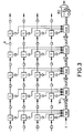
- FIG. 3 illustrates a systolic array of four lines and five columns.
- This network comprises so-called “S” cells, "B” buffers, adders "Add”, bypass cells 301 and a bypass cell final 302.
- S cells execute the calculation
- the output of each cell S of the same line is connected by a buffer B to the input of the next S cell.
- a buffer B is also present in front of each first cell S of a line.
- the values of pixels b propagate from a buffer to a next buffer on the same line at each cycle. Buffers maintain the values b while the S cells perform their calculations.
- Each cell S also has an output C, which provides the result of the operation
- the outputs C are also connected to buffers B. All the buffers B of the same column are connected to the same adder Add. There is therefore as many adders as columns.
- the output of an adder is connected to the input of the adder next by three buffers B in series. Depending on the mode of operation chosen, last of these three buffers is or is not short-circuited by a bypass cell 301.
- the final derivation cell provides either a value of the function of error at each cycle in normal non-interlaced operation, a value of the error function every two cycles in interlaced mode.
- the adder integrated in this final bypass cell 302 adds up two consecutive values of the error function.
- the adders Add are made to using three-input holdback save adders ("Three input carry save adders ")
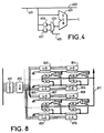
- FIG. 4 shows in more detail the functions of an S cell.
- cell S comprises an input 401, an output 402 connected directly to the input 401, a computing unit 403 having two inputs one of which is connected to the input 401 and the other at the output of a multiplexer 404 allowing select through a selection line 405 the content of a buffer 406, which is the content of a buffer 407.
- the entries of buffers 406 and 407 are also connected to the input 401 of the cell.
- Each of the two buffers contains a pixel value of a block current. These values are loaded through the input 401 at the appropriate time.
- the control circuits of the buffers are classic and will not be illustrated more in detail.
- the presence in parallel of two buffers allows others to at the same time store two common blocks in a single systolic array. Thus, two comparisons can be made for the same position in the reference window. This reduces the amount of data transiting between the dynamic memory 10 and the coprocessor 3.
- the calculation unit provides the absolute value of the difference of the two values present at its entries.
- the values b of the pixels of the reference window are stored in the buffers B between the cells S, while the values has pixels of the current block or blocks are stored in the buffers of the S cells
- This accumulation function conditions the delay introduced by the buffers 504 between the adders. It is easy to see that we have to introduce a delay by two cycles so that the propagation of results at the level of adders is done properly. This explains the presence of two buffers between each adder. Each buffer introduces a delay of one cycle. Said another way, the two buffers 504 and 505 between the first two adder cancel the delay introduced by the buffers 501 and 502.
- the value of the function Err for the first possible position of the current block is present at the output 506 of the network.
- Figure 6 and Table 7 illustrate the operation of a network systolic in interlaced mode. This mode is used to determine functions of error for common blocks with a number of lines equal to twice the number of lines of the systolic network. This is done simply by adding an extra buffer in each S cell and a buffer additional between each adder.
- FIG. 6 is similar to FIG. 5, except that a buffer additional is inserted between each pair of adders.
- each cell S has the two internal buffers illustrated in FIG. During even cycles, the contents of the first buffer of each S cell is multiplexed to the corresponding computing unit, while the content of the second buffer is used in odd cycles.
- the current block of double size is separated into two sub-blocks a and a ' vertically stacked.
- the first sub-block a is stored in the first buffers of each cell S, while the second sub-block a 'is stored in the second buffers of each S cell.
- the reference window strip has an identical number of lines doubled. It comprises an upper sub-band b and a lower sub-band b '. During an even cycle, a column of the sub-band b is presented at the entrance of the systolic network, while a column of b 'is presented during odd cycles.
- Table 2 gives the status of the outputs c after each cycle. Similarly than previously, the bold characters indicate the intermediate results that will have to add up to form an error function corresponding to a sub-block.
- the last adder 601 of the network of FIG. 6 is connected on the one hand at a first input of an adder 602, on the other hand to a buffer 603 whose the output is connected to the second input of the adder 602.
- the error function corresponding to a sub-block is provided to the output of the adder 601 at each cycle (once the network is correctly initialized).
- Table 2 shows that the error function value corresponding to the sub-block a 'is delayed by one cycle to that corresponding to sub-block a. he add the two values to obtain the value of the error function corresponding to the entire block a + a '.
- the value corresponding to a is stored in the buffer 603.
- the value corresponding to the block a ' is present at the output of the adder 601.
- the adder 602 performs the sum. A valid result is therefore present at the output of the adder 602 every two cycles.
- the systolic network is designed to process current blocks having a number of lines equal to N times the number of lines of the network, where N is an integer greater than 2.
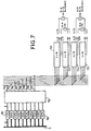
- FIG. 7 schematically represents the coprocessor following a first variant of the exemplary embodiment.
- the coprocessor includes ten first-in-first-out (FIFO) stacks 701 to 710, connected in parallel on the data bus 11.
- the number of words of FIFO data determines the number of pixel columns in the window of research.
- the outputs of the batteries 701 to 710 are connected to a circuit of switching 712 having ten inputs and eight outputs 714 to 721.
- the circuit 712 makes it possible to connect the output of any of the ten FIFOs on any of the eight outputs of the circuit.
- Each FIFO contains an entire line of the search window.
- the eight FIFOs connected to one output at a given moment correspond to the lines of the strip of the window of processed search.
- the two additional unconnected FIFOs are loaded by via the data bus from the data stored in the memory 10.
- the loaded data corresponds to the lines of the search window which differ from the bands being processed.
- the first band of eight lines L1 to L8 a search window is contained in the FIFOs 701 to 708.
- line L9 is loaded into FIFO 709.
- the second band contains lines L2 to L9. The processing of this second band can therefore start without a dead time, since the complete band is present in the FIFOs.
- the circuit of switching will have charge to restore the proper order of stored lines before presentation to systolic networks 722 to 725.
- the bands have eight lines, nine FIFOs are sufficient for the described operation.
- the tenth FIFO is used for example when treats two strips of four lines in parallel.
- four systolic networks 722 to 725 of four lines and sixteen columns each are connected to the outputs of the circuit of commutation.
- the output 714 represents the line greater than one band of eight lines
- output 721 represents the line lower.
- the first and third networks (respectively 722 and 724) are connected to the four upper outputs 714 to 717, while the second and fourth network (respectively 723 and 725) are connected to the four lower outputs 718 to 721.
- the networks work in interlaced mode, only eight outlets being available and not sixteen.
- the eight outings will provide alternatively columns of eight pixels of an upper band and a lower band of the reference window.
- the depth of the FIFOs determines the width of the reference window.
- Figure 7 shows on the other hand in the form of arrows how to group the calculation results at the output of each network of 4 * 16 elements according to the mode of operation.
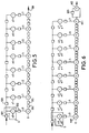
- FIG. 8 illustrates a second variant of the exemplary embodiment.
- Nine FIFOs (grouped as 801) feed a circuit of 802.
- the coprocessor according to the present example comprises eight systolic networks 803 to 810 of 4 * 8 elements.
- two 4 * 8 networks in cascade of Figure 8 equivalent to a 4 * 16 network of Figure 7.
- Figure 8 to better illustrate the flow of the calculation results of each of the networks when eight current blocks of 4 * 8 are processed in parallel. Example will be taken on the two upper networks 803 and 804.
- the final result (this is at tell the value of the error function) at the output of the network 803 is transmitted directly to the 804 network.
- an M cell is associated with each network of 4 * 8 elements.
- Each cell M determines the minimum value the error function at the output of one of the networks, and remembers the coordinates of the corresponding motion vector.
- the results are communicated through a specific data bus 811.
- the outputs of the networks 803, 804, 807 and 808 are connected each at the input of a two-input multiplexer, the output of which is connected to the input of the associated cell M.
- the output of each of the same networks is also connected to the input of a two-input adder that receives on its other input the output of the network immediately below.
- 803 networks, 804, 807 and 808, these are respectively the outputs of the networks 805, 806, 809 and 810.
- each network When the processor is working on eight current blocks, the output of each network is directly connected to the associated cell M. Each cell M then autonomously determines the minimum value of the error function and the movement vector. This results in eight distinct vectors.
- the multiplexers switch so that one of the associated M cells with two overlapping networks working on the same block receives the sum of the values error functions calculated by these two networks. Only the determined vector by the cell receiving this sum will be taken into account later.
- the switching of the multiplexers is controlled by the controller 2 of Figure 1.
Landscapes
- Engineering & Computer Science (AREA)
- Multimedia (AREA)
- Signal Processing (AREA)
- Computer Vision & Pattern Recognition (AREA)
- Physics & Mathematics (AREA)
- General Physics & Mathematics (AREA)
- Theoretical Computer Science (AREA)
- Compression Or Coding Systems Of Tv Signals (AREA)
- Compression, Expansion, Code Conversion, And Decoders (AREA)
Applications Claiming Priority (2)
| Application Number | Priority Date | Filing Date | Title |
|---|---|---|---|
| FR9410158A FR2723796B1 (fr) | 1994-08-19 | 1994-08-19 | Dispositif d'estimation de mouvement |
| FR9410158 | 1994-08-19 |
Publications (2)
| Publication Number | Publication Date |
|---|---|
| EP0702327A1 EP0702327A1 (fr) | 1996-03-20 |
| EP0702327B1 true EP0702327B1 (fr) | 2005-08-17 |
Family
ID=9466402
Family Applications (1)
| Application Number | Title | Priority Date | Filing Date |
|---|---|---|---|
| EP95401910A Expired - Lifetime EP0702327B1 (fr) | 1994-08-19 | 1995-08-18 | Dispositif d'estimation de mouvement |
Country Status (9)
| Country | Link |
|---|---|
| US (1) | US5745605A (zh) |
| EP (1) | EP0702327B1 (zh) |
| JP (1) | JPH0879761A (zh) |
| KR (1) | KR100437177B1 (zh) |
| CN (1) | CN1110209C (zh) |
| BR (1) | BR9503709A (zh) |
| DE (1) | DE69534380D1 (zh) |
| FR (1) | FR2723796B1 (zh) |
| MY (1) | MY122561A (zh) |
Families Citing this family (6)
| Publication number | Priority date | Publication date | Assignee | Title |
|---|---|---|---|---|
| FR2742248B1 (fr) * | 1995-12-06 | 1998-01-23 | Thomson Multimedia Sa | Procede de traitement de donnees dans des reseaux matriciels dans un systeme d'estimation de mouvement |
| US5953458A (en) * | 1995-12-06 | 1999-09-14 | Thomson Multimedia S.A. | Method and device for motion estimation |
| US6115837A (en) * | 1998-07-29 | 2000-09-05 | Neomagic Corp. | Dual-column syndrome generation for DVD error correction using an embedded DRAM |
| CN100356780C (zh) * | 2005-02-03 | 2007-12-19 | 清华大学 | 用于压缩视频信号解码的图像存储方法 |
| US20070150697A1 (en) * | 2005-05-10 | 2007-06-28 | Telairity Semiconductor, Inc. | Vector processor with multi-pipe vector block matching |
| US20060259737A1 (en) * | 2005-05-10 | 2006-11-16 | Telairity Semiconductor, Inc. | Vector processor with special purpose registers and high speed memory access |
Family Cites Families (9)
| Publication number | Priority date | Publication date | Assignee | Title |
|---|---|---|---|---|
| DE3721074A1 (de) * | 1986-12-24 | 1988-07-07 | Licentia Gmbh | Schaltungsanordnung zur verschiebungsvektorsuche in der digitalen bildanalyse |
| US4897720A (en) * | 1988-03-14 | 1990-01-30 | Bell Communications Research, Inc. | Circuit implementation of block matching algorithm |
| FR2638924B1 (fr) * | 1988-11-09 | 1991-01-25 | Artieri Alain | Procede et circuit de traitement par bloc de signal bidimensionnel d'images animees |
| US4902849A (en) * | 1989-02-06 | 1990-02-20 | Phillips Petroleum Company | Dehydrogenation process |
| GB8909498D0 (en) * | 1989-04-26 | 1989-06-14 | British Telecomm | Motion estimator |
| JPH0385884A (ja) * | 1989-08-29 | 1991-04-11 | Sony Corp | 画像の動き検出回路 |
| US4937666A (en) * | 1989-12-04 | 1990-06-26 | Bell Communications Research, Inc. | Circuit implementation of block matching algorithm with fractional precision |
| KR0160618B1 (ko) * | 1992-10-27 | 1999-01-15 | 윤종용 | 실시간 움직임 추정장치 및 그 방법 |
| DE69327040T2 (de) * | 1993-02-22 | 2000-04-13 | Industrial Technology Research Institute, Chutung | Blockübereinstimmungsarchitektur mit mehreren Modulen |
-
1994
- 1994-08-19 FR FR9410158A patent/FR2723796B1/fr not_active Expired - Fee Related
-
1995
- 1995-08-04 US US08/511,483 patent/US5745605A/en not_active Expired - Fee Related
- 1995-08-17 CN CN95115290A patent/CN1110209C/zh not_active Expired - Fee Related
- 1995-08-18 DE DE69534380T patent/DE69534380D1/de not_active Expired - Lifetime
- 1995-08-18 EP EP95401910A patent/EP0702327B1/fr not_active Expired - Lifetime
- 1995-08-18 JP JP7210855A patent/JPH0879761A/ja active Pending
- 1995-08-18 MY MYPI95002439A patent/MY122561A/en unknown
- 1995-08-18 BR BR9503709A patent/BR9503709A/pt not_active IP Right Cessation
- 1995-08-18 KR KR1019950025805A patent/KR100437177B1/ko not_active IP Right Cessation
Also Published As
| Publication number | Publication date |
|---|---|
| MY122561A (en) | 2006-04-29 |
| CN1110209C (zh) | 2003-05-28 |
| BR9503709A (pt) | 1996-05-28 |
| DE69534380D1 (de) | 2005-09-22 |
| FR2723796A1 (fr) | 1996-02-23 |
| FR2723796B1 (fr) | 1996-11-29 |
| CN1119815A (zh) | 1996-04-03 |
| KR100437177B1 (ko) | 2004-10-20 |
| EP0702327A1 (fr) | 1996-03-20 |
| US5745605A (en) | 1998-04-28 |
| KR960009753A (ko) | 1996-03-22 |
| JPH0879761A (ja) | 1996-03-22 |
Similar Documents
| Publication | Publication Date | Title |
|---|---|---|
| EP0369854B1 (fr) | Procédé et circuit de traitement par bloc de signal bidimensionnel d'images animées | |
| EP0717372B1 (fr) | Procédé de sélection de vecteurs de mouvement et dispositif de traitement d'images mettant en oeuvre ledit procédé | |
| EP0406074B1 (fr) | Procédé de segmentation du champ de mouvement d'une image pour le codage d'images vidéo | |
| EP0492702B1 (fr) | Dispositif de correlation | |
| EP0778544B1 (fr) | Procédé de traitement de données dans des réseaux matriciels dans un système d'estimation de mouvement | |
| US20010028681A1 (en) | Motion estimator | |
| FR2760580A1 (fr) | Systeme de codage et decodage mpeg pour des applications multimedia | |
| US20150147005A1 (en) | Methods and apparatus for image processing at pixel rate | |
| FR2738364A1 (fr) | Procede et processeur de transformation cosinusoidale discrete inverse | |
| EP0680220A1 (fr) | Dispositif et procédé d'adressage d'une mémoire cache d'un circuit de compression d'images mobiles | |
| EP0702327B1 (fr) | Dispositif d'estimation de mouvement | |
| EP0722251B1 (fr) | Procédé d'interpolation d'images | |
| WO2004100557A2 (fr) | Procede et dispositif de codage ou decodage d’image avec parallelisation du traitement sur une pluralite de processeurs, programme d’ordinateur et signal de synchronisation correspondants | |
| EP1246469A2 (fr) | Procédé de réduction de format et de décodage similtanés de signaux vidéo codés | |
| EP0286192B1 (fr) | Procédé et dispositif d'estimation de mouvement dans une séquence d'images | |
| EP1246471A1 (fr) | Dispositif implémentant conjointement un post-traitement et un décodage de données | |
| EP0674444B1 (fr) | Filtre de matrices de pixels | |
| EP2364552B1 (fr) | Dispositif d'encodage d'un flux d'images numeriques et dispositif de decodage correspondant avec approximation du voisinage d'un bloc par le voisinage élargi du bloc | |
| EP1679899A1 (fr) | Procédé et dispositif de réduction des artefacts d'une image numérique | |
| EP0778545B1 (fr) | Procédé et dispositif d'estimation de mouvement | |
| EP0676114B1 (fr) | Dispositif d'estimation hierarchique du mouvement de sequence d'images | |
| WO2011131903A1 (fr) | Procede de traitement d'une information de mouvement et procedes de codage | |
| FR2962291A1 (fr) | Procede de traitement d'images 3d, et systeme correspondant | |
| FR3103302A1 (fr) | Segmentation d'images par flot optique | |
| FR2761553A1 (fr) | Procedes et dispositifs de traitement d'un ensemble de donnees et notamment de compression et de decompression de donnees d'images |
Legal Events
| Date | Code | Title | Description |
|---|---|---|---|
| PUAI | Public reference made under article 153(3) epc to a published international application that has entered the european phase |
Free format text: ORIGINAL CODE: 0009012 |
|
| AK | Designated contracting states |
Kind code of ref document: A1 Designated state(s): DE FR GB IT |
|
| 17P | Request for examination filed |
Effective date: 19960518 |
|
| RAP1 | Party data changed (applicant data changed or rights of an application transferred) |
Owner name: THOMSON MULTIMEDIA |
|
| 17Q | First examination report despatched |
Effective date: 19990910 |
|
| GRAG | Despatch of communication of intention to grant |
Free format text: ORIGINAL CODE: EPIDOS AGRA |
|
| GRAG | Despatch of communication of intention to grant |
Free format text: ORIGINAL CODE: EPIDOS AGRA |
|
| GRAP | Despatch of communication of intention to grant a patent |
Free format text: ORIGINAL CODE: EPIDOSNIGR1 |
|
| GRAU | Approval following communication of intention to grant |
Free format text: ORIGINAL CODE: EPIDOSNAGR4 |
|
| GRAS | Grant fee paid |
Free format text: ORIGINAL CODE: EPIDOSNIGR3 |
|
| GRAA | (expected) grant |
Free format text: ORIGINAL CODE: 0009210 |
|
| AK | Designated contracting states |
Kind code of ref document: B1 Designated state(s): DE FR GB IT |
|
| PG25 | Lapsed in a contracting state [announced via postgrant information from national office to epo] |
Ref country code: GB Free format text: LAPSE BECAUSE OF FAILURE TO SUBMIT A TRANSLATION OF THE DESCRIPTION OR TO PAY THE FEE WITHIN THE PRESCRIBED TIME-LIMIT Effective date: 20050817 |
|
| PGFP | Annual fee paid to national office [announced via postgrant information from national office to epo] |
Ref country code: DE Payment date: 20050817 Year of fee payment: 11 |
|
| REG | Reference to a national code |
Ref country code: GB Ref legal event code: FG4D Free format text: NOT ENGLISH |
|
| RIN1 | Information on inventor provided before grant (corrected) |
Inventor name: PAUL, PHILIPPE Inventor name: BARD, JEAN-MICHEL Inventor name: PIRSON, ALAIN |
|
| PGFP | Annual fee paid to national office [announced via postgrant information from national office to epo] |
Ref country code: GB Payment date: 20050818 Year of fee payment: 11 |
|
| PGFP | Annual fee paid to national office [announced via postgrant information from national office to epo] |
Ref country code: FR Payment date: 20050825 Year of fee payment: 11 |
|
| REF | Corresponds to: |
Ref document number: 69534380 Country of ref document: DE Date of ref document: 20050922 Kind code of ref document: P |
|
| PG25 | Lapsed in a contracting state [announced via postgrant information from national office to epo] |
Ref country code: DE Free format text: LAPSE BECAUSE OF FAILURE TO SUBMIT A TRANSLATION OF THE DESCRIPTION OR TO PAY THE FEE WITHIN THE PRESCRIBED TIME-LIMIT Effective date: 20051118 |
|
| GBV | Gb: ep patent (uk) treated as always having been void in accordance with gb section 77(7)/1977 [no translation filed] |
Effective date: 20050817 |
|
| PLBE | No opposition filed within time limit |
Free format text: ORIGINAL CODE: 0009261 |
|
| STAA | Information on the status of an ep patent application or granted ep patent |
Free format text: STATUS: NO OPPOSITION FILED WITHIN TIME LIMIT |
|
| 26N | No opposition filed |
Effective date: 20060518 |
|
| PGFP | Annual fee paid to national office [announced via postgrant information from national office to epo] |
Ref country code: IT Payment date: 20060831 Year of fee payment: 12 |
|
| REG | Reference to a national code |
Ref country code: FR Ref legal event code: ST Effective date: 20070430 |
|
| PG25 | Lapsed in a contracting state [announced via postgrant information from national office to epo] |
Ref country code: FR Free format text: LAPSE BECAUSE OF NON-PAYMENT OF DUE FEES Effective date: 20060831 |
|
| PG25 | Lapsed in a contracting state [announced via postgrant information from national office to epo] |
Ref country code: IT Free format text: LAPSE BECAUSE OF NON-PAYMENT OF DUE FEES Effective date: 20070818 |