EP0702245B1 - Verfahren zur Befreiung von Körperschallstörungen - Google Patents
Verfahren zur Befreiung von Körperschallstörungen Download PDFInfo
- Publication number
- EP0702245B1 EP0702245B1 EP95113745A EP95113745A EP0702245B1 EP 0702245 B1 EP0702245 B1 EP 0702245B1 EP 95113745 A EP95113745 A EP 95113745A EP 95113745 A EP95113745 A EP 95113745A EP 0702245 B1 EP0702245 B1 EP 0702245B1
- Authority
- EP
- European Patent Office
- Prior art keywords
- borne sound
- coherence
- spectrum
- spectra
- determined
- Prior art date
- Legal status (The legal status is an assumption and is not a legal conclusion. Google has not performed a legal analysis and makes no representation as to the accuracy of the status listed.)
- Expired - Lifetime
Links
Images

Classifications
-
- G—PHYSICS
- G01—MEASURING; TESTING
- G01S—RADIO DIRECTION-FINDING; RADIO NAVIGATION; DETERMINING DISTANCE OR VELOCITY BY USE OF RADIO WAVES; LOCATING OR PRESENCE-DETECTING BY USE OF THE REFLECTION OR RERADIATION OF RADIO WAVES; ANALOGOUS ARRANGEMENTS USING OTHER WAVES
- G01S3/00—Direction-finders for determining the direction from which infrasonic, sonic, ultrasonic or electromagnetic waves, or particle emission, not having a directional significance, are being received
- G01S3/80—Direction-finders for determining the direction from which infrasonic, sonic, ultrasonic or electromagnetic waves, or particle emission, not having a directional significance, are being received using ultrasonic, sonic or infrasonic waves
- G01S3/86—Direction-finders for determining the direction from which infrasonic, sonic, ultrasonic or electromagnetic waves, or particle emission, not having a directional significance, are being received using ultrasonic, sonic or infrasonic waves with means for eliminating undesired waves, e.g. disturbing noises
Definitions
- the invention relates to a method for exemption from Structure-borne noise in reception signals from a Acoustic DF system in the preamble of claim 1 Art.
- reception systems with a Variety of electroacoustic transducers on one Carrier vehicle for example a submarine or Surface ship built to target, e.g. B. Ships, submarines or torpedoes, due to their driving noise direction.
- B. Ships e.g. B. Ships
- Your Vibrations cause in the walls of the Carrier vehicle structure-borne noise, which is also in the water is emitted.
- the electroacoustic transducers of the Receiving system received over the wall and over that Water the structure-borne noise and at the same time sound waves that are emitted from the targets to be located.
- the reception structure-borne noise leads to errors in the bearing.
- received signals are one electro-acoustic transducer of a DF system of such unwanted signal components freed.
- On Structure-borne noise sensor that is close to the structure-borne noise-causing aggregates is arranged and receives interference alone, provides a reference interference signal. It becomes the cross-correlation function or the complex one Cross spectrum between the received signals and the Reference interference signals formed and from it Correction signal obtained and in phase from Received signal subtracted.
- the correction signal is obtained characterized in that frequency components of the reference interference signal by Filter banks are separated and with the receive signal be correlated.
- DE 35 20 398 A describes a method for the exemption from Known structure-borne noise, in which to determine a spectral correspondence between received signals and Structure-borne noise signals from the received signal a complex Reception spectrum and from the structure-borne sound signal complex structure-borne noise spectrum are formed.
- Reception spectrum and structure-borne noise spectrum are divided, the quotient denotes the transfer function for Structure-borne noise from its source to the electro-acoustic Converter.
- the time average of the transfer function is formed to prevent short-term sound events, e.g. B. at Reception of sonar pulses, in the reception spectrum to average, so that the transfer function alone that Specifies transmission behavior for structure-borne noise.
- the mean value of the transfer function is calculated with the Structure-borne noise spectrum multiplied and by the reception spectrum deducted so that structure-borne noise is suppressed safely without bearing with the same frequency To affect useful signal components.
- Sound sources e.g. Surface ships or submarines, for example from a submarine a variety of Hydrophones along a line or area on the Arranged outer wall of the submarine. You get through it a wide-ranging reception arrangement.
- the through Directional characteristic resulting from the summation of the received signals has an opening angle that is very small as it passes through the longitudinal and / or transverse extension of the receiving system is determined. By appropriate direction formation can this directional characteristic in many predeterminable directions be generated pointing or pivoting. From a far distant sound source, for example a moving one Ship, sound waves are emitted. You reach the Reception system as flat wave fronts, which depend on have fixed phase relationships in the direction of incidence.
- phase relationships are used for the bearing of the Sound source compensated in the direction formation. Changes the relative position between the sound source and Receiving system, the phase relationships also change and thus the bearing.
- time intervals are bearing and phase relationships constant, i.e. the incident sound waves are coherent. about the phase relationships fluctuate over several time intervals however, because, for example, the target to be located or the Carrier vehicle of the receiving system change their position to each other.
- Sources of interference for structure-borne noise are just as local firmly attached to the carrier vehicle like that electroacoustic transducer of the receiving system, so that Structure-borne sound propagation paths and thus Transmission properties for structure-borne noise unchanged are. It follows that in periods in which the causing aggregates same operating condition have the received structure-borne sound waves at all Receiving locations have the same properties with respect to each other Have frequency and phase position, i.e. are coherent.
- the operating status of the units does not change from Time interval to time interval in which each bearing already change, i.e. the temporal length of the same coherent state is greater than for structure-borne noise signals for the part of the received signals that is to be located by the Sound target originates.
- the method according to the invention makes use of this fact by the temporal coherence between received signals and Structure-borne noise is examined and those Frequency components in the received signal are suppressed, the Coherence demonstrable over a predefinable period of time is.
- Frequency lines in the received signal, from the target and through Structure-borne noise is caused by the Assessment with coherence only according to your Structure-borne noise suppressed in the received signal, one Bearing evaluation is retained because the proportion of received by the target, not coherent in the time period is, but has changed in its phase and thus not in the coherence determination for the time period comes in.
- the advantage of the method according to the invention Claim 1 is that in the reception frequency spectrum all frequency components that radiated from the target alone were used for the bearing to the target while the frequency components that would distort the bearing there they are caused by your own drive units, be hidden. So it's a strict separation between useful and interference signal at the same frequency possible. Even the smallest DF changes are made by the Noise suppression not averaged out, so that with a Tracking no temporary goal loss occurs and the bearing to the destination can always be specified.
- Another advantage is that for the Carrier vehicle only the drive units during the must have the same operating status over time, that changing the course of the carrier vehicle not only allows but are advantageous because they lead to DF changes and thus contribute to phase changes of the useful signal.
- This Changes in course can be caused by currents in the Water, by drifting the carrier vehicle and not only occur through steering maneuvers.
- the period is the same Time intervals divided and complex per time interval Reception spectra and structure-borne noise spectra formed and to Sum spectra summed up. Also be Range of services from the complex reception and Structure-borne noise spectra determined and during the Period summed up. From the so obtained summed cross spectra and power spectra is for the coherence between each electroacoustic transducer its received signal and the structure-borne noise signals of everyone Structure-borne noise sensors determined.
- the special advantage is that the time interval and time period are free are selectable and the overall situation in which the target is located individually during a mission can be adjusted.
- the Coherence function After further training of the to calculate the inventive method according to claim 3.
- the coherence function the quotient of the conjugate complex product of the summed cross spectra and the product of the summed up performance spectrum of Received signal and structure-borne sound signal formed.
- the Coherence function has a value between 1 and 0.
- reception signals and structure-borne noise signals are strict are coherent, their value is 1 if they are not rigid Have phase relationship to each other, their value is the same 0.
- the particular advantage of one such signal processing is that Standard building blocks of computer technology are used can, the use of which is unproblematic.
- the method of claim 4 is for everyone Structure-borne noise signal determined coherence function with the sum standardized the coherence function of all structure-borne noise signals. Every structure-borne noise spectrum is standardized with its Coherence function multiplied and the structure-borne noise adapted in the reception spectrum.
- Method according to claims 5 and 6 is the normalized Coherence function with a transfer function of the Structure-borne noise from each structure-borne noise sensor to electro-acoustic transducer whose reception spectrum to be suppressed, multiplied.
- the frequency dependent Transfer function is equal to that added up Cross spectrum related to the summed Power spectrum of the structure-borne sound signal, which is already in the Connection with the determination of the coherence function were determined.
- the product of the transfer function and normalized coherence function is a weight function for every structure-borne noise spectrum. The so weighted Structure-borne noise spectra are subtracted from the reception spectrum.
- the advantage is that the frequency-dependent complex transfer function the properties of the Transmission path for structure-borne noise from Structure-borne noise sensor for the electro-acoustic transducer DF system are taken into account, regardless of whether the Structure-borne noise over the wall of the carrier vehicle was transmitted or emitted to the surrounding medium and from the electroacoustic transducer together with the Useful signal was received.
- Theoretical investigations Basics, studies and simulations on different Propagation paths of structure-borne noise from the aggregate to electroacoustic transducers in all common Operating states are superfluous because the weight function for every time period when using the receiving system can be measured and determined. An additional effort Computing capacity on board the carrier vehicle is only low.
- the particular advantage of this measure is in that frequency lines in the reception spectrum that go from Target sound waves emitted belong even if they are the have the same frequency as frequency lines in Structure-borne noise spectrum, not to be extinguished, but only by the proportion caused by structure-borne noise downsized, so be free of interference.
- the invention is based on one in the drawing illustrated embodiment for an acoustic Receiving system with several electroacoustic transducers and Structure-borne noise sensors described in more detail.
- structure-borne noise e.g. B. pumps
- y Structure-borne noise sensors 20.1, 20.2, ..., 20.m (y 1, ..., m)
- structure-borne noise sensors 20.1, 20.2, ..., 20.m
- y 1, ..., m
- B. Accelerometer arranged.
- a frequency analysis circuit 30.1, and each structure-borne noise sensor 20.1, ..., 20.m is followed by an FFT analyzer 40.1, ..., 40.m to determine the complex reception spectrum F 10.1 (f, t) the received signal at the electroacoustic transducer 10.1 and the complex structure-borne noise spectra F 20.1 (f, t), F 20.2 (f, t), ..., F 20.m (f, t) of structure-borne noise signals from structure-borne noise sensors 20.1, ..., 20.m per time interval t r .
- Each FFT analyzer 40.1, 40.2, ...., 40.m is followed by an evaluation computer 100.1, 100.2, ..., 100.m, in which the reception spectrum F 10.1 at the output of the frequency analysis circuit 30.1 with the structure-borne sound spectrum F 20.y one of the structure-borne noise sensors 20.1, 20.2, ..., 20.m is compared, the coherence between the reception spectrum F 10.1 and the structure-borne noise spectrum F 20.y is determined and the structure-borne noise spectrum F 20.y is evaluated.
- a tect generator 41 controls the frequency analysis circuit 30.1, the FFT analyzers 40.1, 40.2, ..., 40.m and the evaluation computers 100.1, 100.2, 100.m for each predeterminable time interval t r .
- a time segment T can be set in the clock generator 41, which comprises q time intervals t r .
- Each evaluation computer 100.1, 100.2, 100.m contains coherence computing circuits 50.1, ..., 50.m for calculating the coherence functions ⁇ 2 / xy between the received signal at the electroacoustic transducer 10.1 and the structure-borne noise signals at the structure-borne noise sensors 20.1, ..., 20.m .
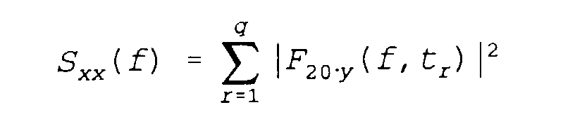
- Power spectra of the reception spectrum F 10.x (f, t r ) are formed and summed up over time and power spectra of the structure-borne noise spectrum F 20.y (f, t r ) are formed and summed up over time t r
- the coherence circuits 50.1, 50.2, ... 50.m are controlled by the clock generator 41.
- Calculation stages 70.1, ..., 70.m for calculating the frequency-dependent transmission function ÜF 1y (f) between the structure-borne noise sensors 20.1, ..., 20.m and the electroacoustic transducer 10.1 are the frequency analysis circuit 30.1 and the FFT analyzers 40.1, .. ., 40.m downstream.
- the transfer function ÜF 1y (f) is equal to the quotient of cross spectra ⁇ xy summed up over the time period T divided by the summed up power spectra S yy of the structure-borne sound spectrum F 20.y.
- BB xy ( f ) ⁇ xy ( f ) S yy ( f )
- the components for determining the summed cross spectra ⁇ xy and power spectra S xx and S yy are used by the coherence arithmetic circuits 50.1, ..., 50.m and the arithmetic stages 70.1, ..., 70.m to calculate the coherence functions ⁇ 2 / xy and shared the transfer function ÜF xy .
- the coherence function ⁇ 2 / xy In weight function arithmetic stages 80.1, ..., 80.m, the coherence function ⁇ 2 / xy , its sum and the transfer function ÜF xy a frequency-dependent weight function calculated and multiplied by the structure-borne noise spectrum F 20y .
- Each structure-borne sound spectrum F 20.y therefore includes an evaluation computer 100.1, ..., 100.m, which consists of a coherence circuit 50.1 or 50.2, ... or 50.m, a computing stage 70.1 or 70.2, ... or . 70.m and a weight function calculation level 80.1 or 80.2, ... or 80.m. All evaluation computers 100.1, 100.2, ..., 100.m and the frequency analysis circuit 30.1 are connected to a subtraction circuit 90 in which the structure-borne noise spectra F 20.y multiplied by the weight function G 1y are subtracted from the reception spectrum F 10.1 (f, t r ) . At the output of the subtraction circuit 90, the reception spectrum F 10.1 of the electroacoustic transducer 10.1 freed from structure-borne noise appears, from which the interference-free reception signal can be determined by transforming back into the time domain.
Landscapes
- Physics & Mathematics (AREA)
- Engineering & Computer Science (AREA)
- General Physics & Mathematics (AREA)
- Radar, Positioning & Navigation (AREA)
- Remote Sensing (AREA)
- Measurement Of Velocity Or Position Using Acoustic Or Ultrasonic Waves (AREA)
- Measurement Of Mechanical Vibrations Or Ultrasonic Waves (AREA)
Description




Claims (10)
- Verfahren zur Befreiung von Körperschallstörungen bei Empfangssignalen einer akustischen Peilanlage mit mehreren elektroakustischen Wandlern, die auf oder vor einem körperschallführenden Träger angeordnet sind und mindestens einem Körperschallsensor, der in der Nähe von körperschallverursachenden Aggregaten angeordnet ist, durch Bestimmen einer spektralen Übereinstimmung zwischen Empfangssignalen und Körperschallsignalen mittels ihrer komplexen Empfangs- und Körperschallspektren, dadurch gekennzeichnet, daß ein Zeitabschnitt (T) aus mehreren Zeitintervallen (tr) gebildet wird, daß aus den komplexen Empfangsspektren und Körperschallspektren je Zeitintervall komplexe Kreuzspektren zwischen dem Empfangssignal des einen elektroakustischen Wandlers und den Körperschallsignalen aller Körperschallsensoren bestimmt werden, daß die Kreuzspektren eines Zeitabschnitts aufsummiert werden und daraus Kohärenzen zwischen dem Empfangssignal jedes einzelnen elektroakustischen Wandlers (10.x) und den Körperschallsignalen aller Körperschallsensoren (20.1, 20.2, ..., 20.y) bestimmt werden, daß Frequenzanteile im Empfangssignal entsprechend ihrer Kohärenz mit Frequenzanteilen im Körperschallsignal unterdrückt werden.
- Verfahren nach Anspruch 1, dadurch gekennzeichnet, daß aus sämtlichen während des Zeitabschnitts (T) je Zeitintervall (tr) ermittelten komplexen Empfangsspektren (F10.x) Leistungsspektren des Empfangssignals und aus sämtlichen während des Zeitabschnitts (T) ermittelten komplexen Körperschallspektren (F20.y) Leistungsspektren des Körperschallsignals ermittelt werden, daß die Leistungsspektren und Kreuzspektren aufsummiert werden und aus den im Zeitabschnitt aufsummierten Kreuzspektren (σxy) und Leistungsspektren (Sxx, Syy) die Kohärenz zwischen dem Empfangssignal jedes elektroakustischen Wandlers (10.x) in bezug auf alle Körperschallsensoren (20.1, 20.2, ..., 20.m) einzeln ermittelt wird.
- Verfahren nach Anspruch 2, dadurch gekennzeichnet, daß die Kohärenz durch Bilden der Kohärenzfunktionen (γ 2 / xy) ermittelt wird, daß die Kohärenzfunktion (γ 2 / xy)gleich der Summe (σxy) aller konjugiert komplexen Produkte jedes im Zeitabschnitt ermittelten Kreuzspektrums geteilt durch das Produkt der Summe (Sxx, Syy) aller im Zeitabschnitt ermittelten Leistungsspektren des Empfangssignals und des Körperschallsignals ist und daß jedes Körperschallspektrum (F20.y) mit der zugehörigen Kohärenzfunktion (γ 2 / xy) bewertet wird.
- Verfahren nach Anspruch 3, dadurch gekennzeichnet, daß für die Bewertung die Summe sämtlicher Kohärenzfunktionen (γ 2 / xy) über die Anzahl (y) der Körperschallsensoren (20.1, 20.2, ..., 20.m) gebildet wird und alle Kohärenzfunktionen (γ 2 / xy) auf diese Summe bezogen werden.
- Verfahren nach Anspruch 3 oder 4, dadurch gekennzeichnet, daß eine Übertragungsfunktion (ÜFxy) für den Körperschall von jedem Körperschallsensor (20.1, 20.2, ..., 20.m) zum elektroakustischen Wandler (10.x) aus dem Quotienten des aufsummierten Kreuzspektrums (σxy) bezogen auf das aufsummierte Leistungsspektrum (Syy) des Körperschallspektrums ermittelt wird, daß die Übertragungsfunktion (ÜFxy) mit der Kohärenzfunktion (γ 2 / xy) multipliziert wird und eine Gewichtsfunktion (Gxy) zur Bewertung jedes Körperschallspektrums (F20.y) liefert.
- Verfahren nach Anspruch 5, dadurch gekennzeichnet, daß daß Körperschallspektrum (F20.y) jedes Körperschallsignals mit der Gewichtsfunktion (Gxy) multipliziert wird und die so bewerteten Körperschallspektren (Gxy.F20.y)vom Empfangsspektrum (F10.x) abgezogen werden.
- Vorrichtung zum Ausüben des erfindungsgemäßen Verfahrens nach einem der Ansprüche 1 bis 6 unter Verwendung einer Peilanlage mit mehreren elektroakustischen Wandlern, die auf oder vor einem körperschallführenden Träger an Bord eines Trägerfahrzeugs angeordnet sind, und mindestens einem Körperschallsensor, der in der Nähe von Körperschall verursachenden Aggregaten angeordnet ist, wobei jedem elektroakustischen Wandler eine Frequenzanalyseschaltung und jedem Körperschallsensor ein FFT-Analysator nachgeschaltet ist, dadurch gekennzeichnet, daß ein Taktgenerator (41) zum Vorgeben eines Zeitabschnitts (T) vorgesehen ist, daß jede Frequenzanalyseschaltung (30.x) ausgangsseitig mit einer Anzahl Bewertungsrechnern (100.1, 100.2, ..., 100.m), die gleich der Anzahl (m) der Körperschallsensoren (20.1, 20.2, ..., 20.m) ist, verbunden ist, daß die Bewertungsrechner (100.1, 100.2, ..., 100.m) von dem Taktgenerator (41) ansteuerbar sind, daß jeder Bewertungsrechner (100.1, 100.2, ..., 100.m) mit dem Ausgang eines der FFT-Analysatoren (40.1, 40.2, ..., 40.m) verbunden ist zum Bestimmen der Kohärenz zwischen Empfangsspektrum (F10.x(f, t)) und Körperschallspektrum (F20.y(f, t)) und Bewerten jedes Körperschallspektrums (F20.y(f, t)) je Zeitabschnitt (T) und daß die Ausgänge der Bewertungsrechner (100.1, ..., 100.m) und der Ausgang der Frequenzanalyseschaltung (30.x) mit einer Subtraktionsschaltung (90) verbunden sind, an deren Ausgang ein störbefreites Empfangssepktrum des elektroakustischen Wandlers (10.1) je Zeitabschnitt (T) abnehmbar ist und daß für jeden elektroakustischen Wandler (20.2, 20.3, ...) eine gleiche Anzahl von Bewertungsrechnern vorgesehen ist, die jeweils mit einer Subtraktionsschaltung verbunden sind.
- Vorrichtung nach Anspruch 7, dadurch gekennzeichnet, daß jeder Bewertungsrechner (100.1, 100.2, ..., 100.m) eine Kohärenzrechenschaltung (50.1, 50.2, ..., 50.m) zum Berechnen der Kohärenzfunktion (γ 2 / xy) enthält, die mit dem Taktgenerator (41) verbunden ist.
- Vorrichtung nach Anspruch 8, dadurch gekennzeichnet, daß jeder Bewertungsrechner (100.1, 100.2, ..., 100.m) parallel zur Kohärenzrechenschaltung (50.1, ..., 50.m) eine Rechenstufe (70.1, 70.2, ..., 70.m) zum Bestimmen einer Übertragungsfunktion (ÜFyx(f)) enthält.
- Vorrichtung nach Anspruch 9, dadurch gekennzeichnet, daß in jedem Bewertungsrechner (100.1, 100.2, ..., 100.m) die Ausgänge der Kohärenzrechenschaltung (50.1, ..., 50.m) und der Rechenstufe (70.1, ..., 70.m) mit einer Gewichtsfunktionsrechenstufe (80.1, 80.2, ..., 80.m) verbunden sind, daß die Gewichtsfunktionssrechenstufe (80.1, ..., 80.m) mit dem FFT-Analysator (40.1, ..., 40.m) am Eingang des Bewertungsrechners (100.1, ..., 100.m) und mit dem Ausgang einer Summationsschaltung (60) verbunden ist, daß die Summationsschaltung (60) eingangsseitig mit den Kohärenzrechenschaltungen (50.1, 50.2, ..., 50.m) in allen Bewertungsrechnern (100.1, 100.2, ..., 100.m) zusammengeschaltet ist.
Applications Claiming Priority (2)
| Application Number | Priority Date | Filing Date | Title |
|---|---|---|---|
| DE4432532 | 1994-09-13 | ||
| DE4432532A DE4432532A1 (de) | 1994-09-13 | 1994-09-13 | Verfahren zur Befreiung von Körperschallstörungen |
Publications (3)
| Publication Number | Publication Date |
|---|---|
| EP0702245A2 EP0702245A2 (de) | 1996-03-20 |
| EP0702245A3 EP0702245A3 (de) | 1997-11-12 |
| EP0702245B1 true EP0702245B1 (de) | 2000-03-29 |
Family
ID=6528073
Family Applications (1)
| Application Number | Title | Priority Date | Filing Date |
|---|---|---|---|
| EP95113745A Expired - Lifetime EP0702245B1 (de) | 1994-09-13 | 1995-09-01 | Verfahren zur Befreiung von Körperschallstörungen |
Country Status (2)
| Country | Link |
|---|---|
| EP (1) | EP0702245B1 (de) |
| DE (2) | DE4432532A1 (de) |
Families Citing this family (3)
| Publication number | Priority date | Publication date | Assignee | Title |
|---|---|---|---|---|
| DE10136026A1 (de) * | 2001-07-25 | 2003-02-20 | Stn Atlas Elektronik Gmbh | Verfahren zur Bewertung der Kohärenz von Schallwellen |
| DE10136981A1 (de) | 2001-07-30 | 2003-02-27 | Daimler Chrysler Ag | Verfahren und Vorrichtung zur Ermittlung eines stationären und/oder bewegten Objektes |
| DE102020007696A1 (de) | 2020-08-19 | 2022-02-24 | Atlas Elektronik Gmbh | Wasserschallempfänger |
Family Cites Families (9)
| Publication number | Priority date | Publication date | Assignee | Title |
|---|---|---|---|---|
| US3973112A (en) * | 1974-07-29 | 1976-08-03 | Time/Data Corporation | System for determining transfer function |
| US4232381A (en) * | 1979-06-08 | 1980-11-04 | Northrop Corporation | Noise cancellation using tracking filter |
| JPS5717027A (en) * | 1980-07-03 | 1982-01-28 | Hitachi Ltd | Vibration reducing device of electric machinery |
| FR2533100B1 (fr) | 1982-09-09 | 1986-06-27 | Sintra Alcatel Sa | Procede et dispositif d'attenuation de bruits parasites |
| FR2533057B1 (fr) * | 1982-09-09 | 1986-05-16 | Sintra Alcatel Sa | Procede et dispositifs pour l'elimination des effets de vibrations acoustiques ou mecaniques |
| NL8300671A (nl) * | 1983-02-23 | 1984-09-17 | Philips Nv | Automatisch egalisatiesysteem met dtf of fft. |
| DE3520398A1 (de) * | 1985-06-07 | 1986-12-11 | Fried. Krupp Gmbh, 4300 Essen | Verfahren und vorrichtung zum ausblenden von stoersignalen |
| DE4223676C2 (de) * | 1992-07-17 | 1997-06-12 | Siemens Ag | Verfahren zur adaptiven räumlichen Ausfilterung eines gewünschten Signals und zur Unterdrückung von Störersignalen beim Funksignalempfang |
| GB2271908B (en) * | 1992-10-21 | 1996-05-15 | Lotus Car | Adaptive control system |
-
1994
- 1994-09-13 DE DE4432532A patent/DE4432532A1/de not_active Ceased
-
1995
- 1995-09-01 DE DE59508086T patent/DE59508086D1/de not_active Expired - Fee Related
- 1995-09-01 EP EP95113745A patent/EP0702245B1/de not_active Expired - Lifetime
Also Published As
| Publication number | Publication date |
|---|---|
| EP0702245A2 (de) | 1996-03-20 |
| DE4432532A1 (de) | 1996-03-14 |
| DE59508086D1 (de) | 2000-05-04 |
| EP0702245A3 (de) | 1997-11-12 |
Similar Documents
| Publication | Publication Date | Title |
|---|---|---|
| DE4200170C2 (de) | Verfahren und akustischer Sensor zum Bestimmen der Entfernung eines schallerzeugenden Zieles | |
| DE3888377T2 (de) | Sonarsignalverarbeitungsgerät. | |
| DE112012006780T5 (de) | Strahlformungsvorrichtung | |
| DE3705695C1 (de) | Verfahren und Vorrichtung zur näherungsweisen Bestimmung des Aufenthaltsortes eines Ziels | |
| EP1410060B1 (de) | Verfahren zum passiven bestimmen von zieldaten | |
| DE3520398C2 (de) | ||
| EP2145203A1 (de) | Verfahren zum peilen eines schallabstrahlenden ziels | |
| EP2010936B1 (de) | Verfahren zur peilung von schallabstrahlenden zielen | |
| DE4432532A1 (de) | Verfahren zur Befreiung von Körperschallstörungen | |
| EP0882244B1 (de) | Verfahren zur richtstrahlbildung in peilanlagen | |
| EP0253277B1 (de) | Passives Verfahren zur Schätzung von Zieldaten eines im Wasser sich bewegenden, zeitkontinuierliche Wasserschallsignale abstrahlenden Ziels | |
| DE102007019444B3 (de) | Verfahren zum passiven Bestimmen von Zieldaten | |
| EP1271175A1 (de) | Verfahren zum Bestimmen der Zielposition eines schallabstrahlenden Ziels | |
| EP0213541A2 (de) | Verfahren zur Detektion von Fahrzeugen | |
| EP0754956B1 (de) | Verfahren zur Unterdrückung von Körperschallstörungen | |
| EP1500953B1 (de) | Verfahren zum Bestimmen von Zieldaten mittels einer Aktiv-Sonaranlage | |
| DE102010056526B4 (de) | Verfahren zum Bestimmen einer oder mehrerer relativer Richtungen als Zielpeilung oder Zielpeilungen sowie Vorrichtung zur Ausführung des Verfahrens | |
| EP1001275B1 (de) | Vorrichtung zum Bestimmen der Einfallsrichtung von zeitlich begrenzt auftretenden Schallwellen | |
| DE19503374B4 (de) | Passive Schallmeßwertwandleranordnung | |
| DE102019105458A1 (de) | Zeitverzögerungsschätzung | |
| DE4104699B3 (de) | Verfahren zum Eliminieren von Störsignalen aus Empfangssignalen einer Empfangsanlage | |
| EP1160584B1 (de) | Verfahren zum Bestimmen von Richtung und/ oder Entfernung reflektierender Zielorte | |
| EP1281982B1 (de) | Verfahren und Schaltungsanordnung zur Bewertung der Kohärenz von Schallwellen | |
| DE10237761A1 (de) | Verfahren zur Schätzung der Antennengeometrie einer akustischen Linearantenne | |
| EP1271180B1 (de) | Verfahren zum Bestimmen der Zielentfernung |
Legal Events
| Date | Code | Title | Description |
|---|---|---|---|
| PUAI | Public reference made under article 153(3) epc to a published international application that has entered the european phase |
Free format text: ORIGINAL CODE: 0009012 |
|
| AK | Designated contracting states |
Kind code of ref document: A2 Designated state(s): DE FR GB NL |
|
| PUAL | Search report despatched |
Free format text: ORIGINAL CODE: 0009013 |
|
| AK | Designated contracting states |
Kind code of ref document: A3 Designated state(s): DE FR GB NL |
|
| 17P | Request for examination filed |
Effective date: 19971122 |
|
| 17Q | First examination report despatched |
Effective date: 19990720 |
|
| GRAG | Despatch of communication of intention to grant |
Free format text: ORIGINAL CODE: EPIDOS AGRA |
|
| GRAG | Despatch of communication of intention to grant |
Free format text: ORIGINAL CODE: EPIDOS AGRA |
|
| GRAH | Despatch of communication of intention to grant a patent |
Free format text: ORIGINAL CODE: EPIDOS IGRA |
|
| GRAH | Despatch of communication of intention to grant a patent |
Free format text: ORIGINAL CODE: EPIDOS IGRA |
|
| GRAA | (expected) grant |
Free format text: ORIGINAL CODE: 0009210 |
|
| AK | Designated contracting states |
Kind code of ref document: B1 Designated state(s): DE FR GB NL |
|
| PG25 | Lapsed in a contracting state [announced via postgrant information from national office to epo] |
Ref country code: NL Free format text: LAPSE BECAUSE OF FAILURE TO SUBMIT A TRANSLATION OF THE DESCRIPTION OR TO PAY THE FEE WITHIN THE PRESCRIBED TIME-LIMIT Effective date: 20000329 Ref country code: GB Free format text: LAPSE BECAUSE OF FAILURE TO SUBMIT A TRANSLATION OF THE DESCRIPTION OR TO PAY THE FEE WITHIN THE PRESCRIBED TIME-LIMIT Effective date: 20000329 |
|
| REF | Corresponds to: |
Ref document number: 59508086 Country of ref document: DE Date of ref document: 20000504 |
|
| ET | Fr: translation filed | ||
| NLV1 | Nl: lapsed or annulled due to failure to fulfill the requirements of art. 29p and 29m of the patents act | ||
| GBV | Gb: ep patent (uk) treated as always having been void in accordance with gb section 77(7)/1977 [no translation filed] |
Effective date: 20000329 |
|
| PLBE | No opposition filed within time limit |
Free format text: ORIGINAL CODE: 0009261 |
|
| STAA | Information on the status of an ep patent application or granted ep patent |
Free format text: STATUS: NO OPPOSITION FILED WITHIN TIME LIMIT |
|
| 26N | No opposition filed | ||
| PGFP | Annual fee paid to national office [announced via postgrant information from national office to epo] |
Ref country code: DE Payment date: 20010903 Year of fee payment: 7 |
|
| PGFP | Annual fee paid to national office [announced via postgrant information from national office to epo] |
Ref country code: FR Payment date: 20010904 Year of fee payment: 7 |
|
| PG25 | Lapsed in a contracting state [announced via postgrant information from national office to epo] |
Ref country code: DE Free format text: LAPSE BECAUSE OF NON-PAYMENT OF DUE FEES Effective date: 20030401 |
|
| PG25 | Lapsed in a contracting state [announced via postgrant information from national office to epo] |
Ref country code: FR Free format text: LAPSE BECAUSE OF NON-PAYMENT OF DUE FEES Effective date: 20030603 |
|
| REG | Reference to a national code |
Ref country code: FR Ref legal event code: ST |