EP0702203B1 - Position recording with two magnetic field sensors arranged side by side - Google Patents
Position recording with two magnetic field sensors arranged side by side Download PDFInfo
- Publication number
- EP0702203B1 EP0702203B1 EP95111286A EP95111286A EP0702203B1 EP 0702203 B1 EP0702203 B1 EP 0702203B1 EP 95111286 A EP95111286 A EP 95111286A EP 95111286 A EP95111286 A EP 95111286A EP 0702203 B1 EP0702203 B1 EP 0702203B1
- Authority
- EP
- European Patent Office
- Prior art keywords
- sensor
- sensor units
- indicators
- indicator
- magnetic field
- Prior art date
- Legal status (The legal status is an assumption and is not a legal conclusion. Google has not performed a legal analysis and makes no representation as to the accuracy of the status listed.)
- Expired - Lifetime
Links
Images

Classifications
-
- G—PHYSICS
- G01—MEASURING; TESTING
- G01D—MEASURING NOT SPECIALLY ADAPTED FOR A SPECIFIC VARIABLE; ARRANGEMENTS FOR MEASURING TWO OR MORE VARIABLES NOT COVERED IN A SINGLE OTHER SUBCLASS; TARIFF METERING APPARATUS; MEASURING OR TESTING NOT OTHERWISE PROVIDED FOR
- G01D5/00—Mechanical means for transferring the output of a sensing member; Means for converting the output of a sensing member to another variable where the form or nature of the sensing member does not constrain the means for converting; Transducers not specially adapted for a specific variable
- G01D5/12—Mechanical means for transferring the output of a sensing member; Means for converting the output of a sensing member to another variable where the form or nature of the sensing member does not constrain the means for converting; Transducers not specially adapted for a specific variable using electric or magnetic means
- G01D5/14—Mechanical means for transferring the output of a sensing member; Means for converting the output of a sensing member to another variable where the form or nature of the sensing member does not constrain the means for converting; Transducers not specially adapted for a specific variable using electric or magnetic means influencing the magnitude of a current or voltage
- G01D5/142—Mechanical means for transferring the output of a sensing member; Means for converting the output of a sensing member to another variable where the form or nature of the sensing member does not constrain the means for converting; Transducers not specially adapted for a specific variable using electric or magnetic means influencing the magnitude of a current or voltage using Hall-effect devices
- G01D5/147—Mechanical means for transferring the output of a sensing member; Means for converting the output of a sensing member to another variable where the form or nature of the sensing member does not constrain the means for converting; Transducers not specially adapted for a specific variable using electric or magnetic means influencing the magnitude of a current or voltage using Hall-effect devices influenced by the movement of a third element, the position of Hall device and the source of magnetic field being fixed in respect to each other
Landscapes
- Physics & Mathematics (AREA)
- General Physics & Mathematics (AREA)
- Measurement Of Length, Angles, Or The Like Using Electric Or Magnetic Means (AREA)
- Length Measuring Devices With Unspecified Measuring Means (AREA)
Description
Die Erfindung betrifft eine Einrichtung zur Bestimmung der Relativposition zwischen zwei relativ zueinander bewegbaren Körpern.The invention relates to a device for determining the Relative position between two movable relative to each other Bodies.
Bei einer aus der EP-A1-569 613 bekannten Einrichtung zur Positionsbestimmung ist ein einziger nockenartiger Indikator vorgesehen, der an einer von zwei Sensoreinheiten vorbeibewegt wird und dabei ein Sensorsignal erzeugt, während eine zweite Sensoreinheit ein kontinuierliches Signal erzeugt. Durch Differenzmessung der Sensorsignale wird ein einziges Sensorsignal während des Passierens des Indikators an der einen Sensoreinheit erzeugt.In a device for position determination known from EP-A1-569 613 is a single cam-like indicator provided that moves past one of two sensor units is generated and a sensor signal is generated while a second sensor unit generates a continuous signal. By measuring the difference of the sensor signals, a single one Sensor signal while passing the indicator on one Sensor unit generated.
Eine weitere Einrichtung zur Bestimmung einer Relativposition
geht aus der Veröffentlichung "Sonderdruck aus elektronik Industrie",
Heft 5/85 und 6/85, "Magnetfeldempfindliche Halbleiter-Positionssensoren",
Seiten 1 bis 6, hervor. Diese bekannte
Einrichtung verfügt über einen Sensor mit zwei Hall-Generatoren
als Sensoreinheiten, die als ebenfalls Differentialsensor
geschaltet sind. Ein in den Sensor integrierter
Dauermagnet liefert ein Magnetfeld, das gleichzeitig beide
Hall-Generatoren durchsetzt. Wird ein aus einem ferromagnetischen
Material bestehender Indikator an den Sensoreinheiten
vorbeibewegt, ändert sich das die Sensoreinheiten durchset,
zende Magnetfeld, was sich in einem gewissen Ausgangssignal
niederschlägt. Sind der Sensor und der Indikator an zwei relativ
zueinander beweglichen Körpern befestigt, lässt sich
auf diese Weise die Relativposition der beiden Körper zu einem
bestimmten Zeitpunkt erfassen. Die Zuordnung zwischen dem
Indikator und dem Sensor ist dabei so zu treffen, dass die
Arbeitsrichtung mit der Basisrichtung zusammenfällt. Die Basisrichtung
ist dabei diejenige Richtung, in der die beiden
Sensoreinheiten aufeinanderfolgend angeordnet sind, und die
Arbeitsrichtung ist die Richtung der Relativbewegung zwischen
dem Indikator und dem Sensor.Another device for determining a relative position
goes from the publication "Sonderdruck aus elektronik Industrie",
Eine ähnliche Einrichtung geht auch aus der Veröffentlichung "SIEMENS", Datenbuch 1982/83, "Sensoren Magnetfeldhalbleiter Teil 1", Seiten 40 bis 44, hervor. Hier sind die Sensoreinheiten von zwei in einer Differentialschaltung zusammengefassten Feldplatten gebildet, und der Indikator ist ein Dauermagnetteil, dessen Magnetfeld beim Vorbeilaufen an dem Sensor nacheinander die beiden Sensoreinheiten durchsetzt, wobei wiederum die Magnetfeldänderung ein zur Positionsbestimmung verwertbares Ausgangssignal liefert.A similar facility also emerges from the publication "SIEMENS", data book 1982/83, "sensors magnetic field semiconductors Part 1 ", pages 40 to 44. Here are the sensor units of two combined in a differential circuit Field plates are formed, and the indicator is a permanent magnet part, whose magnetic field when passing the sensor successively passes through the two sensor units, whereby again the magnetic field change for position determination provides usable output signal.
Positionsbestimmungseinrichtungen kommen immer dann zur Anwendung, wenn es gilt, Arbeitsabläufe in Abhängigkeit von der Stellung bestimmter Bauteile durchzuführen. So werden beispielsweise in der Montage- und Handhabungstechnik pneumatisch betriebene Linear- oder Drehantriebe eingesetzt, um die erforderlichen Positionierungsaufgaben zu bewältigen. Dabei ist der Einsatz der oben beschriebenen Sensorik grundsätzlich möglich. Allerdings ist hierzu ein beträchtlicher Aufwand erforderlich, um die Vielzahl relevanter Positionen zu erfassen. Um beispielsweise nur zwei Axialpositionen eines Schlittens zu erfassen, werden bereits zwei Sensoren benötigt, um bei Signalabgabe konkret die momentane Position bestimmen zu können.Positioning devices are always used when it comes to workflows depending on the Certain components. For example pneumatic in assembly and handling technology operated linear or rotary drives used to to accomplish the necessary positioning tasks. there is basically the use of the sensors described above possible. However, this requires considerable effort, to capture the variety of relevant positions. For example, only two axial positions of a slide two sensors are already required to detect to determine the current position when the signal is given can.
Es ist die Aufgabe der vorliegenden Erfindung, eine Einrichtung der eingangs genannten Art zu schaffen, die mit geringem Aufwand einen flexibleren und vielseitigeren Einsatz ermöglicht.It is the object of the present invention to provide a device of the type mentioned at the outset, with little Effort allows a more flexible and versatile use.
Diese Aufgabe wird erfindungsgemäß durch eine Einrichtung mit den Merkmalen des Anspruches 1 gelöst.This object is achieved by a device with solved the features of claim 1.
Die erfindungsgemäße Einrichtung erlaubt es, unter Verwendung eines einzigen Sensors mehrere Relativpositionen zwischen zwei Körpern derart zu erfassen, dass klar erkennbar ist, um welche der möglichen Relativpositionen es sich handelt. Es besteht beispielsweise die Möglichkeit, zwei Indikatoren derart anzuordnen, dass sie bei der Relativbewegung der beiden Körper über unterschiedliche der Sensoreinheiten des Sensors hinwegfahren, woraus unterschiedliche Ausgangssignale resultieren, anhand derer erkennbar ist, welcher der Indikatoren das Signal ausgelöst hat. Da die Indikatoren selbst relativ einfache Bauteile sind, lässt sich auf diese Weise ein äußerst kostengünstiges und gleichwohl flexibles Sensorsystem realisieren. Bei Bedarf ist zudem bei Verwendung einer entsprechenden Anzahl von Indikatoren gleichen Typs bzw. gleicher Anordnung der kostengünstige Aufbau eines inkrementalen Systems möglich.The device according to the invention allows using of a single sensor multiple relative positions between to grasp two bodies in such a way that it is clearly recognizable in order to which of the possible relative positions it is. It there is the possibility, for example, of two indicators to arrange them in the relative movement of the two Body over different of the sensor units of the sensor drive away, which results in different output signals, which shows which of the indicators triggered the signal. Because the indicators themselves are relative are simple components, can be extremely in this way inexpensive and flexible sensor system realize. If necessary, an appropriate one is also used Number of indicators of the same type or the same Arrangement of the inexpensive construction of an incremental Systems possible.
In Abhängigkeit vom jeweiligen Überdeckungsgrad des Sensors durch die einzelnen Indikatoren ergeben sich zweckmäßigerweise unterschiedliche Ausgangssignale, anhand derer ein unmittelbarer Rückschluss dahingehend möglich ist, welcher Sensor das Ausgangssignal verursacht hat. Dies ermöglicht eine konkrete Positionsbestimmung.Depending on the degree of coverage of the sensor expediently result from the individual indicators different output signals, based on which an immediate It is possible to draw a conclusion as to which sensor caused the output signal. This enables a concrete one Positioning.
Vorteilhafte Weiterbildungen der Erfindung gehen aus den Ungeransprüchen hervor.Advantageous further developments of the invention result from the non-claims out.
Vorzugsweise handelt es sich bei den Sensoren um Halbleitersensoren, deren Sensoreinheiten einen Halbleiteraufbau haben. Dabei handelt es sich zweckmäßigerweise um sogenannte Hall-Generatoren oder Feldplatten. Auch die Verwendung magnetoresistiver Sensoreinheiten wäre denkbar.The sensors are preferably semiconductor sensors, whose sensor units have a semiconductor structure. Appropriately, these are so-called Hall generators or field plates. Also the use of magnetoresistive Sensor units would be conceivable.
Bei einer bevorzugten Ausgestaltung sind Indikatoren vorhanden, die in zwei Schaltpositionen angeordnet sind, so dass ein in der ersten Schaltposition befindlicher Indikator lediglich die erste Sensoreinheit und ein in der zweiten Schaltposition befindlicher Indikator lediglich die zweite Sensoreinheit überdecken kann. Die unterschiedliche Betätigungsart resultiert dann beispielsweise in einer positiven und einer negativen Ausgangsspannung, was sich beispielsweise im Rahmen einer Differentialschaltung der Sensoreinheiten realisieren läßt.In a preferred embodiment, indicators are available which are arranged in two switching positions, so that an indicator in the first switching position only the first sensor unit and one in the second switch position indicator only can cover the second sensor unit. The different Type of actuation then results in, for example a positive and a negative output voltage what for example as part of a differential circuit the sensor units can be realized.
Ein erweitertes System sieht zusätzlich Indikatoren vor, die beim Passieren des Sensors die beiden Sensoreinheiten gleichzeitig und vorzugsweise vollständig überdecken, was wiederum ein abweichendes Ausgangssignal ergeben kann, aus dem sich die momentane Position des betreffenden Körpers feststellen läßt. Bei Bedarf läßt sich der mögliche Auswerteumfang noch vergrößern, indem weitere Indikatoren vorgesehen sind, deren Überdeckungsgrad bezüglich der Sensoreinheiten sich von den erläuterten Indikatoren unterscheidet. In diesem Zusammenhang ist darauf hinzuweisen, daß die geschilderte überdeckung nicht notwendigerweise ein physisches Abdecken erfordert, sondern auch die Fälle darunter zu verstehen sind, bei denen die Indikatoren abseits der Sensoreinheiten vorbeilaufen, gleichwohl jedoch mit ihrem Magnetfeld die Sensoreinheiten beeinflussen oder auf ein die Sensoreinheiten bereits durchsetzendes Magnetfeld einwirken. An expanded system provides additional indicators the two sensor units when passing the sensor at the same time and preferably completely cover what can in turn produce a different output signal which is the current position of the body in question can be determined. If necessary, the possible scope of evaluation can be still enlarge by adding indicators are provided, the degree of coverage of which Sensor units differ from the explained indicators different. In this context it should be pointed out that the coverage described is not necessarily requires physical covering, but also the cases where the indicators are walk past the sensor units, nevertheless however, the sensor units with their magnetic field affect or already affect the sensor units penetrating magnetic field.
Zweckmäßigerweise sind die Indikatoren verstellbar an dem sie tragenden Körper angeordnet, so daß flexible Einstellmöglichkeiten bestehen.The indicators are expediently adjustable on the they arranged supporting body, so that flexible adjustment options consist.
Die gewünschten Ausgangssignale werden zweckmäßigerweise von einer Ausgangsspannung gebildet, die aus der Differentialspannung zwischen zwei entsprechend miteinander verknüpften Sensoreinheiten abgeleitet ist. Diese Ausgangsspannung läßt sich bei einem Feldplattensensor beispielsweise sehr exakt über eine Brückenschaltung ermitteln, in die die Sensoreinheiten eingeschaltet sind.The desired output signals are expedient formed by an output voltage that from the differential voltage between two accordingly linked sensor units is derived. This output voltage can, for example, with a field plate sensor determine very precisely via a bridge circuit, in which the sensor units are switched on.
Mit Hilfe der Positionsbestimmungseinrichtung läßt sich bei Bedarf eine Ablaufsteuerung verwirklichen, indem mehrere Indikatoren in Arbeitsrichtung aufeinanderfolgend in verschiedenen Abständen angeordnet werden, die den Sensor jeweils in gleicher Weise betätigen, wobei ein eine andere Schaltposition aufweisender Indikator als Referenzmarke zum Starten der Ablaufsteuerung herangezogen wird. Mit jedem der Indikatoren kann eine Funktion ausgelöst werden. Werden mehrere Indikatoren in gleicher Weise hintereinander montiert, lassen sich diese durch Zählen in einer Steuerung problemlos unterscheiden.With the help of the position determining device if necessary, implement a sequential control by several indicators in succession in the direction of work be arranged at different intervals that the Operate the sensor in the same way, with one other switch position indicator as a reference mark is used to start the sequential control system. A function can be triggered with each of the indicators become. Are multiple indicators in the same way Assembled one after the other, these can be counted in easily distinguish between a controller.
Durch Verwendung von mindestens drei Indikatortypen (ein "Indikatortyp" ist ein für eine bestimmte Schaltposition stehender Indikator) lassen sich auch Ablaufsteuerungen mit Vorwärts-Rückwärts-Erkennung verwirklichen. Sind z.B. drei Indikatortypen vorhanden, können diese in der Typenreihenfolge 1 - 2 - 3 - 1 - 2 - 3 - 1 . . . angeordnet werden, so daß auf Grund der vorwärts und rückwärts vorliegenden unterschiedlichen Reihenfolge stets eine eindeutige Aussage über die Bewegungsrichtung gemacht werden kann.By using at least three types of indicators (one "Indicator type" is one for a certain switching position standing indicator), sequence controls can also be used with forward-backward detection. Are e.g. three indicator types exist, these can be in the type order 1 - 2 - 3 - 1 - 2 - 3 - 1. , , disposed be so that due to the forward and backward different order always a clear Information about the direction of movement can be made can.
Um einen rationellen Einsatz von Indikatoren zu ermöglichen, empfiehlt es sich, Basiskörper mit identischen geometrischen Abmessungen bereitzustellen, in denen die verschiedenen Indikatortypen durch unterschiedliche Lokalisierung verkörpert sind. Dies gestattet es beispielsweise, alle Indikatoren unabhängig vom jeweiligen Indikatortyp an einer gemeinsamen Befestigungsnut oder -schiene anzubringen. Eine mögliche Verwirklichung besteht darin, zwei Arten von Basiskörpern bereitzustellen, von denen die eine Art durchweg aus ferritischem Material und die andere Art zur Hälfte aus ferritischem und zur anderen Hälfte aus austenitischem Material besteht, wobei der vollständig ferritische Basiskörper zum Zusammenwirken mit beiden Sensoreinheiten vorgesehen ist, während der andere Basiskörper je nach Einbaulage dazu dient, mit leglich nur der einen oder lediglich nur der anderen Sensoreinheit zusammenzuarbeiten.To enable the rational use of indicators, it is recommended to use basic bodies with identical provide geometric dimensions in which the different indicator types due to different localization are embodied. This allows, for example, all indicators regardless of the respective indicator type on a common mounting groove or - to attach the rail. There is a possible realization in providing two types of base bodies, from which are a kind of consist of ferritic material and the other half of ferritic and the other half Half is made of austenitic material, the completely ferritic base body to interact with two sensor units is provided while the other Basic body depending on the installation position is used with legally only one or only the other sensor unit together.
Nachfolgend wird die Erfindung anhand der beiliegenden Zeichnung näher erläutert. In dieser zeigen:
- Fig. 1
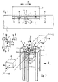
- ein Anwendungsbeispiel der erfindungsgemäßen Positionsbestimmungseinrichtung in schematischer Darstellung,
- Fig. 2
- eine Positionsbestimmungseinrichtung bevorzugten Aufbaus, wie sie beispielsweise in dem Anwendungsfall gemäß Fig. 1 zum Einsatz kommt, ohne Darstellung der zugeordneten beweglichen Körper,
- Fig. 3
- eine Seitenansicht der Anordnung aus Fig. 1 mit Blickrichtung gemäß Pfeil III in schematischer Darstellung,
- Fig. 4
- eine Prinzipskizze des Sensoraufbaus mit angeschlossener Auswerteeinrichtung,
- Fig. 5, 6 und 7
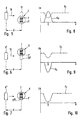
- die Positionsbestimmungseinrichtung unter Verwendung verschiedener Indikatortypen in Draufsicht gemäß Pfeil V aus Fig. 2,
- Fig. 8, 9 und 10
- die sich bei den Einsatzfällen der Fig. 5 bis 7 ergebenden Auswertediagramme,
- Fig. 11
- die Prinzipskizze eines Sensoraufbaus mit angeschlossener Auswerteeinrichtung zur Ermittlung der Auswertediagramme gemäß Fig. 8 bis 10 bei Verwendung von drei Indikatortypen und
- Fig. 12
- eine zweckmäßige Bauform eines Indikators.
- Fig. 1
- 1 shows an application example of the position determination device according to the invention in a schematic illustration,
- Fig. 2
- a position determining device of preferred construction, as used for example in the application according to FIG. 1, without showing the assigned movable bodies,
- Fig. 3
- 2 shows a side view of the arrangement from FIG. 1 with a viewing direction according to arrow III in a schematic illustration,
- Fig. 4
- a schematic diagram of the sensor structure with connected evaluation device,
- 5, 6 and 7
- the position determination device using different indicator types in plan view according to arrow V from FIG. 2,
- 8, 9 and 10
- 5 to 7 resultant evaluation diagrams,
- Fig. 11
- the basic sketch of a sensor structure with connected evaluation device for determining the evaluation diagrams according to FIGS. 8 to 10 when using three indicator types and
- Fig. 12
- an appropriate design of an indicator.
Aus Fig. 1 geht ein feststehender erster Körper 1 hervor,
an dem ein schlittenartiger zweiter Körper 2 in einer
durch Doppelpfeil 3 verdeutlichten Verlagerungsrichtung
hin und her bewegbar geführt angeordnet ist. Die Bewegung
des zweiten Körpers 2 wird durch eine nicht näher gezeigte
Antriebseinrichtung hervorgerufen. An den beiden Körpern
1, 2 ist eine Positionsbestimmungseinrichtung 4 angeordnet,
deren Aufbau im einzelnen aus Fig. 2 hervorgeht. Sie
ermöglicht die Erfassung bestimmter Relativpositionen
zwischen den beiden Körpern 1, 2.1 shows a fixed first body 1,
on which a sled-like
Die Positionsbestimmungseinrichtung 4 umfaßt einen Sensor
5, der über einen Halter 9 an dem ersten Körper 1 befestigt
ist. Ferner umfaßt die Positionsbestimmungseinrichtung 4
mehrere Indikatoren 6, 6', die mit dem Sensor 5 zusammenwirken
und an dem zweiten Körper 2 angeordnet sind. Die
Anordnung ist so getroffen, daß die Indikatoren 6, 6' bei
der Verlagerung des zweiten Körpers 2 den Sensor 5 in
unmittelbarer Nachbarschaft passieren.The position determining device 4 comprises a
Der beispielsgemäße Sensor 5 verfügt über zwei magnetfeldempfindliche
Sensoreinheiten 7, 7'. Es handelt sich hier
vorzugsweise um Halbleiter-Sensoreinheiten, die beim Ausführungsbeispiel
von sogenannten Feldplatten gebildet
sind. Alternativ könnte es sich auch um sogenannte Hall-Generatoren
handeln. Denkbar wäre auch die Verwendung
magnetores istiver Elemente. Der Aufbau und die Wirkungsweise
magnetfeldempfindlicher Sensoreinheiten ist z. B. in
dem Artikel "Magnetfeldempfindliche Halbleiter-Positionssensoren",
Sonderdruck aus "elektronik industrie", Heft 5/85
und 6/85, Seiten 1 bis 6, oder in dem Buch "Sensoren
Magnetfeldhalbleiter Teil 1", Datenbuch 1982/83, SIEMENS,
Seiten 40 bis 44, erläutert, so daß sich an dieser Stelle
nähere Ausführungen erübrigen.The
Die beiden Sensoreinheiten 7, 7' liegen zweckmäßigerweise
in einer gemeinsamen Ebene und sind nebeneinander angeordnet.
Diese Richtung der Nebeneinander-Anordnung sei als
Basisrichtung 8 bezeichnet, deren Verlauf in Fig. 1 und 2
durch eine strichpunktierte Linie angedeutet ist.The two
Der Sensor 5 und die Indikatoren 6, 6' sind mit Bezug zueinander
derart angeordnet, daß die Indikatoren 6, 6' beim
Bewegen des zweiten Körpers 2 an den beiden Sensoreinheiten
7, 7' berührungslos vorbeilaufen. Der Sensor 5 ist so
positioniert, daß die Sensoreinheiten 7, 7' dem in Fig. 1
und 2 durch eine strichpunktierte Linie angedeuteten Verlagerungsweg
12, 12' der Indikatoren 6, 6' zugewandt sind.
Im Betrieb laufen die Indikatoren 6, 6' somit mit Abstand
vor der Vorderseite 13 des Sensors 5 vorbei, in deren
Bereich sich die Sensoreinheiten 7, 7' befinden.The
Der Aufbau des beispielsgemäßen Sensors 5 kann dem auf
Seite 44 der erwähnten Veröffentlichung "Sensoren Magnetfeldhalbleiter
Teil 1" entsprechen. Demnach handelt es
sich bei den Sensoreinheiten 7, 7' um plattenförmige Elemente,
deren Plattenebenen parallel zueinander verlaufen
und vorzugsweise in einer gemeinsamen Ebene liegen. Der
Verlagerungsweg 12, 12' erstreckt sich parallel zu dieser
Ebene. Die beim Ausführungsbeispiel als Feldplatten ausgebildeten
Sensoreinheiten 7, 7' sind jeweils auf eine
isolierte Fläche eines aus Eisen bestehenden Polschuhs 14
aufgeklebt. Auf den dem Verlagerungsweg 12, 12' zugewandten
Plattenflächen der aus Halbleitermaterial bestehenden
Sensoreinheiten 7, 7' können Heicheisen-Polbleche aufgeklebt
sein (nicht dargestellt), die die beiden Feldplattensysteme
7, 7' vor mechanischer Beschädigung schützen.
Ferner kann eine jeweilige Sensoreinheit 7, 7' mit dem
zugeordneten Polschuh 14 in eine magnetfelddurchlässige
Umhüllung 15 eingebettet sein. Des weiteren sind diese
Teile beim Ausführungsbeispiel auf einem Dauermagnetstück
16 mit zweckmäßigerweise rechtwinkelig zur Plattenebene
ausgerichteter Polarisierung angebracht. Dieser Permanentmagnet
verursacht ein in Fig. 2 strichpunktiert angedeutetes
Magnetfeld 17, das die beiden Sensoreinheiten 7,
7' insbesondere im rechten Winkel zu ihren Plattenflächen
durchsetzt. Dieses Magnetfeld 17 strahlt über die Vorderseite
13 des Sensors 5 hinaus.The structure of the
Der Abstand des Sensors 5 von dem Verlagerungsweg 12, 12' ist
derart gewählt, daß die Indikatoren 6, 6' beim Bewegen des
zweiten Körpers 2 durch das Magnetfeld 17 hindurchlaufen.
Die Bewegungsrichtungen der Indikatoren 6, 6', die als
Arbeitsrichtungen 18 bezeichnet werden, sind in mehreren
der Figuren durch Pfeile bzw. Doppelpfeile kenntlich
gemacht. Sie verlaufen parallel zu der Verlagerungsrichtung
3. The distance of the
Die Indikatoren 6, 6' bestehen beim Ausführungsbeispiel
aus einem ferromagnetischen Material und dabei vorzugsweise
aus einfachem Stahl. Beim Durchlaufen des Magnetfeldes
17 verursachen sie eine Änderung desselben, woraus
eine Widerstandsänderung der als Feldplatten ausgebildeten
Sensoreinheiten 7, 7' resultiert. Aus dieser werden in
einer noch zu beschreibenden Auswerteeinrichtung 22
Steuersignale S1, S2 abgeleitet (Fig. 4), die beliebig
weiterverwertbar sind. Beispielsweise läßt sich damit die
auf den zweiten Körper 2 einwirkende Antriebseinrichtung
ansteuern, um somit in Abhängigkeit von bestimmten Positionen
des zweiten Körpers 2 dessen Bewegungsabläufe zu
steuern.The
Ein besonderer Vorteil der Positionsbestimmungseinrichtung
4 resultiert daraus, daß der Sensor 5 mit Bezug zu den
Indikatoren 6, 6' derart ausgerichtet ist, daß die Arbeitsrichtung
18 der Indikatoren 6, 6' quer zu der Basisrichtung
8 verläuft. Beispielsgemäß sind die beiden
Richtungen 18, 8 rechtwinkelig zueinander angeordnet, das
heißt, die Arbeitsrichtung 18 ist bezüglich der Basisrichtung
8 um 90° gedreht. Dies eröffnet äußerst flexible
Positionserfassungmöglichkeiten, wobei jedem Steuersignal
S1, S2 ein bestimmter Indikator und somit eine bestimmte
Position des zweiten Körpers 2 relativ zu dem
ersten Körper 1 zugeordnet werden kann.A particular advantage of the position determination device 4 results from the fact that the
Eine vorteilhafte Betriebsweise besteht darin, die beiden
Sensoreinheiten 7, 7' in einer sogenannten Differentialschaltung
zusammenzuschalten, so daß der Sensor 5 einen
Differentialsensor bildet. In dem Schaltschema der Fig. 4
sind die beiden Sensoreinheiten 7, 7' durch ihren über die
Indikatoren 6, 6' beeinflußbaren Feldplattenwiderstand 23,
23' abgebildet. Sie sind in eine Brückenschaltung 24 integriert,
wobei sie vorliegend die beiden in Reihe geschalteten
Brückenglieder des ersten Brücken-Längszweiges
25 bilden. Der parallelgeschaltete zweite Brücken-Längszweig
26 enthält als Brückenglieder zwei in Reihe geschaltete
Festwiderstände 27. Die am Brücken-Querzweig 28
abgreifbare Spannung bildet ein Ausgangssignal Ua, das bei
der Erzeugung der Steuersignale S1, S2 verwendet wird.An advantageous mode of operation is to interconnect the two
Bei dem Ausführungsbeispiel gemäß Fig. 1 bis 3 sind die
beiden Indikatoren 6, 6' nun derart angeordnet, daß sie
beim Vorbeilaufen an dem Sensor 5 jeweils nur das durch
eine Sensoreinheit 7, 7' hindurchgehende Magnetfeld beeinflussen.
Der eine Indikator 6 wirkt somit nur auf die
erste Sensoreinheit 7, während der andere Indikator 6'
ausschließlich auf die zweite Sensoreinheit 7' einwirkt.
Dadurch ändert sich im einen Falle nur der erste Festplattenwiderstand
23 und im anderen Falle nur der zweite
Festplattenwiderstand 23'. Infolge der Differentialschaltung
ergibt sich somit als Ausgangssignal Ua einmal
eine positive und das andere Mal eine negative Spannung.
Abgesehen von der eigentlichen Sensorbetätigung läßt sich
daraus vorteilhafterweise zweifelsfrei auch derjenige
Indikator mit Bestimmtheit ersehen, der die Sensorbetätigung
ausgelöst hat. Zweckmäßigerweise wird das Ausgangssignal
Ua zwei Komparatoren 31, 31' mit unterschiedlicher
Schwellenspannung zugeführt, so daß in Abhängigkeit von
dem erregenden Indikator 6, 6' ein Steuersignal S1 oder S2
entsteht.In the exemplary embodiment according to FIGS. 1 to 3, the two
Ersichtlich läßt sich also durch den voreingestellten
überdeckungsgrad, das heißt den Grad der Überdeckung der
beiden Sensoreinheiten 7, 7' durch einen sie passierenden
Indikator 6, 6', ein für einen jeweiligen überdeckungsgrad
charakteristisches Signal erzeugen, so daß man mit nur
einem Sensor und mehreren, in verschiedenen Positionen
angeordneten Indikatoren vielfältige und flexible
Positionsbestimmungsmöglichkeiten hat.So it can be seen through the preset
Degree of coverage, that is the degree of coverage of the
two
Beim Ausführungsbeispiel werden die Sensoreinheiten 7, 7'
beim Vorbeilaufen der Indikatoren 6, 6' von diesen zeitweilig
zu einem bestimmten Grad körperlich abgedeckt.
Unter dem Begriff "Überdeckung" werden vorliegend alle
Zustände verstanden, bei denen ein am Sensor 5 vorbeilaufender
Indikator 6, 6' das Magnetfeld 17 in relevantem
Maße beeinflußt, wobei ein jeweiliger Indikator 6, 6'
durchaus auch seitlich neben den Sensoreinheiten 7, 7'
vorbeilaufen kann.In the exemplary embodiment, the
Um unterschiedliche Oberdeckungsgrade zu erzielen, werden
die Indikatoren 6, 6' in entsprechenden Schaltpositionen
am zweiten Körper 2 angeordnet. Man erkennt aus Fig. 1,
daß die Indikatoren 6, 6' derart am zweiten Körper 2 angeordnet
sind, daß ihre Verlagerungswege 12, 12' parallel
und im Abstand nebeneinander verlaufen und dabei jeweils
rechtwinkelig zu der Basisrichtung 8 ausgerichtet sind.
Ein jeweiliger Verlagerungsweg 12, 12' läuft hier unmittelbar
vor einer jeweiligen Sensoreinheit 7, 7' vorbei.To achieve different degrees of coverage,
the
Zur besseren Unterscheidung seien vorliegend die einen unterschiedlichen Überdeckungsgrad aufweisenden Indikatoren als "Indikatortypen" bezeichnet. Beim Ausführungsbeispiel gemäß Fig. 1 bis 3 sind somit zwei Indikatortypen vorhanden. Prinzipiell wäre es natürlich möglich, mehrere Indikatoren vom gleichen Indikatortyp vorzusehen und diese entlang eines Verlagerungsweges mit Abstand zueinander anzuordnen. For better distinction, there are some indicators with different degrees of coverage referred to as "indicator types". In the embodiment 1 to 3 are thus two types of indicators available. In principle it would of course be possible to have several To provide indicators of the same indicator type and these along a displacement path at a distance from each other to arrange.
Vorzugsweise sind die Indikatoren 6, 6' in der zugeordneten
Arbeitsrichtung 18 bezüglich des sie tragenden
zweiten Körpers 2 verstellbar. Dies erlaubt eine variable
Vorgabe der gewünschten Schaltzeit. Gemäß Fig. 1 sind an
dem zweiten Körper 2 zwei parallel und mit Abstand zueinander
und in Verlagerungsrichtung 3 verlaufende Befestigungsnuten
oder -rippen 32 vorgesehen, an denen jeweils
mindestens ein Indikator 6, 6' derart gelagert ist, daß er
sich in Längsrichtung verstellen und in jeder gewünschten
Position unbewegbar festlegen läßt.The
Es versteht sich, daß die Befestigungsnuten bzw. -rippen
32 auch einen gebogenen Verlauf haben können, dies insbesondere
bei der Detektion zweier relativ zueinander eine
Schwenk- oder Drehbewegung ausführender Körper.It is understood that the fastening grooves or
Der Sensor 5 ist beim Ausführungsbeispiel unbewegbar an
dem ersten Körper angeordnet. Allerdings besteht auch hier
die Möglichkeit, eine verstellbare Montage vorzusehen.The
Während beim Ausführungsbeispiel gemäß Fig. 1 bis 3 der
Sensor 5 am feststehenden Körper und die Indikatoren am
sich bewegenden Körper angeordnet sind, kann diese Anordnung
bei Bedarf auch umgekehrt erfolgen. While in the embodiment of FIGS. 1 to 3 of
Die Fig. 5 bis 11 zeigen eine Anordnung, bei der ein Sensor
5 mit drei Indikatoren 6, 6', 6'' unterschiedlichen
Indikatortyps zusammenarbeitet. Diese drei Indikatoren 6,
6', 6'' überdecken die Sensoreinheiten 7, 7' beim Vorbeilaufen
am Sensor 5 in unterschiedlichem Maße. Die strichpunktiert
angedeuteten Stellungen 33, 33', 33'' in Fig. 5,
6 und 7 zeigen einen jeweiligen Indikator 6, 6', 6'' in
der dem Sensor 5 jeweils momentan gegenüberliegenden
Position, die als Betätigungsposition bezeichnet sei. Mit
"d" ist der Abstand zwischen einem sich an den Sensor 5
annähernden Indikator 6, 6', 6'' und seiner Betätigungsposition
33, 33', 33'' bezeichnet.5 to 11 show an arrangement in which a
Die Fig. 11 zeigt wiederum den mit einer Auswerteeinrichtung
22 verknüpften Sensor 5. Abgesehen von einem Vorwiderstand
44, der in Reihe mit der Brückenschaltung 24
liegt, entspricht der Aufbau der in Fig. 4 gezeigten
Auswerteschaltung. Zusätzlich zu dem Ausgangssignal Ua
wird hier der Spannungsabfall UV an dem Vorwiderstand 34
erfaßt und geht in die Ermittlung des betreffenden Steuersignals
mit ein.FIG. 11 in turn shows the
Der erste Indikator 6 gemäß Fig. 5 ist derart angeordnet,
daß er in der Betätigungsposition 33 die erste Sensoreinheit 7
insbesondere vollständig abdeckt. Die zweite Sensoreinrichtung
7' bleibt unabgedeckt. Auf Grund der Differentialschaltung
ergibt sich für das Ausgangssignal Ua die in
dem Diagramm der Fig. 8 dargestellte Kurve mit einem positiven
Spannungsausschlag beim Durchlaufen der Betätigungsposition
33.The
Der zweite Indikator 6' ist derart angeordnet, daß er in
der Betätigungsposition 33' nur die zweite Sensoreinheit 7'
insbesondere vollständig abdeckt, während hier die erste
Sensoreinheit 7 unbeeinflußt bleibt. Als Resultat ergibt
sich für das Ausgangssignal Ua die in Fig. 9 in durchgezogenen
Linien gezeigte Kurve mit einem negativen Spannungsausschlag
beim Durchlaufen der Schaltposition.The second indicator 6 'is arranged in such a way that in the actuating position 33' it covers only the second sensor unit 7 ', in particular completely, while the
Vergleichbar der in Fig. 4 beschriebenen Art und Weise lassen sich die Ausgangssignale Ua in der Auswerteeinrichtung auswerten. Es genügen hier beispielsweise zwei Komparatoren mit zum einen einer positiven und zum anderen einer negativen Schwellenspannung.Comparable to the manner described in FIG. 4, the output signals U a can be evaluated in the evaluation device. For example, two comparators with a positive and a negative threshold voltage are sufficient here.
In den Diagrammen gemäß Fig. 8 und 9 ist gestrichelt auch
der Spannungsabfall UV aufgetragen, der für die Ermittlung
der ersten und zweiten Betätigungsposition 33, 33' jedoch nicht
notwendigerweise zu verwerten ist. Er wird beispielsgemäß
zur Detektion der dritten Betätigungsposition 33'' verwendet,
die dadurch gekennzeichnet ist, daß der zweite Indikator
6'' beide Sensoreinheiten 7, 7' gleichzeitig vorzugsweise
vollständig abdeckt. Bei idealer exakter Ausrichtung der
Sensoreinheiten 7, 7' wird sich hier auf Grund des Differentialprinzips
kaum ein Spannungsausschlag als Ausgangssignal
Ua ergeben. Da beide Sensoreinheiten 7, 7' abgedeckt
sind, vergrößert sich jedoch der Widerstand in dem
die Sensoreinheiten 7, 7' enthaltenden ersten Brücken-Längszweig
25, so daß der Spannungsabfall UV an dem Vorwiderstand
34 im Vergleich zu den Betätigungspositionen 33, 33'
geringer ist. Dies ist in der Verlaufskurve des Spannungsabfalls
UV der Fig. 10 wiedergegeben. Mittels eines geeigneten
Komparators läßt sich hiermit auch die dritte
Betätigungsposition 33'' zuordnungsrichtig detektieren.The voltage drop U V is also shown in dashed lines in the diagrams according to FIGS. 8 and 9, but this drop is not necessarily to be used for determining the first and second actuation positions 33, 33 '. It is used, for example, to detect the
Ersichtlich lassen sich in die Positionsbestimmungseinrichtung
bei Bedarf noch weitere Indikatortypen integrieren,
die sich von den bisher geschilderten durch den Grad
der Überdeckung der Sensoreinheiten 7, 7' in der Betätigungsposition
unterscheiden.Can be seen in the position determining device
integrate further indicator types if necessary,
which differ from those previously described by the degree
the coverage of the
Anstelle lediglich zweier Sensoreinheiten 7, 7' wäre es
auch denkbar, den Sensor 5 mit mehr als zwei Sensoreinheiten
zu bestücken. Instead of just two
Die Anordnung und Auswertung der Positionsbestimmungseinrichtung
bei mit Hall-Generatoren oder magnetoresistiven
Elementen ausgestatteten Sensoren ist mit der geschilderten
vergleichbar. Hier empfiehlt es sich allerdings, einen
jeweiligen Indikator als Permanentmagnet auszubilden,
dessen Magnetfeld beim Vorbeistreichen am Sensor 5 auf die
Sensoreinheiten einwirkt, so daß diese einem sich ändernden
Einfluß eines Magnetfelds ausgesetzt sind.The arrangement and evaluation of the position determining device
with with Hall generators or magnetoresistive
Elements equipped sensors is with the described
comparable. Here, however, it is recommended to use one
to design each indicator as a permanent magnet,
whose magnetic field when passing the
Bei entsprechend unterschiedlicher Ausgestaltung der
Indikatoren unterschiedlichen Indikatortyps wäre es ohne
weiteres möglich, nur eine einzige Befestigungsnut oder
-rippe 32 vorzusehen, auf denen alle Indikatoren angeordnet
sind. Zugunsten einer einheitlichen und rationellen
Fertigung ist allerdings eine einheitliche äußere geometrische
Gestaltung auch unterschiedlicher Indikatortypen
anzustreben. Hierzu empfiehlt es sich, die Indikatoren als
bestimmten Bestandteil eines einheitliche Außenabmessungen
aufweisenden Basiskörpers 35 vorzusehen, wie es in Fig. 12
angedeutet ist. Der Basiskörper 35 setzt sich hier aus
zwei nebeneinanderliegenden Abschnitten 36, 37 zusammen,
von denen der eine Abschnitt 37 den Indikator 6 bildet.
Dieser Basiskörper 35 kann in der in Fig. 7 erläuterten
Art und Weise über einen Sensor 5 hinwegbewegt werden, so
daß beide Sensoreinheiten 7, 7' gleichzeitig überdeckt
werden. Die erzielte Wirkung ist allerdings diejenige der
Fig. 6, da nur der als Indikator wirkende Abschnitt 37
eine Einflußnahme auf das Magnetfeld vornimmt. Eine derartige
Einflußnahme wird durch den verbleibenden Abschnitt
36 nicht oder nur in geringem Maße ausgeübt, da er aus
einem ein Magnetfeld nicht oder nur unwesentlich beeinflussenden
Material besteht. Denkbar wäre es natürlich
auch, den Basiskörper in mehrere Materialabschnitte mit
unterschiedlicher Permeabilität zu unterteilen, wobei dann
von Fall zu Fall festgelegt werden kann, welcher Abschnitt
als Indikator herangezogen werden soll. So könnte ein
Basiskörper beispielsweise in zwei Hälften unterteilt
sein, wovon die eine austenitische und die andere ferritische
Eigenschaften aufweist. Eine derartige Unterteilung
ist in Fig. 1 strichpunktiert bei 38 angedeutet.With a correspondingly different design of the
It would be without indicators of different indicator types
further possible, only a single fastening groove or
Der Basiskörper 35 kann ein mehrteiliger Körper sein,
wobei die einzelnen Körperabschnitte aus separaten Materialteilen
bestehen, die zusammengesetzt wurden, um den
Basiskörper 35 zu bilden.The
Lediglich durch eine um 180° geänderte Einbaulage läßt
sich mit einem derartigen Basiskörper 35 wahlweise ein
erster Indikator 6 oder ein zweiter Indikator 6' gemäß den
Fig. 5 und 6 verwirklichen. Only by changing the installation position by 180 °
yourself with such a
Werden mehrere Indikatoren eines bestimmten Indikatortyps
in Arbeitsrichtung 18 hintereinander in verschiedenen
Abständen montiert und ein Indikator eines weiteren Indikatortyps
als Referenzmarke genommen, kann mit einer
entsprechenden Anordnung eine Ablaufsteuerung erstellt
werden, wobei jeder Indikator für das Auslösen einer
bestimmten Funktion steht. Indikatoren gleichen Typs
können hier durch einen überlagerten Zählvorgang voneinander
unterscheidbar gemacht werden.There are several indicators of a certain indicator type
in the working
Um eine Ablaufsteuerung zu verwirklichen, die eine Erkennung der Bewegungsrichtung ermöglicht, also eine sogenannte Vorwärts-Rückwärts-Erkennung, sollten wenigstens drei Indikatortypen vorhanden sein. Werden diese in einer Typenreihenfolge 1 - 2 - 3 - 1 - 2 - 3 - 1 ... angeordnet, so kann über die Bewegungsrichtung des Sensors bzw. der Indikatoren auf Grund der immer unterschiedlichen benachbarten Indikatoren eine eindeutige Aussage gemacht werden.To implement a sequential control system, the one Detection of the direction of movement enables, i.e. a so-called forward-backward detection, should there must be at least three types of indicators. Become these in a type order 1 - 2 - 3 - 1 - 2 - 3 - 1 ... arranged, can about the direction of movement of the sensor or the indicators due to the always different neighboring indicators made a clear statement become.
Ein jeweiliger Indikator kann ein am zugeordneten Körper angebrachtes Zusatzteil sein, beispielsweise ein nockenoder klotzartiges Teil, wie in Fig. 1 und 2 gezeigt. Darüber hinaus könnten die Indikatoren auch unmittelbar von einem Bestandteil des in seiner Bewegung zu steuernden Körpers gebildet sein, beispielsweise die Zähne eines Zahnrades.A respective indicator can be on the assigned body attached additional part, for example a cam or block-like part as shown in Figs. 1 and 2. About that In addition, the indicators could also be directly from a component of the movement to be controlled Be formed body, for example the teeth of a gear.
Besonders vorteilhaft läßt sich die Positionsbestimmungseinrichtung
im Zusammenhang mit Linear-, Schwenk- und
Drehantrieben einsetzen. Der die Arbeitsrichtungen 18
bestimmende Verlagerungsweg 12, 12' muß daher nicht notwendigerweise
linear sein, sondern kann insbesondere auch
eine Kreisbogenform haben. Man könnte an einem im Betrieb
sich drehenden Teil in Umfangsrichtung versetzt mehrere
Indikatoren anbringen, die bei der Rotationsbewegung an
einem Sensor vorbeilaufen, der am feststehenden Teil
angebracht ist.The position determining device can be particularly advantageous
related to linear, swivel and
Use multi-turn actuators. The 18
determining
Die erfindungsgemäße Positionsbestimmungseinrichtung läßt sich äußerst flexibel einsetzen und ermöglicht die relativ einfache Lösung auch komplexer Automatisierungsprobleme.The position determining device according to the invention can deploy yourself extremely flexibly and enables that relatively simple solution to complex automation problems.
Claims (18)
- Device for determining the relative position between two bodies (1, 2) movable relative to one another, with a sensor (5) provided on the first body (1) with at least two magnetic-field-sensitive sensor units (7, 7'), arranged next to one another in a base direction (8) and with several indicators (6, 6' 6") provided on the second body (2) in such a way that, during a relative movement of the two bodies (1, 2), the sensor (5) and the indicators (6, 6' 6") may be moved past one another in an operating direction (18) at right-angles to the base direction, wherein the sensor (5) during the passing movement of each of the indicators (6, 6' 6") is under the changing influence of a magnetic field (17), and the indicators (6, 6' 6") spaced apart in different switching positions along the operating direction (18) brush past the sensor units (7, 7') with varying coverage, wherein after one of the indicators (6, 6' 6") has brushed past the sensor units (7, 7') until the the next indicator brushes past there is a further switching condition in which none of the indicators covers the sensor units (7, 7').
- Device according to claim 1, characterised in that the sensor units (7, 7') have a semiconductor structure.
- Device according to claim 1 or 2, characterised in that the sensor units (7,7') are formed by Hall generators.
- Device according to claim 1 or 2, characterised in that the sensor units (7, 7') are formed by magneto resistors.
- Device according to claim 1 or 2, characterised in that the sensor units (7, 7') are formed by magneto-resistive elements.
- Device according to any of claims 1 to 5, characterised in that the indicators (6, 6' 6"), in the case of plate-shaped sensor units (7, 7'), are moved past opposite the plate surfaces.
- Device according to any of claims 1 to 6, characterised in that the operating direction (18) and the base direction (8) run at right-angles to one another.
- Device according to any of claims 1 to 7, characterised in that the sensor units (7, 7') are arranged in a common plane running parallel to the operating direction (18).
- Device according to any of claims 1 to 8, characterised in that the sensor (5) is designed as a differential sensor.
- Device according to any of the preceding claims, characterised in that there is at least one first indicator (6) which, on moving past the sensor (5), covers only a first (7) of the available sensor units at least partially, and that there is at least one further indicator (6') which, on moving past the sensor (5), covers only another second sensor unit (7') or the two sensor units (7, 7') simultaneously at least partially.
- Device according to any of the preceding claims, characterised in that the sensor (5) and/or the one or more indicators (6, 6' 6") are arranged on the assigned body (1,2) so as to be adjustable in the operating direction (18).
- Device according to any of the preceding claims, characterised in that the indicator (6,6' 6") is a permanent magnet providing the magnetic field (17) which influences the sensor (5).
- Device according to any of the preceding claims, characterised in that the indicator (6, 6' 6") is a ferro-magnetic part, wherein the magnetic field (17) influencing the sensor (5) is supplied by a magnet (16) provided on the sensor (5).
- Device according to any of the preceding claims, characterised by an analyser unit (22) which, depending on an output signal (Ua) which in turn is dependent on the degree of coverage of the available sensor units (7, 7), supplies a specific control signal (S1, S2).
- Device according to claim 14, characterised in that the sensor units (7, 7') are inserted in the longitudinal branch (25) of a bridge connection (24), with the respective voltage applied at the cross branch (28) of the bridge connection (24) supplying the output signal (Ua).
- Device according to claim 15, characterised in that a series resistor (34), the voltage drop (Uv) of which processes one or more of the control signals during determination, is inserted before the bridge connection (24).
- Device according to claim 15 or 16, characterised in that a positive and a negative voltage output signal (Ua) indicate the at least partial coverage of only one sensor unit (7, 7'), while the at least partial coverage of several sensor units (7, 7') is determined with allowance for the changed voltage drop (Uv) of the series resistor (34).
- Device according to any of the preceding claims, characterised in that each indicator (6, 6' 6") is formed by a predetermined section (37) of a base body (35) and is distinguished by a material property differing in comparison with the remaining section (36) of the base body (35).
Applications Claiming Priority (2)
| Application Number | Priority Date | Filing Date | Title |
|---|---|---|---|
| DE4432827 | 1994-09-15 | ||
| DE4432827A DE4432827C2 (en) | 1994-09-15 | 1994-09-15 | Positioning device |
Publications (3)
| Publication Number | Publication Date |
|---|---|
| EP0702203A2 EP0702203A2 (en) | 1996-03-20 |
| EP0702203A3 EP0702203A3 (en) | 1998-11-04 |
| EP0702203B1 true EP0702203B1 (en) | 2003-11-12 |
Family
ID=6528265
Family Applications (1)
| Application Number | Title | Priority Date | Filing Date |
|---|---|---|---|
| EP95111286A Expired - Lifetime EP0702203B1 (en) | 1994-09-15 | 1995-07-19 | Position recording with two magnetic field sensors arranged side by side |
Country Status (2)
| Country | Link |
|---|---|
| EP (1) | EP0702203B1 (en) |
| DE (2) | DE4432827C2 (en) |
Families Citing this family (4)
| Publication number | Priority date | Publication date | Assignee | Title |
|---|---|---|---|---|
| DE19803018C2 (en) * | 1997-03-05 | 2000-09-07 | Vs Sensorik Gmbh | Magnetic sensor |
| DE19757116C2 (en) * | 1997-12-20 | 2001-02-22 | Daimler Chrysler Ag | Magnetic scale arrangement |
| JP3532778B2 (en) * | 1998-05-15 | 2004-05-31 | 株式会社東海理化電機製作所 | Rotation detection sensor |
| DE10024850C2 (en) * | 2000-05-19 | 2003-01-23 | Deutsch Zentr Luft & Raumfahrt | Measuring arrangement, measuring head and method for producing a measuring head |
Family Cites Families (11)
| Publication number | Priority date | Publication date | Assignee | Title |
|---|---|---|---|---|
| US4616281A (en) * | 1982-03-10 | 1986-10-07 | Copal Company Limited | Displacement detecting apparatus comprising magnetoresistive elements |
| DE3214794C2 (en) * | 1982-04-21 | 1984-06-07 | Dr. Johannes Heidenhain Gmbh, 8225 Traunreut | Magnetic length or angle measuring device |
| DE3245357C2 (en) * | 1982-12-08 | 1985-02-14 | Dr. Johannes Heidenhain Gmbh, 8225 Traunreut | Incremental measuring device |
| DE3447325A1 (en) * | 1984-12-24 | 1986-06-26 | Standard Elektrik Lorenz Ag | POSITION SENSOR |
| DE9010114U1 (en) * | 1990-07-03 | 1990-09-06 | Festo Kg, 7300 Esslingen, De | |
| DE4037545C2 (en) * | 1990-11-26 | 1994-03-17 | Heidenhain Gmbh Dr Johannes | Measuring device |
| DE4038674A1 (en) * | 1990-12-04 | 1992-06-11 | Automata Gmbh Ind & Robotic Co | DEVICE FOR DETERMINING THE ABSOLUTE ACTUAL POSITION OF AN ALONG A PRE-DETERMINED ROUTE OF MOVABLE COMPONENTS |
| FR2670888B1 (en) * | 1990-12-19 | 1994-05-27 | Aerospatiale | ANGULAR POSITION SENSOR WITH MAGNETORESISTANCES. |
| EP0496918A1 (en) * | 1991-01-31 | 1992-08-05 | Siemens Aktiengesellschaft | System for generating pulse signals from markings on a passing object |
| DE4129576C2 (en) * | 1991-09-06 | 2001-05-31 | Mueller Arnold Gmbh Co Kg | Magnetic measuring system for measuring the angle of rotation |
| EP0569613B1 (en) * | 1992-05-15 | 1996-04-10 | Siemens Aktiengesellschaft | Device for non-contact establishment of rotary position or speed |
-
1994
- 1994-09-15 DE DE4432827A patent/DE4432827C2/en not_active Expired - Fee Related
-
1995
- 1995-07-19 DE DE59510825T patent/DE59510825D1/en not_active Expired - Fee Related
- 1995-07-19 EP EP95111286A patent/EP0702203B1/en not_active Expired - Lifetime
Also Published As
| Publication number | Publication date |
|---|---|
| DE59510825D1 (en) | 2003-12-18 |
| EP0702203A3 (en) | 1998-11-04 |
| EP0702203A2 (en) | 1996-03-20 |
| DE4432827C2 (en) | 1998-10-22 |
| DE4432827A1 (en) | 1996-03-28 |
Similar Documents
| Publication | Publication Date | Title |
|---|---|---|
| DE2558956C2 (en) | ||
| EP1462661B1 (en) | Position determination device for fluid actuated piston-cylinder assemblies | |
| EP0646775B1 (en) | Apparatus for angular position determination | |
| DE10037211B4 (en) | Steering wheel position sensor | |
| DE4408623A1 (en) | Magnetic position sensor | |
| DE102010056271B4 (en) | Sensor arrangement for detecting both the axial and the rotational position of a longitudinally displaceable and rotatable shaft | |
| EP1770373A1 (en) | Absolute position measuring device | |
| EP2210018B1 (en) | Sensor for the shift position of a selector shaft and corresponding detection method | |
| EP1832851B1 (en) | Encoder for an actuator, linear induction motor and method for manufacturing a linear motor | |
| EP2846126B1 (en) | Measuring device and a method for measuring the position of bodies | |
| EP0702203B1 (en) | Position recording with two magnetic field sensors arranged side by side | |
| DE2329845C3 (en) | Measuring arrangement for converting mechanical displacements into proportional electrical quantities | |
| EP0775835A2 (en) | Position detection apparatus | |
| DE102005061347A1 (en) | Shaft`s absolute rotation angle measuring arrangement, has two diametrically magnetizable rings, and magnetic field sensors arranged adjacent to surrounding of rings, such that radial component of magnetic field of one ring is detected | |
| EP1321743B1 (en) | Absolute length measuring system with a measuring rod moving with respect to mutually spaced length sensors | |
| DE10153915B4 (en) | Method and device for setting the actual position of a wheel to be steered in a truck with an electric steering | |
| DE19800774A1 (en) | Reference signal generation for magneto-resistive sensor | |
| DE3123572C2 (en) | Measuring system for the contactless detection of piston rod positions | |
| DE4213507C2 (en) | Device for the contactless measurement of the axial position of a rotating body | |
| DE4210934C1 (en) | ||
| EP1742022A1 (en) | Position detection on a rod | |
| DE10329045B4 (en) | Means for determining at least one end position of a drive member, in particular a fluid-operated linear or rotary drive | |
| DE102013205216A1 (en) | Linear actuator with measuring device for measuring the position of a drive element | |
| DE3109911C1 (en) | Capacitive signal transmitter | |
| DE60034471T2 (en) | ELECTRONIC STEERING MODULE |
Legal Events
| Date | Code | Title | Description |
|---|---|---|---|
| PUAI | Public reference made under article 153(3) epc to a published international application that has entered the european phase |
Free format text: ORIGINAL CODE: 0009012 |
|
| AK | Designated contracting states |
Kind code of ref document: A2 Designated state(s): CH DE FR GB IT LI NL |
|
| RAP1 | Party data changed (applicant data changed or rights of an application transferred) |
Owner name: FESTO AG & CO |
|
| PUAL | Search report despatched |
Free format text: ORIGINAL CODE: 0009013 |
|
| AK | Designated contracting states |
Kind code of ref document: A3 Designated state(s): CH DE FR GB IT LI NL |
|
| 17P | Request for examination filed |
Effective date: 19981019 |
|
| 17Q | First examination report despatched |
Effective date: 20010913 |
|
| GRAH | Despatch of communication of intention to grant a patent |
Free format text: ORIGINAL CODE: EPIDOS IGRA |
|
| RTI1 | Title (correction) |
Free format text: POSITION RECORDING WITH TWO MAGNETIC FIELD SENSORS ARRANGED SIDE BY SIDE |
|
| RTI1 | Title (correction) |
Free format text: POSITION RECORDING WITH TWO MAGNETIC FIELD SENSORS ARRANGED SIDE BY SIDE |
|
| GRAS | Grant fee paid |
Free format text: ORIGINAL CODE: EPIDOSNIGR3 |
|
| GRAA | (expected) grant |
Free format text: ORIGINAL CODE: 0009210 |
|
| AK | Designated contracting states |
Kind code of ref document: B1 Designated state(s): CH DE FR GB IT LI NL |
|
| PG25 | Lapsed in a contracting state [announced via postgrant information from national office to epo] |
Ref country code: NL Free format text: LAPSE BECAUSE OF FAILURE TO SUBMIT A TRANSLATION OF THE DESCRIPTION OR TO PAY THE FEE WITHIN THE PRESCRIBED TIME-LIMIT Effective date: 20031112 Ref country code: IT Free format text: LAPSE BECAUSE OF FAILURE TO SUBMIT A TRANSLATION OF THE DESCRIPTION OR TO PAY THE FEE WITHIN THE PRESCRIBED TIME-LIMIT;WARNING: LAPSES OF ITALIAN PATENTS WITH EFFECTIVE DATE BEFORE 2007 MAY HAVE OCCURRED AT ANY TIME BEFORE 2007. THE CORRECT EFFECTIVE DATE MAY BE DIFFERENT FROM THE ONE RECORDED. Effective date: 20031112 Ref country code: GB Free format text: LAPSE BECAUSE OF FAILURE TO SUBMIT A TRANSLATION OF THE DESCRIPTION OR TO PAY THE FEE WITHIN THE PRESCRIBED TIME-LIMIT Effective date: 20031112 Ref country code: FR Free format text: LAPSE BECAUSE OF FAILURE TO SUBMIT A TRANSLATION OF THE DESCRIPTION OR TO PAY THE FEE WITHIN THE PRESCRIBED TIME-LIMIT Effective date: 20031112 |
|
| REG | Reference to a national code |
Ref country code: GB Ref legal event code: FG4D Free format text: NOT ENGLISH |
|
| REG | Reference to a national code |
Ref country code: CH Ref legal event code: EP |
|
| REF | Corresponds to: |
Ref document number: 59510825 Country of ref document: DE Date of ref document: 20031218 Kind code of ref document: P |
|
| NLV1 | Nl: lapsed or annulled due to failure to fulfill the requirements of art. 29p and 29m of the patents act | ||
| GBV | Gb: ep patent (uk) treated as always having been void in accordance with gb section 77(7)/1977 [no translation filed] |
Effective date: 20031112 |
|
| PGFP | Annual fee paid to national office [announced via postgrant information from national office to epo] |
Ref country code: DE Payment date: 20040717 Year of fee payment: 10 |
|
| PG25 | Lapsed in a contracting state [announced via postgrant information from national office to epo] |
Ref country code: LI Free format text: LAPSE BECAUSE OF NON-PAYMENT OF DUE FEES Effective date: 20040731 Ref country code: CH Free format text: LAPSE BECAUSE OF NON-PAYMENT OF DUE FEES Effective date: 20040731 |
|
| PLBE | No opposition filed within time limit |
Free format text: ORIGINAL CODE: 0009261 |
|
| STAA | Information on the status of an ep patent application or granted ep patent |
Free format text: STATUS: NO OPPOSITION FILED WITHIN TIME LIMIT |
|
| 26N | No opposition filed |
Effective date: 20040813 |
|
| EN | Fr: translation not filed | ||
| REG | Reference to a national code |
Ref country code: CH Ref legal event code: PL |
|
| PG25 | Lapsed in a contracting state [announced via postgrant information from national office to epo] |
Ref country code: DE Free format text: LAPSE BECAUSE OF NON-PAYMENT OF DUE FEES Effective date: 20060201 |