EP0701951B1 - Pump device for a container - Google Patents
Pump device for a container Download PDFInfo
- Publication number
- EP0701951B1 EP0701951B1 EP95915323A EP95915323A EP0701951B1 EP 0701951 B1 EP0701951 B1 EP 0701951B1 EP 95915323 A EP95915323 A EP 95915323A EP 95915323 A EP95915323 A EP 95915323A EP 0701951 B1 EP0701951 B1 EP 0701951B1
- Authority
- EP
- European Patent Office
- Prior art keywords
- holding rod
- pump device
- gap holding
- container
- contents
- Prior art date
- Legal status (The legal status is an assumption and is not a legal conclusion. Google has not performed a legal analysis and makes no representation as to the accuracy of the status listed.)
- Expired - Lifetime
Links
- 238000012856 packing Methods 0.000 claims description 17
- 230000002093 peripheral effect Effects 0.000 claims description 15
- 238000001125 extrusion Methods 0.000 claims description 9
- 239000000463 material Substances 0.000 claims description 4
- 230000003247 decreasing effect Effects 0.000 claims description 3
- 230000000717 retained effect Effects 0.000 claims description 2
- 239000007788 liquid Substances 0.000 description 12
- 238000000034 method Methods 0.000 description 9
- 238000000465 moulding Methods 0.000 description 4
- 238000010276 construction Methods 0.000 description 2
- 230000008602 contraction Effects 0.000 description 2
- 230000001747 exhibiting effect Effects 0.000 description 2
- 238000004519 manufacturing process Methods 0.000 description 2
- 230000003449 preventive effect Effects 0.000 description 2
- 230000008961 swelling Effects 0.000 description 2
- 230000000903 blocking effect Effects 0.000 description 1
- 238000001816 cooling Methods 0.000 description 1
- 238000005520 cutting process Methods 0.000 description 1
- 238000004299 exfoliation Methods 0.000 description 1
- 235000012438 extruded product Nutrition 0.000 description 1
- 238000005304 joining Methods 0.000 description 1
- 239000004033 plastic Substances 0.000 description 1
- 230000000630 rising effect Effects 0.000 description 1
- 239000007779 soft material Substances 0.000 description 1
- 239000012815 thermoplastic material Substances 0.000 description 1
- 238000011144 upstream manufacturing Methods 0.000 description 1
Images








Classifications
-
- B—PERFORMING OPERATIONS; TRANSPORTING
- B05—SPRAYING OR ATOMISING IN GENERAL; APPLYING FLUENT MATERIALS TO SURFACES, IN GENERAL
- B05B—SPRAYING APPARATUS; ATOMISING APPARATUS; NOZZLES
- B05B15/00—Details of spraying plant or spraying apparatus not otherwise provided for; Accessories
- B05B15/30—Dip tubes
-
- B—PERFORMING OPERATIONS; TRANSPORTING
- B05—SPRAYING OR ATOMISING IN GENERAL; APPLYING FLUENT MATERIALS TO SURFACES, IN GENERAL
- B05B—SPRAYING APPARATUS; ATOMISING APPARATUS; NOZZLES
- B05B11/00—Single-unit hand-held apparatus in which flow of contents is produced by the muscular force of the operator at the moment of use
- B05B11/01—Single-unit hand-held apparatus in which flow of contents is produced by the muscular force of the operator at the moment of use characterised by the means producing the flow
- B05B11/10—Pump arrangements for transferring the contents from the container to a pump chamber by a sucking effect and forcing the contents out through the dispensing nozzle
- B05B11/1001—Piston pumps
- B05B11/1023—Piston pumps having an outlet valve opened by deformation or displacement of the piston relative to its actuating stem
-
- B—PERFORMING OPERATIONS; TRANSPORTING
- B05—SPRAYING OR ATOMISING IN GENERAL; APPLYING FLUENT MATERIALS TO SURFACES, IN GENERAL
- B05B—SPRAYING APPARATUS; ATOMISING APPARATUS; NOZZLES
- B05B11/00—Single-unit hand-held apparatus in which flow of contents is produced by the muscular force of the operator at the moment of use
- B05B11/01—Single-unit hand-held apparatus in which flow of contents is produced by the muscular force of the operator at the moment of use characterised by the means producing the flow
- B05B11/02—Membranes or pistons acting on the contents inside the container, e.g. follower pistons
- B05B11/026—Membranes separating the content remaining in the container from the atmospheric air to compensate underpressure inside the container
Definitions
- the present invention relates generally to a pump device for a container and, more particularly, to a pump device for a container wherein the pump device is capable of delivering substantially the entire contents of the container.
- FIG. 30 illustrates a known container for pouring out contents having a high viscosity or contents altering in viscosity upon contact with the outside air.
- This container 1 includes a flexible content-filled sealed bag 2 housed in the interior thereof, and a pump 4 mounted in a mouth cylindrical portion 3.
- This pump 4 is equipped with an operating portion 5 exposed to the outside of the container 1 and a suction portion 6 inserted into the sealed bag 2.
- the suction portion 6 takes a pipe-like shape, is formed with a suction port 6a opened at a front edge thereof, and extends to an area in the vicinity of a bottom of the sealed bag 2.
- the contents 7 present in an upper area of the sealed bag 2 are hindered from flowing to the suction port 6a of the suction portion 6, and thus the contents 7 stay in the upper area due to a local shrinkage of the bottom of the sealed bag 2 in combination therewith. Thus, it is uneconomical that the contents 7 stay in the upper area of the sealed bag 2.
- JP-A-5-319467 seeks to alleviate the problem of the sealed bag coming into too close contact with the suction pipe by providing a cylindrical suction pipe with suction holes in a side wall thereof.
- An alternative solution is proposed in JP-A-5-319468 wherein a finned rod surmounted by a cylindrical member extends from the suction port.
- a pump device for a container used by attaching said pump device to a container having a contents filled sealed bag contracting with a negative pressurisation of an interior thereof when taking out the contents thereof, said pump device comprising:
- the piston is cylindrical and the piston packing is movably mounted to said piston.
- the pump device includes a valve which, in use, allows a portion of the contents of the container to enter the pump device.
- the valve may comprise a ball and a seat.
- the operating portion comprises a head member and a discharge port and the piston, piston packing and head member are biased upwardly by a spring provided within the pump device.
- the suction port is retained within a lower cylindrical portion of the suction portion by a circumferential protrusion provided upon an inner surface of said lower cylindrical portion.
- the gap holding rod may have a uniform cross-sectional dimension along its entire length and may be formed by extrusion.
- the gap holding rod may be formed by the removal of material from a cylindrical rod and may be cruciform, Y-shaped or sinuous in cross-section.
- the container may comprise a laminated container and, in use, an inner layer of said laminated container defines said contents filled sealed bag.
- the present invention adopts the following construction.
- a pump device for a container used by attaching the pump device to the container having a contents-filled sealed bag contracting with a negative pressurisation of an interior thereof when taking out the contents
- the pump device has an operating portion exposed to the outside of the container and a suction portion, inserted into the container, for sucking the contents out of a suction port.
- the pump device for the container further comprises a gap holding rod having its proximal end internally fitted into the suction port of the suction portion and its distal end extending toward an inner bottom portion of the contents-filled sealed bag. Protruded portions and recessed portions extending from the proximal end of the gap holding rod toward the distal end thereof are formed alternately in a circumferential direction on an outer peripheral surface of the gap holding rod.
- the gap holding rod is, it can be considered, in terms of a sectional configuration thereof, constructed such that at least all the outermost-positioned protruded portion outermost sides of each of the protruded portions take outwardly-convex circular arcs or straight lines.
- the interior of the container is depressurised as the contents are poured out.
- the contents-filled sealed bag is pulled in by the negative pressure with an exfoliation from an outer layer thereof, and consequently only an inner layer turns to be a bag and is then deformed by the contraction.
- the suction port is invariably kept clear. Even if the contents-filled sealed bag is closely fitted to the gap holding rod, the contents-filled sealed bag is not, though closely fitted to the protruded portion of the gap holding rod, closely fitted to the recessed portion. Hence, this recessed portion is secured as a passageway for the contents Accordingly, even when the contents are reduced, the contents can be surely sucked.
- the gap holding rod may also be, though internally fitted in the suction port and fixed thereto, mounted in the suction port through a mounting connection pipe.
- the contents-filled sealed bag used in the present invention is composed of a soft material exhibiting a flexibility. Therefore, the operation for securing the passageways for the contents depends on not only the material of the sealed hag and the viscosity of the contents but also the sectional configuration of the gap holding rod. The following are respective examinations which will be made.
- the passageways for the contents should be concentrated on the recessed portions as much as possible.
- the passage diverges, and as a result a perimeter of the section of the passageway is long for a sum of the sectional areas of the passageway secured (a surface area of an internal wall of the passageway increasing even at the same flow rate).
- a loss to friction increases correspondingly, resulting in a rise of so-called pump loss.
- the soft sealed bag each time it closely fits to the gap holding rod and separates therefrom, the soft sealed bag is repeatedly damaged by the edge of the protruded portion outermost side. It is therefor difficult to adopt the soft sealed bag. As in the case of the present invention, however, this can be prevented by using the protruded portion outermost side assuming the outwardly-convex protruded portion outermost side.
- the gap holding rod can be formed by a moulding method other than a contour extrusion moulding method using a dedicated die.
- the gap holding rod is formed by joining pre-cast tabular mouldings with their sides each defined as a straight line in terms of the sectional configuration thereof. According to this method, the gap holding rod can be designed without being machined by manufacturing equipment.
- the pump device according to the present invention is also established with an addition of constructive elements which will be given as follows.
- the gap holding rod formed by the contour extrusion moulding method.
- the gap holding rod can be formed by the contour extrusion moulding method, cut off to a predetermined length and then used. This leads to a remarkably high productivity, and a reduction in costs can be attained.
- the contour extrusion moulding method is a method of forming a special shape product by heat pressurising a thermoplastic material in an extruder and consecutively extruding it from the die, while the special shape product is an unshaped elongate extruded product that is not included in shaped products having sectional configurations such as a circle, a rectangle and a regular polygon.
- the gap holding rod is in an unstable state till it is extruded from the die by the contour extrusion moulding method and hardened by cooling but enhances in terms of its configurational retentivity thereof during that period by forming the above swelling.
- an outer peripheral surface of the suction portion is formed with grooves extending in such a direction as to get close to the suction port.
- the configuration of the groove is not particularly limited.
- a pump device 4 is fitted in a cylindrical mouth 3 of a container 1.
- a contents-filled sealed bag (hereinafter simply referred to as a sealed bag) exhibiting elasticity is accommodated in an interior of the container 1, the sealed bag 2 being filled with contents 7.
- This pump device 4 includes an operating portion an upper edge of which is exposed to the outside of the container 1 and a suction portion 6 a majority of which, except for the upper edge thereof, is inserted into the sealed bag 2.
- the suction portion 6 comprises a connecting unit 8 exposed from the container 1 and a cylindrical unit 9 fixed to the connecting unit 8.
- the suction portion 6 has a packing 30 interposed between a flange 10 and the cylindrical mouth 3 of the container 1, and a cap 31 screwable onto the cylindrical mouth 3 from above the flange 10, to fix the suction portion 6 to the container 1.
- a lower portion of the flange 10 is, as depicted in FIG. 3, is formed with a first cylindrical portion 13a a second cylindrical portion 13b, a third cylindrical portion 13c, a fourth cylindrical portion 13d, a fifth cylindrical portion 13e and a sixth cylindrical portion 13f, their diameters decreasing from the flange 10 downwards.
- Stepped portions 14a, 14b, 14c are formed at boundaries between the second and third cylindrical portion 13b, 13c, between the fourth and fifth cylindrical portions 13d, 13e and between the fifth and sixth cylindrical portions 13e, 13f.
- FIGS. 4 through 7 are enlarged cross-sectional views illustrating the second cylindrical portion 13b, the fourth cylindrical portion 13d, the fifth cylindrical portion 13e and the sixth cylindrical portion 13f, respectively.
- Protruding portions 15a 15b, 15c, 15d and recessed portions (grooves) 16a, 16b, 16c, 16d, which extend along an axial line of a lower cylindrical unit 12, are alternately formed in circumferential directions on the outer peripheral surfaces of the second cylindrical portion 13b, the fourth cylindrical portion 13d, the fifth cylindrical portion 13e and the sixth cylindrical portion 13f.
- the number and dimensions of those protruding portions 15 - 15d and the recessed portions 16a - 16d are set so that the contents flow at a predetermined flow rate through liquid passageways formed between the sealed bag 2 and the individual recessed portions 16a - 16d even when the sealed bag 2 is brought into close contact with the cylindrical unit 9.
- an internal surface of the first cylindrical portion 13b serves as a slide surface for a piston packing 34.
- the multiplicity of small protruding portions 15a and recessed portions 16a are formed on the outer peripheral surface of the first cylindrical portion 13b, and, therefore, a "sink mark" is not formed in the internal surface of the first cylindrical portion 13b when moulded.
- a liquid tight seal can be made between the piston packing 34 and the internal surface of the first cylindrical portion 13b. Accordingly, this pump device 4 is highly efficient.
- a suction portion 17 is opens at a lower edge of the sixth cylindrical portion 13f, and the contents 7 in the sealed bag 2 can enter the pump device 4 via this suction portion 17.
- the operating portion 5 of the pump device 4 is constructed of a head member 32 formed with a discharge port 32a and a piston 33 linked to the head member 32 and movable up and down within the suction portion 6.
- the piston 33 has a bottomed cylindrical shape, and further has a liquid passageway formed in its interior, and is connected to the discharge port 32a of the head member 32.
- the piston packing 34 is slidably provided between the piston 33 and the internal surface of the second cylindrical portion 13b.
- the head member 32, the piston 33 and the piston packing 34 are biased upward by a spring 35 provided within the cylindrical unit 9.
- FIG. 1 illustrates a position where the head member 32 is screwed to the connecting unit 8, and the piston 33 is thus made unmovable.
- the head member 32, the piston 33 and the piston packing 34 are raised by dint of a spring force of the spring 35, and the head member 32 moves to the position shown by two-dotted lines in FIG. 2.
- a ball 36 for opening and closing a valve port 19 is housed in a lower area in the cylindrical unit 9.
- a liquid passageway 37 is provided between an outer edge portion of the bottom surface of the piston 33 and the internal surface of the second cylindrical portion 13b, while a liquid passage hole 38 is formed in the piston 33 upstream of the liquid passageway 37.
- the head member 32, the piston 33 and the piston packing 34 are lowered down against the spring force of the spring 35, the ball 36 closes the valve port 19, and, at the same time, the piston packing 34 separates from the bottom surface of the piston 33 to open the liquid passageway 37.
- the content liquid runs through the liquid passageway 37 from the temporary reserving chamber 39 and flows into the piston 33 via the liquid passage hole 38. The content liquid is then delivered out of the discharge port 32a of the head member 32.
- a proximal end of a gap holding rod 20 is internally fitted in the sixth cylindrical portion 13f and projects from the suction port 17.
- the gap holding rod 20 takes a rod-like shape and is formed in the same cross-sectional configuration throughout its entire length.
- a major diameter of the above circumscribed circle assuming the sectional configuration given- above is set slightly smaller than a minor diameter of the suction portion 17 but a little bit larger than a minor diameter of a removal preventive protrusion 18 provided on an inner peripheral surface of the sixth cylindrical portion 13f, the arrangement being such that it is internally tightly fitted in the removal preventive protrusion 18 and fixed thereto when the proximal end of the gap holding rod 20 is inserted into the suction port 17.
- a front edge of this gap holding rod 20 extends toward the bottom of the container 1, i.e., toward the bottom of the sealed bag 2.
- a high productivity and a reduction in costs can be attained by using the gap holding rod 20 formed by a contour extrusion and cut off to a predetermined length.
- the sealed bag 2 is closely fitted to the gap holding rod 20 as the contents 7 are reduced, the sealed bag 2 is closely fitted to each protruded portion 21 of the gap holding rod 20 but can not be closely fitted to each recessed portion 22, and, hence, this recessed portion 22 provides a passageway for the contents 7. Further, the suction port 17 is also held in an opened state by the gap holding rod 20.
- the contents 7 can be surely sucked from the bag 20, and a rising return motion of the operating portion 5 can be also performed.
- the outer peripheral surface of the suction portion 6 is formed with the protruded portions 15a - 15d and the recessed portions 16a - 16d, and therefore the recessed portions 16a - 16d provide passageways. Consequently, the contents 7 remaining upward of the sealed bag 2 come to flow into the suction port 17.
- FIGS. 8, 9 and 10 are enlarged cross-sectional views each showing the gap holding rod 20.
- the gap holding rod 20 in these embodiments is constructed by alternately forming the protruded portions and the recessed portions in the circumferential direction, these convex and recessed portions extending in the longitudinal direction over the entire length thereof.
- FIG 8 shows an example of the gap holding rod, wherein the convex and recessed portions are provided by threes.
- FIG 9 illustrates an example thereof, wherein the convex and recessed portions are provided by fours.
- FIG. 10 shows an example thereof, wherein the convex and recessed portions are provided by sixes.
- the above recessed portions of the gap holding rod have no inward area having its width larger than the opening portion, and, on the occasion of moulding, it is therefore possible to adopt a method of cutting inward a pre-cast integral moulding such as an angular rod or the like from its outer peripheral portion.
- the contents 7 can be sucked out of the sealed bag 2 till substantially the entire quantity of the contents 7 are removed.
- laminated container implies a laminated blow plastic container having at least a double-layered structure, wherein an innermost layer thereof can be exfoliated from an outer layer thereof, and hence its external appearance is prevented from being changed.
- the innermost layer In the laminated container, when the interior of container is depressurised as the contents are poured the innermost layer is pulled by sufficient negative pressure to be peeled off the outer layer thereof, and only the innermost layer turns out to be a bag and is deformed by contraction.
- the innermost layer corresponds to the sealed bag in the embodiment discussed above.
- the gap holding rod 20 acts in the same manner as that in the embodiment given above and the passageways remain for the contents 7, whereby the whole quantity of the contents 7 can be substantially completely sucked out.
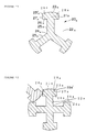
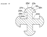
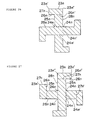
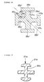
- FIGs 11 to 29 there are shown cross-sectional representations of gap holding rods (20a-20p).
- the gap holding rods comprise, where indicated, a plurality of both protruding portions (21a-21p) and recessed portions (22a-22p).
- the gap holding rods (20a-20p) are, in cross-section, substantially cruciform (see Figs 21-19, 22 and 24-29), Y-shaped (see Figs 11 and 23), or sinuous (see Figs 20 and 21).
- the gap holding rod is internally fitted into the suction port and is formed with the protruded portions and the recessed portions.
- the suction port can be invariably kept clear, and, even if the contents-filled sealed bag (or the innermost layer in the laminated container) is closely fitted to the gap holding rod, the passageway for the contents can be kept clear. Hence, substantially the whole quantity of the contents can be smoothly and surely poured out of the container.
- the protruded portion has the width larger than the opening of the recessed portion of the gap holding rod, if the gap holding rods are brought into close contact with each other, there is eliminated such a possibility that the protruded portion of other gap holding rod can intrude into the recessed portion.
- the gap holding rod is formed by contour extrusion, it can be cut to predetermined lengths. Hence production costs can be kept down.
- the outer peripheral surface of the suction portion is formed with grooves, passageways for the contents can be secured when the sealed bag, (or innermost layer in the laminated container) fits closely to the suction portion. Consequently substantially the entire contents of the sealed bag can be pumped out.
Landscapes
- Containers And Packaging Bodies Having A Special Means To Remove Contents (AREA)
- Closures For Containers (AREA)
- Reciprocating Pumps (AREA)
Abstract
Description
- The present invention relates generally to a pump device for a container and, more particularly, to a pump device for a container wherein the pump device is capable of delivering substantially the entire contents of the container.
- FIG. 30 illustrates a known container for pouring out contents having a high viscosity or contents altering in viscosity upon contact with the outside air.
- This container 1 includes a flexible content-filled sealed
bag 2 housed in the interior thereof, and apump 4 mounted in a mouthcylindrical portion 3. Thispump 4 is equipped with anoperating portion 5 exposed to the outside of the container 1 and asuction portion 6 inserted into the sealedbag 2. Thesuction portion 6 takes a pipe-like shape, is formed with a suction port 6a opened at a front edge thereof, and extends to an area in the vicinity of a bottom of the sealedbag 2. - In this container 1, after the
operating portion 5 is moved downward, theoperating portion 5 rises due to a spring, with the result that the interior of thesuction portion 6 is subjected a negative pressure.Contents 7 in the sealedbag 2 are thereby sucked via the suction port 6a into the pump. When theoperating portion 5 is again lowered, the contents sucked into the pump are poured out of adischarge port 5a formed in theoperating portion 5. Thus, thecontents 7 in the sealedbag 2 can be poured out by sequentially sucking them into thepump 4 and out of thedischarge port 5a. - With a conventional container, however, though there would be no problems at the beginning of its use. However, when the
contents 7 are reduced, the sealedbag 2 fits closely to thesuction portion 6. This results in the blockage of the suction port 6a. For this reason, there arises a problem in which the pump can not be completely restored, and thecontents 7 are left in the sealed bag. - Further, as the sealed
bag 2 fits closely to thesuction portion 6, thecontents 7 present in an upper area of the sealedbag 2 are hindered from flowing to the suction port 6a of thesuction portion 6, and thus thecontents 7 stay in the upper area due to a local shrinkage of the bottom of the sealedbag 2 in combination therewith. Thus, it is uneconomical that thecontents 7 stay in the upper area of the sealedbag 2. - JP-A-5-319467 seeks to alleviate the problem of the sealed bag coming into too close contact with the suction pipe by providing a cylindrical suction pipe with suction holes in a side wall thereof. An alternative solution is proposed in JP-A-5-319468 wherein a finned rod surmounted by a cylindrical member extends from the suction port.
- It is a primary object of the present invention, which was devised in view of the above problems inherent in the prior art, to provide a pump device for a container that exhibits an excellent productivity and is capable of smoothly surely pouring out contents by preventing a suction port of a sealed bag from being blocked and enabling the pouring out the whole quantity of contents.
- According to the present invention there is provided a pump device for a container, used by attaching said pump device to a container having a contents filled sealed bag contracting with a negative pressurisation of an interior thereof when taking out the contents thereof, said pump device comprising:
- an operating portion, an upper edge of which is exposed to an outside of said container; a suction portion having a flange formed in an upper portion thereof and being fixed in use to said container by a cap screwed onto a cylindrical mouth of said container from above said flange, a lower end of said suction portion being inserted into said container in use and sucking the contents from a suction port opened at a lower edge of said suction portion, said suction portion having a plurality of cylindrical portions of decreasing diameter starting below said flange, and a piston movable upward and downward within an upper cylindrical portion with the moving of said operating portion, said piston having a piston packing slidably contacting an internal surface of said upper cylindrical portion;
- a plurality of first protruding portions extending in the direction of the axis of said upper cylindrical portion and alternately formed circumferentially on an outer peripheral surface of said upper cylindrical portion;
- a plurality of second protruding portions and second recessed portions extending in the direction of the axis of the others of said cylindrical portions other than said upper cylindrical portion and alternately formed circumferential on outer peripheral surfaces of said others of said cylindrical portions;
- a gap holding rod having a proximal end internally fitted into said suction port of said suction portion and a distal end extending in use towards an inner bottom portion of said contents filled sealed bag; and
- third protruding portions and third recessed portions extending from said proximal end of said gap holding rod toward said distal end and being alternately formed on an outer peripheral surface of said gap holding rod.
-
- In a preferred embodiment the piston is cylindrical and the piston packing is movably mounted to said piston. Preferably also the pump device includes a valve which, in use, allows a portion of the contents of the container to enter the pump device. The valve may comprise a ball and a seat. In a preferred embodiment the operating portion comprises a head member and a discharge port and the piston, piston packing and head member are biased upwardly by a spring provided within the pump device.
- Preferably the suction port is retained within a lower cylindrical portion of the suction portion by a circumferential protrusion provided upon an inner surface of said lower cylindrical portion. The gap holding rod may have a uniform cross-sectional dimension along its entire length and may be formed by extrusion. The gap holding rod may be formed by the removal of material from a cylindrical rod and may be cruciform, Y-shaped or sinuous in cross-section. The container may comprise a laminated container and, in use, an inner layer of said laminated container defines said contents filled sealed bag.
- To obviate the problem given above, the present invention adopts the following construction.
- More specifically, in a pump device for a container, used by attaching the pump device to the container having a contents-filled sealed bag contracting with a negative pressurisation of an interior thereof when taking out the contents, the pump device has an operating portion exposed to the outside of the container and a suction portion, inserted into the container, for sucking the contents out of a suction port. The pump device for the container further comprises a gap holding rod having its proximal end internally fitted into the suction port of the suction portion and its distal end extending toward an inner bottom portion of the contents-filled sealed bag. Protruded portions and recessed portions extending from the proximal end of the gap holding rod toward the distal end thereof are formed alternately in a circumferential direction on an outer peripheral surface of the gap holding rod.
- The gap holding rod is, it can be considered, in terms of a sectional configuration thereof, constructed such that at least all the outermost-positioned protruded portion outermost sides of each of the protruded portions take outwardly-convex circular arcs or straight lines.
- In the container (corresponding to an innermost layer in a so-called laminated container) having the contents-filled sealed bag contracting with the internal negativepressurisation when taking out the contents, the interior of the container is depressurised as the contents are poured out. Hereupon, the contents-filled sealed bag is pulled in by the negative pressure with an exfoliation from an outer layer thereof, and consequently only an inner layer turns to be a bag and is then deformed by the contraction.
- In a state where the gap holding rod is mounted in the suction port of the suction portion, the suction port is invariably kept clear. Even if the contents-filled sealed bag is closely fitted to the gap holding rod, the contents-filled sealed bag is not, though closely fitted to the protruded portion of the gap holding rod, closely fitted to the recessed portion. Hence, this recessed portion is secured as a passageway for the contents Accordingly, even when the contents are reduced, the contents can be surely sucked. The gap holding rod may also be, though internally fitted in the suction port and fixed thereto, mounted in the suction port through a mounting connection pipe.
- Given herein is an explanation about a difference between operation characteristics depending on whether the protruded portion outermost sides of the gap holding rod take a circular arc or a straight line in terms of the sectional configuration .
- As described above, the contents-filled sealed bag used in the present invention is composed of a soft material exhibiting a flexibility. Therefore, the operation for securing the passageways for the contents depends on not only the material of the sealed hag and the viscosity of the contents but also the sectional configuration of the gap holding rod. The following are respective examinations which will be made.
- (A) To start with, when adopting a more flexible material of the sealed bag (innermost layer), and if the opening of the recessed portion is too large, the closefitting may easily happen even in the recessed portion, and the passageway is hard to secure.
- (B) Next, if the contents are highly viscous, the operating portion is required to rise more quickly in order to lead the contents into the recessed portions and suck them up.
- (C) Further, in terms of the sectional configuration, the passageways for the contents should be concentrated on the recessed portions as much as possible. For example, if a passageway is formed in a gap between the protruded portion outermost sides of the gap holding rod and the scaled bag (innermost layer), the passage diverges, and as a result a perimeter of the section of the passageway is long for a sum of the sectional areas of the passageway secured (a surface area of an internal wall of the passageway increasing even at the same flow rate). A loss to friction increases correspondingly, resulting in a rise of so-called pump loss.
- One of measures for obviating the above problems (B) and (C) may be, it can be considered, utilising a stronger spring with a greater spring constant. Such a measure, however, needs a larger operating force. Further, if the sectional area of the passageway is merely increased, it follows that the problem (A) may happen. Even under such conditions, it is desirable that the gap holding rod he formed in such a configuration as to expect that the contents are effectively transferred into the recessed portions by the protruded portions and effectively led from the protruded portions due to the recessed portions.
- Further, in the case of the soft sealed bag, each time it closely fits to the gap holding rod and separates therefrom, the soft sealed bag is repeatedly damaged by the edge of the protruded portion outermost side. It is therefor difficult to adopt the soft sealed bag. As in the case of the present invention, however, this can be prevented by using the protruded portion outermost side assuming the outwardly-convex protruded portion outermost side.
- On the other hand, if the protruded portion outermost side is defined as a straight line in the sectional configuration, the gap holding rod can be formed by a moulding method other than a contour extrusion moulding method using a dedicated die. For instance, the gap holding rod is formed by joining pre-cast tabular mouldings with their sides each defined as a straight line in terms of the sectional configuration thereof. According to this method, the gap holding rod can be designed without being machined by manufacturing equipment.
- The pump device according to the present invention is also established with an addition of constructive elements which will be given as follows.
- First, there is employed the gap holding rod formed by the contour extrusion moulding method. The gap holding rod can be formed by the contour extrusion moulding method, cut off to a predetermined length and then used. This leads to a remarkably high productivity, and a reduction in costs can be attained.
- Note that the contour extrusion moulding method is a method of forming a special shape product by heat pressurising a thermoplastic material in an extruder and consecutively extruding it from the die, while the special shape product is an unshaped elongate extruded product that is not included in shaped products having sectional configurations such as a circle, a rectangle and a regular polygon.
- Next, a swelling is formed at the front edge of each protruded portion of the gap holding rod. The gap holding rod is in an unstable state till it is extruded from the die by the contour extrusion moulding method and hardened by cooling but enhances in terms of its configurational retentivity thereof during that period by forming the above swelling.
- Moreover, an outer peripheral surface of the suction portion is formed with grooves extending in such a direction as to get close to the suction port. The configuration of the groove is not particularly limited.
- When the contents-filled sealed bag is closely fitted to the suction portion, and even if the contents stay in an upper area higher than the close-fitting portion thereof, the grooves formed in the outer peripheral surface of the suction portion are secured in the form of the passageways for the contents. Accordingly, the contents remaining in the upper area in the contents-filled sealed bag flow to the suction port. It is therefore possible to pour out substantially the whole quantity of contents to the very last content.
-
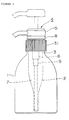
- FIG. 1 is an assembly outside view illustrating a suction portion and a gap holding rod of a pump device in an embodiment I of the present invention;
- FIG. 2 is a an assembly outside view showing a state where the pump device in the embodiment 1 is mounted in a container;
- FIG. 3 is a principal enlarged vertical sectional view illustrating a suction portion of the pump device in the embodiment 1;
- FIG. 4 is a sectional view taken substantially along the line A-A of FIG. 3;
- FIG. 5 is a sectional view taken substantially along the line B-B of FIG. 3;
- FIG. 6 is a sectional view taken substantially along the line C-C of FIG. 3;
- FIG. 7 is a sectional view taken substantially along the line D-D of FIG. 3;
- FIG. 8 is a cross-sectional view of the gap holding rod in the embodiment 1 as well as being a sectional view taken substantially along the line E-E of FIG. 1;
- FIG. 9 is a cross-sectional view illustrating a gap holding rod in another embodiment of the present invention;
- FIG. 10 is a cross-sectional view illustrating a gap holding rod in still another embodiment of the present invention;
- FIG. 11 is a cross-sectional view illustrating a gap holding rod in yet another embodiment of the present invention;
- FIG. 12 is a cross-sectional view illustrating a gap holding rod in a further embodiment of the present invention;
- FIG. 13 is a cross-sectional view illustrating a gap holding rod in a still further embodiment of the present invention;
- FIG. 14 is a cross-sectional view illustrating a gap holding rod in a yet further embodiment of the present invention;
- FIG. 15 is a cross-sectional view illustrating a gap holding rod in an additional embodiment of the present invention;
- FIG. 16 is a cross-sectional view illustrating a gap holding rod in a further additional embodiment of the present invention;
- FIG. 17 is a cross-sectional view illustrating a gap holding rod in a yet additional embodiment of the present invention;
- FIG. 18 is a cross-sectional view illustrating a gap holding rod in another embodiment of the present invention;
- FIG. 19 is a cross-sectional view illustrating a gap holding rod in another embodiment of the present invention;
- FIG. 20 is a cross-sectional view illustrating a gap holding rod in another embodiment of the present invention;
- FIG. 21 is a cross-sectional view illustrating a gap holding rod in another embodiment of the present invention;
- FIG. 22 is a cross-sectional view illustrating a gap holding rod in another embodiment of the present invention;
- FIG. 23 is a cross-sectional view illustrating a gap holding rod in another embodiment of the present invention;
- FIG. 24 is a cross-sectional view illustrating a gap holding rod in another embodiment of the present invention;
- FIG. 25 is a cross-sectional view illustrating a gap holding rod in another embodiment of the present invention;
- FIG. 26 is a cross-sectional view illustrating a gap holding rod in another embodiment of the present invention;
- FIG. 27 is a cross-sectional view illustrating a gap holding rod in another embodiment of the present invention;
- FIG. 28 is a cross-sectional view illustrating a gap holding rod in another embodiment of the present invention;
- FIG. 29 is a cross-sectional view illustrating a gap holding rod in another embodiment of the present invention; and
- FIG. 30 is an assembly outside view illustrating a pump device and a container in the prior art.
-
- Embodiments of the present invention will be discussed with reference to FIGS. I through 28.
- As illustrated in FIG. 2, a
pump device 4 is fitted in acylindrical mouth 3 of a container 1. A contents-filled sealed bag (hereinafter simply referred to as a sealed bag) exhibiting elasticity is accommodated in an interior of the container 1, the sealedbag 2 being filled withcontents 7. - This
pump device 4 includes an operating portion an upper edge of which is exposed to the outside of the container 1 and a suction portion 6 a majority of which, except for the upper edge thereof, is inserted into the sealedbag 2. - The
suction portion 6 comprises a connectingunit 8 exposed from the container 1 and acylindrical unit 9 fixed to the connectingunit 8. - The
suction portion 6 has a packing 30 interposed between aflange 10 and thecylindrical mouth 3 of the container 1, and acap 31 screwable onto thecylindrical mouth 3 from above theflange 10, to fix thesuction portion 6 to the container 1. - A lower portion of the
flange 10 is, as depicted in FIG. 3, is formed with a firstcylindrical portion 13a a secondcylindrical portion 13b, a thirdcylindrical portion 13c, a fourthcylindrical portion 13d, a fifthcylindrical portion 13e and a sixthcylindrical portion 13f, their diameters decreasing from theflange 10 downwards. Steppedportions cylindrical portion cylindrical portions cylindrical portions - FIGS. 4 through 7 are enlarged cross-sectional views illustrating the second
cylindrical portion 13b, the fourthcylindrical portion 13d, the fifthcylindrical portion 13e and the sixthcylindrical portion 13f, respectively. Protrudingportions 15acylindrical portion 13b, the fourthcylindrical portion 13d, the fifthcylindrical portion 13e and the sixthcylindrical portion 13f. - The number and dimensions of those protruding portions 15 - 15d and the recessed
portions 16a - 16d are set so that the contents flow at a predetermined flow rate through liquid passageways formed between the sealedbag 2 and the individual recessedportions 16a - 16d even when the sealedbag 2 is brought into close contact with thecylindrical unit 9. - Further, as will be mentioned later, an internal surface of the first
cylindrical portion 13b serves as a slide surface for a piston packing 34. However, the multiplicity of small protrudingportions 15a and recessedportions 16a are formed on the outer peripheral surface of the firstcylindrical portion 13b, and, therefore, a "sink mark" is not formed in the internal surface of the firstcylindrical portion 13b when moulded. Thus a liquid tight seal can be made between the piston packing 34 and the internal surface of the firstcylindrical portion 13b. Accordingly, thispump device 4 is highly efficient. - If a "sink mark" is formed in the internal surface of the first
cylindrical portion 13b, a gap is produced between the internal surface of the firstcylindrical portion 13b and the piston packing 34, with the result that the negative pressure needed for the suction may not be attained and the pump efficiency declines. - A
suction portion 17 is opens at a lower edge of the sixthcylindrical portion 13f, and thecontents 7 in the sealedbag 2 can enter thepump device 4 via thissuction portion 17. - The operating
portion 5 of thepump device 4 is constructed of ahead member 32 formed with adischarge port 32a and apiston 33 linked to thehead member 32 and movable up and down within thesuction portion 6. Thepiston 33 has a bottomed cylindrical shape, and further has a liquid passageway formed in its interior, and is connected to thedischarge port 32a of thehead member 32. - The piston packing 34 is slidably provided between the
piston 33 and the internal surface of the secondcylindrical portion 13b. Thehead member 32, thepiston 33 and the piston packing 34 are biased upward by aspring 35 provided within thecylindrical unit 9. - FIG. 1 illustrates a position where the
head member 32 is screwed to the connectingunit 8, and thepiston 33 is thus made unmovable. When thehead member 32 is screwed off the connectingunit 8, however, thehead member 32, thepiston 33 and the piston packing 34 are raised by dint of a spring force of thespring 35, and thehead member 32 moves to the position shown by two-dotted lines in FIG. 2. - A ball 36 for opening and closing a
valve port 19 is housed in a lower area in thecylindrical unit 9. Aliquid passageway 37 is provided between an outer edge portion of the bottom surface of thepiston 33 and the internal surface of the secondcylindrical portion 13b, while aliquid passage hole 38 is formed in thepiston 33 upstream of theliquid passageway 37. - When the
head member 32, thepiston 33 and the piston packing 34 are moved upward by the spring force of thespring 35, the piston packing 34 is raised while blocking theliquid passageway 37. As a result, the ball 36 is lifted by the negative pressure, and thevalve port 19 is opened, with the result that thecontents 7 flow via thesuction port 17 to a temporary reservingchamber 39 positioned downwardly of thepiston 33. - Thereafter, when the
head member 32, thepiston 33 and the piston packing 34 are lowered down against the spring force of thespring 35, the ball 36 closes thevalve port 19, and, at the same time, the piston packing 34 separates from the bottom surface of thepiston 33 to open theliquid passageway 37. As a result, the content liquid runs through theliquid passageway 37 from the temporary reservingchamber 39 and flows into thepiston 33 via theliquid passage hole 38. The content liquid is then delivered out of thedischarge port 32a of thehead member 32. - Further, a proximal end of a
gap holding rod 20 is internally fitted in the sixthcylindrical portion 13f and projects from thesuction port 17. Thegap holding rod 20 takes a rod-like shape and is formed in the same cross-sectional configuration throughout its entire length. - Moreover, a major diameter of the above circumscribed circle assuming the sectional configuration given- above is set slightly smaller than a minor diameter of the
suction portion 17 but a little bit larger than a minor diameter of a removalpreventive protrusion 18 provided on an inner peripheral surface of the sixthcylindrical portion 13f, the arrangement being such that it is internally tightly fitted in the removalpreventive protrusion 18 and fixed thereto when the proximal end of thegap holding rod 20 is inserted into thesuction port 17. - A front edge of this
gap holding rod 20 extends toward the bottom of the container 1, i.e., toward the bottom of the sealedbag 2. - A high productivity and a reduction in costs can be attained by using the
gap holding rod 20 formed by a contour extrusion and cut off to a predetermined length. - Accordingly, even if the sealed
bag 2 is closely fitted to thegap holding rod 20 as thecontents 7 are reduced, the sealedbag 2 is closely fitted to each protrudedportion 21 of thegap holding rod 20 but can not be closely fitted to each recessedportion 22, and, hence, this recessedportion 22 provides a passageway for thecontents 7. Further, thesuction port 17 is also held in an opened state by thegap holding rod 20. - Accordingly, even when the
contents 7 are reduced, thecontents 7 can be surely sucked from thebag 20, and a rising return motion of the operatingportion 5 can be also performed. - In addition, even if the sealed
bag 7 is closely fitted to thesuction portion 6 with the result that thecontents 7 stay more upward that the closely-fitted area, the outer peripheral surface of thesuction portion 6 is formed with the protrudedportions 15a - 15d and the recessedportions 16a - 16d, and therefore the recessedportions 16a - 16d provide passageways. Consequently, thecontents 7 remaining upward of the sealedbag 2 come to flow into thesuction port 17. - FIGS. 8, 9 and 10 are enlarged cross-sectional views each showing the
gap holding rod 20. - The
gap holding rod 20 in these embodiments is constructed by alternately forming the protruded portions and the recessed portions in the circumferential direction, these convex and recessed portions extending in the longitudinal direction over the entire length thereof. FIG 8 shows an example of the gap holding rod, wherein the convex and recessed portions are provided by threes. FIG 9 illustrates an example thereof, wherein the convex and recessed portions are provided by fours. FIG. 10 shows an example thereof, wherein the convex and recessed portions are provided by sixes. - Further, the above recessed portions of the gap holding rod have no inward area having its width larger than the opening portion, and, on the occasion of moulding, it is therefore possible to adopt a method of cutting inward a pre-cast integral moulding such as an angular rod or the like from its outer peripheral portion.
- As discussed above, according to this
pump device 4, thecontents 7 can be sucked out of the sealedbag 2 till substantially the entire quantity of thecontents 7 are removed. - Further, this pump device is also useable with a laminated container. The term "laminated container" implies a laminated blow plastic container having at least a double-layered structure, wherein an innermost layer thereof can be exfoliated from an outer layer thereof, and hence its external appearance is prevented from being changed.
- In the laminated container, when the interior of container is depressurised as the contents are poured the innermost layer is pulled by sufficient negative pressure to be peeled off the outer layer thereof, and only the innermost layer turns out to be a bag and is deformed by contraction. In this laminated container, the innermost layer corresponds to the sealed bag in the embodiment discussed above.
- When this pump device is used for the laminated container, even if the sealed
bag 2 comes in close contact with thegap holding rod 20, thegap holding rod 20 acts in the same manner as that in the embodiment given above and the passageways remain for thecontents 7, whereby the whole quantity of thecontents 7 can be substantially completely sucked out. - Referring to Figs 11 to 29 there are shown cross-sectional representations of gap holding rods (20a-20p). The gap holding rods comprise, where indicated, a plurality of both protruding portions (21a-21p) and recessed portions (22a-22p). The gap holding rods (20a-20p) are, in cross-section, substantially cruciform (see Figs 21-19, 22 and 24-29), Y-shaped (see Figs 11 and 23), or sinuous (see Figs 20 and 21).
- As discussed above, according to the present invention, the gap holding rod is internally fitted into the suction port and is formed with the protruded portions and the recessed portions. With this construction, the suction port can be invariably kept clear, and, even if the contents-filled sealed bag (or the innermost layer in the laminated container) is closely fitted to the gap holding rod, the passageway for the contents can be kept clear. Hence, substantially the whole quantity of the contents can be smoothly and surely poured out of the container.
- Especially in the example where the protruded portion has the width larger than the opening of the recessed portion of the gap holding rod, if the gap holding rods are brought into close contact with each other, there is eliminated such a possibility that the protruded portion of other gap holding rod can intrude into the recessed portion.
- Further, where the gap holding rod is formed by contour extrusion, it can be cut to predetermined lengths. Hence production costs can be kept down. In addition where the outer peripheral surface of the suction portion is formed with grooves, passageways for the contents can be secured when the sealed bag, (or innermost layer in the laminated container) fits closely to the suction portion. Consequently substantially the entire contents of the sealed bag can be pumped out.
Claims (14)
- A pump device (4) for a container (1), used by attaching said pump device (4) to a container (1) having a contents-filled sealed bag (2) contracting with a negative-pressurization of an interior thereof when taking out contents thereof, said pump device (4) comprising:an operating portion (5), an upper edge of which is exposed to an outside of said container;a suction portion (6) having a flange (10) formed in an upper portion thereof and being fixed in use to said container (1) by a cap (31) screwed onto a cylindrical mouth (3) of said container (1) from above said flange (10), a lower end of said suction portion (6) being inserted into said container (1) in use and sucking the contents from a suction port (17) opened at a lower edge of said suction portion (6), said suction portion (6) having a plurality of cylindrical portions (13a-13f) of decreasing diameter starting below said flange (10), and a piston (33) movable upward and downward within an upper cylindrical portion (13b) with the moving of said operating portion (5), said piston (33) having a piston packing (34) slidably contacting an internal surface of said upper cylindrical portion (13b);a plurality of first protruding portions (15a) and first recessed portions (16a) extending in the direction of the axis of said upper cylindrical portion (13b) and alternately formed circumferentially on an outer peripheral surface of said upper cylindrical portion (13b);a plurality of second protruding portions (15b-15d) and second recessed portions (16b-16d) extending in the direction of the axis of others of said cylindrical portions (13d-13f) other than said upper cylindrical portion (13b) and alternately formed circumferentially on outer peripheral surfaces of said others of said cylindrical portions (13d-13f);a gap holding rod (20) having a proximal end internally fitted into said suction port (17) of said suction portion (6) and a distal end extending in use towards an inner bottom portion of said contents-filled sealed bag (2); andthird protruding portions (21) and third recessed portions (22) extending from said proximal end of said gap holding rod (20) toward said distal end and being alternately formed on an outer peripheral surface of said gap holding rod (20).
- The pump device of claim 1, wherein said piston (33) is cylindrical and said piston packing (34) is movably mounted to said piston (33).
- The pump device (4) of claim 2 including a valve (19) which, in use, allows a portion of the of the contents of the container (1) to enter the pump device (4).
- The pump device (4) of claim 3 wherein the valve (19) comprises a ball (36) and a seat.
- The pump device (4) of claim 3 or claim 4 wherein the operating portion comprises a head member (32) and a discharge port (32a).
- The pump device of claim 5 wherein the piston (33), piston packing (34) and head member (32) are biased upwardly by a spring 35 provided within the pump device (4).
- The pump device of claim 6 wherein the suction port (17) is retained within a lower cylindrical portion (13f) of the suction portion (6) by a circumferential protrusion provided upon an inner surface of said lower cylindrical portion (13f).
- The pump device (4) of claim 7 wherein the gap holding rod (20) has a uniform cross-sectional dimensions along its entire length.
- The pump device (4) of claim 8 wherein the gap holding rod (20) is formed by extrusion.
- The pump device (4) of claim 8 wherein the gap holding rod (20) is formed by the removal of material from a cylindrical rod.
- The pump device (4) of claim 9 or claim 10 wherein the gap holding rod (20) is cruciform in cross-section.
- The pump device (4) of claim 9 or claim 10 wherein the gap holding rod (20) is Y-shaped in cross-section.
- The pump device (4) of claim 9 or claim 10 wherein the gap holding rod (20) is sinuous in cross-section.
- The pump device (4) of any preceding claim wherein the said container (1) comprises a laminated container and, in use, an inner layer of said laminated container defines said contents filled sealed bag (2).
Applications Claiming Priority (10)
| Application Number | Priority Date | Filing Date | Title |
|---|---|---|---|
| JP7575594 | 1994-04-14 | ||
| JP75755/94 | 1994-04-14 | ||
| JP7575594 | 1994-04-14 | ||
| JP135854/94 | 1994-06-17 | ||
| JP13585494 | 1994-06-17 | ||
| JP13585494 | 1994-06-17 | ||
| JP306515/94 | 1994-12-09 | ||
| JP30651594 | 1994-12-09 | ||
| JP30651594 | 1994-12-09 | ||
| PCT/JP1995/000735 WO1995028336A1 (en) | 1994-04-14 | 1995-04-14 | Pump device for a container |
Publications (3)
| Publication Number | Publication Date |
|---|---|
| EP0701951A1 EP0701951A1 (en) | 1996-03-20 |
| EP0701951A4 EP0701951A4 (en) | 1996-12-18 |
| EP0701951B1 true EP0701951B1 (en) | 2000-03-22 |
Family
ID=27301927
Family Applications (1)
| Application Number | Title | Priority Date | Filing Date |
|---|---|---|---|
| EP95915323A Expired - Lifetime EP0701951B1 (en) | 1994-04-14 | 1995-04-14 | Pump device for a container |
Country Status (8)
| Country | Link |
|---|---|
| US (1) | US5746350A (en) |
| EP (1) | EP0701951B1 (en) |
| KR (1) | KR100313818B1 (en) |
| CN (1) | CN1062230C (en) |
| AU (1) | AU690670B2 (en) |
| CA (1) | CA2165185C (en) |
| DE (1) | DE69515767T2 (en) |
| WO (1) | WO1995028336A1 (en) |
Cited By (1)
| Publication number | Priority date | Publication date | Assignee | Title |
|---|---|---|---|---|
| EP2251094A1 (en) * | 2009-04-30 | 2010-11-17 | Lumson S.p.A. | Device for dispensing fluid substances enclosed in sealed conditions in a bag with guided deformation |
Families Citing this family (24)
| Publication number | Priority date | Publication date | Assignee | Title |
|---|---|---|---|---|
| JP4076612B2 (en) * | 1997-12-22 | 2008-04-16 | 大日本印刷株式会社 | Outlet with lid used for bags, etc. |
| JP3396226B2 (en) * | 1997-12-26 | 2003-04-14 | 三菱重工業株式会社 | Mouth stopper and irregular-shaped container using this |
| JP2003226375A (en) * | 2002-01-31 | 2003-08-12 | Yoshino Kogyosho Co Ltd | Applying container with comb |
| US7770756B2 (en) * | 2002-05-17 | 2010-08-10 | Lbp Manufacturing, Inc. | Bulk container assembly |
| US6736289B2 (en) * | 2002-05-17 | 2004-05-18 | Lbp Manufacturing, Inc. | Bulk container assembly |
| CN100496760C (en) * | 2004-02-20 | 2009-06-10 | 株式会社吉野工业所 | foaming agent sprayer |
| WO2005081922A2 (en) * | 2004-02-23 | 2005-09-09 | Atkinson Technologies, Inc. | Fluid discharge device and fluid delivery system including same |
| KR100569180B1 (en) * | 2004-04-29 | 2006-04-10 | 주식회사 종우실업 | Small hand pump |
| DE102004032976A1 (en) * | 2004-07-08 | 2006-02-09 | Gimelli Produktions Ag | Oral irrigator with two detachably connectable housings |
| WO2006015458A1 (en) * | 2004-08-11 | 2006-02-16 | Tekni-Plex Europe, Naamloze Vennotschap | Dispenser or vial pump and a tube and valve assembly used in such |
| US7007827B1 (en) * | 2004-12-01 | 2006-03-07 | Shih-Wei Li | Emulsion dispenser |
| USD569736S1 (en) * | 2006-11-06 | 2008-05-27 | Conopco Inc. | Combined bottle and pump |
| CN101214869B (en) * | 2007-01-04 | 2013-12-25 | 丁要武 | Vacuum packaging container |
| TW201515714A (en) * | 2007-05-30 | 2015-05-01 | Glaxo Group Ltd | Fluid dispenser |
| EP2669214B1 (en) * | 2009-07-09 | 2016-01-20 | Advanced Technology Materials, Inc. | Storage system with a blow molded collapsible liner |
| US20120085789A1 (en) * | 2010-10-07 | 2012-04-12 | Fres-Co System Usa, Inc. | Package system including a fitment with anti-flow blocking and shut-off valve for use with dispensing devices |
| TW201242670A (en) | 2010-11-23 | 2012-11-01 | Advanced Tech Materials | Liner-based dispenser |
| EP2681124A4 (en) | 2011-03-01 | 2015-05-27 | Advanced Tech Materials | EXTERNAL ENVELOPE AND INTERNAL BLOW MOLDED INTERNAL TRIM AND METHODS OF MANUFACTURING SAME |
| WO2013031546A1 (en) * | 2011-08-30 | 2013-03-07 | 東洋エアゾール工業株式会社 | Residual quantity reduction member |
| CN104903212A (en) * | 2012-11-02 | 2015-09-09 | 先科材料有限公司 | Dip tube assemblies and methods of manufacturing the same |
| JP6386903B2 (en) * | 2014-12-19 | 2018-09-05 | 株式会社ショーワ | Actuator and vehicle steering device |
| JP6930873B2 (en) | 2017-07-31 | 2021-09-01 | 株式会社吉野工業所 | Discharge pump |
| US10357790B1 (en) * | 2018-10-11 | 2019-07-23 | Promens Sa | Device for withdrawing and dispensing a viscous product, without taking in air |
| CN111017400A (en) * | 2019-12-13 | 2020-04-17 | 中山市海辉塑胶制品有限公司 | A squeezing mechanism for an oil and milk bottle |
Family Cites Families (8)
| Publication number | Priority date | Publication date | Assignee | Title |
|---|---|---|---|---|
| US3876115A (en) * | 1972-04-27 | 1975-04-08 | Plant Ind Inc | Double expansible bladder container |
| US4322020A (en) * | 1978-05-02 | 1982-03-30 | Raymond Stone | Invertible pump sprayer |
| US4286636A (en) * | 1979-07-19 | 1981-09-01 | The Coca-Cola Company | Dip tube and valve with quick-disconnect coupling for a collapsible container |
| DK0515556T3 (en) * | 1990-02-22 | 1995-12-18 | Procter & Gamble | Pouch-in-bottle bottle fluid dispenser with means for counteracting bag collapse introduced therein |
| US5513761A (en) * | 1992-05-11 | 1996-05-07 | Yoshino Kogyosho Co., Ltd. | Laminated bottle and pump device therefor |
| JP3014858B2 (en) * | 1992-05-14 | 2000-02-28 | 株式会社吉野工業所 | Pump mechanism for container |
| JP3025578B2 (en) * | 1992-05-14 | 2000-03-27 | 株式会社吉野工業所 | Pump mechanism for container |
| JP2575410Y2 (en) * | 1993-11-02 | 1998-06-25 | 東洋製罐株式会社 | Dispensing pump for containers with a deformable inner layer |
-
1995
- 1995-04-14 CN CN95190455A patent/CN1062230C/en not_active Expired - Lifetime
- 1995-04-14 US US08/564,096 patent/US5746350A/en not_active Expired - Lifetime
- 1995-04-14 AU AU22240/95A patent/AU690670B2/en not_active Expired
- 1995-04-14 CA CA002165185A patent/CA2165185C/en not_active Expired - Lifetime
- 1995-04-14 EP EP95915323A patent/EP0701951B1/en not_active Expired - Lifetime
- 1995-04-14 WO PCT/JP1995/000735 patent/WO1995028336A1/en not_active Ceased
- 1995-04-14 DE DE69515767T patent/DE69515767T2/en not_active Expired - Lifetime
- 1995-04-14 KR KR1019950705680A patent/KR100313818B1/en not_active Expired - Fee Related
Cited By (1)
| Publication number | Priority date | Publication date | Assignee | Title |
|---|---|---|---|---|
| EP2251094A1 (en) * | 2009-04-30 | 2010-11-17 | Lumson S.p.A. | Device for dispensing fluid substances enclosed in sealed conditions in a bag with guided deformation |
Also Published As
| Publication number | Publication date |
|---|---|
| CN1062230C (en) | 2001-02-21 |
| CA2165185A1 (en) | 1995-10-26 |
| EP0701951A1 (en) | 1996-03-20 |
| CN1128976A (en) | 1996-08-14 |
| EP0701951A4 (en) | 1996-12-18 |
| DE69515767D1 (en) | 2000-04-27 |
| US5746350A (en) | 1998-05-05 |
| AU2224095A (en) | 1995-11-10 |
| DE69515767T2 (en) | 2000-08-31 |
| AU690670B2 (en) | 1998-04-30 |
| WO1995028336A1 (en) | 1995-10-26 |
| KR100313818B1 (en) | 2002-11-22 |
| CA2165185C (en) | 2003-12-09 |
Similar Documents
| Publication | Publication Date | Title |
|---|---|---|
| AU690670B2 (en) | Pump device for a container | |
| EP0550772B1 (en) | Bottle of laminate structure and method of making said bottle | |
| US5513761A (en) | Laminated bottle and pump device therefor | |
| CA1280718C (en) | Pump and stopper apparatus | |
| EP1459989B1 (en) | Blow-molded container | |
| EP1547939B1 (en) | Fill-out container | |
| EP0177351A2 (en) | Method and apparatus for molding plastics container and the plastics container | |
| PL200210B1 (en) | Twist operable dispensing closure accommodating optional liner puncture feature | |
| CN1268920A (en) | Method for producing container and container with pressure equalisation openings | |
| US5476630A (en) | Method for manufacturing dental aspirators | |
| BR0300512B1 (en) | Hand-operated spray nozzle cup. | |
| US4635826A (en) | Tube container for receiving semifluid material | |
| GB1593084A (en) | Dispensing closures | |
| JP4243775B2 (en) | Blow molding housing | |
| ES2209486T3 (en) | LIPSTICK AND METHOD TO MANUFACTURE IT. | |
| US20170320641A1 (en) | Tube with throttle insert | |
| JP2003012050A (en) | Extraction container | |
| JP3437715B2 (en) | Pumping equipment for containers | |
| AU622564B2 (en) | Self-draining container | |
| EP0136104A2 (en) | Method for filling an aerosol can with a viscous product | |
| JP3569046B2 (en) | Pumping equipment for containers | |
| WO2004043820A1 (en) | Container closure and method for manufacturing said closure | |
| JPH09142517A (en) | Pumping device for container | |
| JPH0335750Y2 (en) | ||
| JPH08301332A (en) | Liquid spouting pump |
Legal Events
| Date | Code | Title | Description |
|---|---|---|---|
| PUAI | Public reference made under article 153(3) epc to a published international application that has entered the european phase |
Free format text: ORIGINAL CODE: 0009012 |
|
| 17P | Request for examination filed |
Effective date: 19960109 |
|
| AK | Designated contracting states |
Kind code of ref document: A1 Designated state(s): CH DE FR GB IT LI NL |
|
| A4 | Supplementary search report drawn up and despatched | ||
| AK | Designated contracting states |
Kind code of ref document: A4 Designated state(s): CH DE FR GB IT LI NL |
|
| 17Q | First examination report despatched |
Effective date: 19970401 |
|
| GRAG | Despatch of communication of intention to grant |
Free format text: ORIGINAL CODE: EPIDOS AGRA |
|
| GRAG | Despatch of communication of intention to grant |
Free format text: ORIGINAL CODE: EPIDOS AGRA |
|
| GRAH | Despatch of communication of intention to grant a patent |
Free format text: ORIGINAL CODE: EPIDOS IGRA |
|
| GRAH | Despatch of communication of intention to grant a patent |
Free format text: ORIGINAL CODE: EPIDOS IGRA |
|
| GRAA | (expected) grant |
Free format text: ORIGINAL CODE: 0009210 |
|
| AK | Designated contracting states |
Kind code of ref document: B1 Designated state(s): CH DE FR GB IT LI NL |
|
| REG | Reference to a national code |
Ref country code: CH Ref legal event code: NV Representative=s name: KELLER & PARTNER PATENTANWAELTE AG Ref country code: CH Ref legal event code: EP |
|
| REF | Corresponds to: |
Ref document number: 69515767 Country of ref document: DE Date of ref document: 20000427 |
|
| ET | Fr: translation filed | ||
| ITF | It: translation for a ep patent filed | ||
| PLBE | No opposition filed within time limit |
Free format text: ORIGINAL CODE: 0009261 |
|
| STAA | Information on the status of an ep patent application or granted ep patent |
Free format text: STATUS: NO OPPOSITION FILED WITHIN TIME LIMIT |
|
| 26N | No opposition filed | ||
| REG | Reference to a national code |
Ref country code: GB Ref legal event code: IF02 |
|
| PGFP | Annual fee paid to national office [announced via postgrant information from national office to epo] |
Ref country code: NL Payment date: 20040406 Year of fee payment: 10 |
|
| PGFP | Annual fee paid to national office [announced via postgrant information from national office to epo] |
Ref country code: CH Payment date: 20040416 Year of fee payment: 10 |
|
| PG25 | Lapsed in a contracting state [announced via postgrant information from national office to epo] |
Ref country code: LI Free format text: LAPSE BECAUSE OF NON-PAYMENT OF DUE FEES Effective date: 20050430 Ref country code: CH Free format text: LAPSE BECAUSE OF NON-PAYMENT OF DUE FEES Effective date: 20050430 |
|
| PG25 | Lapsed in a contracting state [announced via postgrant information from national office to epo] |
Ref country code: NL Free format text: LAPSE BECAUSE OF NON-PAYMENT OF DUE FEES Effective date: 20051101 |
|
| REG | Reference to a national code |
Ref country code: CH Ref legal event code: PL |
|
| NLV4 | Nl: lapsed or anulled due to non-payment of the annual fee |
Effective date: 20051101 |
|
| PGFP | Annual fee paid to national office [announced via postgrant information from national office to epo] |
Ref country code: GB Payment date: 20140409 Year of fee payment: 20 |
|
| PGFP | Annual fee paid to national office [announced via postgrant information from national office to epo] |
Ref country code: DE Payment date: 20140430 Year of fee payment: 20 Ref country code: IT Payment date: 20140415 Year of fee payment: 20 Ref country code: FR Payment date: 20140409 Year of fee payment: 20 |
|
| REG | Reference to a national code |
Ref country code: DE Ref legal event code: R071 Ref document number: 69515767 Country of ref document: DE |
|
| REG | Reference to a national code |
Ref country code: GB Ref legal event code: PE20 Expiry date: 20150413 |
|
| PG25 | Lapsed in a contracting state [announced via postgrant information from national office to epo] |
Ref country code: GB Free format text: LAPSE BECAUSE OF EXPIRATION OF PROTECTION Effective date: 20150413 |