EP0701891B1 - Method of making an injection molding nozzle - Google Patents
Method of making an injection molding nozzle Download PDFInfo
- Publication number
- EP0701891B1 EP0701891B1 EP95113864A EP95113864A EP0701891B1 EP 0701891 B1 EP0701891 B1 EP 0701891B1 EP 95113864 A EP95113864 A EP 95113864A EP 95113864 A EP95113864 A EP 95113864A EP 0701891 B1 EP0701891 B1 EP 0701891B1
- Authority
- EP
- European Patent Office
- Prior art keywords
- conductive material
- inner core
- assembly
- vacuum furnace
- injection molding
- Prior art date
- Legal status (The legal status is an assumption and is not a legal conclusion. Google has not performed a legal analysis and makes no representation as to the accuracy of the status listed.)
- Expired - Lifetime
Links
- 238000001746 injection moulding Methods 0.000 title claims abstract description 25
- 238000004519 manufacturing process Methods 0.000 title claims abstract description 17
- 239000004020 conductor Substances 0.000 claims abstract description 44
- 238000010438 heat treatment Methods 0.000 claims abstract description 42
- 238000005219 brazing Methods 0.000 claims abstract description 29
- 239000000463 material Substances 0.000 claims abstract description 24
- RYGMFSIKBFXOCR-UHFFFAOYSA-N Copper Chemical compound [Cu] RYGMFSIKBFXOCR-UHFFFAOYSA-N 0.000 claims abstract description 23
- 229910052802 copper Inorganic materials 0.000 claims abstract description 23
- 239000010949 copper Substances 0.000 claims abstract description 23
- 238000005266 casting Methods 0.000 claims abstract description 11
- 238000007711 solidification Methods 0.000 claims abstract description 9
- 230000008023 solidification Effects 0.000 claims abstract description 9
- 229910000990 Ni alloy Inorganic materials 0.000 claims abstract description 7
- 239000011261 inert gas Substances 0.000 claims abstract description 4
- 238000002844 melting Methods 0.000 claims description 23
- 230000008018 melting Effects 0.000 claims description 23
- QVGXLLKOCUKJST-UHFFFAOYSA-N atomic oxygen Chemical compound [O] QVGXLLKOCUKJST-UHFFFAOYSA-N 0.000 claims description 6
- 239000000155 melt Substances 0.000 claims description 6
- 239000001301 oxygen Substances 0.000 claims description 6
- 229910052760 oxygen Inorganic materials 0.000 claims description 6
- 238000001816 cooling Methods 0.000 claims description 5
- 238000003780 insertion Methods 0.000 claims description 5
- 230000037431 insertion Effects 0.000 claims description 5
- 238000003754 machining Methods 0.000 claims description 2
- 238000003466 welding Methods 0.000 claims 1
- 230000015572 biosynthetic process Effects 0.000 abstract description 3
- 238000000034 method Methods 0.000 description 5
- IJGRMHOSHXDMSA-UHFFFAOYSA-N Atomic nitrogen Chemical compound N#N IJGRMHOSHXDMSA-UHFFFAOYSA-N 0.000 description 4
- 229910000831 Steel Inorganic materials 0.000 description 4
- 239000010959 steel Substances 0.000 description 4
- 230000000712 assembly Effects 0.000 description 3
- 238000000429 assembly Methods 0.000 description 3
- 238000007789 sealing Methods 0.000 description 3
- XKRFYHLGVUSROY-UHFFFAOYSA-N Argon Chemical compound [Ar] XKRFYHLGVUSROY-UHFFFAOYSA-N 0.000 description 2
- 238000009792 diffusion process Methods 0.000 description 2
- 229910052757 nitrogen Inorganic materials 0.000 description 2
- 239000000843 powder Substances 0.000 description 2
- 230000001681 protective effect Effects 0.000 description 2
- 239000010935 stainless steel Substances 0.000 description 2
- 229910001220 stainless steel Inorganic materials 0.000 description 2
- 229910000881 Cu alloy Inorganic materials 0.000 description 1
- 229910001315 Tool steel Inorganic materials 0.000 description 1
- 229910052786 argon Inorganic materials 0.000 description 1
- 239000011324 bead Substances 0.000 description 1
- DMFGNRRURHSENX-UHFFFAOYSA-N beryllium copper Chemical compound [Be].[Cu] DMFGNRRURHSENX-UHFFFAOYSA-N 0.000 description 1
- 239000000919 ceramic Substances 0.000 description 1
- 229910010293 ceramic material Inorganic materials 0.000 description 1
- 238000005260 corrosion Methods 0.000 description 1
- 230000007797 corrosion Effects 0.000 description 1
- 230000000694 effects Effects 0.000 description 1
- 239000012777 electrically insulating material Substances 0.000 description 1
- CPLXHLVBOLITMK-UHFFFAOYSA-N magnesium oxide Inorganic materials [Mg]=O CPLXHLVBOLITMK-UHFFFAOYSA-N 0.000 description 1
- 239000000395 magnesium oxide Substances 0.000 description 1
- AXZKOIWUVFPNLO-UHFFFAOYSA-N magnesium;oxygen(2-) Chemical compound [O-2].[Mg+2] AXZKOIWUVFPNLO-UHFFFAOYSA-N 0.000 description 1
- 238000012986 modification Methods 0.000 description 1
- 230000004048 modification Effects 0.000 description 1
- 230000000284 resting effect Effects 0.000 description 1
- 238000004544 sputter deposition Methods 0.000 description 1
- 238000012546 transfer Methods 0.000 description 1
- 238000013022 venting Methods 0.000 description 1
Images

Classifications
-
- B—PERFORMING OPERATIONS; TRANSPORTING
- B29—WORKING OF PLASTICS; WORKING OF SUBSTANCES IN A PLASTIC STATE IN GENERAL
- B29C—SHAPING OR JOINING OF PLASTICS; SHAPING OF MATERIAL IN A PLASTIC STATE, NOT OTHERWISE PROVIDED FOR; AFTER-TREATMENT OF THE SHAPED PRODUCTS, e.g. REPAIRING
- B29C45/00—Injection moulding, i.e. forcing the required volume of moulding material through a nozzle into a closed mould; Apparatus therefor
- B29C45/17—Component parts, details or accessories; Auxiliary operations
- B29C45/26—Moulds
- B29C45/27—Sprue channels ; Runner channels or runner nozzles
-
- B—PERFORMING OPERATIONS; TRANSPORTING
- B23—MACHINE TOOLS; METAL-WORKING NOT OTHERWISE PROVIDED FOR
- B23P—METAL-WORKING NOT OTHERWISE PROVIDED FOR; COMBINED OPERATIONS; UNIVERSAL MACHINE TOOLS
- B23P15/00—Making specific metal objects by operations not covered by a single other subclass or a group in this subclass
- B23P15/007—Making specific metal objects by operations not covered by a single other subclass or a group in this subclass injection moulding tools
Definitions
- This invention relates generally to injection molding and more particularly to a method of manufacturing an injection molding nozzle having an integral heating element in which both brazing and casting are carried out in a single heating cycle of a vacuum furnace.
- Making an injection molding nozzle with an integral electrical heating element has many advantages such as improved heat transfer, reduced corrosion and longer operating life. It is well known to make such integral nozzles by first sealing the components together to form a space around a helical portion of an electrical heating element, usually by brazing in a vacuum furnace. The nozzle is then reinserted into the vacuum furnace to cast a conductive material such as copper into the sealed space around the helical portion of the heating element. In the previous methods, a conductive material such as a beryllium copper alloy was selected to have a lower melting temperature than the brazing material. Different variations of this method are described in the applicant's U.S.
- an object of the present invention to at least partially overcome the disadvantages of the prior art by providing a method of manufacturing an injection molding nozzle in which both brazing to seal the space around the heating element and casting the conductive material into the sealed space are carried out in a single controlled cycle of a vacuum furnace.
- the invention provides a method of manufacturing an integral heated injection molding nozzle having a rear end, a front end, an elongated inner core portion with a melt passage extending therethrough from the rear end, an outer collar portion encircling the inner core portion adjacent the rear end, an outer sleeve portion extending from the outer collar portion towards the front end, an electrical heating element with a helical portion wound around the inner core portion and a lead portion extending outwardly through the outer collar portion, a conductive portion extending around the helical portion of the heating element between the inner core portion and the outer sleeve portion, including the steps of forming an assembly by mounting an outer collar and the heating element onto an inner core, mounting an elongated outer sleeve in a position to form a space around the helical portion of the heating element between the outer sleeve and the inner core, applying brazing material to the joints between the inner core, the outer collar and the outer sleeve and brazing the assembly together
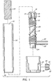
- Figure 1 is an exploded sectional view showing how the components of an injection molding nozzle are assembled according to a preferred embodiment of the invention
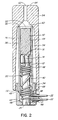
- Figure 2 is a sectional view of an assembly of these components with an insulative cap according to a first embodiment of the invention in place for insertion into a vacuum furnace,
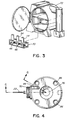
- Figure 3 shows a batch of these assemblies in position for insertion into the vacuum furnace
- Figure 4 is a view from the rear end of a completed injection molding nozzle made according to the preferred embodiment of the invention.
- Figure 5 is a view from the front end of the completed injection molding nozzle made according to the preferred embodiment of the invention.
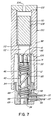
- Figure 6 is a sectional view along line 6-6 in Figures 4 and 5, and
- Figure 7 is a sectional view of an assembly of these components with an insulative cap according to a second embodiment of the invention in place for insertion into a vacuum furnace.
- FIG. 1 An electrical heating element 10 is wound around an elongated inner core 12 formed of a suitable material such as hot work tool steel.
- the inner core 12 has an enlarged head 14 at the upper end 16 (as shown) around which a number of spaced grooves 18 extend longitudinally to provide for the flow of molten conductive material therethrough, as described below.
- the electrical heating element 10 is wound with a helical portion 20 extending around the inner core 12 and two lead portions 22 extending outwardly near the lower end 24 of the inner core 12.
- the heating element 10 is wound with a predetermined configuration having fewer coils around the middle of the inner core 12 where there is less heat loss.
- the heating element 10 has a fine coiled resistance wire extending through an electrically insulating material such as magnesium oxide powder in an outer steel casing.
- an electrically insulating material such as magnesium oxide powder in an outer steel casing.
- other suitable types and configurations of heating elements can be used depending upon the thermal requirements of the application.
- a hollow outer collar 26 is mounted on the lower end 24 of the inner core 12 with the two lead portions 22 of the heating element 10 extending out through a radial opening 28 through the outer collar 26.
- a plug 30 having a pair of holes 32 to receive the lead portions 22 of the heating element 10 therethrough is then fitted into the radial opening 28.
- the outer collar 26 has an insulative flange portion 34 which supports the completed nozzle 36 without excessive heat loss when it is mounted in a cold mold (not shown).
- An elongated outer sleeve 38 made of a suitable protective material such as stainless steel is then mounted with its lower end 40 seated in the outer collar 26 to form a space 42 around the helical portion 20 of the heating element 10 between the inner core 12 and the surrounding outer sleeve 38.
- the outer sleeve 38 extends upwardly past the upper end 16 of the inner core 12 to form a cylindrical hopper 44 above the head 14 of the inner core 12.
- the inner core 12, outer collar 26, plug 30 and outer sleeve 38 are tack welded in place with a laser to form an assembly 46.
- an elongated insulative cap 54 is mounted on the assembly 46.
- the insulative cap 54 has a tapered central opening 56 with a downwardly open mouth 58 through which the assembly 46 is received.
- the central opening 56 has a shoulder 60 which tapers inwardly to a small vent bore 62 which extends upwardly to the upper end 64 of the insulative cap 54.
- the insulative cap 54 is removably supported in this position by the tapered shoulder 60 resting on the upper end 66 of the outer sleeve 38.
- the outer skirt 68 of the protective cap 54 extends downwardly around the flange portion 34 of the outer collar 26, leaving a lower portion 69 of the assembly 46 not covered by the insulative cap 54.
- a greater or lesser portion or the entire assembly can be covered by the insulative cap 54 as required to produce unidirectional solidification of the conductive material 50, as discussed below.
- the reusable insulative cap 54 is preferably made of a suitable ceramic material, although it can also be made of other suitable materials such as stainless steel.
- each assembly 46 is first brazed together to seal the space 42 around the heating element 10 and then the conductive material 50 is cast into the space 42 to form an integral injection molding heated nozzle 36.
- the furnace 72 is gradually heated it is evacuated to a relatively high vacuum to remove substantially all of the oxygen.
- the vent bores 62 in the insulative caps 54 ensure no oxygen is trapped inside the caps 54.
- the vacuum is then reduced by partially backfilling the furnace 72 with an inert gas such as argon or nitrogen to avoid sputtering.
- the furnace 72 is heated to a first temperature of approximately 1065°C (1950°F) which is above the melting point of the nickel alloy brazing material 48 and below the melting point of the copper conductive material 50. This melts the nickel alloy brazing material 48 which runs along the joints where it was applied between the heating element 10, inner core 12, plug 30, and outer sleeve 38.
- the temperature in the vacuum furnace is then lowered to a second temperature of approximately 982°C (1800°C) which is below the solidification temperature of the nickel alloy brazing material 48.
- This temperature is held for a sufficient period of time of approximately 30 minutes to braze the assembly 46 together to seal the space 42 around the helical portion 20 of the heating element 10 against leakage.
- the temperature in the vacuum furnace 72 is then raised to a third temperature of approximately 1113°C (2035°F) which is sufficiently above the melting temperature of the copper conductive material 50 to melt it, but not high enough to melt the diffusion brazes along the joints sealing the space 42.
- the copper conductive material 50 melts, it flows downwardly from the hopper 44 through the spaced grooves 18 in the head 14 of the inner core 12 to fill the space 42 around the helical portion 20 of the heating element 10 between the inner core 12 and outer sleeve 38.
- the controlled cycle of the vacuum furnace 72 is then completed by gradually cooling it down with a supply of inert gas such as nitrogen prior to removal of the integral cast nozzles 36.
- the insulative effect of the surrounding insulative cap 44 ensures that the copper conductive material 50 cools from the bottom up, thus producing unidirectional solidification from the bottom to the top. This avoids the formation of any voids due to shrinkage of the copper conductive material 50 during cooling and thus provides more efficient and uniform thermal conductivity from the heating element 10 to the melt flowing through the nozzle 36.
- Casting the copper conductive material 50 in a partial vacuum produces a metallurgical bonding of the copper conductive material 50 to the steel casing of the heating element 10 and the steel inner core 12, outer collar 26, and outer sleeve 38. Combined with the unidirectional solidification of the copper conductive material 50, this produces an integral injection molding heated nozzle 36 having very improved thermal characteristics.
- each nozzle 36 is machined to remove the upper portion 74 of the outer sleeve 38 which forms the hopper 44, and provide the completed nozzle 36 with a clean finish.
- the nozzle is also drilled to provide a central melt bore 76 extending therethrough from the rear end 78 to the front end 80 and to form a thermocouple element bore 82 extending forwardly from a groove 84 in the rear end 78. Threaded holes 86 are also provided in the rear end 78 to receive mounting screws. While the front end 80 of the nozzle 36 has been machined in this embodiment to form a cylindrical seat 88 to receive a gate insert (not shown), in other embodiments it can be machined to provide for various other gating configurations.
- the completed nozzle 36 has an inner core portion 90 through which the central melt bore 76 extends.
- the conductive portion 92 formed by the copper conductive material 50 is integrally bonded around the inner core portion 90 as well as to the heating element 10, the outer collar portion 94 with the plug 30 and the outer sleeve portion 96.
- the copper conductive material 50 also integrally fills the grooves 18 around the head 14 of the inner core 12 which improves the thermal conductivity near the front end 80 of the nozzle.
- the heated nozzle 36 is mounted in a cooled mold and melt flows through the central melt bore 76 to a gate leading to a cavity. While the use is the same as existing injection molding heated nozzles, the thermal performance of nozzles manufactured according to the present invention is considerably improved.
- the insulative cap 98 has an elongated hollow outer portion 100 with a lid 102 through which a vent bore 104 extends.
- the outer portion 100 has an inwardly extending shoulder 106 which sits on the upper end 66 of the outer sleeve 38.
- the insulative cap 98 rather than the outer sleeve 38 forms a hopper 108 into which the slug of copper 50 is inserted prior to insertion into the vacuum furnace 72.
- the slug of copper 50 rests on inwardly tapered ribs 110 to ensure proper venting of the space 112 beneath the slug of copper 50. Otherwise, the method of manufacture is the same as that described above except that there is no upper portion of the outer sleeve 38 which has to be removed after casting.
- the insulative cap 98 is merely removed and the nozzle 36 machined to provide the necessary finish.
- the insulative cap 98 is preferably made of ceramic and can be sprayed so the molten copper will not stick to it to facilitate reuse.
Abstract
Description
- This invention relates generally to injection molding and more particularly to a method of manufacturing an injection molding nozzle having an integral heating element in which both brazing and casting are carried out in a single heating cycle of a vacuum furnace.
- Making an injection molding nozzle with an integral electrical heating element has many advantages such as improved heat transfer, reduced corrosion and longer operating life. It is well known to make such integral nozzles by first sealing the components together to form a space around a helical portion of an electrical heating element, usually by brazing in a vacuum furnace. The nozzle is then reinserted into the vacuum furnace to cast a conductive material such as copper into the sealed space around the helical portion of the heating element. In the previous methods, a conductive material such as a beryllium copper alloy was selected to have a lower melting temperature than the brazing material. Different variations of this method are described in the applicant's U.S. Patent Numbers 4,355,460 which issued October 26, 1982, 4,403,405 which issued September 13, 1983, and 4,771,164 which issued September 13, 1988. While these previous methods have many advantages, they all have the disadvantage that the sealing of the space around the helical portion of the heating element and the casting of the copper into this space are two separate steps requiring two different cycles of the vacuum furnace. Furthermore, in the past, integrally casting the heating element in the conductive material has improved the extremely critical factor of thermal conductivity by reducing air pockets in the nozzle around the heating element. It has now been found that thermal conductivity can be further improved by cooling the nozzle in a manner to provide unidirectional solidification of the conductive material from the bottom up to prevent the formation of voids due to shrinkage.
- Accordingly, it is an object of the present invention to at least partially overcome the disadvantages of the prior art by providing a method of manufacturing an injection molding nozzle in which both brazing to seal the space around the heating element and casting the conductive material into the sealed space are carried out in a single controlled cycle of a vacuum furnace.
- It is a further object of the invention to provide a method of cooling the nozzle to produce unidirectional solidification of the conductive material in the space from the bottom.
- To this end, in one of its aspects, the invention provides a method of manufacturing an integral heated injection molding nozzle having a rear end, a front end, an elongated inner core portion with a melt passage extending therethrough from the rear end, an outer collar portion encircling the inner core portion adjacent the rear end, an outer sleeve portion extending from the outer collar portion towards the front end, an electrical heating element with a helical portion wound around the inner core portion and a lead portion extending outwardly through the outer collar portion, a conductive portion extending around the helical portion of the heating element between the inner core portion and the outer sleeve portion, including the steps of forming an assembly by mounting an outer collar and the heating element onto an inner core, mounting an elongated outer sleeve in a position to form a space around the helical portion of the heating element between the outer sleeve and the inner core, applying brazing material to the joints between the inner core, the outer collar and the outer sleeve and brazing the assembly together in a substantially oxygen free atmosphere in a vacuum furnace to seal said space against leakage when the assembly is in an upright position with the front end directly above the rear end, casting a molten conductive material into said space with the assembly in the upright position in a substantially oxygen free atmosphere in a vacuum furnace to form the conductive portion integrally bonded with the inner core portion, outer collar portion, heating element and outer sleeve portion, and machining the cast nozzle to provide a desired shape and finish, having the improvement wherein the conductive material has a melting temperature higher than the melting temperature of the brazing material, the assembly is brazed together and the conductive material is cast into said space in a single controlled cycle of the vacuum furnace which includes first raising the temperature in the vacuum furnace to a first predetermined temperature above the melting temperature of the brazing material and below the melting temperature of the conductive material, lowering the temperature in the vacuum furnace to a second predetermined temperature below the solidification temperature of the brazing material, holding the second temperature for a sufficient period of time to braze the assembly together, and then raising the temperature in the vacuum furnace to a third predetermined temperature sufficiently above the melting temperature of the conductive material to cast the conductive material into said space around the helical portion of the heating element between the outer sleeve and the inner core without melting the brazing material.
- Further objects and advantages of the invention will appear from the following description taken together with the accompanying drawings.
- Figure 1 is an exploded sectional view showing how the components of an injection molding nozzle are assembled according to a preferred embodiment of the invention,
- Figure 2 is a sectional view of an assembly of these components with an insulative cap according to a first embodiment of the invention in place for insertion into a vacuum furnace,
- Figure 3 shows a batch of these assemblies in position for insertion into the vacuum furnace,
- Figure 4 is a view from the rear end of a completed injection molding nozzle made according to the preferred embodiment of the invention,
- Figure 5 is a view from the front end of the completed injection molding nozzle made according to the preferred embodiment of the invention,
- Figure 6 is a sectional view along line 6-6 in Figures 4 and 5, and
- Figure 7 is a sectional view of an assembly of these components with an insulative cap according to a second embodiment of the invention in place for insertion into a vacuum furnace.
- Reference is first made to Figures 1 and 2 to describe how the components of an injection molding nozzle with an integral electrical heating element are assembled according to the invention. An
electrical heating element 10 is wound around an elongatedinner core 12 formed of a suitable material such as hot work tool steel. In this embodiment, theinner core 12 has an enlargedhead 14 at the upper end 16 (as shown) around which a number of spacedgrooves 18 extend longitudinally to provide for the flow of molten conductive material therethrough, as described below. Theelectrical heating element 10 is wound with ahelical portion 20 extending around theinner core 12 and twolead portions 22 extending outwardly near thelower end 24 of theinner core 12. Theheating element 10 is wound with a predetermined configuration having fewer coils around the middle of theinner core 12 where there is less heat loss. In this embodiment, theheating element 10 has a fine coiled resistance wire extending through an electrically insulating material such as magnesium oxide powder in an outer steel casing. In other embodiments, other suitable types and configurations of heating elements can be used depending upon the thermal requirements of the application. - Next, a hollow
outer collar 26 is mounted on thelower end 24 of theinner core 12 with the twolead portions 22 of theheating element 10 extending out through aradial opening 28 through theouter collar 26. Aplug 30 having a pair ofholes 32 to receive thelead portions 22 of theheating element 10 therethrough is then fitted into theradial opening 28. In this embodiment, theouter collar 26 has aninsulative flange portion 34 which supports the completednozzle 36 without excessive heat loss when it is mounted in a cold mold (not shown). - An elongated
outer sleeve 38 made of a suitable protective material such as stainless steel is then mounted with itslower end 40 seated in theouter collar 26 to form aspace 42 around thehelical portion 20 of theheating element 10 between theinner core 12 and the surroundingouter sleeve 38. As best seen in Figure 2, in this embodiment, theouter sleeve 38 extends upwardly past theupper end 16 of theinner core 12 to form acylindrical hopper 44 above thehead 14 of theinner core 12. During mounting, theinner core 12,outer collar 26,plug 30 andouter sleeve 38 are tack welded in place with a laser to form anassembly 46. - A suitable brazing material such as a nickel alloy is then applied along the joints between the
inner core 12, theheating element 10,plug 30 andouter sleeve 38 where indicated byreference numeral 48 in Figure 2. This is in the form of a bead along the outer joints and a powder along the inner joints. A slug of a suitableconductive material 50 is then loaded into thehopper 44 through its upperopen mouth 52. In this embodiment, theconductive material 50 is substantially pure copper which has a melting temperature of about 1082°C (1980°F) which is substantially higher than the melting temperature of the nickel alloy brazingmaterial 48 which is about 1010°C (1850°F). Other combinations of suitable materials can be used as long as theconductive material 50 has a melting temperature above the melting temperature of the brazingmaterial 48, and the brazed seal is not remelted by the casting temperature. After the slug ofconductive material 50 is loaded into thehopper 44, an elongatedinsulative cap 54 is mounted on theassembly 46. As clearly seen in Figure 2, in this embodiment, theinsulative cap 54 has a taperedcentral opening 56 with a downwardlyopen mouth 58 through which theassembly 46 is received. Thecentral opening 56 has ashoulder 60 which tapers inwardly to a small vent bore 62 which extends upwardly to theupper end 64 of theinsulative cap 54. Theinsulative cap 54 is removably supported in this position by thetapered shoulder 60 resting on theupper end 66 of theouter sleeve 38. As can be seen, in this embodiment, theouter skirt 68 of theprotective cap 54 extends downwardly around theflange portion 34 of theouter collar 26, leaving alower portion 69 of theassembly 46 not covered by theinsulative cap 54. In other embodiments, a greater or lesser portion or the entire assembly can be covered by theinsulative cap 54 as required to produce unidirectional solidification of theconductive material 50, as discussed below. The reusableinsulative cap 54 is preferably made of a suitable ceramic material, although it can also be made of other suitable materials such as stainless steel. - The
assemblies 46, each sitting in a rack 70 in the upright position shown in Figure 3 and covered by aninsulative cap 54, are then inserted in batches into avacuum furnace 72. While eachassembly 46 is shown having aseparate cap 54, a common cap having different openings therein can be mounted on a number of assemblies in a batch. During a single controlled cycle of thevacuum furnace 72, as described below, eachassembly 46 is first brazed together to seal thespace 42 around theheating element 10 and then theconductive material 50 is cast into thespace 42 to form an integral injection molding heatednozzle 36. As thefurnace 72 is gradually heated it is evacuated to a relatively high vacuum to remove substantially all of the oxygen. The vent bores 62 in theinsulative caps 54 ensure no oxygen is trapped inside thecaps 54. The vacuum is then reduced by partially backfilling thefurnace 72 with an inert gas such as argon or nitrogen to avoid sputtering. Thefurnace 72 is heated to a first temperature of approximately 1065°C (1950°F) which is above the melting point of the nickel alloy brazingmaterial 48 and below the melting point of the copperconductive material 50. This melts the nickel alloy brazingmaterial 48 which runs along the joints where it was applied between theheating element 10,inner core 12,plug 30, andouter sleeve 38. The temperature in the vacuum furnace is then lowered to a second temperature of approximately 982°C (1800°C) which is below the solidification temperature of the nickel alloy brazingmaterial 48. This temperature is held for a sufficient period of time of approximately 30 minutes to braze theassembly 46 together to seal thespace 42 around thehelical portion 20 of theheating element 10 against leakage. This produces a type of diffusion braze with the steel along the joints which has a melting temperature even higher than the melting temperature of the copperconductive material 50. - The temperature in the
vacuum furnace 72 is then raised to a third temperature of approximately 1113°C (2035°F) which is sufficiently above the melting temperature of the copperconductive material 50 to melt it, but not high enough to melt the diffusion brazes along the joints sealing thespace 42. When the copperconductive material 50 melts, it flows downwardly from thehopper 44 through thespaced grooves 18 in thehead 14 of theinner core 12 to fill thespace 42 around thehelical portion 20 of theheating element 10 between theinner core 12 andouter sleeve 38. As mentioned above, it is possible to cast the molten copperconductive material 50 into thespace 42 without it leaking out through the brazed joints because the melting temperature of the brazes or the brazingmaterial 48 along the joints is considerably higher after brazing than it was before. The controlled cycle of thevacuum furnace 72 is then completed by gradually cooling it down with a supply of inert gas such as nitrogen prior to removal of theintegral cast nozzles 36. The insulative effect of the surroundinginsulative cap 44 ensures that the copperconductive material 50 cools from the bottom up, thus producing unidirectional solidification from the bottom to the top. This avoids the formation of any voids due to shrinkage of thecopper conductive material 50 during cooling and thus provides more efficient and uniform thermal conductivity from theheating element 10 to the melt flowing through thenozzle 36. Casting thecopper conductive material 50 in a partial vacuum produces a metallurgical bonding of thecopper conductive material 50 to the steel casing of theheating element 10 and the steelinner core 12,outer collar 26, andouter sleeve 38. Combined with the unidirectional solidification of thecopper conductive material 50, this produces an integral injection moldingheated nozzle 36 having very improved thermal characteristics. - After removal from the
vacuum furnace 72, eachnozzle 36 is machined to remove theupper portion 74 of theouter sleeve 38 which forms thehopper 44, and provide the completednozzle 36 with a clean finish. As seen in Figure 6, the nozzle is also drilled to provide a central melt bore 76 extending therethrough from therear end 78 to thefront end 80 and to form a thermocouple element bore 82 extending forwardly from agroove 84 in therear end 78. Threadedholes 86 are also provided in therear end 78 to receive mounting screws. While thefront end 80 of thenozzle 36 has been machined in this embodiment to form acylindrical seat 88 to receive a gate insert (not shown), in other embodiments it can be machined to provide for various other gating configurations. As seen in Figure 5, the completednozzle 36 has aninner core portion 90 through which the central melt bore 76 extends. Theconductive portion 92 formed by thecopper conductive material 50 is integrally bonded around theinner core portion 90 as well as to theheating element 10, theouter collar portion 94 with theplug 30 and theouter sleeve portion 96. Thecopper conductive material 50 also integrally fills thegrooves 18 around thehead 14 of theinner core 12 which improves the thermal conductivity near thefront end 80 of the nozzle. - In use, the
heated nozzle 36 is mounted in a cooled mold and melt flows through the central melt bore 76 to a gate leading to a cavity. While the use is the same as existing injection molding heated nozzles, the thermal performance of nozzles manufactured according to the present invention is considerably improved. - Reference is now made to Figure 7 which shows the
insulative cap 98 having a different structure which is used in this embodiment of the invention. As most of the elements are the same as those described above, elements common to both embodiments are described and illustrated using the same reference numerals. In this embodiment, theinsulative cap 98 has an elongated hollowouter portion 100 with alid 102 through which avent bore 104 extends. Theouter portion 100 has an inwardly extendingshoulder 106 which sits on theupper end 66 of theouter sleeve 38. As can be seen, in this case theinsulative cap 98 rather than theouter sleeve 38 forms ahopper 108 into which the slug ofcopper 50 is inserted prior to insertion into thevacuum furnace 72. The slug ofcopper 50 rests on inwardly taperedribs 110 to ensure proper venting of thespace 112 beneath the slug ofcopper 50. Otherwise, the method of manufacture is the same as that described above except that there is no upper portion of theouter sleeve 38 which has to be removed after casting. Theinsulative cap 98 is merely removed and thenozzle 36 machined to provide the necessary finish. Theinsulative cap 98 is preferably made of ceramic and can be sprayed so the molten copper will not stick to it to facilitate reuse. - While the description of the method of manufacturing a heated
injection molding nozzle 36 according to the invention has been given with respect to preferred embodiments, it will be evident that various other modifications are possible without departing from the scope of the invention as defined in the following claims.
Claims (10)
- A method of manufacturing an integral heated injection molding nozzle (36) having a rear end (78), a front end (80), an elongated inner core portion (12) with a melt passage (76) extending therethrough from the rear end (78), an outer collar portion (26) encircling the inner core portion (12) adjacent the rear end (78), an outer sleeve portion (38) extending from the outer collar portion (26) towards the front end (80), an electrical heating element (10) with a helical portion (20) wound around the inner core portion (12) and a lead portion (22) extending outwardly through the outer collar portion (26), a conductive portion (92) extending around the helical portion (20) of the heating element (10) between the inner core portion (12) and the outer sleeve portion (38), including the steps of forming an assembly (46) by mounting an outer collar (26) and the heating element (10) onto an inner core (12), mounting an elongated outer sleeve (38) in a position to form a space (42) around the helical portion (20) of the heating element (10) between the outer sleeve (38) and the inner core (12), applying brazing material (48) to the joints between the inner core (12), the outer collar (26) and the outer sleeve (38) and brazing the assembly (46) together in a substantially oxygen free atmosphere in a vacuum furnace (72) to seal said space (42) against leakage when the assembly (46) is in an upright position with the front end (80) directly above the rear end (78), casting a molten conductive material (50) into said space (42) with the assembly (46) in the upright position in a substantially oxygen free atmosphere in a vacuum furnace (72) to form the conductive portion (92) integrally bonded with the inner core portion (12), outer collar portion (26), heating element (10) and outer sleeve portion (38), and machining the cast nozzle (36) to provide a desired shape and finish, characterized in that
the conductive material (50) has a melting temperature higher than the melting temperature of the brazing material (48), the assembly (46) is brazed together and the conductive material (50) is cast into said space (42) in a single controlled cycle of the vacuum furnace (72) which includes first raising the temperature in the vacuum furnace (72) to a first predetermined temperature above the melting temperature of the brazing material (48) and below the melting temperature of the conductive material (50), lowering the temperature in the vacuum furnace (72) to a second predetermined temperature below the solidification temperature of the brazing material (48), holding the second temperature for a sufficient period of time to braze the assembly (46) together, and then raising the temperature in the vacuum furnace (72) to a third predetermined temperature sufficiently above the melting temperature of the conductive material (50) to cast the conductive material (50) into said space (42) around the helical portion (20) of the heating element (10) between the outer sleeve (38) and the inner core (12) without melting the brazing material (48). - A method of manufacturing an injection molding nozzle (36) as claimed in claim 1 wherein the controlled cycle of the vacuum furnace (72) further includes the step of gradually cooling the vacuum furnace (72) with a supply of inert gas prior to removal of the cast nozzle (36).
- A method of manufacturing an injection molding nozzle (36) as claimed in claim 2 further including placing an insulative cap (54) having an elongated opening (56) with a downwardly open mouth (58) over the assembly (46) during the heating cycle in the vacuum furnace (72) with the assembly (46) extending upwardly into the opening (56), whereby the conductive material (50) cools progressively upwardly.
- A method of manufacturing an injection molding nozzle (36) as claimed in claim 3 wherein a predetermined portion of the assembly (46) extends upwardly into the opening in the insulative cap (54).
- A method of manufacturing an injection molding nozzle as claimed in claim 4 wherein the outer sleeve (38) extends upwardly past the front end (80) in the upright position to an upper end to form a hopper (44), and loading a predetermined quantity of the conductive material (50) into the hopper (44) prior to insertion of the assembly (46) into the vacuum furnace (72), whereby during casting in the vacuum furnace (72) the conductive material (50) melts and runs down into said space (42) around the helical portion (20) of the heating element (10) between the outer sleeve (38) and the inner core (12).
- A method of manufacturing an injection molding nozzle (36) as claimed in claim 5 wherein the insulative cap (54) is removably supported with a portion of the assembly (46) received in the opening (56) by contact against the upper end (66) of the outer sleeve (38).
- A method of manufacturing an injection molding nozzle (36) as claimed in claim 6 wherein the insulative cap (54) has a vent bore (62) extending upwardly from the opening (56) in which the assembly (46) is received.
- A method of manufacturing an injection molding nozzle (36) as claimed in claim 7 including attaching the inner core (12), the outer collar (26) and the outer sleeve (38) together by tack welding prior to brazing.
- A method of manufacturing an injection molding nozzle (36) as claimed in claim 8 wherein the conductive material (50) is copper.
- A method of manufacturing an injection molding nozzle (36) as claimed in claim 9 wherein the brazing material (48) is a nickel alloy.
Applications Claiming Priority (2)
| Application Number | Priority Date | Filing Date | Title |
|---|---|---|---|
| CA002132281A CA2132281C (en) | 1994-09-16 | 1994-09-16 | Method of making an injection molding nozzle |
| CA2132281 | 1994-09-16 |
Publications (3)
| Publication Number | Publication Date |
|---|---|
| EP0701891A2 EP0701891A2 (en) | 1996-03-20 |
| EP0701891A3 EP0701891A3 (en) | 1997-05-21 |
| EP0701891B1 true EP0701891B1 (en) | 2000-05-24 |
Family
ID=4154346
Family Applications (1)
| Application Number | Title | Priority Date | Filing Date |
|---|---|---|---|
| EP95113864A Expired - Lifetime EP0701891B1 (en) | 1994-09-16 | 1995-09-04 | Method of making an injection molding nozzle |
Country Status (9)
| Country | Link |
|---|---|
| EP (1) | EP0701891B1 (en) |
| JP (1) | JP3824336B2 (en) |
| CN (1) | CN1060416C (en) |
| AT (1) | ATE193240T1 (en) |
| CA (1) | CA2132281C (en) |
| DE (2) | DE69517111T2 (en) |
| ES (1) | ES2146687T3 (en) |
| IN (1) | IN192646B (en) |
| PT (1) | PT701891E (en) |
Families Citing this family (2)
| Publication number | Priority date | Publication date | Assignee | Title |
|---|---|---|---|---|
| CN102825433A (en) * | 2012-09-19 | 2012-12-19 | 哈尔滨电机厂有限责任公司 | Integral molding manufacturing process method of steam turbine generator copper shield |
| JP7042569B2 (en) * | 2017-07-28 | 2022-03-28 | ハイリマレリジャパン株式会社 | Manufacturing method of molds and cast parts |
Family Cites Families (5)
| Publication number | Priority date | Publication date | Assignee | Title |
|---|---|---|---|---|
| US4355460A (en) * | 1980-12-17 | 1982-10-26 | Gellert Jobst U | Sprue bushing and method of manufacture |
| CA1179813A (en) * | 1981-07-15 | 1984-12-27 | Jobst U. Gellert | Sprue bushing connector assembly and method |
| US4771164A (en) * | 1987-04-01 | 1988-09-13 | Gellert Jobst U | Injection molding nozzle and method |
| US5052100A (en) * | 1990-04-10 | 1991-10-01 | Panos Trakas | Method of making sprue bushing assembly with inner thermal sleeve |
| CA2057439C (en) * | 1991-12-11 | 2000-02-08 | Jobst Ulrich Gellert | Method of manufacturing an injection molding probe |
-
1994
- 1994-09-16 CA CA002132281A patent/CA2132281C/en not_active Expired - Fee Related
-
1995
- 1995-08-23 IN IN1086MA1995 patent/IN192646B/en unknown
- 1995-09-04 DE DE69517111T patent/DE69517111T2/en not_active Expired - Fee Related
- 1995-09-04 AT AT95113864T patent/ATE193240T1/en not_active IP Right Cessation
- 1995-09-04 EP EP95113864A patent/EP0701891B1/en not_active Expired - Lifetime
- 1995-09-04 ES ES95113864T patent/ES2146687T3/en not_active Expired - Lifetime
- 1995-09-04 DE DE19532608A patent/DE19532608B4/en not_active Expired - Fee Related
- 1995-09-04 PT PT95113864T patent/PT701891E/en unknown
- 1995-09-07 JP JP22993195A patent/JP3824336B2/en not_active Expired - Fee Related
- 1995-09-14 CN CN95116963A patent/CN1060416C/en not_active Expired - Fee Related
Also Published As
| Publication number | Publication date |
|---|---|
| IN192646B (en) | 2004-05-08 |
| ES2146687T3 (en) | 2000-08-16 |
| DE69517111D1 (en) | 2000-06-29 |
| CN1060416C (en) | 2001-01-10 |
| CA2132281C (en) | 2006-07-04 |
| CN1126642A (en) | 1996-07-17 |
| EP0701891A2 (en) | 1996-03-20 |
| JPH08150465A (en) | 1996-06-11 |
| CA2132281A1 (en) | 1996-03-17 |
| PT701891E (en) | 2000-09-29 |
| ATE193240T1 (en) | 2000-06-15 |
| DE19532608A1 (en) | 1996-03-21 |
| DE19532608B4 (en) | 2006-03-23 |
| DE69517111T2 (en) | 2000-09-21 |
| JP3824336B2 (en) | 2006-09-20 |
| EP0701891A3 (en) | 1997-05-21 |
Similar Documents
| Publication | Publication Date | Title |
|---|---|---|
| US4386262A (en) | Sprue bushing with cast in electrical heating element | |
| EP1121236B1 (en) | Apparatus and method of making an injection molding nozzle with tip insert | |
| US4611394A (en) | Method of manufacture of an injection molding integral heated probe | |
| JP2752452B2 (en) | Injection molding nozzle and its manufacturing method | |
| CA1163073A (en) | Injection molding heated probe | |
| EP0167977B2 (en) | Injection molding heated nozzle with brazed in heating element and method of manufacture | |
| US4355460A (en) | Sprue bushing and method of manufacture | |
| EP0083760B1 (en) | Injection molding manifold member and method of manufacture | |
| JPS6112089Y2 (en) | ||
| US5052100A (en) | Method of making sprue bushing assembly with inner thermal sleeve | |
| US5437093A (en) | Method of making an injection molding nozzle | |
| US5180594A (en) | Internally heated sprue bushing with thermally conductive sleeve | |
| JPS63254019A (en) | Heating type nozzle for injection molding equipment and manufacture thereof | |
| JPH02248229A (en) | Heat-injection molding nozzle | |
| JPH01136714A (en) | Manufacture of injection molding heating nozzle | |
| EP0546555B1 (en) | Method of manufacturing an injection molding probe | |
| EP0701891B1 (en) | Method of making an injection molding nozzle | |
| JP3016957B2 (en) | Distribution manifold for injection molding | |
| JP3085794B2 (en) | Manufacturing method of composite material | |
| JPH0278515A (en) | Injection molding device with insulating ring which can be inserted |
Legal Events
| Date | Code | Title | Description |
|---|---|---|---|
| PUAI | Public reference made under article 153(3) epc to a published international application that has entered the european phase |
Free format text: ORIGINAL CODE: 0009012 |
|
| AK | Designated contracting states |
Kind code of ref document: A2 Designated state(s): AT BE CH DE DK ES FR GB IE IT LI LU NL PT SE |
|
| PUAL | Search report despatched |
Free format text: ORIGINAL CODE: 0009013 |
|
| AK | Designated contracting states |
Kind code of ref document: A3 Designated state(s): AT BE CH DE DK ES FR GB IE IT LI LU NL PT SE |
|
| 17P | Request for examination filed |
Effective date: 19971009 |
|
| GRAG | Despatch of communication of intention to grant |
Free format text: ORIGINAL CODE: EPIDOS AGRA |
|
| 17Q | First examination report despatched |
Effective date: 19990716 |
|
| GRAG | Despatch of communication of intention to grant |
Free format text: ORIGINAL CODE: EPIDOS AGRA |
|
| GRAH | Despatch of communication of intention to grant a patent |
Free format text: ORIGINAL CODE: EPIDOS IGRA |
|
| GRAH | Despatch of communication of intention to grant a patent |
Free format text: ORIGINAL CODE: EPIDOS IGRA |
|
| GRAA | (expected) grant |
Free format text: ORIGINAL CODE: 0009210 |
|
| AK | Designated contracting states |
Kind code of ref document: B1 Designated state(s): AT BE CH DE DK ES FR GB IE IT LI LU NL PT SE |
|
| PG25 | Lapsed in a contracting state [announced via postgrant information from national office to epo] |
Ref country code: BE Free format text: LAPSE BECAUSE OF FAILURE TO SUBMIT A TRANSLATION OF THE DESCRIPTION OR TO PAY THE FEE WITHIN THE PRESCRIBED TIME-LIMIT Effective date: 20000524 |
|
| REF | Corresponds to: |
Ref document number: 193240 Country of ref document: AT Date of ref document: 20000615 Kind code of ref document: T |
|
| REG | Reference to a national code |
Ref country code: CH Ref legal event code: NV Representative=s name: PATENTANWALTSBUERO JEAN HUNZIKER Ref country code: CH Ref legal event code: EP |
|
| REG | Reference to a national code |
Ref country code: IE Ref legal event code: FG4D |
|
| REF | Corresponds to: |
Ref document number: 69517111 Country of ref document: DE Date of ref document: 20000629 |
|
| ITF | It: translation for a ep patent filed |
Owner name: MARCHI & PARTNERS S.R.L. |
|
| REG | Reference to a national code |
Ref country code: ES Ref legal event code: FG2A Ref document number: 2146687 Country of ref document: ES Kind code of ref document: T3 |
|
| PG25 | Lapsed in a contracting state [announced via postgrant information from national office to epo] |
Ref country code: SE Free format text: LAPSE BECAUSE OF FAILURE TO SUBMIT A TRANSLATION OF THE DESCRIPTION OR TO PAY THE FEE WITHIN THE PRESCRIBED TIME-LIMIT Effective date: 20000824 Ref country code: DK Free format text: LAPSE BECAUSE OF FAILURE TO SUBMIT A TRANSLATION OF THE DESCRIPTION OR TO PAY THE FEE WITHIN THE PRESCRIBED TIME-LIMIT Effective date: 20000824 |
|
| ET | Fr: translation filed | ||
| REG | Reference to a national code |
Ref country code: PT Ref legal event code: SC4A Free format text: AVAILABILITY OF NATIONAL TRANSLATION Effective date: 20000630 |
|
| PLBE | No opposition filed within time limit |
Free format text: ORIGINAL CODE: 0009261 |
|
| STAA | Information on the status of an ep patent application or granted ep patent |
Free format text: STATUS: NO OPPOSITION FILED WITHIN TIME LIMIT |
|
| 26N | No opposition filed | ||
| REG | Reference to a national code |
Ref country code: GB Ref legal event code: IF02 |
|
| REG | Reference to a national code |
Ref country code: CH Ref legal event code: PUE Owner name: MOLD-MASTERS (2007) LIMITED Free format text: GELLERT, JOBST ULRICH#7A PRINCE STREET#GEORGETOWN ONTARIO L7G 2X1 (CA) -TRANSFER TO- MOLD-MASTERS (2007) LIMITED#233 ARMSTRONG AVENUE#GEORGETOWN ON L7G4X5 (CA) |
|
| REG | Reference to a national code |
Ref country code: GB Ref legal event code: 732E |
|
| REG | Reference to a national code |
Ref country code: PT Ref legal event code: PC4A Owner name: MOLD-MASTERS (2007) LIMITED, CA Effective date: 20080819 |
|
| NLS | Nl: assignments of ep-patents |
Owner name: MOLD-MASTERS (2007) LIMITED Effective date: 20080610 |
|
| PGFP | Annual fee paid to national office [announced via postgrant information from national office to epo] |
Ref country code: PT Payment date: 20080825 Year of fee payment: 14 Ref country code: LU Payment date: 20080828 Year of fee payment: 14 Ref country code: ES Payment date: 20080924 Year of fee payment: 14 Ref country code: CH Payment date: 20080826 Year of fee payment: 14 |
|
| PGFP | Annual fee paid to national office [announced via postgrant information from national office to epo] |
Ref country code: NL Payment date: 20080827 Year of fee payment: 14 Ref country code: IT Payment date: 20080913 Year of fee payment: 14 Ref country code: IE Payment date: 20080826 Year of fee payment: 14 Ref country code: AT Payment date: 20080825 Year of fee payment: 14 |
|
| REG | Reference to a national code |
Ref country code: FR Ref legal event code: TP |
|
| PGFP | Annual fee paid to national office [announced via postgrant information from national office to epo] |
Ref country code: GB Payment date: 20080827 Year of fee payment: 14 |
|
| PGFP | Annual fee paid to national office [announced via postgrant information from national office to epo] |
Ref country code: DE Payment date: 20081002 Year of fee payment: 14 |
|
| PGFP | Annual fee paid to national office [announced via postgrant information from national office to epo] |
Ref country code: FR Payment date: 20080929 Year of fee payment: 14 |
|
| REG | Reference to a national code |
Ref country code: PT Ref legal event code: MM4A Free format text: LAPSE DUE TO NON-PAYMENT OF FEES Effective date: 20100304 |
|
| REG | Reference to a national code |
Ref country code: NL Ref legal event code: V1 Effective date: 20100401 |
|
| PG25 | Lapsed in a contracting state [announced via postgrant information from national office to epo] |
Ref country code: PT Free format text: LAPSE BECAUSE OF NON-PAYMENT OF DUE FEES Effective date: 20100304 |
|
| REG | Reference to a national code |
Ref country code: CH Ref legal event code: PL |
|
| GBPC | Gb: european patent ceased through non-payment of renewal fee |
Effective date: 20090904 |
|
| REG | Reference to a national code |
Ref country code: IE Ref legal event code: MM4A |
|
| REG | Reference to a national code |
Ref country code: FR Ref legal event code: ST Effective date: 20100531 |
|
| PG25 | Lapsed in a contracting state [announced via postgrant information from national office to epo] |
Ref country code: AT Free format text: LAPSE BECAUSE OF NON-PAYMENT OF DUE FEES Effective date: 20090904 |
|
| PG25 | Lapsed in a contracting state [announced via postgrant information from national office to epo] |
Ref country code: NL Free format text: LAPSE BECAUSE OF NON-PAYMENT OF DUE FEES Effective date: 20100401 Ref country code: IE Free format text: LAPSE BECAUSE OF NON-PAYMENT OF DUE FEES Effective date: 20090904 Ref country code: FR Free format text: LAPSE BECAUSE OF NON-PAYMENT OF DUE FEES Effective date: 20090930 Ref country code: DE Free format text: LAPSE BECAUSE OF NON-PAYMENT OF DUE FEES Effective date: 20100401 |
|
| PG25 | Lapsed in a contracting state [announced via postgrant information from national office to epo] |
Ref country code: LI Free format text: LAPSE BECAUSE OF NON-PAYMENT OF DUE FEES Effective date: 20090930 Ref country code: CH Free format text: LAPSE BECAUSE OF NON-PAYMENT OF DUE FEES Effective date: 20090930 |
|
| PG25 | Lapsed in a contracting state [announced via postgrant information from national office to epo] |
Ref country code: GB Free format text: LAPSE BECAUSE OF NON-PAYMENT OF DUE FEES Effective date: 20090904 |
|
| PG25 | Lapsed in a contracting state [announced via postgrant information from national office to epo] |
Ref country code: IT Free format text: LAPSE BECAUSE OF NON-PAYMENT OF DUE FEES Effective date: 20090904 |
|
| PG25 | Lapsed in a contracting state [announced via postgrant information from national office to epo] |
Ref country code: LU Free format text: LAPSE BECAUSE OF NON-PAYMENT OF DUE FEES Effective date: 20090904 |
|
| REG | Reference to a national code |
Ref country code: ES Ref legal event code: FD2A Effective date: 20110718 |
|
| PG25 | Lapsed in a contracting state [announced via postgrant information from national office to epo] |
Ref country code: ES Free format text: LAPSE BECAUSE OF NON-PAYMENT OF DUE FEES Effective date: 20110706 |
|
| PG25 | Lapsed in a contracting state [announced via postgrant information from national office to epo] |
Ref country code: ES Free format text: LAPSE BECAUSE OF NON-PAYMENT OF DUE FEES Effective date: 20090905 |