EP0701889A2 - Isostatic die for pressing ceramic tiles and method for manufacturing the tiles - Google Patents
Isostatic die for pressing ceramic tiles and method for manufacturing the tiles Download PDFInfo
- Publication number
- EP0701889A2 EP0701889A2 EP95202233A EP95202233A EP0701889A2 EP 0701889 A2 EP0701889 A2 EP 0701889A2 EP 95202233 A EP95202233 A EP 95202233A EP 95202233 A EP95202233 A EP 95202233A EP 0701889 A2 EP0701889 A2 EP 0701889A2
- Authority
- EP
- European Patent Office
- Prior art keywords
- die
- plate
- membrane
- cavity
- vulcanisation
- Prior art date
- Legal status (The legal status is an assumption and is not a legal conclusion. Google has not performed a legal analysis and makes no representation as to the accuracy of the status listed.)
- Granted
Links
Images


Classifications
-
- B—PERFORMING OPERATIONS; TRANSPORTING
- B28—WORKING CEMENT, CLAY, OR STONE
- B28B—SHAPING CLAY OR OTHER CERAMIC COMPOSITIONS; SHAPING SLAG; SHAPING MIXTURES CONTAINING CEMENTITIOUS MATERIAL, e.g. PLASTER
- B28B3/00—Producing shaped articles from the material by using presses; Presses specially adapted therefor
- B28B3/003—Pressing by means acting upon the material via flexible mould wall parts, e.g. by means of inflatable cores, isostatic presses
-
- B—PERFORMING OPERATIONS; TRANSPORTING
- B30—PRESSES
- B30B—PRESSES IN GENERAL
- B30B11/00—Presses specially adapted for forming shaped articles from material in particulate or plastic state, e.g. briquetting presses, tabletting presses
- B30B11/001—Presses specially adapted for forming shaped articles from material in particulate or plastic state, e.g. briquetting presses, tabletting presses using a flexible element, e.g. diaphragm, urged by fluid pressure; Isostatic presses
-
- B—PERFORMING OPERATIONS; TRANSPORTING
- B30—PRESSES
- B30B—PRESSES IN GENERAL
- B30B15/00—Details of, or accessories for, presses; Auxiliary measures in connection with pressing
- B30B15/02—Dies; Inserts therefor; Mounting thereof; Moulds
- B30B15/022—Moulds for compacting material in powder, granular of pasta form
- B30B15/024—Moulds for compacting material in powder, granular of pasta form using elastic mould parts
-
- B—PERFORMING OPERATIONS; TRANSPORTING
- B30—PRESSES
- B30B—PRESSES IN GENERAL
- B30B5/00—Presses characterised by the use of pressing means other than those mentioned in the preceding groups
- B30B5/02—Presses characterised by the use of pressing means other than those mentioned in the preceding groups wherein the pressing means is in the form of a flexible element, e.g. diaphragm, urged by fluid pressure
Definitions
- the invention concerns a die for pressing ceramic tiles and a relative manufacturing method.
- the prior art comprises Italian patent for industrial invention IT-B-1104511 in which the ceramic tiles are pressed under the action of an elastic modelling membrane, for example, made of rubber, delimiting a chamber in a relative semi-die in which an incompressible fluid, for example, oil, is introduced; by means of such a die it is possible to make the density of the pressed tiles homogeneous so as to limit undesired dimensional variations during their subsequent firing.
- an elastic modelling membrane for example, made of rubber
- the same patent also proposes the use of stiffer plates applied to the external surface of the elastic modelling membrane with a view to limiting excessive deformation in the membrane.
- the areas corresponding to the support ribbing of the tile are not as well pressed and consequently the corresponding areas on the opposite face have a greater porosity, with an unacceptable variation in the surface finish and a considerable reduction, in these areas, in the mechanical strength of the support.
- Utility model IT-U-214739 proposes a die for ceramic tiles in which the body of a punch has a plurality of intercommunicating seats, filled with oil or other incompressible fluid, in which are inserted, with wet seal, pistons sliding in them in order to impart differentiated degree of compaction in the various zones of the mass of powders during pressing. Between the active ends of the said pistons and the powders to be pressed there being an elastically deformable membrane acting as a coating for the surface of the punch.
- the prior art also comprises a die described in the patent application IT-A-MO93A000068 in which the elastic membrane, on the side opposite to that in contact with the powders for forming the tile, is equipped with appendages, for example, each consisting of a cover made of an elastic material, preformed and cooperating with the walls of the alveolus to which the said cover is attached and on whose base its lower rim rests: during the operation of vulcanisation the said elastic cover forms an integral part of the said membrane, closing off the alveolus and so enabling the chamber for the incompressible fluid to remain free, delimited by the internal surface of the same cover.
- appendages for example, each consisting of a cover made of an elastic material, preformed and cooperating with the walls of the alveolus to which the said cover is attached and on whose base its lower rim rests: during the operation of vulcanisation the said elastic cover forms an integral part of the said membrane, closing off the alveolus and so enabling the chamber for the incompressible fluid to
- a further aspect of the technical problem is that of inventing an isobaric die for pressing substantially flat items, in particular, ceramic tiles, in which it is possible to maintain a substantially flat configuration of the plate and of the part of the membrane associated with it prior to pressing, in particular during the loading phase of the powders in the matrix of the relative semi-die; this in a simple and economical manner.
- a further aspect of the technical problem is that of inventing a method for the manufacture of isobaric dies that enables the elimination of all loss of active surface in the chambers defined by the alveoli that contain the incompressible fluid.
- Another aspect of the same technical problem being that of reducing the manufacturing costs of the isobaric dies.
- the invention resolves the said technical problem by adopting an isostatic die for pressing tiles, comprising a semi-die having a plate delimiting a cavity in the semi-die containing the incompressible fluid and anchored to the said semi-die by means of an elastic sealing element for the incompressible fluid in the said cavity, the said plate being free to perform limited displacements closer to, or further away from, the base of the said cavity, characterised in that the said plate has openings passing through it.
- the elastic element can consist of an elastic membrane anchored to the body of the semi-die along its edge and to the surface of the plate facing the powders to be pressed.
- the elastic element can be anchored along the edge of the said plate to the body of the semi-die so as to constitute an elastic hinge joint.
- the areas of discontinuity in the plate can consist of a regular formation of through holes made in the body of the said plate, or of a formation of incisions that subdivide the plate into a plurality of independent tiles, or of a formation of independent slots, for example, aligned and offset in mutually perpendicular directions.
- the presence of discontinuities in the plate determines displacements of the membrane only in planes substantially parallel to the forming plane: this achieves, with a given displacement of the tiles, the compaction of a greater volume of powder than is possible with a membrane that deforms in curved configurations; conversely, with a given volume of powder displaced in compensating for the non homogeneous loading of the matrix of the die, the displacement of the tiles in planes parallel to the forming planes is much less than that which would be required with curved deformations of the membrane.
- the displacements of the tiles in planes parallel to the forming plane afford a better compensation of pressing, also in the areas close to the ribbing, or appendages, where significant lack of homogeneity can be found when using prior art dies.
- the adoption of areas of discontinuity in the plate consisting of a regular formation of openings, arranged as in a chequred pattern enables the compensation during pressing of the non homogeneous loading of the matrix of areas a considerable distance apart as a result of the elastic deformation of the plate.
- the compensation between areas a short distance apart is obtained with the elastic deformation of the membrane in the areas of discontinuity in the plate. This enables local deformations of the membrane to be limited, thereby also limiting the structural defects of the pressed item.
- the areas of discontinuity in the plate are made cooperating with at least one appendage, or tie, or elastic anchoring element, fashioned in the surface of the membrane on the side facing the cavity and anchored in a corresponding seat fashioned in the base of the said cavity.
- the said appendage, or tie, or elastic anchoring element is advantageously made up of the same material as the membrane and is integral with it, in such a way that it passes through the said plate.
- the intermediate elastic anchorage elements can be offset with respect to the cavities set into the face of the membrane in contact with the powders to be pressed for the formation of the supporting elements of the pressed tile, or for their anchoring when they are laid.
- the intermediate elastic anchorage elements can be distributed in relation to ribs obtained in the floating plate, as defined by the formation of through openings made in the said plate: the cavities of the membrane destined to form the support appendages of the tile being positioned in relation to the said ribs.
- a method for the manufacture of an isobaric die for pressing ceramic tiles, having a plate delimiting a cavity of the semi-die in which is contained an incompressible fluid and anchored to the said semi-die by means of an elastic sealing element for the incompressible fluid in the said cavity, the said plate being free to perform limited displacements closer to, or further away from, the base of the said cavity, the method comprising the vulcanisation in situ of the said elastic element and the subsequent filling of the said cavity with the said incompressible fluid, characterised in that, prior to the said vulcanisation, a temporary support element, functionally reducible, having a profile matching that of the plan shape of the cavity, is inserted into the said cavity and that, after the said vulcanisation and before the said filling, the temporary support element is reduced.
- the cavity occupying the entire extension of the active surface of the die, can be divided into a plurality of alveoli in which sit the singular portions, or tiles, into which the plate is subdivided.
- the said temporary support element, or tablet can be made of a material which is soluble, and/or which may be shrunk, or collapsed, or dissolved, or incinerated using heat.
- the reduction of the said temporary support element can be achieved physically, or chemically.
- the temporary support element can have a thickness constituting a fraction of the depth of the alveolus, up to 50% or more.
- the reduction can be achieved with the mechanical reduction of the volume, or flattening, of the support element against the bottom of the alveolus.
- the said reduction can be achieved by melting.
- the material of the said tablet is expanded polystyrene, with a density of less than 150 kg/m3, conveniently 110 kg/m3 or even much less (down to approximately 60) in that it is more easily dissolved and disgregated.
- the reduction can be achieved chemically by introducing methyl chloride, or trichloroethylene, into the alveoli, after vulcanisation, through the hole used for the introduction of the incompressible fluid, letting it circulate for a few minutes then removing it through the hole used for the outlet of the incompressible fluid: in this way the chambers of the alveoli are freed for the subsequent introduction into them of the said fluid.
- the reduction of the tablets can be achieved physically (with volume reduction) by introducing, after the vulcanisation when the die is still in the forming press of the membrane, a suitable compressed gas, at a pressure of at least a few dozen bar, through the same hole, so as also to flatten the said tablet.
- Increasing the pressure is advantageously associated with an increase in the temperature of the compressed gas, up to the melting point of expanded polystyrene, whereupon the melted residue is possibly evacuated.
- the thickness of the tablet may vary from approximately 1 to approximately 5 mm, with a depth of alveolus of between 8 and 10 mm.
- the choice of the soluble material for the tablet of the expanded polystyrene type requires that the top surface of the said tablet be protected with a layer of substance resistant to the solvents contained in the adhesives used in the vulcanisation of the membrane, for example, conveniently, by means of a thin metal sheet having points folded back to mount the tablet to it and to make it more easily introduced into the alveolus together with the said plate.
- each alveolus there being, in the walls of each alveolus, a peripheral groove that constitutes an undercut so as to obtain further and advantageous anchorage of the appendages of the elastic membrane that penetrated into the alveolus during the vulcanisation.
- the casting of the elastic membrane for example made of the material "CYANAPRENE" is followed, after approximately 5 minutes required for reticulation, with the closure of the die with a pressure of a few bar and heating to a temperature of almost 100 °C even up to 125 °C or more for approximately 10 minutes; seasoning at approximately 80 °C and cooling then follows.
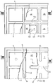
- the die for ceramic tiles comprises at least one semi-die 1, that is, the punch and/or buffer that may be inserted in a matrix M ( Figure 11), having an elastic membrane 2, anchored peripherally to the frame 3 of the semi-die 1, and having, on its external face, a surface 4 having the profile of one of the faces of tile to be formed, for example, the rear face, as shown.
- a matrix M Figure 11
- grooves 5, or indents can be provided to form the projections in the rear face of the tile, to enable it to be laid and/or transported during the various phases of the production cycle.
- the membrane 2 is coupled, in relation to its innermost face, with a floating forming plate 6 delimiting a chamber 7 in which an incompressible fluid, for example, pressurised oil, is introduced: the cavity 7 extends underneath the forming plate 6, up to its peripheral edge so that the incompressible fluid F contained in it may act uniformly substantially over the entire extent of the said plate.
- an incompressible fluid for example, pressurised oil
- the plate 6 is preferably inserted in cavity 7 in such a way as to occupy the entire surface of the tile to be pressed: that is, the said plate extends laterally up to the groove, or cavity, 5 destined to form the outermost rib or, respectively, appendage of the tile.
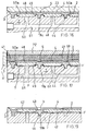
- the membrane 2 is anchored to the frame 3 of the semi-die 1 in such a way as to define a peripheral seal having a first lip 8 inserted in said cavity and provided with peripheral appendage 9 extending into a corresponding seat 10 to create a seal in a plane parallel to the plane in which the membrane 6 lies, so as to eliminate the risk of the incompressible fluid, for example, pressurised oil, escaping from the cavity during pressing with the detachment of the said first lip 8.
- the incompressible fluid for example, pressurised oil
- the membrane 2 is also provided with a second lip 9a, derived from the said first lip 8 in the opposite direction with respect to its appendage 9.
- the second lip 9a is wound round the peripheral edge of the forming plate 6 and possibly extends with a portion 11 under the said plate, as shown in Figures 1 and 2.
- the lip 8 extends, on the opposite side to that of the plate, so as to wind round a forming element 12, having an annular shape and preferably a circular transverse cross-section, and ending with its extremity 13 in a seat 14 beside the forming element 12.
- extremity 13 corresponds to appendage 9 already described with reference to the version of die as in Figure 1, but differs from it in that it is wound round forming element 12.
- the membrane 2 is also preferably provided with at least one intermediate elastic anchoring element 19, passing through a discontinuity, or opening, 22a in the forming plate 6 and anchored in a corresponding seat 20, advantageously with undercut, on the bottom of the cavity 7.
- seat 20 is made from a closed hole in the bottom of the cavity and has a base which is wider than its relative opening 20a.
- each intermediate elastic element 19 the walls of seat 20a are separated from the lateral surface of the relative element.
- the intermediate elastic element 19 also limits outward arching of the plate 6 when the cavity 7 is filled with incompressible fluid.
- the distribution of the intermediate traction elements 19 and the load carrying section of each of these have to be such as to generate on the plate 6 loads directed towards the bottom of the cavity 7 and to be of a magnitude that, when summed with the restraint distributed along the edge of the plate, they are substantially equivalent and opposed to the uniformly distributed load exerted by the pressure of the incompressible fluid, before pressing.
- the plate 6, and therefore the membrane 2 are maintained level, without altering the loading of the mixture of powders in the matrix of the die.
- the intermediate elastic traction element 19 can be provided with an intermediate annular projection 21, in the shape of a mushroom, firmly anchored to the plate 6 and inserted in a relative conjugate seat 22, made in the lower face of the plate 6 (Figure 3), or on the top face of the cavity 7 ( Figure 2): the function of the annular projection 21 is that of constituting a sealing element against oil leakage between the chamber 7 and the surface anchoring the membrane 2 to the plate 6 through the opening 22a.
- Each through opening 22a enables the formation of a corresponding elastic element 19 during vulcanisation of the membrane 2.
- membrane 2 is formed, with the relative elastic traction elements 19, by the action exerted on it, in a fluid or pasty state, by a vulcanising punch 23, whilst the conduit 7a is closed by a centering pin 24 for the plate 6.
- Figure 3 also shows 25, an elastic spacer element, for example a cylindrical helical compression spring, to facilitate the detachment of the plate 6 from the bottom of the cavity 7 after vulcanisation: the elastic element 25 is inserted in a seat 26 in the bottom of the cavity 7, advantageously positioned at the vertices of the said cavity, where the membrane is most likely to remain lying on the bottom of the cavity even after the cavity has been filled with incompressible fluid.
- an elastic spacer element for example a cylindrical helical compression spring
- the elastic traction elements 19 are distributed in oval, or elliptical, patterns shown with 27, 28: it being envisaged, for example, that the elastic elements 19 are positioned at the intersections between the directrix lines L, preferably passing through the centre C, such as the diagonals 29, 30 and/or median lines 31, 32 of the sides defining the bottom of the cavity and the said ellipses 27, 28.
- the distribution of the intermediate elastic elements 19 can be along circumferences 33, 34.
- the intermediate elastic elements 19 can have, for example, a slot-shaped cross-section 35.
- the membrane 2 can advantageously have, during the vulcanisation phase, projections 36 obtained with corresponding indentations in the forming punch, being shaped in such a way that, when the membrane is deformed as result of the insertion of the oil, its surface in contact with the tile to be pressed is substantially flat, that is, it does not have indentations caused by the pulling effect of the relative elastic element 19.
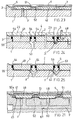
- the plate 39 has a number of openings 40, distributed in a chequered pattern, in which are inserted, during vulcanisation, the elastomer material constituting the membrane 2 and extending into the areas included between the grooves 5: in this way the membrane 2 and the plate 39 with its relative openings 40 together have a variable stiffness.
- the membrane 2 has areas with greater stiffness in the areas corresponding with the imprints 5, or grooves, or cavities for supporting the formed tile 41.
- the traction elements 19 of the membrane 2 towards the bottom of the cavity 7 can be situated in relation to the rigid parts of the said membrane, that is, in positions corresponding to those of the ribs 40a made in the floating plate 39, in this case being shown as 19a, as in the versions in Figures 12, 13, 14.
- the membrane 2 with the relative plate 39 has variable stiffness in the different areas of the tile, with the result that, where the tile is locally made up of a thinner or a thicker layer of powder than that which is theoretically envisaged, the membrane 2 and the plate 39 together deforms locally, in a corresponding manner, towards the tile 41 or towards the cavity 7.
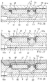
- the floating plate 42 can have openings in the shape of slots and communicating with elastic anchoring elements 19a inserted in corresponding seats having the same slot shape 44, or extending, as with 19c, from one side of the cavity 7 to the opposite side ( Figure 15, 16, 17).
- membrane 2 initially curved towards the powders to be pressed, is made to take on a substantially flat configuration by the thrust of the fluid F during pressing by the punch PZ with a tensile load on the elastic elements 19a, the final trim depending on the local density of the powders.
- the floating plate is made discontinuous by means of a formation of longitudinal and transverse openings that subdivide it into a plurality of tiles 48, for example, quadrangular, inserted so as to be floating in corresponding seats 49 ( Figure 16) into which the cavity 7 is subdivided:
- the tiles 48 can have any plan view shape, for example, polygonal with rounded vertices, for example, rectangular, or square, or circular, or whichever other convenient shape.
- the seats 49 are made communicating by means of channels 60 and 61 for the incompressible fluid: the form of the seats 49 preferably being flared upwards and in any case such as to enable the formation, during vulcanisation, of lips 50a in the membrane 2 wrapping round each tile 48 so as to incorporate it into the relative membrane.
- Figures 20, 21 show how in this version the membrane 2 is anchored to a plurality of anchoring elements 51 having a "T"-shaped cross-section, for anchoring the said membrane in undercut: these elements also being provided with transverse through holes 52 to further improve anchoring.
- T-shaped anchoring elements 51 as shown in Figures 20, 21, preferably provided with transverse through holes 52, can also be provided for the version of floating plate 42 in Figures 22, 23.
- the tiles 48 being of considerable thickness and having smooth lateral surfaces 53, are made to co-operate with sealing rings 54 intended to prevent, during vulcanisation, leakage of the elastomer material the membrane 2 is made of towards the underlying seats 55, the said seats constituting integral parts of the chamber 7 for the incompressible fluid; the sealing rings 55 being inserted in stepped grooves 56 in the side walls of the seats 55.
- the stepped grooves 57 for the said sealing rings can be made in the side walls of the tiles 48.
- the tiles 48 can be positioned so that they are in contact with the bottom of the corresponding cavity 55 or raised from it, for example with the positioning between them of a fluid material , for example, granular, such as sand S, that is expelled after forming.
- a fluid material for example, granular, such as sand S, that is expelled after forming.
- the sealing rings 54 in order to allow a greater flexibility and to improve sealing against oil leakage from cavity 7, can be inserted in stepped seats 56a having a diameter which is essentially greater than the external diameter of the corresponding sealing element 54.
- the membrane 2 can have a smooth external surface 59 ( Figure 26) during the vulcanisation phase with matrix 23, the grooves, or cavities, 5 being obtained with the deformation of the membrane only with the introduction of the pressurised fluid in the cavity 7.
- the seats 55 for the tiles 48 being an integral part of the cavity 7 in which the incompressible fluid F is contained, can be made intercommunicating by means of channel 62 which has an axis bent in the shape of a "V" to connect one seat directly with the one adjacent to it.
- the tiles 48 can have smooth lateral surfaces and can be inserted in seats 55 also having smooth lateral surfaces.
- Each tile 48 can be made to operate with, at its lower end, a collapsible support element 65 consisting of a central flat element 66, which has, axially, a hole 67 passing through it and, peripherally, a concave annular edge defining a seat for centering the relative tile 48.
- the position of the central hole 67 has to correspond to that of the hole 60 of the semi-die 1.
- the collapsible support 65 is pushed down to the bottom of the seat 55 and the tile 48 remains firmly in contact with the membrane 2: between the side walls of the tile 48 and the side walls of the seat 55 there is an annular joint 68 made of the material of the membrane 2 that favour the floating movements of each tile 48.
- the membrane 2 can be limited to the ensemble of annular joints 68, that is, the tiles do not have to be lined with the elastomer material on its active face in pressing.
- the collapsible support 65 can be in the shape of a saucer 69 ( Figure 35), or cup, possibly with a central hole to accommodate a sealing element 70 having the function of the tile 48, destined to be an integral part of the membrane 2.
- the sealing element can also consist of a sphere 71, as shown in the right-hand part of Figure 35.
- the surface of the collapsible support 65 facing the membrane 2 can advantageously be lined with a non adhesive substance in order to prevent the undesirable adhesion between the said element and the membrane during vulcanisation.
- Figure 50 also shows a temporary collapsible support having a flat shape, for example, a ring 72, positioned, with overhang, in a stepped seat 73 in the alveolus, or seat 55.
- This particular type of temporary support element is preferable for its simplicity, in that it enables the use of commercially available rings, or washers, with a considerable saving in cost.
- the ring 72 can be deformed down towards the bottom of the cavity 55 with a preliminary pressing stroke by punch P: to make such a deformation possible the width D1 of each tile 48 is preferably less than the minimum width D2 of the relative seat 55.
- Figure 51 shows how the tiles 48a can even emerge at the pressing surface, in which case there are interruptions in corresponding parts of the membrane 2: the tiles 48a are each individually connected to a seat 55 by means respective annular joints 68.
- the die 1 can have a frame 3, with sloping peripheral portion 3a and horizontal positioning portion 104 corresponding to a first external row 105 (Figure 39) of support ribs of the tile, in bas-relief; 106, the alveoli of the buffer plate, delimited by ribs, or walls, 107 and bottom 107a; 108, opposing overlapping incisions made in either side of the base of each wall 107 to make each alveolus 106 intercommunicating, made, for example, using a radial milling cutter 109; 108a, a peripheral groove made in the middle-upper part of the alveolus to improve the anchorage of the elastic membrane; 110, ( Figure 37) an inlet conduit for the fluid at the bottom of the alveoli 106; 111, ( Figure 38) tablets made of a soluble and/or retractable or meltable material - for example, a low density expanded material such as expanded polystyrene of approximately 110 gr/dm3 - each inserted
- the elastic membrane is formed in the following way: once the buffer has been sandblasted to degrease it and to make it more suitable for retaining the used for anchoring the said membrane to the surfaces of the buffer and to the relative surfaces of the alveoli, the tablets 111 are inserted, advantageously together with the covering metal sheet 117, 118, which have to enter into the alveolus 106 with a clearance of the order of hundredths of a millimetre; the sandblasting is possibly repeated and the adhesive substance is applied, for example, by spraying, to the surfaces that are to come into contact with the said membrane, including the surface of the metal sheet; one the buffer is preheated to about 100-125 °C, the elastic forming substance of the membrane 2 is cast, for example, a polymer such as CYANAPRENE (manufactured by the company AIR PRODUCTS, Allentown, USA); having positioned a layer of non adhesive substance between the matrix 23 and the membrane 2, after approximately 5 minutes, required for reticulation, the die is
- the tablet 111 can have the function of collapsible support for the tile 48 positioned above it; with a deforming stroke of the punch P, the tablet 111a takes on a flattened configuration on the bottom 107a of each alveolus.
- the tablet can consist of clay, or slats (for example, sodium bicarbonate), or other substance or compound that is soluble, or miscible, in water.
- Figure 52 shows a collapsible support 111a made of expanded polystyrene positioned between the bottom of the cavity 7, in such a way as occupy it completely, and the innermost face of a plate 42.
- the plate is kept in position by the support element, or tablet, 111a, whereupon it is subsequently reduced, as described previously.
- the collapsible support element can also consist of a panel 90 (Figure 53) of composite material, comprising a pair of outer layers 91 between which is placed a reducible layer 92, for example, made of a corrugated metallic material.
- the reduction of the element 90 can be achieved by flattening it against the bottom of the cavity 7, or of the alveoli 55.
- the membrane 2, for example, that wraps around the plate 6, 48 can also consist of various polymer materials, for example, of a material with a high degree of elasticity for the anchorage areas 6, 68, 19, 19a, and of a stiffer material for the face of the plate 5, 48 facing the powders to be pressed.
Landscapes
- Engineering & Computer Science (AREA)
- Mechanical Engineering (AREA)
- Physics & Mathematics (AREA)
- Fluid Mechanics (AREA)
- Manufacturing & Machinery (AREA)
- Chemical & Material Sciences (AREA)
- Ceramic Engineering (AREA)
- Press-Shaping Or Shaping Using Conveyers (AREA)
- Compositions Of Oxide Ceramics (AREA)
Abstract
Description
- The invention concerns a die for pressing ceramic tiles and a relative manufacturing method.
- The prior art comprises Italian patent for industrial invention IT-B-1104511 in which the ceramic tiles are pressed under the action of an elastic modelling membrane, for example, made of rubber, delimiting a chamber in a relative semi-die in which an incompressible fluid, for example, oil, is introduced; by means of such a die it is possible to make the density of the pressed tiles homogeneous so as to limit undesired dimensional variations during their subsequent firing.
- The same patent also proposes the use of stiffer plates applied to the external surface of the elastic modelling membrane with a view to limiting excessive deformation in the membrane.
- This patent: however, whilst introducing the fundamental concept of homogeneous pressing of ceramic tiles, has been found to be subject to a tendency towards a non uniform thickness of the pressed items.
- With a view to obtaining a substantially uniform thickness, at least in the areas of the supports of the tile, the adoption of a grill, or lattice, has been proposed, for example, in the European patent application EP-B-0556163, occupying the cavity in which the incompressible fluid is placed, and which is rigidly fixed to the bottom of the said cavity, in order to enable the elastic membrane to be anchored to it at least in the areas destined to form the support appendages on the base of the tile.
- However, having anchored the membrane to a fixed grill prevents, in the anchorage areas, the possibility of the displacement of the membrane that is necessary in order to achieve homogenous pressing, thereby giving rise to variations in the density of the pressed tile which cause, on the opposite face, an aesthetically unpleasant motif corresponding to the underlying grill.
- In particular, if, in an area of the matrix, the level of the loaded powders, or their density, is less than the predetermined amount, the areas corresponding to the support ribbing of the tile are not as well pressed and consequently the corresponding areas on the opposite face have a greater porosity, with an unacceptable variation in the surface finish and a considerable reduction, in these areas, in the mechanical strength of the support.
- The visibility of the lattice where the elastic membrane is anchored to the underlying grill is due, in particular, to the manner in which the elastic membrane deforms, that is, with bulging surfaces, substantially spherical, with considerable lack of homogeneity of pressing between the areas of the membrane close to the grill and the central areas further from the said grill.
- On the other hand, in the case whereby, locally, the level of the powders loaded in the matrix is greater than the predetermined amount, bulging can occur between one rib and the next on the reverse side of the tile, the size of the bulge being such as to protrude beyond the theoretical support plane of the tile as defined by the extremities of the ribs, or support appendages in general: this gives rise to corresponding surface defects of the top face of the support during firing, also making it difficult to transfer the tiles along the motorised roller conveyor lines.
- Utility model IT-U-214739 proposes a die for ceramic tiles in which the body of a punch has a plurality of intercommunicating seats, filled with oil or other incompressible fluid, in which are inserted, with wet seal, pistons sliding in them in order to impart differentiated degree of compaction in the various zones of the mass of powders during pressing. Between the active ends of the said pistons and the powders to be pressed there being an elastically deformable membrane acting as a coating for the surface of the punch.
- However, such a die requires a high degree of precision in machining the seats and the relative pistons, and as a result, is very expensive.
- Furthermore, with such a die, there is the risk that, during operation, an certain amount of oil may get past the seals placed between the said pistons and the relative seats and infiltrate between the active faces of the said pistons and the portion of membrane facing it: this causes the formation of pools of liquid which set up permanent deformations in the membrane and defects in the pressed tiles.
- It is also to be noted that the areas of the membrane that interact with the edges of the underlying pistons are subject to high loads that can rapidly cause the said membrane to rupture.
- Finally, during pressing, the powders exert a high pressure on the membrane which tends to cause the membrane to extrude between the radial gap between the piston and the relative seat: this produces a progressive blocking of the pistons in their relative seats with, consequently, a loss of mobility of the pistons.
- The prior art also comprises a die described in the patent application IT-A-MO93A000068 in which the elastic membrane, on the side opposite to that in contact with the powders for forming the tile, is equipped with appendages, for example, each consisting of a cover made of an elastic material, preformed and cooperating with the walls of the alveolus to which the said cover is attached and on whose base its lower rim rests: during the operation of vulcanisation the said elastic cover forms an integral part of the said membrane, closing off the alveolus and so enabling the chamber for the incompressible fluid to remain free, delimited by the internal surface of the same cover.
- However, given that the lower rim of the cover has to rest on the base of the relative alveolus, the corresponding part of the surface of the said cover can not be subjected to the pressure of the incompressible fluid, with loss, therefore, of active surface as regards the homogenising action of the membrane on the powders being formed.
- Such prior art may be subject to considerable improvements with a view to eliminating the said drawbacks.
- From the foregoing emerges the need to resolve the technical problem of inventing an isobaric die for ceramic tiles in which it is possible to obtain a homogeneous degree of pressing whilst avoiding the generation of surface defects in the pressed items and maintaining a substantially constant thickness.
- A further aspect of the technical problem is that of inventing an isobaric die for pressing substantially flat items, in particular, ceramic tiles, in which it is possible to maintain a substantially flat configuration of the plate and of the part of the membrane associated with it prior to pressing, in particular during the loading phase of the powders in the matrix of the relative semi-die; this in a simple and economical manner.
- A further aspect of the technical problem is that of inventing a method for the manufacture of isobaric dies that enables the elimination of all loss of active surface in the chambers defined by the alveoli that contain the incompressible fluid.
- Another aspect of the same technical problem being that of reducing the manufacturing costs of the isobaric dies.
- The invention resolves the said technical problem by adopting an isostatic die for pressing tiles, comprising a semi-die having a plate delimiting a cavity in the semi-die containing the incompressible fluid and anchored to the said semi-die by means of an elastic sealing element for the incompressible fluid in the said cavity, the said plate being free to perform limited displacements closer to, or further away from, the base of the said cavity, characterised in that the said plate has openings passing through it.
- The elastic element can consist of an elastic membrane anchored to the body of the semi-die along its edge and to the surface of the plate facing the powders to be pressed.
- Alternatively, the elastic element can be anchored along the edge of the said plate to the body of the semi-die so as to constitute an elastic hinge joint.
- The areas of discontinuity in the plate can consist of a regular formation of through holes made in the body of the said plate, or of a formation of incisions that subdivide the plate into a plurality of independent tiles, or of a formation of independent slots, for example, aligned and offset in mutually perpendicular directions.
- This affords the particular advantage of obtaining uniform pressing whilst maintaining a substantially homogeneous thickness of the tile, due to the discontinuities in the plate acting in a differentiated manner on the various areas of the surface of the membrane in function of the loads transmitted locally by the powders during pressing.
- Furthermore, the presence of discontinuities in the plate, particularly in the version of plate subdivided into independent tiles, determines displacements of the membrane only in planes substantially parallel to the forming plane: this achieves, with a given displacement of the tiles, the compaction of a greater volume of powder than is possible with a membrane that deforms in curved configurations; conversely, with a given volume of powder displaced in compensating for the non homogeneous loading of the matrix of the die, the displacement of the tiles in planes parallel to the forming planes is much less than that which would be required with curved deformations of the membrane.
- Furthermore, the displacements of the tiles in planes parallel to the forming plane afford a better compensation of pressing, also in the areas close to the ribbing, or appendages, where significant lack of homogeneity can be found when using prior art dies.
- Furthermore, the adoption of areas of discontinuity in the plate consisting of a regular formation of openings, arranged as in a chequred pattern, enables the compensation during pressing of the non homogeneous loading of the matrix of areas a considerable distance apart as a result of the elastic deformation of the plate. On the other hand, the compensation between areas a short distance apart is obtained with the elastic deformation of the membrane in the areas of discontinuity in the plate. This enables local deformations of the membrane to be limited, thereby also limiting the structural defects of the pressed item.
- In a further advantageous version, the areas of discontinuity in the plate are made cooperating with at least one appendage, or tie, or elastic anchoring element, fashioned in the surface of the membrane on the side facing the cavity and anchored in a corresponding seat fashioned in the base of the said cavity.
- The said appendage, or tie, or elastic anchoring element, is advantageously made up of the same material as the membrane and is integral with it, in such a way that it passes through the said plate.
- This affords the advantage of enabling the plate to be maintained level independently of the pressure of the incompressible fluid inside the chambers during loading, with consequently a considerable reduction in the defects during the loading of the powders in the matrix of the die and in the subsequent pressing.
- In a further advantageous version, there are a plurality of intermediate elastic anchorage elements, distributed in a configuration, for example, defined by concentric ideal circumferences, or ellipses.
- Advantageously, it is also envisaged that the intermediate elastic anchorage elements can be offset with respect to the cavities set into the face of the membrane in contact with the powders to be pressed for the formation of the supporting elements of the pressed tile, or for their anchoring when they are laid.
- This, so as not to alter the alignment of the cavities destined to form the support appendages during forming.
- It is also envisaged that the intermediate elastic anchorage elements can be distributed in relation to ribs obtained in the floating plate, as defined by the formation of through openings made in the said plate: the cavities of the membrane destined to form the support appendages of the tile being positioned in relation to the said ribs.
- This enables the adoption of a forming method comprising the loading of the matrix of a semi-die having an elastic membrane associated with a plate inserted in a cavity destined to contain the incompressible fluid, for the subsequent pressing of the said powders; it being envisaged that the said incompressible fluid be contained in the cavity of the said semi-die and acts on the said floating plate to lift it during pressing so as to maintain the ratio between the maximum and minimum thickness of the powders unaltered, both during the loading of the powders and during the pressing: this without introducing, or extracting, quantities of the said incompressible fluid from the said matrix.
- According to a further aspect of the invention, a method is envisaged for the manufacture of an isobaric die for pressing ceramic tiles, having a plate delimiting a cavity of the semi-die in which is contained an incompressible fluid and anchored to the said semi-die by means of an elastic sealing element for the incompressible fluid in the said cavity, the said plate being free to perform limited displacements closer to, or further away from, the base of the said cavity, the method comprising the vulcanisation in situ of the said elastic element and the subsequent filling of the said cavity with the said incompressible fluid, characterised in that, prior to the said vulcanisation, a temporary support element, functionally reducible, having a profile matching that of the plan shape of the cavity, is inserted into the said cavity and that, after the said vulcanisation and before the said filling, the temporary support element is reduced.
- The cavity, occupying the entire extension of the active surface of the die, can be divided into a plurality of alveoli in which sit the singular portions, or tiles, into which the plate is subdivided.
- The said temporary support element, or tablet, can be made of a material which is soluble, and/or which may be shrunk, or collapsed, or dissolved, or incinerated using heat.
- The reduction of the said temporary support element can be achieved physically, or chemically.
- The temporary support element can have a thickness constituting a fraction of the depth of the alveolus, up to 50% or more.
- The reduction of the said temporary support element, or tablet, possibly being achieved by means of inserting into the said alveoli a solvent of the material the temporary support element, or tablet, is made of.
- Alternatively the reduction can be achieved with the mechanical reduction of the volume, or flattening, of the support element against the bottom of the alveolus.
- Furthermore, the said reduction can be achieved by melting.
- In an example of embodiment, referring to the version of die with cavity subdivided into alveoli, the material of the said tablet is expanded polystyrene, with a density of less than 150 kg/m3, conveniently 110 kg/m3 or even much less (down to approximately 60) in that it is more easily dissolved and disgregated.
- The reduction can be achieved chemically by introducing methyl chloride, or trichloroethylene, into the alveoli, after vulcanisation, through the hole used for the introduction of the incompressible fluid, letting it circulate for a few minutes then removing it through the hole used for the outlet of the incompressible fluid: in this way the chambers of the alveoli are freed for the subsequent introduction into them of the said fluid.
- Alternatively, the reduction of the tablets can be achieved physically (with volume reduction) by introducing, after the vulcanisation when the die is still in the forming press of the membrane, a suitable compressed gas, at a pressure of at least a few dozen bar, through the same hole, so as also to flatten the said tablet.
- Increasing the pressure is advantageously associated with an increase in the temperature of the compressed gas, up to the melting point of expanded polystyrene, whereupon the melted residue is possibly evacuated.
- The thickness of the tablet may vary from approximately 1 to approximately 5 mm, with a depth of alveolus of between 8 and 10 mm.
- Moreover, the choice of the soluble material for the tablet of the expanded polystyrene type, requires that the top surface of the said tablet be protected with a layer of substance resistant to the solvents contained in the adhesives used in the vulcanisation of the membrane, for example, conveniently, by means of a thin metal sheet having points folded back to mount the tablet to it and to make it more easily introduced into the alveolus together with the said plate.
- Above the said protective layer there being, in the walls of each alveolus, a peripheral groove that constitutes an undercut so as to obtain further and advantageous anchorage of the appendages of the elastic membrane that penetrated into the alveolus during the vulcanisation.
- The casting of the elastic membrane, for example made of the material "CYANAPRENE", is followed, after approximately 5 minutes required for reticulation, with the closure of the die with a pressure of a few bar and heating to a temperature of almost 100 °C even up to 125 °C or more for approximately 10 minutes; seasoning at approximately 80 °C and cooling then follows.
- The advantages obtained with the method of the present invention are: exploitation, in terms of contact between the incompressible fluid and the membrane, of the entire section of the alveolus.
- Precise delimitation of the chamber of incompressible fluid in each alveolus during the vulcanisation phase of the elastic membrane.
- Reduction in cost in relation to the substitution of the rubber cover with a tablet that may be dissolved or melted, with removable or insignificant residue, protected from the action of the solvents contained in the adhesive substance applied prior to the casting for the vulcanisation.
- Increased anchorage of the elastic membrane with respect to that which may be obtained with just the adhesive substance, due to the adoption of the peripheral groove in the walls of the alveolus.
- Further characteristics and advantages of the die and of the method as described will emerge from the following description, purely by way of example, of some embodiments illustrated in the eighteen tables of drawings attached in which:
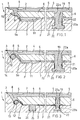
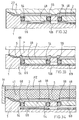
- Figure 1 is a partial and interrupted transverse section of an isobaric die in a first version with discontinuity elements in the plate having anchoring elements for the membrane at the bottom of the cavity;
- Figure 2 is a section as in Figure 1, but in a variant of the peripheral anchorage of the membrane and of the coupling of the anchoring element to the bottom of the cavity;
- Figure 3 is a section as in Figure 1, but in a further version of the anchorage of the membrane along its peripheral edge.
- Figure 4 is a section as in Figure 2, but in a further variant of the peripheral anchorage of the membrane, showing a distancing elastic element of the membrane;
- Figure 5 is a section as in Figure 4, but during the forming of the elastic membrane by vulcanisation;
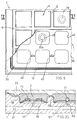
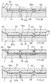
- Figure 6 is a schematic top view of the bottom of a cavity of the semi-die as described, showing the distribution of the elastic anchoring elements on concentric ellipses, for the production of rectangular tiles;
- Figure 7 is a schematic view as in Figure 6, but with the distribution on concentric circumferences for pressing square tiles;
- Figure 8 is a schematic view as in Figure 7, but elastic elements having differing transverse cross sections for pressing polygonal tiles, for example, hexagonal;
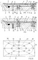
- Figure 9 is a partial and partially sectioned plan view of a die as described, in a version with discontinuous plate having a regular formation of openings distributed in a chequered pattern;
- Figure 10 is section X-X, partial, interrupted and enlarged, of Figure 9;
- Figure 11 is a vertical section of a die as described, in the version as in Figure 10, in pressing configuration;
- Figure 12 is a section as in Figure 10, but in a version of die with traction elements distributed in the areas corresponding to the rigid parts of the membrane to obtain the controlled loading of the powders in the matrix, in the configuration relating to the vulcanisation of the membrane;
- Figure 13 is a section as in Figure 12, but during the loading phase of the powders in the matrix;
- Figure 14 is a section as in Figure 12, but during the pressing phase of the tile;
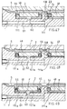
- Figure 15 is a partially sectioned and interrupted front view of a die as described, but in a version with plate subdivided in a plurality of tiles;
- Figure 16 is section XVI-XVI of Figure 15, but during the vulcanisation;
- Figure 17 is a section as in Figure 16, but during the pressing;
- Figure 18 is an interrupted and partially sectioned front view of a die as described, but in a version with stiffening plate having slot-shaped openings;
- Figure 19 is section XIX-XIX of Figure 18;
- Figure 20 is a partial and interrupted plan view analogous to that of Figure 15 but with anchoring elements for the membrane having "T"-shaped sections.
- Figure 21 is section XXI-XXI of Figure 20, during pressing;
- Figure 22 is a view as in Figure 18, but relating to a variant with anchoring elements for the membrane having "T"-shaped sections;
- Figure 23 is section XXIII-XXIII, deviated, of Figure 22;
- Figure 24 is a partial and interrupted vertical section of an isobaric die as described, but in a version with forming plate subdivided into tiles each inserted in a seat in the relative semi-die, during the vulcanisation phase;
- Figure 25 is a section as in Figure 24, but in the phase prior to pressing;
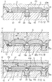
- Figure 26 is a section as in Figure 24, but in a further version with stepped seats for housing sealing rings co-operating with the tiles of the plate: it also shows a variant of the die with tiles emerging at the pressing surface;
- Figure 27 is a section as in Figure 26, but with cavities, or grooves, for the formation of support ribbing, or appendages, of the tile;
- Figure 28 is a section of the die as in Figures 26, 27, but during the pressing phase;
- Figure 29 is a section as in Figure 21, but in a version in which the tiles, during vulcanisation, are supported on and centred by a collapsible supporting element;
- Figure 30 is a section as in Figure 29, but at the end of the permanent deformation stroke of the collapsible supporting elements;
- Figure 31 is a section as in Figure 29, but relating to the buffer during operation;
- Figure 32 is a section as in Figure 29, but each supporting element for the tile being collapsible and in the shape of a saucer;
- Figure 33 is a section as in Figure 32, but at the end of the deformation stroke of the collapsible supports;
- Figure 34 is a section as in Figure 29, but relating to the die during operation;
- Figure 35 is a section as in Figure 29, but relating to variants of the collapsible support with the tile being centred on the internal edge of the said element and, respectively, with sealing sphere;
- Figure 36 is a partial plan view of the active face of the buffer of the die, during the machining of the alveoli;
- Figure 37 is vertical section XXXVII-XXXVII of Figure 36;
- Figure 38 is a partial vertical section of the same part of the die, but after the insertion in the alveoli, from above, of the dissolvable tablets with a protective layer on them;
- Figure 39 is a section as in Figure 38, but with superposition, on the above mentioned part of the die, of the matrix for vulcanising the elastic membrane;
- Figure 40 is analogous to Figure 39, showing the phase in which the tablets are dissolved;
- Figure 41 is analogous to Figure 40, but in the case of the reduction of the volume of the said tablets;
- Figure 42 is a plan view a pressed metal sheet constituting a possible embodiment of the protective layer of the tablet;,
- Figure 43 is a perspective view of such a pressed metal sheet readied for the insertion into it of the tablet, but in an up side down position;
- Figure 44 is a perspective view of a preferred parallelepiped shape of the tablet, with rounded vertical corners;
- Figure 45 is a perspective view of such a tablet inserted in the metal sheet for the their insertion together in one of the alveoli;
- Figure 46 is a section of a die as in Figure 38, with the tablet and metal sheet inserted;
- Figure 47 is a section as in Figure 29, but with the tiles supported by the said tablet during the vulcanisation: it shows how the tiles can be associated with sealing rings each one of which is also supported by the same tablet relative to the tile to which the relative ring is associated;
- Figure 48 is a section as in Figure 47, but at the end of the permanent deformation stroke of the collapsible support elements;
- Figure 49 is a section as in Figure 47, nut relating to the die during operation;
- Figure 50 is a vertical, interrupted section of a die as described, with collapsible temporary support element being annular in form;
- Figure 51 is a section as in Figures 29, 31, but with tiles emerging at the pressing surface;
- Figure 52 is a vertical section of a die as described, but in a version with plate having slot-shaped openings in association with a temporary support element in polystyrene;
- Figure 53 is an interrupted perspective view of a collapsible support element consisting of a composite plate with an undulated internal layer.
- The die for ceramic tiles comprises at least one
semi-die 1, that is, the punch and/or buffer that may be inserted in a matrix M (Figure 11), having anelastic membrane 2, anchored peripherally to theframe 3 of thesemi-die 1, and having, on its external face, asurface 4 having the profile of one of the faces of tile to be formed, for example, the rear face, as shown. - In this
case grooves 5, or indents, can be provided to form the projections in the rear face of the tile, to enable it to be laid and/or transported during the various phases of the production cycle. - The
membrane 2 is coupled, in relation to its innermost face, with a floating formingplate 6 delimiting achamber 7 in which an incompressible fluid, for example, pressurised oil, is introduced: thecavity 7 extends underneath the formingplate 6, up to its peripheral edge so that the incompressible fluid F contained in it may act uniformly substantially over the entire extent of the said plate. - The
plate 6 is preferably inserted incavity 7 in such a way as to occupy the entire surface of the tile to be pressed: that is, the said plate extends laterally up to the groove, or cavity, 5 destined to form the outermost rib or, respectively, appendage of the tile. - The
membrane 2 is anchored to theframe 3 of thesemi-die 1 in such a way as to define a peripheral seal having afirst lip 8 inserted in said cavity and provided with peripheral appendage 9 extending into acorresponding seat 10 to create a seal in a plane parallel to the plane in which themembrane 6 lies, so as to eliminate the risk of the incompressible fluid, for example, pressurised oil, escaping from the cavity during pressing with the detachment of the saidfirst lip 8. - As regards this point, it is to be noted that during operation appendage 9 and the relative
first lip 8 are subjected prevalently to compressive loads. - Furthermore, the thrust generated by the fluid during pressing tends to push the appendage 9 against its
seat 10, so favouring its sealing action. - The
membrane 2 is also provided with asecond lip 9a, derived from the saidfirst lip 8 in the opposite direction with respect to its appendage 9. - The
second lip 9a is wound round the peripheral edge of the formingplate 6 and possibly extends with aportion 11 under the said plate, as shown in Figures 1 and 2. - In particular, in the version as in Figure 2, the
lip 8 extends, on the opposite side to that of the plate, so as to wind round a formingelement 12, having an annular shape and preferably a circular transverse cross-section, and ending with itsextremity 13 in aseat 14 beside the formingelement 12. - In practice,
extremity 13 corresponds to appendage 9 already described with reference to the version of die as in Figure 1, but differs from it in that it is wound round formingelement 12. - The
membrane 2 is also preferably provided with at least one intermediateelastic anchoring element 19, passing through a discontinuity, or opening, 22a in the formingplate 6 and anchored in acorresponding seat 20, advantageously with undercut, on the bottom of thecavity 7. - To this end,
seat 20 is made from a closed hole in the bottom of the cavity and has a base which is wider than itsrelative opening 20a. - Furthermore, in order to improve the elasticity of each intermediate
elastic element 19, the walls ofseat 20a are separated from the lateral surface of the relative element. - The elastic
intermediate element 19, advantageously made of the same material themembrane 2 is made of and being an integral part of it, is vulcanised together with the said membrane, as shown in Figure 5, so as to constitute a traction element for theplate 6 towards the bottom of thecavity 7 when the incompressible fluid is introduced into it, through arelative inlet conduit 7a. - The intermediate
elastic element 19 also limits outward arching of theplate 6 when thecavity 7 is filled with incompressible fluid. - The distribution of the
intermediate traction elements 19 and the load carrying section of each of these have to be such as to generate on theplate 6 loads directed towards the bottom of thecavity 7 and to be of a magnitude that, when summed with the restraint distributed along the edge of the plate, they are substantially equivalent and opposed to the uniformly distributed load exerted by the pressure of the incompressible fluid, before pressing. - In this way, independently of how much the
cavity 7 is filled, theplate 6, and therefore themembrane 2, are maintained level, without altering the loading of the mixture of powders in the matrix of the die. - The intermediate
elastic traction element 19 can be provided with an intermediateannular projection 21, in the shape of a mushroom, firmly anchored to theplate 6 and inserted in a relativeconjugate seat 22, made in the lower face of the plate 6 (Figure 3), or on the top face of the cavity 7 (Figure 2): the function of theannular projection 21 is that of constituting a sealing element against oil leakage between thechamber 7 and the surface anchoring themembrane 2 to theplate 6 through theopening 22a. - Each through
opening 22a enables the formation of a correspondingelastic element 19 during vulcanisation of themembrane 2. - During the vulcanisation phase (Figure 5)
membrane 2 is formed, with the relativeelastic traction elements 19, by the action exerted on it, in a fluid or pasty state, by a vulcanisingpunch 23, whilst theconduit 7a is closed by a centeringpin 24 for theplate 6. - Figure 3 also shows 25, an elastic spacer element, for example a cylindrical helical compression spring, to facilitate the detachment of the
plate 6 from the bottom of thecavity 7 after vulcanisation: theelastic element 25 is inserted in aseat 26 in the bottom of thecavity 7, advantageously positioned at the vertices of the said cavity, where the membrane is most likely to remain lying on the bottom of the cavity even after the cavity has been filled with incompressible fluid. - As shown in the version of Figure 6, the
elastic traction elements 19 are distributed in oval, or elliptical, patterns shown with 27, 28: it being envisaged, for example, that theelastic elements 19 are positioned at the intersections between the directrix lines L, preferably passing through the centre C, such as thediagonals median lines ellipses - Instead of the
ellipses elastic elements 19 can be alongcircumferences - The intermediate
elastic elements 19 can have, for example, a slot-shapedcross-section 35. - It is to be noted that at the
elastic elements 19 themembrane 2 can advantageously have, during the vulcanisation phase,projections 36
obtained with corresponding indentations in the forming punch, being shaped in such a way that, when the membrane is deformed as result of the insertion of the oil, its surface in contact with the tile to be pressed is substantially flat, that is, it does not have indentations caused by the pulling effect of the relativeelastic element 19. - In a further version shown in Figure 9, the
plate 39 has a number ofopenings 40, distributed in a chequered pattern, in which are inserted, during vulcanisation, the elastomer material constituting themembrane 2 and extending into the areas included between the grooves 5: in this way themembrane 2 and theplate 39 with itsrelative openings 40 together have a variable stiffness. - In particular, the
membrane 2 has areas with greater stiffness in the areas corresponding with theimprints 5, or grooves, or cavities for supporting the formedtile 41. - It is to be noted that the
traction elements 19 of themembrane 2 towards the bottom of thecavity 7 can be situated in relation to the rigid parts of the said membrane, that is, in positions corresponding to those of theribs 40a made in the floatingplate 39, in this case being shown as 19a, as in the versions in Figures 12, 13, 14. - As shown in Figures 11, 13, 14, the
membrane 2 with therelative plate 39, has variable stiffness in the different areas of the tile, with the result that, where the tile is locally made up of a thinner or a thicker layer of powder than that which is theoretically envisaged, themembrane 2 and theplate 39 together deforms locally, in a corresponding manner, towards thetile 41 or towards thecavity 7. - In a further version (Figures 18, 19, 22, 23) the floating
plate 42 can have openings in the shape of slots and communicating withelastic anchoring elements 19a inserted in corresponding seats having thesame slot shape 44, or extending, as with 19c, from one side of thecavity 7 to the opposite side (Figure 15, 16, 17). - In the versions as in the preceding Figures 13, 14, it is possible to vary the thickness of the layer of powders when loading the matrix of the die so as to maintain a constant ratio between the maximum and minimum thickness A1 and B1 of the soft tile and the maximum and minimum thickness A2 and B2 of the pressed tile.
- This is obtained completely automatically, that is, without the need to add or subtract incompressible fluid from the cavity 7: in fact, during pressing,
membrane 2, initially curved towards the powders to be pressed, is made to take on a substantially flat configuration by the thrust of the fluid F during pressing by the punch PZ with a tensile load on theelastic elements 19a, the final trim depending on the local density of the powders. - In a further version, shown in Figure 15, the floating plate is made discontinuous by means of a formation of longitudinal and transverse openings that subdivide it into a plurality of
tiles 48, for example, quadrangular, inserted so as to be floating in corresponding seats 49 (Figure 16) into which thecavity 7 is subdivided: thetiles 48 can have any plan view shape, for example, polygonal with rounded vertices, for example, rectangular, or square, or circular, or whichever other convenient shape. - The
seats 49 are made communicating by means ofchannels seats 49 preferably being flared upwards and in any case such as to enable the formation, during vulcanisation, oflips 50a in themembrane 2 wrapping round eachtile 48 so as to incorporate it into the relative membrane. - It is to be noted, also, that in the versions in Figures 15 to 19, the presence of the
anchorage appendages 19 gives the membrane further possibility of adjusting its trim in equilibrium with the incompressible fluid when the pressing load is applied, in such a way as to guarantee an isostatic pressing also in the areas corresponding to the supports of the tiles. - Figures 20, 21 show how in this version the
membrane 2 is anchored to a plurality of anchoringelements 51 having a "T"-shaped cross-section, for anchoring the said membrane in undercut: these elements also being provided with transverse throughholes 52 to further improve anchoring. - "T"-shaped
anchoring elements 51, as shown in Figures 20, 21, preferably provided with transverse throughholes 52, can also be provided for the version of floatingplate 42 in Figures 22, 23. - In Figures 24, 25, the
tiles 48, being of considerable thickness and having smoothlateral surfaces 53, are made to co-operate with sealingrings 54 intended to prevent, during vulcanisation, leakage of the elastomer material themembrane 2 is made of towards the underlyingseats 55, the said seats constituting integral parts of thechamber 7 for the incompressible fluid; the sealing rings 55 being inserted in steppedgrooves 56 in the side walls of theseats 55. - On the other hand, should it be preferable to have smooth side walls for the
seats 55, the stepped grooves 57 for the said sealing rings can be made in the side walls of thetiles 48. - During forming, the
tiles 48 can be positioned so that they are in contact with the bottom of the correspondingcavity 55 or raised from it, for example with the positioning between them of a fluid material , for example, granular, such as sand S, that is expelled after forming. - In this way it is possible to assign the tiles a maximum predetermined stroke H during pressing, with an amplitude advantageously less than the depth R of the grooves, or cavities, 5 so as to guarantee the formation of ribs or, respectively, support appendages for the tile in all working conditions.
- In the versions shown in Figures 26, 27, 28, the sealing rings 54, in order to allow a greater flexibility and to improve sealing against oil leakage from
cavity 7, can be inserted in steppedseats 56a having a diameter which is essentially greater than the external diameter of the corresponding sealingelement 54. - It is to be noted that the
membrane 2 can have a smooth external surface 59 (Figure 26) during the vulcanisation phase withmatrix 23, the grooves, or cavities, 5 being obtained with the deformation of the membrane only with the introduction of the pressurised fluid in thecavity 7. - The
seats 55 for thetiles 48, being an integral part of thecavity 7 in which the incompressible fluid F is contained, can be made intercommunicating by means ofchannel 62 which has an axis bent in the shape of a "V" to connect one seat directly with the one adjacent to it. - In the version shown in Figures 29 to 35, the
tiles 48 can have smooth lateral surfaces and can be inserted inseats 55 also having smooth lateral surfaces. - Each
tile 48 can be made to operate with, at its lower end, acollapsible support element 65 consisting of a centralflat element 66, which has, axially, ahole 67 passing through it and, peripherally, a concave annular edge defining a seat for centering therelative tile 48. - The position of the
central hole 67 has to correspond to that of thehole 60 of thesemi-die 1. - When the elastomer material that the
membrane 2 is made of is acted on by the punch P comprising an elastic active surface, or an active surface with appendages protruding in areas corresponding to those of thetiles 48, thecollapsible support 65 is pushed down to the bottom of theseat 55 and thetile 48 remains firmly in contact with the membrane 2: between the side walls of thetile 48 and the side walls of theseat 55 there is an annular joint 68 made of the material of themembrane 2 that favour the floating movements of eachtile 48. - In this case, the
membrane 2 can be limited to the ensemble ofannular joints 68, that is, the tiles do not have to be lined with the elastomer material on its active face in pressing. - The
collapsible support 65 can be in the shape of a saucer 69 (Figure 35), or cup, possibly with a central hole to accommodate a sealingelement 70 having the function of thetile 48, destined to be an integral part of themembrane 2. The sealing element can also consist of asphere 71, as shown in the right-hand part of Figure 35. - The surface of the
collapsible support 65 facing themembrane 2 can advantageously be lined with a non adhesive substance in order to prevent the undesirable adhesion between the said element and the membrane during vulcanisation. - Figure 50 also shows a temporary collapsible support having a flat shape, for example, a
ring 72, positioned, with overhang, in a steppedseat 73 in the alveolus, orseat 55. This particular type of temporary support element is preferable for its simplicity, in that it enables the use of commercially available rings, or washers, with a considerable saving in cost. - After vulcanisation, the
ring 72 can be deformed down towards the bottom of thecavity 55 with a preliminary pressing stroke by punch P: to make such a deformation possible the width D1 of eachtile 48 is preferably less than the minimum width D2 of therelative seat 55. - Figure 51 shows how the
tiles 48a can even emerge at the pressing surface, in which case there are interruptions in corresponding parts of the membrane 2: thetiles 48a are each individually connected to aseat 55 by means respectiveannular joints 68. - As shown if Figure 36, the die 1 can have a frame 3, with sloping peripheral portion 3a and horizontal positioning portion 104 corresponding to a first external row 105 (Figure 39) of support ribs of the tile, in bas-relief; 106, the alveoli of the buffer plate, delimited by ribs, or walls, 107 and bottom 107a; 108, opposing overlapping incisions made in either side of the base of each wall 107 to make each alveolus 106 intercommunicating, made, for example, using a radial milling cutter 109; 108a, a peripheral groove made in the middle-upper part of the alveolus to improve the anchorage of the elastic membrane; 110, (Figure 37) an inlet conduit for the fluid at the bottom of the alveoli 106; 111, (Figure 38) tablets made of a soluble and/or retractable or meltable material - for example, a low density expanded material such as expanded polystyrene of approximately 110 gr/dm3 - each inserted in an alveolus 106 so that it is not loose; 112, a possible layer lining the top surface of the said tablet, so as to protect it from the action of the solvents contained in the adhesive or binding mixture with which the surfaces of the punch and of the alveoli are covered in order to achieve a stronger bond with the lower surfaces of the elastic membrane during the vulcanisation phase; 115, (Figure 40) a solution resulting from the introduction of a solvent for the tablets 111, after vulcanisation, to dissolve and remove the said tablets; 116, (Figure 41) the residue of the tablets 111 in the case of their reduction in volume, achieved with the introduction of a compressed fluid, liquid or gaseous, into the alveoli 106 through inlet conduit 110 for the incompressible fluid after the vulcanisation or later; 117, (Figure 42) a thin metal sheet having points 118 folded back that act as feet for the controlled insertion of the tablet 111 - metal sheet 117 combination into the alveolus 106, forming a protective layer for the tablet 111 against the action of the solvents contained in the adhesive mixture that has to be sprayed on the surface of the buffer 1, that are to come into contact with the membrane 2.
- The elastic membrane is formed in the following way: once the buffer has been sandblasted to degrease it and to make it more suitable for retaining the used for anchoring the said membrane to the surfaces of the buffer and to the relative surfaces of the alveoli, the tablets 111 are inserted, advantageously together with the covering metal sheet 117, 118, which have to enter into the alveolus 106 with a clearance of the order of hundredths of a millimetre; the sandblasting is possibly repeated and the adhesive substance is applied, for example, by spraying, to the surfaces that are to come into contact with the said membrane, including the surface of the metal sheet; one the buffer is preheated to about 100-125 °C, the elastic forming substance of the membrane 2 is cast, for example, a polymer such as CYANAPRENE (manufactured by the company AIR PRODUCTS, Allentown, USA); having positioned a layer of non adhesive substance between the matrix 23 and the membrane 2, after approximately 5 minutes, required for reticulation, the die is closed with a pressure , for example, of 1-2 bar, and it is left to bake for approximately 10 minutes; having opened the die, the buffer is placed in an oven to season at approximately 80° for two or three hours and then it is cooled; the solvent is then introduced, through hole 110, at a suitable pressure, for example, of at least a few bar, the solvent consisting of - in the case the tablet 111 is made of expanded polystyrene - methyl chloride, or even trichloroethylene, letting circulate for a few minutes, through the holes 108 interconnecting the alveoli 106, to enable the tablets 111 to be dissolved with the subsequent removal of the resulting solution, so as to be able to introduce the incompressible fluid in the chambers of the alveoli, for example, oil for hydraulic circuits; alternatively, after vulcanisation, or at a later phase, a gas, for example, nitrogen or air, is introduced, again through hole 110, at high pressure, at least a few dozen bar, to achieve a significant reduction in the volume of the tablet 111, so as to allow a sufficient capacity of incompressible fluid in each alveolus: it being envisaged that, by increasing the pressure of the gas - and therefore the temperature to which the tablet is subjected - it is possible to even melt the material the tablet is made of: the gaseous substance and the residue of the tablet being possibly eliminated by blowing through hole 110 and incisions 108 that make up the circuit.
- Moreover, it being possible for any incompressible residue of the tablets to remain in the said circuit, even in the presence of the incompressible fluid.
- The
tablet 111 can have the function of collapsible support for thetile 48 positioned above it; with a deforming stroke of the punch P, thetablet 111a takes on a flattened configuration on the bottom 107a of each alveolus. - It is to be noted that the tablet can consist of clay, or slats (for example, sodium bicarbonate), or other substance or compound that is soluble, or miscible, in water.
- Figure 52 shows a
collapsible support 111a made of expanded polystyrene positioned between the bottom of thecavity 7, in such a way as occupy it completely, and the innermost face of aplate 42. - During vulcanisation, the plate is kept in position by the support element, or tablet, 111a, whereupon it is subsequently reduced, as described previously.
- The collapsible support element can also consist of a panel 90 (Figure 53) of composite material, comprising a pair of
outer layers 91 between which is placed areducible layer 92, for example, made of a corrugated metallic material. - The reduction of the
element 90 can be achieved by flattening it against the bottom of thecavity 7, or of the alveoli 55. - In practice the materials, dimensions and details of execution may be different from, but technically equivalent to those described without departing from the juridical domain of the present invention.
- The
membrane 2, for example, that wraps around theplate anchorage areas plate - In the context of the present description, the terms "reduction", or "reducible" have been used with reference to
temporary support elements
Claims (23)
- Isostatic die for pressing ceramic tiles, comprising a semi-die (1) having a plate (6; 39; 42; 48, 48a) delimiting a cavity (7) of the semi-die (1) in which is contained an incompressible fluid (F) and anchored to the said semi-die (1) by means of an elastic component (2; 68) sealing the incompressible fluid inside the said cavity, the said plate (6; 39; 42; 48, 48a) being free to perform limited displacements closer to, and further from, the bottom of the cavity (7), characterised in that the said plate (6; 39; 48, 48a) has through openings (22a; 40; 43).
- A die, as claimed in claim 1, in which the said openings (40) pass through the thickness of the plate and are distributed in a chequered pattern.
- A die, as claimed in claim 1, in which the said openings pass through the thickness of the plate and are distributed in a formation of slots (43) that are not inter-communicating.
- A die, as claimed in claim 1, in which the said openings consist of a formation of cuttings extending from one edge of the plate to the opposite edge so as to divide the said plate into a plurality of independent tiles (48, 48a).
- A die, as claimed in one of the previous claims, in which the said elastic component (2) has at least one intermediate elastic element (19; 19a; 35) made of the same material as the membrane (2) and forming an integral part of it, passing through a hole (22a) in the plate (6) and acting as an elastic tie for the membrane anchoring it to the bottom of the said cavity in an underlying seat (20).
- A die, as claimed in the previous claim, in which the body of the said at least one intermediate elastic element (19; 19a; 35) has an intermediate annular projection (21), in the shape of a mushroom, firmly anchored to the plate (6) and which may be inserted in a relative conjugate seat (22).
- A die, as claimed in one of the previous claims, in which there are a plurality of intermediate elastic anchoring elements (19; 35) whose distribution (27, 28; 29, 30; 31, 32; 33, 34) in such as to maintain a substantially level configuration of the plate and the membrane associated with it when the incompressible fluid is introduced in the chambers of the relative semi-die.
- A die, as claimed in one of the previous claims, in which the said intermediate elastic anchoring elements (19; 35) are offset with respect to the cavities (5) made in the face of the membrane (2) in contact with the powders to be pressed.
- A die, as claimed in one of the previous claims, in which in positions corresponding to those of the intermediate elastic elements (19; 35) the membrane (2) has, during the vulcanisation phase, projections (36) whose thickness is such that, during the subsequent deformation of the membrane as a result of the introduction of the incompressible fluid in cavity (7), the surface of the said membrane in contact with the tile to be pressed is substantially flat.
- A die, as claimed in one of the previous claims, in which the face of the plate (6) in contact with the said incompressible fluid (F) is made to co-operate with at least one elastic spacer element (25).
- A die, as claimed in one of the previous claims, in which the said intermediate anchoring elements (19a) are distributed in positions corresponding to those of ribs obtained in the plate (39), as defined by the formation of through openings (40) made in the said plate: the cavities (5) of the membrane that are to form the support appendages of the tile being in positions corresponding to those of the said ribs.
- A die, as claimed in one of the previous claims, in which the membrane (2) is anchored to a plurality of anchoring elements (51, 52) protruding from the bottom of the cavity and preferably having a "T"-shaped cross-section.
- A die, as claimed in one of the previous claims, in which the tiles (48) co-operate with sealing rings (54) that prevent, during vulcanisation, leakage of the elastomer material that the membrane (2) is made of in the seats (55) containing the tiles (48), the said seats being intercommunicating and constituting partitions of the chamber (7) for the incompressible fluid.
- A die, as claimed in the previous claim, in which the said sealing rings (54) are inserted in stepped seats (56; 56a).
- A die, as claimed in one of the previous claims, in which a collapsible supporting element (65, 66, 67, 69, 72, 90, 91, 92, 111, 111a) is positioned between the base of the cavity (7) and the said plate (6; 39; 42; 48, 48a), or said tiles (48, 48a) to support it, or them, during vulcanisation of the said elastic component (2).
- A die, as claimed in one of the previous claims, in which the form of the seats (49) in which the corresponding tiles (48) are inserted is such as to enable the formation, during vulcanisation, of lips (50a) of the membrane (4) enveloping each tile (48) and constituting elastic hinge elements (68).
- A die, as claimed in one of the previous claims, in which the said elastic component (2) is anchored to the surface of the plate (6; 39; 42; 48, 48a) facing the powders to be pressed so as to define a membrane (2) that entirely covers the said plate.
- Tablet (111) acting as a reducible temporary support for a plate (6; 39; 42), or parts of it (48, 48a), in an isobaric die, characterised in that it is made of a material which is soluble, and/or shrinkable or which may be incinerated by heat, and that lined, on the face exposed to the vulcanisation, with an upper layer of material resistant to the action of solvents.
- A method for manufacturing an isobaric die for pressing ceramic tiles, having a plate (6; 39; 42; 48, 48a) delimiting a cavity (7) of the semi-die (1) in which is contained an incompressible fluid (F) and anchored to the said semi-die (1) by means of an elastic component (2; 68) sealing the incompressible fluid inside the said cavity, the said plate (6; 39; 42; 48, 48a) being free to perform limited displacements closer to, and further from, the bottom of the cavity (7), the method comprising the vulcanisation in situ of the said elastic component (2; 68) and the subsequent filling of the said cavity with said incompressible fluid (F), characterised in that, prior to the said vulcanisation, it envisages the introduction, into the said cavity (7; 55), of a temporary, functionally reducible, supporting element having a profile conjugate with the plan shape of the cavity, and, after the said vulcanisation, the reduction of the temporary supporting element (65, 69, 72; 111).
- A method, as claimed in the previous claim, in which the said reducible support (65, 69, 70) is subjected to an external pressure, exerted by means of punch (P) to flatten it against the bottom of the alveolus after the vulcanisation.
- A method, as claimed in one of claims 19, or 20, in which the said reducible support (111, 111a) is subjected to a pressure internal to the cavity in order to substantially reduce it volume after the vulcanisation.
- A method, as claimed in one of claims 20 or 21, in which the increment in the said pressure occurs in association with a controlled increment in temperature.
- A method, as claimed in one of claims 19, or 20, in which the said reducible support is eliminated by physical or chemical means after the vulcanisation.
Priority Applications (2)
| Application Number | Priority Date | Filing Date | Title |
|---|---|---|---|
| EP19960202189 EP0759346B1 (en) | 1995-08-18 | 1996-08-05 | Isostatic pressing means |
| ES96202189T ES2166860T3 (en) | 1995-08-18 | 1996-08-05 | ISOSTATIC PRESSING MEDIA. |
Applications Claiming Priority (6)
| Application Number | Priority Date | Filing Date | Title |
|---|---|---|---|
| ITMO940127 | 1994-09-13 | ||
| ITMO940127 IT1269252B (en) | 1994-09-13 | 1994-09-13 | Pressure distribution die for pressing ceramic tiles of even density - has lattice plate with elastomeric pressing surface seated on pressure levelling fluid bed contained in cavity formed in lower dia. |
| ITMO940141 | 1994-10-11 | ||
| ITMO940141 IT1269262B (en) | 1994-09-13 | 1994-10-11 | Pressure distribution die for pressing ceramic tiles of even density - has lattice plate with elastomeric pressing surface seated on pressure levelling fluid bed contained in cavity formed in lower dia. |
| IT94MO000175 IT1269288B (en) | 1994-12-28 | 1994-12-28 | Pressure distribution die for pressing ceramic tiles of even density - has lattice plate with elastomeric pressing surface seated on pressure levelling fluid bed contained in cavity formed in lower dia. |
| ITMO940175 | 1994-12-28 |
Publications (3)
| Publication Number | Publication Date |
|---|---|
| EP0701889A2 true EP0701889A2 (en) | 1996-03-20 |
| EP0701889A3 EP0701889A3 (en) | 1996-07-10 |
| EP0701889B1 EP0701889B1 (en) | 2002-07-24 |
Family
ID=27274119
Family Applications (1)
| Application Number | Title | Priority Date | Filing Date |
|---|---|---|---|
| EP95202233A Expired - Lifetime EP0701889B1 (en) | 1994-09-13 | 1995-08-18 | Isostatic die for pressing ceramic tiles and method for manufacturing the tiles |
Country Status (5)
| Country | Link |
|---|---|
| EP (1) | EP0701889B1 (en) |
| AT (1) | ATE220975T1 (en) |
| DE (1) | DE69527479D1 (en) |
| ES (1) | ES2179860T3 (en) |
| IT (1) | IT1269262B (en) |
Cited By (9)
| Publication number | Priority date | Publication date | Assignee | Title |
|---|---|---|---|---|
| EP0780202A3 (en) * | 1995-12-18 | 1997-07-02 | F.D.S. S.r.l. | An improved half-die for ceramic tiles |
| DE19629413A1 (en) * | 1996-07-22 | 1998-01-29 | Erlus Baustoffwerke | Ceramic interlocking roof tiles |
| EP0865888A1 (en) * | 1997-03-18 | 1998-09-23 | Annovi S.r.l. | Isobaric punch for pressing ceramic tiles and method for making said punch |
| EP1132185A2 (en) * | 2000-03-07 | 2001-09-12 | Franco Bagni | Mold part for pressing ceramic items |
| ES2181511A1 (en) * | 1999-05-19 | 2003-02-16 | Vicente Rafael Fernandez | Hydraulic punch with incorporated oil container |
| WO2006095254A2 (en) * | 2005-03-09 | 2006-09-14 | Mira Di Algeri Maris | Isostatic pressing means |
| EP1704975A2 (en) * | 2005-03-25 | 2006-09-27 | C.B.M. - S.r.l. | Ceramic punch of the stamp type |
| IT201600079937A1 (en) * | 2016-07-29 | 2018-01-29 | I Dea Re S R L | BUFFER FOR TILES |
| IT201900002749A1 (en) * | 2019-02-26 | 2020-08-26 | Officina Ferrari Carlo Spa | PAD FOR PRESSING POWDERS |
Citations (5)
| Publication number | Priority date | Publication date | Assignee | Title |
|---|---|---|---|---|
| GB1160590A (en) * | 1967-03-20 | 1969-08-06 | Yuken Kogyo Co Ltd | An improved method and apparatus for the manufacture of Dish-Shaped Ceramic Articles |
| US4370120A (en) * | 1978-11-28 | 1983-01-25 | Foster Robert D | Compacting press with expandable body |
| US4937025A (en) * | 1987-09-30 | 1990-06-26 | Hydra Corporation | Molding apparatus and method |
| EP0620089A2 (en) * | 1993-03-17 | 1994-10-19 | Maris Algeri | Isostatic die, particularly for ceramic tiles and relative method |
| EP0659527A1 (en) * | 1993-12-21 | 1995-06-28 | MASS S.p.A. | Method and plant for forming tiles of uniform compaction and thickness, and tiles obtained thereby |
-
1994
- 1994-10-11 IT ITMO940141 patent/IT1269262B/en active IP Right Grant
-
1995
- 1995-08-18 DE DE69527479T patent/DE69527479D1/en not_active Expired - Lifetime
- 1995-08-18 AT AT95202233T patent/ATE220975T1/en not_active IP Right Cessation
- 1995-08-18 EP EP95202233A patent/EP0701889B1/en not_active Expired - Lifetime
- 1995-08-18 ES ES95202233T patent/ES2179860T3/en not_active Expired - Lifetime
Patent Citations (5)
| Publication number | Priority date | Publication date | Assignee | Title |
|---|---|---|---|---|
| GB1160590A (en) * | 1967-03-20 | 1969-08-06 | Yuken Kogyo Co Ltd | An improved method and apparatus for the manufacture of Dish-Shaped Ceramic Articles |
| US4370120A (en) * | 1978-11-28 | 1983-01-25 | Foster Robert D | Compacting press with expandable body |
| US4937025A (en) * | 1987-09-30 | 1990-06-26 | Hydra Corporation | Molding apparatus and method |
| EP0620089A2 (en) * | 1993-03-17 | 1994-10-19 | Maris Algeri | Isostatic die, particularly for ceramic tiles and relative method |
| EP0659527A1 (en) * | 1993-12-21 | 1995-06-28 | MASS S.p.A. | Method and plant for forming tiles of uniform compaction and thickness, and tiles obtained thereby |
Cited By (12)
| Publication number | Priority date | Publication date | Assignee | Title |
|---|---|---|---|---|
| EP0780202A3 (en) * | 1995-12-18 | 1997-07-02 | F.D.S. S.r.l. | An improved half-die for ceramic tiles |
| DE19629413A1 (en) * | 1996-07-22 | 1998-01-29 | Erlus Baustoffwerke | Ceramic interlocking roof tiles |
| EP0865888A1 (en) * | 1997-03-18 | 1998-09-23 | Annovi S.r.l. | Isobaric punch for pressing ceramic tiles and method for making said punch |
| ES2181511A1 (en) * | 1999-05-19 | 2003-02-16 | Vicente Rafael Fernandez | Hydraulic punch with incorporated oil container |
| EP1132185A2 (en) * | 2000-03-07 | 2001-09-12 | Franco Bagni | Mold part for pressing ceramic items |
| EP1132185A3 (en) * | 2000-03-07 | 2002-10-23 | Franco Bagni | Mold part for pressing ceramic items |
| WO2006095254A2 (en) * | 2005-03-09 | 2006-09-14 | Mira Di Algeri Maris | Isostatic pressing means |
| WO2006095254A3 (en) * | 2005-03-09 | 2006-11-30 | Mira Di Algeri Maris | Isostatic pressing means |
| EP1704975A2 (en) * | 2005-03-25 | 2006-09-27 | C.B.M. - S.r.l. | Ceramic punch of the stamp type |
| EP1704975A3 (en) * | 2005-03-25 | 2007-07-04 | C.B.M. - S.r.l. | Ceramic punch of the stamp type |
| IT201600079937A1 (en) * | 2016-07-29 | 2018-01-29 | I Dea Re S R L | BUFFER FOR TILES |
| IT201900002749A1 (en) * | 2019-02-26 | 2020-08-26 | Officina Ferrari Carlo Spa | PAD FOR PRESSING POWDERS |
Also Published As
| Publication number | Publication date |
|---|---|
| EP0701889A3 (en) | 1996-07-10 |
| ATE220975T1 (en) | 2002-08-15 |
| DE69527479D1 (en) | 2002-08-29 |
| ITMO940141A1 (en) | 1996-04-11 |
| ES2179860T3 (en) | 2003-02-01 |
| ITMO940141A0 (en) | 1994-10-11 |
| IT1269262B (en) | 1997-03-26 |
| EP0701889B1 (en) | 2002-07-24 |
Similar Documents
| Publication | Publication Date | Title |
|---|---|---|
| EP0701889A2 (en) | Isostatic die for pressing ceramic tiles and method for manufacturing the tiles | |
| CA2326784C (en) | Method for producing forms and foamed metal forms | |
| EP0299860B1 (en) | Cutoff method and device for cracks in concrete structures | |
| CA2094393A1 (en) | Insulated building block | |
| US6749171B2 (en) | Rustication | |
| US5039296A (en) | Apparatus for producing pressings provided with channels from powdery moulding compound, especially ceramic molding compound(short title: honeycomb) | |
| EP0662028B1 (en) | Laminated fabric useful as a concrete form liner | |
| US20030026924A1 (en) | Embossed pottery bowl | |
| EP0759346B1 (en) | Isostatic pressing means | |
| CA1236081A (en) | Vertically adjustable support for heavy loads | |
| JP3734974B2 (en) | Tile base mold | |
| CN210910876U (en) | Foaming forming die | |
| EP0865888B1 (en) | Isobaric punch for pressing ceramic tiles and method for making said punch | |
| CN104001374B (en) | Sintered porous material screen plate and for preparing the prefabricated hollow slab of this screen plate | |
| WO2006079835A1 (en) | Method of forming prefabricated block | |
| US4135589A (en) | Ingot mould seal | |
| JP3869072B2 (en) | Molding method of green compact | |
| JP4535529B2 (en) | Simple synthetic segment and manufacturing method thereof | |
| KR102592172B1 (en) | Plate bonding type ceramics manufacturing method | |
| JPH0957726A (en) | Uniformly filling mold | |
| JPH029604A (en) | Mold for ceramics and the like | |
| JP2510381B2 (en) | Form for concrete panel molding | |
| JP4047416B2 (en) | Cushioning material for molding press and method for producing plate-like material using the cushioning material | |
| JPH0618719Y2 (en) | Dry rubber press machine equipped with rubber mold for deformation prevention | |
| ITFI20010104A1 (en) | FILTERING STRUCTURE FOR THE PRESS BUFFER FOR THE PRODUCTION OF SINGLE-LAYER CONCRETE TILES WITH FILTERING SURFACES AND EQUIPMENT |
Legal Events
| Date | Code | Title | Description |
|---|---|---|---|
| PUAI | Public reference made under article 153(3) epc to a published international application that has entered the european phase |
Free format text: ORIGINAL CODE: 0009012 |
|
| AK | Designated contracting states |
Kind code of ref document: A2 Designated state(s): AT CH DE ES FR GB IT LI |
|
| AX | Request for extension of the european patent |
Free format text: SI |
|
| RAX | Requested extension states of the european patent have changed |
Free format text: SI |
|
| PUAL | Search report despatched |
Free format text: ORIGINAL CODE: 0009013 |
|
| AK | Designated contracting states |
Kind code of ref document: A3 Designated state(s): AT CH DE ES FR GB IT LI |
|
| AX | Request for extension of the european patent |
Free format text: SI |
|
| 17P | Request for examination filed |
Effective date: 19961207 |
|
| 17Q | First examination report despatched |
Effective date: 19990126 |
|
| GRAG | Despatch of communication of intention to grant |
Free format text: ORIGINAL CODE: EPIDOS AGRA |
|
| GRAG | Despatch of communication of intention to grant |
Free format text: ORIGINAL CODE: EPIDOS AGRA |
|
| GRAH | Despatch of communication of intention to grant a patent |
Free format text: ORIGINAL CODE: EPIDOS IGRA |
|
| GRAH | Despatch of communication of intention to grant a patent |
Free format text: ORIGINAL CODE: EPIDOS IGRA |
|
| GRAA | (expected) grant |
Free format text: ORIGINAL CODE: 0009210 |
|
| AK | Designated contracting states |
Kind code of ref document: B1 Designated state(s): AT CH DE ES FR GB IT LI |
|
| PG25 | Lapsed in a contracting state [announced via postgrant information from national office to epo] |
Ref country code: LI Free format text: LAPSE BECAUSE OF FAILURE TO SUBMIT A TRANSLATION OF THE DESCRIPTION OR TO PAY THE FEE WITHIN THE PRESCRIBED TIME-LIMIT Effective date: 20020724 Ref country code: FR Free format text: LAPSE BECAUSE OF FAILURE TO SUBMIT A TRANSLATION OF THE DESCRIPTION OR TO PAY THE FEE WITHIN THE PRESCRIBED TIME-LIMIT Effective date: 20020724 Ref country code: CH Free format text: LAPSE BECAUSE OF FAILURE TO SUBMIT A TRANSLATION OF THE DESCRIPTION OR TO PAY THE FEE WITHIN THE PRESCRIBED TIME-LIMIT Effective date: 20020724 Ref country code: AT Free format text: LAPSE BECAUSE OF FAILURE TO SUBMIT A TRANSLATION OF THE DESCRIPTION OR TO PAY THE FEE WITHIN THE PRESCRIBED TIME-LIMIT Effective date: 20020724 |
|
| REF | Corresponds to: |
Ref document number: 220975 Country of ref document: AT Date of ref document: 20020815 Kind code of ref document: T |
|
| REG | Reference to a national code |
Ref country code: GB Ref legal event code: FG4D |
|
| REG | Reference to a national code |
Ref country code: CH Ref legal event code: EP |
|
| REF | Corresponds to: |
Ref document number: 69527479 Country of ref document: DE Date of ref document: 20020829 |
|
| PG25 | Lapsed in a contracting state [announced via postgrant information from national office to epo] |
Ref country code: GB Free format text: LAPSE BECAUSE OF NON-PAYMENT OF DUE FEES Effective date: 20021024 |
|
| PG25 | Lapsed in a contracting state [announced via postgrant information from national office to epo] |
Ref country code: DE Free format text: LAPSE BECAUSE OF FAILURE TO SUBMIT A TRANSLATION OF THE DESCRIPTION OR TO PAY THE FEE WITHIN THE PRESCRIBED TIME-LIMIT Effective date: 20021025 |
|
| REG | Reference to a national code |
Ref country code: CH Ref legal event code: PL |
|
| REG | Reference to a national code |
Ref country code: ES Ref legal event code: FG2A Ref document number: 2179860 Country of ref document: ES Kind code of ref document: T3 |
|
| EN | Fr: translation not filed | ||
| PLBE | No opposition filed within time limit |
Free format text: ORIGINAL CODE: 0009261 |
|
| STAA | Information on the status of an ep patent application or granted ep patent |
Free format text: STATUS: NO OPPOSITION FILED WITHIN TIME LIMIT |
|
| GBPC | Gb: european patent ceased through non-payment of renewal fee |
Effective date: 20021024 |
|
| 26N | No opposition filed |
Effective date: 20030425 |
|
| PGFP | Annual fee paid to national office [announced via postgrant information from national office to epo] |
Ref country code: ES Payment date: 20040604 Year of fee payment: 10 |
|
| PG25 | Lapsed in a contracting state [announced via postgrant information from national office to epo] |
Ref country code: ES Free format text: LAPSE BECAUSE OF NON-PAYMENT OF DUE FEES Effective date: 20050819 |
|
| REG | Reference to a national code |
Ref country code: ES Ref legal event code: FD2A Effective date: 20050819 |
|
| PGFP | Annual fee paid to national office [announced via postgrant information from national office to epo] |
Ref country code: IT Payment date: 20070831 Year of fee payment: 13 |
|
| PG25 | Lapsed in a contracting state [announced via postgrant information from national office to epo] |
Ref country code: IT Free format text: LAPSE BECAUSE OF NON-PAYMENT OF DUE FEES Effective date: 20080818 |