EP0701876B1 - Method for compacting and welding electrical wires - Google Patents
Method for compacting and welding electrical wires Download PDFInfo
- Publication number
- EP0701876B1 EP0701876B1 EP95112986A EP95112986A EP0701876B1 EP 0701876 B1 EP0701876 B1 EP 0701876B1 EP 95112986 A EP95112986 A EP 95112986A EP 95112986 A EP95112986 A EP 95112986A EP 0701876 B1 EP0701876 B1 EP 0701876B1
- Authority
- EP
- European Patent Office
- Prior art keywords
- value
- welding
- values
- compaction
- measured
- Prior art date
- Legal status (The legal status is an assumption and is not a legal conclusion. Google has not performed a legal analysis and makes no representation as to the accuracy of the status listed.)
- Expired - Lifetime
Links
Images


Classifications
-
- B—PERFORMING OPERATIONS; TRANSPORTING
- B29—WORKING OF PLASTICS; WORKING OF SUBSTANCES IN A PLASTIC STATE IN GENERAL
- B29C—SHAPING OR JOINING OF PLASTICS; SHAPING OF MATERIAL IN A PLASTIC STATE, NOT OTHERWISE PROVIDED FOR; AFTER-TREATMENT OF THE SHAPED PRODUCTS, e.g. REPAIRING
- B29C65/00—Joining or sealing of preformed parts, e.g. welding of plastics materials; Apparatus therefor
- B29C65/02—Joining or sealing of preformed parts, e.g. welding of plastics materials; Apparatus therefor by heating, with or without pressure
- B29C65/08—Joining or sealing of preformed parts, e.g. welding of plastics materials; Apparatus therefor by heating, with or without pressure using ultrasonic vibrations
-
- B—PERFORMING OPERATIONS; TRANSPORTING
- B23—MACHINE TOOLS; METAL-WORKING NOT OTHERWISE PROVIDED FOR
- B23K—SOLDERING OR UNSOLDERING; WELDING; CLADDING OR PLATING BY SOLDERING OR WELDING; CUTTING BY APPLYING HEAT LOCALLY, e.g. FLAME CUTTING; WORKING BY LASER BEAM
- B23K20/00—Non-electric welding by applying impact or other pressure, with or without the application of heat, e.g. cladding or plating
- B23K20/10—Non-electric welding by applying impact or other pressure, with or without the application of heat, e.g. cladding or plating making use of vibrations, e.g. ultrasonic welding
-
- B—PERFORMING OPERATIONS; TRANSPORTING
- B29—WORKING OF PLASTICS; WORKING OF SUBSTANCES IN A PLASTIC STATE IN GENERAL
- B29C—SHAPING OR JOINING OF PLASTICS; SHAPING OF MATERIAL IN A PLASTIC STATE, NOT OTHERWISE PROVIDED FOR; AFTER-TREATMENT OF THE SHAPED PRODUCTS, e.g. REPAIRING
- B29C66/00—General aspects of processes or apparatus for joining preformed parts
- B29C66/90—Measuring or controlling the joining process
- B29C66/92—Measuring or controlling the joining process by measuring or controlling the pressure, the force, the mechanical power or the displacement of the joining tools
- B29C66/922—Measuring or controlling the joining process by measuring or controlling the pressure, the force, the mechanical power or the displacement of the joining tools by measuring the pressure, the force, the mechanical power or the displacement of the joining tools
- B29C66/9221—Measuring or controlling the joining process by measuring or controlling the pressure, the force, the mechanical power or the displacement of the joining tools by measuring the pressure, the force, the mechanical power or the displacement of the joining tools by measuring the pressure, the force or the mechanical power
-
- B—PERFORMING OPERATIONS; TRANSPORTING
- B23—MACHINE TOOLS; METAL-WORKING NOT OTHERWISE PROVIDED FOR
- B23K—SOLDERING OR UNSOLDERING; WELDING; CLADDING OR PLATING BY SOLDERING OR WELDING; CUTTING BY APPLYING HEAT LOCALLY, e.g. FLAME CUTTING; WORKING BY LASER BEAM
- B23K2101/00—Articles made by soldering, welding or cutting
- B23K2101/32—Wires
-
- B—PERFORMING OPERATIONS; TRANSPORTING
- B29—WORKING OF PLASTICS; WORKING OF SUBSTANCES IN A PLASTIC STATE IN GENERAL
- B29C—SHAPING OR JOINING OF PLASTICS; SHAPING OF MATERIAL IN A PLASTIC STATE, NOT OTHERWISE PROVIDED FOR; AFTER-TREATMENT OF THE SHAPED PRODUCTS, e.g. REPAIRING
- B29C66/00—General aspects of processes or apparatus for joining preformed parts
- B29C66/80—General aspects of machine operations or constructions and parts thereof
- B29C66/82—Pressure application arrangements, e.g. transmission or actuating mechanisms for joining tools or clamps
- B29C66/824—Actuating mechanisms
- B29C66/8242—Pneumatic or hydraulic drives
-
- B—PERFORMING OPERATIONS; TRANSPORTING
- B29—WORKING OF PLASTICS; WORKING OF SUBSTANCES IN A PLASTIC STATE IN GENERAL
- B29C—SHAPING OR JOINING OF PLASTICS; SHAPING OF MATERIAL IN A PLASTIC STATE, NOT OTHERWISE PROVIDED FOR; AFTER-TREATMENT OF THE SHAPED PRODUCTS, e.g. REPAIRING
- B29C66/00—General aspects of processes or apparatus for joining preformed parts
- B29C66/90—Measuring or controlling the joining process
- B29C66/92—Measuring or controlling the joining process by measuring or controlling the pressure, the force, the mechanical power or the displacement of the joining tools
- B29C66/922—Measuring or controlling the joining process by measuring or controlling the pressure, the force, the mechanical power or the displacement of the joining tools by measuring the pressure, the force, the mechanical power or the displacement of the joining tools
- B29C66/9221—Measuring or controlling the joining process by measuring or controlling the pressure, the force, the mechanical power or the displacement of the joining tools by measuring the pressure, the force, the mechanical power or the displacement of the joining tools by measuring the pressure, the force or the mechanical power
- B29C66/92211—Measuring or controlling the joining process by measuring or controlling the pressure, the force, the mechanical power or the displacement of the joining tools by measuring the pressure, the force, the mechanical power or the displacement of the joining tools by measuring the pressure, the force or the mechanical power with special measurement means or methods
-
- B—PERFORMING OPERATIONS; TRANSPORTING
- B29—WORKING OF PLASTICS; WORKING OF SUBSTANCES IN A PLASTIC STATE IN GENERAL
- B29C—SHAPING OR JOINING OF PLASTICS; SHAPING OF MATERIAL IN A PLASTIC STATE, NOT OTHERWISE PROVIDED FOR; AFTER-TREATMENT OF THE SHAPED PRODUCTS, e.g. REPAIRING
- B29C66/00—General aspects of processes or apparatus for joining preformed parts
- B29C66/90—Measuring or controlling the joining process
- B29C66/92—Measuring or controlling the joining process by measuring or controlling the pressure, the force, the mechanical power or the displacement of the joining tools
- B29C66/924—Measuring or controlling the joining process by measuring or controlling the pressure, the force, the mechanical power or the displacement of the joining tools by controlling or regulating the pressure, the force, the mechanical power or the displacement of the joining tools
- B29C66/9241—Measuring or controlling the joining process by measuring or controlling the pressure, the force, the mechanical power or the displacement of the joining tools by controlling or regulating the pressure, the force, the mechanical power or the displacement of the joining tools by controlling or regulating the pressure, the force or the mechanical power
-
- B—PERFORMING OPERATIONS; TRANSPORTING
- B29—WORKING OF PLASTICS; WORKING OF SUBSTANCES IN A PLASTIC STATE IN GENERAL
- B29C—SHAPING OR JOINING OF PLASTICS; SHAPING OF MATERIAL IN A PLASTIC STATE, NOT OTHERWISE PROVIDED FOR; AFTER-TREATMENT OF THE SHAPED PRODUCTS, e.g. REPAIRING
- B29C66/00—General aspects of processes or apparatus for joining preformed parts
- B29C66/90—Measuring or controlling the joining process
- B29C66/94—Measuring or controlling the joining process by measuring or controlling the time
-
- B—PERFORMING OPERATIONS; TRANSPORTING
- B29—WORKING OF PLASTICS; WORKING OF SUBSTANCES IN A PLASTIC STATE IN GENERAL
- B29C—SHAPING OR JOINING OF PLASTICS; SHAPING OF MATERIAL IN A PLASTIC STATE, NOT OTHERWISE PROVIDED FOR; AFTER-TREATMENT OF THE SHAPED PRODUCTS, e.g. REPAIRING
- B29C66/00—General aspects of processes or apparatus for joining preformed parts
- B29C66/90—Measuring or controlling the joining process
- B29C66/95—Measuring or controlling the joining process by measuring or controlling specific variables not covered by groups B29C66/91 - B29C66/94
- B29C66/959—Measuring or controlling the joining process by measuring or controlling specific variables not covered by groups B29C66/91 - B29C66/94 characterised by specific values or ranges of said specific variables
- B29C66/9592—Measuring or controlling the joining process by measuring or controlling specific variables not covered by groups B29C66/91 - B29C66/94 characterised by specific values or ranges of said specific variables in explicit relation to another variable, e.g. X-Y diagrams
Definitions
- the invention relates to a method for compacting and subsequent Welding of electrical conductors, in particular for the production of through or End nodes of strands using ultrasound in a compression space that can be adapted to the conductor, whereby the conductors to be welded are first compacted and then be welded.
- ultrasonic welding devices used the sonotrodes for the generation of Have ultrasonic vibrations.
- a section of the respective sonotrode forms one first lateral boundary surface of a z.
- the other boundary surfaces of the compression room can be sections of a multi-part counter electrode.
- Examples of ultrasonic welding devices are under the names RK 2000 or Minic Automatic the Schunk Ultrasonic Technology GmbH, Wettenberg, Federal Republic of Germany, offered equipment.
- the invention is therefore based on the problem of a method as described in the introduction Kind to develop in such a way that from the welded for the generation electrical conductors operations obtained parameters that decisive for the properties of the manufactured products are automatically ensured can be that the welded products within narrower allowable Manufacturing tolerances lie.
- the problem is solved according to the invention in a method of the type described in the introduction solved in that after the compaction of the ladder the size of the Compacting value measured or determined from measured values and at least with a predetermined upper and a lower, related to a setpoint Limit value is compared to a value that is outside of the limit values included area, the weld is not carried out and at a Value that is within the range of the limits, the value with values determined in previous operations to a new setpoint for the Checking subsequent compacting operations is charged and the welding is carried out and / or that at or after completion of the weld existing value of at least one parameter relevant to the welding process measured or determined from measured values and at least with an upper and lower, a limit value related to a target value is compared and that with an outside an error is displayed in the value within the range covered by the limit values and if the value is within this range, it is the same with previous values Operations specific values to a new setpoint for review subsequent welding operations is charged.
- the conductors are during the compaction subjected to ultrasound.
- the strength of this ultrasound exposure is lower than the thickness necessary for welding the conductors.
- the additional ultrasound treatment during compaction causes the conductor to compact more become what is particularly favorable for the subsequent measurement and welding.
- the ultrasound treatment of the conductors during compacting has its own inventive content, since it also without the above-described setpoint adjustment leads to an improvement in the subsequent welding.
- the cross section of the Compression room can be selected by the conductors at or after termination of the welding process is taken or filled out. In particular, however select the height or the width of the compression space as the decisive parameter.
- the fixed limit values are also referred to below as external limit values when setting up the ultrasonic welding device provided for carrying out the method determined and saved.
- the limit values formed with the help of the setpoints The following are also referred to as internal limit values, which allow slight deviations between successive manufacturing processes.
- the method according to the invention enables even small ones Detect errors safely.
- the setpoints are preferably used as arithmetic mean values from several values previous manufacturing steps calculated.
- the number of to determine the Measured values to be used as mean values can be between a few and tens of values.
- the one immediately following the setting up of the ultrasonic welding device Manufacturing step, the setpoints determined during setup are used.
- the teaching according to the invention is also based on a method for welding and, if appropriate previously compacting material such as plastic material and powder by means of Ultrasound can be used in a compression space that accommodates the material characterized in that an existing at or after completion of the weld Value of at least one parameter relevant to the welding process measured or from Measured values determined and at least with an upper and lower, to a target value related limit value is compared and that at an outside of the by the Limit values included range an error is displayed and at a value within this range with this in previous operations certain values to a new setpoint for checking subsequent ones Welding operations are charged and / or that after the compaction of the Measured or measured a value indicating the size of the compaction Measured values determined and at least with a predetermined upper and a lower limit value related to a target value is compared, that at a value which is outside the range enclosed by the limit values, the weld not executed and at a value that is within the limits included range, the value determined with previous operations Values for a new set
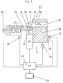
- Fig. 1 is a section of an ultrasonic welding device for welding electrical Conductor shown, as far as a compression space adjustable to the conductor to be welded (10) is affected.
- the ultrasonic welding device itself always correspond to a construction that corresponds to the RK 2000 or Minic Automatic from Schunk Ultrasound Technology GmbH, Wettenberg.
- the compression chamber (10) has a rectangular cross section in the exemplary embodiment and is open at the end to close the conductors to be welded through them to lead. Compression areas with other cross sections are of course also possible, especially with a trapezoidal cross-section.
- the compression space (10) is laterally by boundary surfaces (12), (14), (16) and (18) enclosed on the one hand by a section of a sonotrode (20) and on the other hand be limited by a multi-part counter electrode (22) such as anvil.
- the multi-part counter electrode (22) comprises a slide (24) which along the the boundary surface (12) provided for the sonotrode (12) is displaceable and forms the lateral boundary surface (14).
- the direction of movement of the slider (24) is indicated by the arrow (S2).
- the slide (24) is opposite second part (26) of the counter electrode (22) arranged parallel to the boundary surface (14), that is to say displaceable perpendicular to the sonotrode surface (12) (S1).
- the second part (26) slidably takes a section (28) to be called a nose on, which is movable according to the arrow (S3) parallel to the surface (12).
- the compression space (10) is used to compact the inserted conductor, that is to say Pre-compaction, set to a previously defined height-width ratio. This is in Fig. 1 by different rectangles drawn in the compression space Symbolizes greatness.
- the slide (24) is provided with a drive (36), in particular a pneumatic or hydraulic drive, connected by the slide (24) in the direction of the arrow S2 and vice versa is movable.
- the part (26) of the counter electrode (22) is with a Drive (38) connected, which is also preferably a pneumatic or hydraulic Drive can be formed.
- the part (26) can be displaced in the direction of the arrow S1 and vice versa by means of the drive (38).
- the slide (24) is also connected to a position sensor (40) which the position of the slide (24) can be measured with respect to a rest position. That too Part (26) is connected to a position sensor (42) with which the position of the part (26) can be determined in relation to a rest position.
- a control device (46), e.g. a programmable logic controller is available with the Position sensors (40), (42), the ultrasound set sonotrode (20) and not Connected controls for the drives (36), (38) connected. To the A monitor (48) is connected to the control device (46).
- the height (h) and / or the width (b) of the precompression chamber (10) is determined by means of at least one position sensor, in the exemplary embodiment of the position sensors (40), (42) generated measured values and evaluated by the control device (46).
- Different cross sections or different heights or widths of the compression area (10) various parameters are associated with the ultrasonic welding device for welding the conductors. It is a matter of Welding parameters such as welding energy, welding amplitude, welding time and welding pressure.
- a force sensor (50) can also be connected to the part (26), with which the force sensor in the compression space (10) inserted conductor by means of the part (26) exerted force is measured.
- the force sensor is also connected to the control unit (46).
- indirect measurement can also be carried out by pressure control.
- the in the compression space (10) inserted conductor compacted by moving the slide (24) and the part (22) be that the cross section of the precompression chamber (10) is reduced.
- Forces for the setting of the cross section are from the control unit (46) to the drives (36), (38) triggering outgoing signals, the respective cross-section being established of the precompression chamber by means of the measuring range generated by the position sensors (40), (42) is determined by the control unit (46).
- the cross section or the height or the width of the precompression chamber (10) at the end or after completion of the pre-compression is therefore a measure of the degree of Pre-compression, i.e. the geometry of the pre-compression space can be used as a pre-compression dimension or compacting dimension can be used or evaluated. Because e.g. only that Width (b) and / or the height (h) of the precompression chamber (10) can be changed the cross-section can be determined quickly and easily.
- the force exerted on the conductor can also be can be used as a precompression measure.
- the cross-section is basically only the height or the width of the pre-compression space changed again, the one at or after completion the existing cross-section of the weld is a measure of the quality of the weld the leader is.
- step (52) which is labeled "Start” in FIG. 2, the ultrasonic welding device set in motion. Then in a step (54) certain strand combination inserted in the compression chamber (10). Subsequently the manufacturing process for the welded conductors is started in a step (56). Then in a step (58) the compression chamber (10) is closed by the Slider (24) and the part (26) in directions indicated by the arrows (S2) and (S1) are designated, driven or moved. In Fig. 2, step (58) is with "Close tools" called.
- step (58) or thereafter an ultrasound pulse or sequence generated to compact the conductors more. This actually takes place Meaning an equalization of the compacting (step (60)).
- step (62) After compacting in a subsequent step (62) the compacting dimension from the Geometry of the compression space by knowing the width and / or height or another specific size is determined.
- a step follows (64), in which the determined compacting dimension first with an upper and a lower "outer" limit is compared.
- the upper and lower outer limits are set when setting up the ultrasonic welding device certainly.
- the limits set the external limits for the Press dimensions fixed.
- the compacting dimension with an upper and lower “inner” limit compared.
- the upper and lower “inner” limit will be from the nominal value of the press size plus a first tolerance value and minus a second tolerance value is determined.
- the tolerance values do not have to be the same be great.
- a step (66) follows in which an optical and / or acoustic error message is generated, which leads to a step (68) in which the tools are opened so that the manufacturing process is no longer is continued.
- the conductors can be removed from the ultrasonic welding device will.
- Step (70) is written into a statistic which is stored in a file in the control unit (46) is available.
- the error is acknowledged or when the external one is exceeded Limits of the process are checked and corrected if necessary.
- the compacting dimension is within the limits included Ranges, then follows a method step (74), in which, from compacting dimensions measured and stored in previous n-manufacturing processes or steps and the just determined value a new setpoint for the compacting dimension is determined.
- the compacting dimension is straight ongoing manufacturing process is therefore included.
- the setpoint is e.g. as an arithmetic Average value for testing the next welded manufacturing process Head determined.
- the number n is e.g. between 3 and 50. After setting up the ultrasonic welding device if no compacting dimension has been measured or determined the set-up dimension is specified as the setpoint.
- Step (74) is followed by step (76) in which the welding is carried out.
- the control unit (46) or device sets the assigned Welding parameters such as welding energy, welding amplitude, welding time and welding pressure a.
- the welding parameters are during the following, in Fig. 2 with energy control designated step (78) maintained.
- step (78) in Step (80) checks whether the time provided for the energy supply has been exceeded becomes.
- Step (78) also triggers a timer. Is the allowable Time is exceeded, the process moves to step (66).
- step (82) in which the weld size is determined.
- the sweat measure is as indicated above, the one measured at or after the end of the welding process Geometry with the height and / or width of the precompression chamber (10), which during the Welding is changed.
- the determination of the welding dimension is the same as the determination of the compacting dimension by means of the measured values generated by the position sensors (40), (42).
- a step follows (84) by comparing the determined weld size with limit values. Given are an upper and lower "outer” fixed limit. The two fixed outer ones Limit values are determined when setting up the ultrasonic welding device. Furthermore, the weld size with an upper and lower “inner” limit compared. The internal limit values are derived from the target values of the weld size plus a first tolerance value and minus a second tolerance value. If an upper limit value of the determined weld size is exceeded or on below the lower limit value, step (66) is then carried out as the next step. The tolerance values do not have to be the same size.
- Step (86) the manufacturing process with one step (86) continued, in which a new setpoint for the weld size from n values as arithmetic Mean is calculated.
- the n values refer to the last one found Value and the welding dimensions determined in the previous manufacturing steps.
- Step (88) the ultrasound device by opening the tools, i.e. by the Opening of the pre-compressor chamber (10) released for the removal of the weld product.
- the weld is carried out in one Number of correct weld counters taken into account. The at the Welding existing parameters are written into a statistics file.
- step (92) which is labeled "end" is indicated.
- a new manufacturing process begins after removal of the welding product with the ultrasonic welding device ready for operation with step (54).
- Fig. 3 shows an example of several in different manufacturing steps, each comprise at least steps (54) to (90), depending on certain compacting dimensions on the timing of the steps.
- the values of the compacting dimensions K are plotted in the ordinate direction, while the number n of compactings is shown in the abscissa direction.
- the compacting dimensions (94), (96), (98), (100), (102), (104), (106), (108), (110) are shown as actual values and can be averaged Curve (112) can be connected.
- An outer upper limit (114) and an outer lower limit (116) are as comparison values by means of the machine determined and constant. From the arithmetic mean of n compacting dimensions (n e.g. 3 ...
- a Setpoint (122) is set at the beginning of the process by setting up the machine set.
- the above procedure allows a continuous review of the manufacturing processes of welded conductors or strands.
- the manufacturing processes are through the Control device (46) controlled.
Description
Die Erfindung bezieht sich auf ein Verfahren zum Kompaktieren und anschließenden Verschweißen von elektrischen Leitern, insbesondere zur Herstellung von Durchgangs-oder Endknoten von Litzen mittels Ultraschall in einem an die Leiter anpassbaren Verdichtungsraum, wobei die zu verschweißenden Leiter zunächst kompaktiert und sodann verschweißt werden.The invention relates to a method for compacting and subsequent Welding of electrical conductors, in particular for the production of through or End nodes of strands using ultrasound in a compression space that can be adapted to the conductor, whereby the conductors to be welded are first compacted and then be welded.
Zum Kompaktieren und anschließenden Verschweißen von elektrischen Leitern, insbesondere zur Herstellung von Durchgangs- und Endknoten von Litzen, werden Ultraschallschweißvorrichtungen eingesetzt, die Sonotroden für die Erzeugung von Ultraschallschwingungen aufweisen. Ein Abschnitt der jeweiligen Sonotrode bildet eine erste seitliche Begrenzungsfläche eines z. B. in Höhe und Breite verstellbaren, stirnseitig offenen Verdichtungsraums. Die anderen Begrenzungsflächen des Verdichtungsraums können Abschnitte einer mehrteiligen Gegenelektrode sein. Beispiele für Ultraschallschweißvorrichtungen sind unter den Bezeichnungen RK 2000 oder Minic Automatic der Schunk Ultraschalltechnik GmbH, Wettenberg, Bundesrepublik Deutschland, angebotene Geräte.For compacting and subsequent welding of electrical conductors, in particular for the manufacture of through and end knots of strands, ultrasonic welding devices used the sonotrodes for the generation of Have ultrasonic vibrations. A section of the respective sonotrode forms one first lateral boundary surface of a z. B. adjustable in height and width, front open compression space. The other boundary surfaces of the compression room can be sections of a multi-part counter electrode. Examples of ultrasonic welding devices are under the names RK 2000 or Minic Automatic the Schunk Ultrasonic Technology GmbH, Wettenberg, Federal Republic of Germany, offered equipment.
Um den heutigen Anforderungen zu genügen, muß sichergestellt sein, daß Materialänderungen bzw. ein Wechsel von die Ultraschallschweißvorrichtung bedienenden Personen einen Einfluß auf die verschweißten Endprodukte nicht zeigen.In order to meet today's requirements, it must be ensured that material changes or a change from operating the ultrasonic welding device Do not show people any influence on the welded end products.
Der Erfindung liegt daher das Problem zugrunde, ein Verfahren der eingangs beschriebenen Art dahingehend weiterzuentwickeln, daß aus während der für die Erzeugung verschweißter elektrischer Leiter ablaufenden Arbeitsgänge gewonnenen Parametern, die für die Eigenschaften der hergestellten Produkte maßgebend sind, automatisch sichergestellt werden kann, daß die verschweißten Produkte innerhalb zulässiger enger Fertigungstoleranzen liegen.The invention is therefore based on the problem of a method as described in the introduction Kind to develop in such a way that from the welded for the generation electrical conductors operations obtained parameters that decisive for the properties of the manufactured products are automatically ensured can be that the welded products within narrower allowable Manufacturing tolerances lie.
Das Problem wird bei einem Verfahren der eingangs beschriebenen Art erfindungsgemäß dadurch gelöst, daß nach der Kompaktierung der Leiter ein die Größe der Kompaktierung angebender Wert gemessen oder aus Meßwerten bestimmt und wenigstens mit einem vorgegebenen oberen und einem unteren, auf einen Sollwert bezogenen Grenzwert verglichen wird, daß bei einem Wert, der außerhalb des durch die Grenzwerte eingeschlossenen Bereichs liegt, die Schweißung nicht ausgeführt und bei einem Wert, der innerhalb des durch die Grenzwerte eingeschlossenen Bereichs liegt, der Wert mit bei vorherigen Arbeitsgängen bestimmten Werten zu einem neuen Sollwert für die Überprüfung nachfolgender Kompaktierarbeitsgänge verrechnet wird und die Schweißung ausgeführt wird und/oder daß ein bei oder nach Beendigung der Schweißung vorhandener Wert wenigstens einer für den Schweißvorgang maßgeblichen Größe gemessen oder aus Meßwerten bestimmt und wenigstens mit einem oberen und unteren, auf einen Sollwert bezogenen Grenzwert verglichen wird und daß bei einem außerhalb des durch die Grenzwerte eingeschlossenen Bereichs liegenden Wert ein Fehler angezeigt und bei einem innerhalb dieses Bereichs liegenden Wert dieser mit bei vorherigen Arbeitsgängen bestimmten Werten zu einem neuen Sollwert für die Überprüfung nachfolgender Schweißarbeitsgänge verrechnet wird. Mit diesem Verfahren werden Sollwerte, mit denen die Arbeitsweise der Ultraschallschweißvorrichtung während des Ablaufs des Herstellungsverfahrens geprüft wird, mittels der während aufeinanderfolgender Herstellungsarbeitsgänge oder -prozesse gemessener Ist-Werte fortlaufend den jeweiligen Gegebenheiten angepaßt. Hierdurch ist erstmalig die Möglichkeit gegeben, daß die für das Kompaktieren bzw. Schweißen charakteristischen Parameter dynamisch an das vorausgegangene Verdichten bzw. Schweißen angepaßt werden. Somit erfolgt eine weitere Verbesserung der Fertigungstoleranzen aufgrund einer dynamischen Sollwertanpassung. Ferner kann hierdurch eine dynamische Anpassung an die tatsächliche Prozeßstreuung vorgenommen werden.The problem is solved according to the invention in a method of the type described in the introduction solved in that after the compaction of the ladder the size of the Compacting value measured or determined from measured values and at least with a predetermined upper and a lower, related to a setpoint Limit value is compared to a value that is outside of the limit values included area, the weld is not carried out and at a Value that is within the range of the limits, the value with values determined in previous operations to a new setpoint for the Checking subsequent compacting operations is charged and the welding is carried out and / or that at or after completion of the weld existing value of at least one parameter relevant to the welding process measured or determined from measured values and at least with an upper and lower, a limit value related to a target value is compared and that with an outside an error is displayed in the value within the range covered by the limit values and if the value is within this range, it is the same with previous values Operations specific values to a new setpoint for review subsequent welding operations is charged. With this procedure Setpoints with which the operation of the ultrasonic welding device during the Flow of the manufacturing process is checked by means of during successive Manufacturing operations or processes of measured actual values continuously adapted to specific circumstances. This gives the opportunity for the first time that the parameters characteristic of compacting or welding are dynamic to be adapted to the previous compression or welding. So it happens a further improvement in manufacturing tolerances due to a dynamic setpoint adjustment. This also allows a dynamic adaptation to the actual Process dispersion can be made.
Auf diese Weise werden gleichmäßige Schweißergebnisse erzielt. Weiterhin wird verhindert, daß bei Abweichungen von notwendigen Herstellungsbedingungen Produkte erzeugt bzw. nicht als fehlerhaft erkannt werden.In this way, uniform welding results are achieved. Will continue prevents products from deviating from the necessary manufacturing conditions generated or not recognized as faulty.
Bei einer bevorzugten Ausführungsform werden die Leiter während der Kompaktierung mit Ultraschall beaufschlagt. Die Stärke dieser Ultraschallbeaufschlagung ist geringer als die für die Verschweißung der Leiter notwendige Stärke. Die zusätzliche Ultraschallbehandlung während der Kompaktierung bewirkt, daß die Leiter stärker kompaktiert werden, was für die nachfolgende Messung und Schweißung besonders günstig ist.In a preferred embodiment, the conductors are during the compaction subjected to ultrasound. The strength of this ultrasound exposure is lower than the thickness necessary for welding the conductors. The additional ultrasound treatment during compaction causes the conductor to compact more become what is particularly favorable for the subsequent measurement and welding.
Mit anderen Worten wird durch einen sogenannten Ultraschallvorimpuls bzw. eine Vorimpulsfolge eine Vergleichmäßigung des Kompaktierens erreicht.In other words, a so-called ultrasonic pre-pulse or Pre-pulse sequence achieved an equalization of the compacting.
Die Ultraschallbehandlung der Leiter während des Kompaktierens hat eigenständigen erfinderischen Gehalt, da sie auch ohne die oben beschriebene Sollwertanpassung zu einer Verbesserung bei der nachfolgenden Verschweißung führt. The ultrasound treatment of the conductors during compacting has its own inventive content, since it also without the above-described setpoint adjustment leads to an improvement in the subsequent welding.
Als Größe, die den Schweißvorgang maßgeblich beeinflußt, kann der Querschnitt des Verdichtungsraums ausgewählt werden, der von den Leitern bei oder nach Beendigung des Schweißarbeitsgangs eingenommen bzw. ausgefüllt wird. Insbesondere ist jedoch die Höhe oder die Breite des Verdichtungsraums als maßgebender Parameter auszuwählen.As a size that significantly influences the welding process, the cross section of the Compression room can be selected by the conductors at or after termination of the welding process is taken or filled out. In particular, however select the height or the width of the compression space as the decisive parameter.
Bei einer weiteren bevorzugten Ausführungsform werden jeweils der bei oder nach Beendigung der Kompaktierung gemessene oder aus Meßwerten bestimmte Wert und/oder der bei oder nach Beendigung der Schweißung gemessene oder aus Meßwerten bestimmte Wert des Schweißmaßes je mit einem fest vorgegebenen oberen und unteren Grenzwert und mit einem weiteren oberen und unteren Grenzwert verglichen, der sich jeweils aus dem für den jeweiligen Arbeitsgang des Herstellungsprozesses berechneten Sollwert für die Kompaktierung bzw. Schweißung zuzüglich eines zulässigen positiven oder negativen Toleranzwertes zusammensetzt. Die fest vorgegebenen Grenzwerte, die im folgenden auch als äußere Grenzwerte bezeichnet werden, werden beim Einrichten der für die Durchführung des Verfahrens vorgesehenen Ultraschallschweißvorrichtung bestimmt und gespeichert. Die mit Hilfe der Sollwerte gebildeten Grenzwerte, die im folgenden auch als innere Grenzwerte bezeichnet werden, erlauben es, geringe Abweichungen zwischen aufeinanderfolgenden Herstellungsabläufen zu erfassen. Daraus lassen sich Rückschlüsse auf Tendenzen ziehen, die material- oder vorrichtungsbedingt sind und die Qualität in unerwünschter Weise beeinflussen. Es lassen sich z.B. Langzeiteinflüsse verfolgen, wodurch vorbeugende Maßnahmen zur Vermeidung eines Vorrichtungsausfalls bzw. zur Gewährleistung einer gleichbleibenden Produktqualität getroffen werden können.In a further preferred embodiment, the at or after Completion of the compacting measured value or determined from measured values and / or the values measured at or after the end of the weld or from measured values specific value of the weld size with a fixed upper and lower Limit and compared with another upper and lower limit, the in each case from that calculated for the respective work step of the manufacturing process Setpoint for the compacting or welding plus a permissible positive or negative tolerance value. The fixed limit values, the are also referred to below as external limit values when setting up the ultrasonic welding device provided for carrying out the method determined and saved. The limit values formed with the help of the setpoints The following are also referred to as internal limit values, which allow slight deviations between successive manufacturing processes. Out of it conclusions can be drawn about trends that are material or device-related are and affect the quality in an undesirable manner. For example, Long-term influences pursue what preventive measures to avoid Device failure or to ensure consistent product quality can be hit.
Insbesondere lassen sich jedoch durch das erfindungsgemäße Verfahren bereits kleine Fehler sicher erkennen. In particular, however, the method according to the invention enables even small ones Detect errors safely.
Vorzugsweise werden die Sollwerte als arithmetische Mittelwerte aus mehreren Werten vorangegangener Herstellungsschritte berechnet. Die Anzahl der zur Bestimmung der Mittelwerte heranzuziehenden Meßwerte kann zwischen einigen und zig Werten liegen. Bei dem unmittelbar auf das Einrichten der Ultraschallschweißvorrichtung folgenden Herstellungsschritt werden die beim Einrichten ermittelten Sollwerte verwendet.The setpoints are preferably used as arithmetic mean values from several values previous manufacturing steps calculated. The number of to determine the Measured values to be used as mean values can be between a few and tens of values. The one immediately following the setting up of the ultrasonic welding device Manufacturing step, the setpoints determined during setup are used.
Bei der Über- bzw. Unterschreitung der äußeren oder inneren Grenzwerte werden zweckmäßigerweise Fehlermeldungen erzeugt und die während des fehlerhaften Arbeitsablaufs gemessenen Werte für die nachfolgende Auswertung gespeichert.If the external or internal limit values are exceeded or undershot expediently generates error messages and that during the faulty workflow measured values for the subsequent evaluation.
Die erfindungsgemäße Lehre ist auch auf ein Verfahren zum Schweißen und gegebenenfalls vorherigen Kompaktieren von Material wie Kunststoffmaterial wie -pulver mittels Ultraschall in einem das Material aufnehmenden Verdichtungsraum anwendbar, das sich dadurch auszeichnet, daß ein bei oder nach Beendigung der Schweißung vorhandener Wert wenigstens einer für den Schweißvorgang maßgeblichen Größe gemessen oder aus Meßwerten bestimmt und wenigstens mit einem oberen und unteren, auf einen Sollwert bezogenen Grenzwert verglichen wird und daß bei einem außerhalb des durch die Grenzwerte eingeschlossenen Bereichs liegenden Wert ein Fehler angezeigt und bei einem innerhalb dieses Bereichs liegenden Wert dieser mit bei vorherigen Arbeitsgängen bestimmten Werten zu einem neuen Sollwert für die Überprüfung nachfolgender Schweißarbeitsgänge verrechnet wird und/oder daß nach der Kompaktierung des Materials ein die Größe der Kompaktierung angebender Wert gemessen oder aus Meßwerten bestimmt und wenigstens mit einem vorgegebenen oberen und einem unteren, auf einen Sollwert bezogenen Grenzwert verglichen wird, daß bei einem Wert, der außerhalb des durch die Grenzwerte eingeschlossenen Bereichs liegt, die Schweißung nicht ausgeführt und bei einem Wert, der innerhalb des durch die Grenzwerte eingeschlossenen Bereichs liegt, der Wert mit bei vorherigen Arbeitsgängen bestimmten Werten zu einem neuen Sollwert für die Überprüfung nachfolgender Kompaktierarbeitsgänge verrechnet wird und die Schweißung ausgeführt wird. The teaching according to the invention is also based on a method for welding and, if appropriate previously compacting material such as plastic material and powder by means of Ultrasound can be used in a compression space that accommodates the material characterized in that an existing at or after completion of the weld Value of at least one parameter relevant to the welding process measured or from Measured values determined and at least with an upper and lower, to a target value related limit value is compared and that at an outside of the by the Limit values included range an error is displayed and at a value within this range with this in previous operations certain values to a new setpoint for checking subsequent ones Welding operations are charged and / or that after the compaction of the Measured or measured a value indicating the size of the compaction Measured values determined and at least with a predetermined upper and a lower limit value related to a target value is compared, that at a value which is outside the range enclosed by the limit values, the weld not executed and at a value that is within the limits included range, the value determined with previous operations Values for a new setpoint for checking subsequent compacting operations is charged and the welding is carried out.
Ausgestaltungen ergeben sich aus den vorstehend und nachstehend im Ausführungsbeispiel erfolgten Erläuterungen, in denen als Material elektrische Leiter angegeben sind, die jedoch sinngemäß durch Kunststoffmaterial wie -pulver ersetzt werden können.Refinements result from the above and below in the exemplary embodiment made explanations in which electrical material is specified as the material are, but can be replaced by plastic material and powder.
Weitere Einzelheiten, Vorteile und Merkmale der Erfindung ergeben sich nicht nur aus den Ansprüchen, den diesen zu entnehmenden Merkmalen - für sich und/oder in Kombination -, sondern auch aus der nachfolgenden Beschreibung eines der Zeichnung zu entnehmenden bevorzugten Ausführungsbeispiels.Further details, advantages and features of the invention do not only result from the claims, the features to be extracted from them - for themselves and / or in Combination - but also from the following description of one of the drawings to be taken preferred embodiment.
Es zeigen:
- Fig. 1
- einen Ausschnitt einer Ultraschallschweißvorrichtung mit einem veränderbaren Verdichtungsraum,
- Fig. 2
- ein Fließbild eines mit der Vorrichtung gemäß Fig. 1 ausgeübten Verfahrens zum Verschweißen von insbesondere elektrischen Leitern und
- Fig. 3
- ein Zeitdiagramm eines typischen Verlaufs von Ist- und Sollwerten einer Ultraschallschweißvorrichtung gemäß Fig. 1 während der Herstellung von miteinander verschweißten Litzen in aufeinanderfolgenden Herstellungsschritten.
- Fig. 1
- a section of an ultrasonic welding device with a variable compression space,
- Fig. 2
- a flow chart of a method practiced with the device according to FIG. 1 for welding in particular electrical conductors and
- Fig. 3
- a time diagram of a typical course of actual and target values of an ultrasonic welding device according to FIG. 1 during the manufacture of strands welded together in successive manufacturing steps.
In Fig. 1 ist ein Ausschnitt einer Ultraschallschweißvorrichtung zum Verschweißen elektrischer Leiter dargestellt, soweit ein auf zu verschweißende Leiter einstellbarer Verdichtungsraum (10) betroffen ist. Dabei kann die Ultraschallschweißvorrichtung selbst grundsätzlich einer Konstruktion entsprechen, die dem Gerät RK 2000 oder Minic Automatic der Schunk Ultraschalltechnik GmbH, Wettenberg, entspricht. In Fig. 1 is a section of an ultrasonic welding device for welding electrical Conductor shown, as far as a compression space adjustable to the conductor to be welded (10) is affected. The ultrasonic welding device itself always correspond to a construction that corresponds to the RK 2000 or Minic Automatic from Schunk Ultrasound Technology GmbH, Wettenberg.
Der Verdichtungsraum (10) weist im Ausführungsbeispiel einen rechteckigen Querschnitt auf und ist stirnseitig offen, um durch diesen die zu verschweißenden Leiter zu führen. Verdichtungsräume mit anderen Querschnitten sind selbstverständlich auch möglich, wie insbesondere mit einem trapezförmigen Querschnitt.The compression chamber (10) has a rectangular cross section in the exemplary embodiment and is open at the end to close the conductors to be welded through them to lead. Compression areas with other cross sections are of course also possible, especially with a trapezoidal cross-section.
Der Verdichtungsraum (10) wird seitlich von Begrenzungsflächen (12), (14), (16) und (18) umschlossen, die einerseits von einem Abschnitt einer Sonotrode (20) und andererseits von einer mehrteiligen Gegenelektrode (22) wie Amboß begrenzt werden.The compression space (10) is laterally by boundary surfaces (12), (14), (16) and (18) enclosed on the one hand by a section of a sonotrode (20) and on the other hand be limited by a multi-part counter electrode (22) such as anvil.
Die mehrteilige Gegenelektrode (22) umfaßt einen Schieber (24), der entlang der von der Sonotrode (12) zur Verfügung gestellten Begrenzungsfläche (12) verschiebbar ist und die seitliche Begrenzungsfläche (14) bildet. Die Bewegungsrichtung des Schiebers (24) ist durch den Pfeil (S2) angedeutet. Dem Schieber (24) gegenüberliegend ist ein zweites Teil (26) der Gegenelektrode (22) angeordnet, welches parallel zur Begrenzungsfläche (14), also senkrecht zur Sonotrodenfläche (12) verschiebbar ist (S1). Das zweite Teil (26) nimmt einen als Nase zu bezeichnenden Abschnitt (28) verschiebbar auf, welche entsprechend dem Pfeil (S3) parallel zur Fläche (12) bewegbar ist.The multi-part counter electrode (22) comprises a slide (24) which along the the boundary surface (12) provided for the sonotrode (12) is displaceable and forms the lateral boundary surface (14). The direction of movement of the slider (24) is indicated by the arrow (S2). The slide (24) is opposite second part (26) of the counter electrode (22) arranged parallel to the boundary surface (14), that is to say displaceable perpendicular to the sonotrode surface (12) (S1). The second part (26) slidably takes a section (28) to be called a nose on, which is movable according to the arrow (S3) parallel to the surface (12).
Der von den Begrenzungsflächen (12), (14), (16) und (18) umschlossene Raum wird in Abhängigkeit von den jeweils zu verschweißenden Leitern verändert.The space enclosed by the boundary surfaces (12), (14), (16) and (18) is shown in Dependency on the conductors to be welded changed.
Der Verdichtungsraum (10) wird zum Kompaktieren der eingelegten Leiter, also zum Vorverdichten, auf ein zuvor festgelegtes Höhen-Breiten-Verhältnis eingestellt. Dies ist in Fig. 1 durch in den Verdichtungsraum eingezeichnete Rechtecke unterschiedlicher Größe symbolisiert.The compression space (10) is used to compact the inserted conductor, that is to say Pre-compaction, set to a previously defined height-width ratio. This is in Fig. 1 by different rectangles drawn in the compression space Symbolizes greatness.
Der Schieber (24) ist mit einem Antrieb (36), insbesondere einem pneumatischen oder hydraulischen Antrieb, verbunden, durch den der Schieber (24) in Richtung des Pfeils S2 und umgekehrt bewegbar ist. Das Teil (26) der Gegenelektrode (22) ist mit einem Antrieb (38) verbunden, der ebenfalls vorzugsweise als pneumatischer oder hydraulischer Antrieb ausgebildet sein kann.The slide (24) is provided with a drive (36), in particular a pneumatic or hydraulic drive, connected by the slide (24) in the direction of the arrow S2 and vice versa is movable. The part (26) of the counter electrode (22) is with a Drive (38) connected, which is also preferably a pneumatic or hydraulic Drive can be formed.
Mittels des Antriebs (38) ist das Teil (26) in Richtung des Pfeils S1 und umgekehrt verschiebbar. Der Schieber (24) ist weiterhin mit einem Lagegeber (40) verbunden, mit dem die Stellung des Schiebers (24) in bezug auf eine Ruhelage meßbar ist. Auch das Teil (26) ist mit einem Lagegeber (42) verbunden, mit dem die Stellung des Teils (26) in bezug auf eine Ruhelage festgestellt werden kann.The part (26) can be displaced in the direction of the arrow S1 and vice versa by means of the drive (38). The slide (24) is also connected to a position sensor (40) which the position of the slide (24) can be measured with respect to a rest position. That too Part (26) is connected to a position sensor (42) with which the position of the part (26) can be determined in relation to a rest position.
Eine Steuereinrichtung (46), z.B. eine speicherprogrammierbare Steuerung ist mit den Lagegebern (40), (42), der Ultraschall abgebundenen Sonotrode (20) sowie mit nicht näher dargestellten Steuerelementen für die Antriebe (36), (38) verbunden. An die Steuereinrichtung (46) ist ein Monitor (48) angeschlossen.A control device (46), e.g. a programmable logic controller is available with the Position sensors (40), (42), the ultrasound set sonotrode (20) and not Connected controls for the drives (36), (38) connected. To the A monitor (48) is connected to the control device (46).
Die Höhe (h) und/oder die Breite (b) des Vorverdichtungsraums (10) wird mittels zumindest eines Lagegebers, im Ausführungsbeispiel von den Lagegebern (40), (42) erzeugten und von der Steuereinrichtung (46) ausgewerteten Meßwerten bestimmt. Verschiedenen Querschnitten bzw. unterschiedlichen Höhen oder Breiten des Verdichtungsraums (10) sind verschiedene Parameter zugeordnet, die mit der Ultraschallschweißvorrichtung zum Schweißen der Leiter eingestellt werden. Es handelt sich um Schweißparameter wie Schweißenergie, Schweißamplitude, Schweißzeit und Schweißdruck.The height (h) and / or the width (b) of the precompression chamber (10) is determined by means of at least one position sensor, in the exemplary embodiment of the position sensors (40), (42) generated measured values and evaluated by the control device (46). Different cross sections or different heights or widths of the compression area (10) various parameters are associated with the ultrasonic welding device for welding the conductors. It is a matter of Welding parameters such as welding energy, welding amplitude, welding time and welding pressure.
Während des Schweißens wird insbesondere die Höhe (h) des Verdichtungsraums (10) verändert, wobei die Breite (b) gleich bleibt, da z.B. nach dem Abschluß einer auf die Leiter ausgeübten Vorverdichtung der Schieber (24) arretiert wird.During welding, in particular the height (h) of the compression space (10) changed, whereby the width (b) remains the same, e.g. after completing one on the Conducted pre-compression of the slide (24) is locked.
Mit dem Teil (26) kann auch ein Kraftsensor (50) verbunden sein, mit dem die auf die in den Verdichtungsraum (10) eingelegten Leiter mittels des Teils (26) ausgeübte Kraft gemessen wird. Der Kraftsensor ist ebenfalls an die Steuereinheit (46) angeschlossen. Selbstverständlich kann auch eine indirekte Messung durch Druckregelung erfolgen.A force sensor (50) can also be connected to the part (26), with which the force sensor in the compression space (10) inserted conductor by means of the part (26) exerted force is measured. The force sensor is also connected to the control unit (46). Of course, indirect measurement can also be carried out by pressure control.
Mit der oben beschriebenen Vorrichtung werden die in den Verdichtungsraum (10) eingelegten Leiter kompaktiert, indem der Schieber (24) und das Teil (22) so bewegt werden, daß der Querschnitt des Vorverdichtungsraums (10) reduziert wird. Kräfte für die Einstellung des Querschnitts werden von der Steuereinheit (46) über an die Antriebe (36), (38) ausgehende Signale ausgelöst, wobei der jeweils sich einstellende Querschnitt des Vorverdichtungsraums mittels der von den Lagegebern (40), (42) erzeugten Meßweite von der Steuereinheit (46) bestimmt wird.With the device described above, the in the compression space (10) inserted conductor compacted by moving the slide (24) and the part (22) be that the cross section of the precompression chamber (10) is reduced. Forces for the setting of the cross section are from the control unit (46) to the drives (36), (38) triggering outgoing signals, the respective cross-section being established of the precompression chamber by means of the measuring range generated by the position sensors (40), (42) is determined by the control unit (46).
Der Querschnitt bzw. die Höhe oder die Breite des Vorverdichtungsraums (10) am Ende oder nach Beendigung der Vorverdichtung ist demnach ein Maß für den Grad der Vorverdichtung, d.h. die Geometrie des Vorverdichtungsraums kann als Vorverdichtungsmaß oder Kompaktiermaß verwendet bzw. ausgewertet werden. Da z.B. nur die Breite (b) und/oder die Höhe (h) des Vorverdichtungsraums (10) veränderbar sind, läßt sich der Querschnitt schnell und einfach bestimmen.The cross section or the height or the width of the precompression chamber (10) at the end or after completion of the pre-compression is therefore a measure of the degree of Pre-compression, i.e. the geometry of the pre-compression space can be used as a pre-compression dimension or compacting dimension can be used or evaluated. Because e.g. only that Width (b) and / or the height (h) of the precompression chamber (10) can be changed the cross-section can be determined quickly and easily.
Wenn ein Kraftsensor (50) vorhanden ist, kann auch die auf die Leiter ausgeübte Kraft als Vorverdichtungsmaß verwendet werden.If a force sensor (50) is present, the force exerted on the conductor can also be can be used as a precompression measure.
Während des Schweißvorgangs wird der Querschnitt -grundsätzlich nur die Höhe oder die Breite- des Vorverdichtungsraums erneut verändert, wobei der bei oder nach Beendigung des Schweißens vorhandene Querschnitt ein Maß für die Qualität der Schweißung der Leiter ist.During the welding process, the cross-section is basically only the height or the width of the pre-compression space changed again, the one at or after completion the existing cross-section of the weld is a measure of the quality of the weld the leader is.
Da das Kompaktiermaß und das Schweißmaß mittels Stellgliedern wie des Schiebers bzw. des Teils (26) einstellbar sind, werden in die Steuereinheit (46) entsprechende Sollwerte eingegeben. Weiterhin werden in die Steuereinheit (46) feste obere und untere Grenzwerte für die Kompaktiermaße und Schweißmaße eingegeben. Diese Grenzwerte werden als äußere Grenzwerte bezeichnet. Weitere Grenzwerte, die im folgenden als innere Grenzwerte bezeichnet werden und die jeweils eine obere und eine untere Grenze für das Kompaktiermaß und/oder das Schweißmaß bei der Herstellung von verschweißten Leitern festlegen, werden mit der Steuereinheit (46) bestimmt.Since the compacting dimension and the welding dimension by means of actuators such as the slide or of the part (26) are adjustable, are corresponding in the control unit (46) Setpoints entered. Furthermore, fixed upper and lower are in the control unit (46) Limit values for the compacting dimensions and welding dimensions entered. These limits are called external limits. Further limit values, which are referred to below as internal limits are referred to and each have an upper and a lower limit for the compacting dimension and / or the welding dimension in the production of welded Determine ladders are determined with the control unit (46).
Mit der oben beschriebenen Vorrichtung wird das folgende in Verbindung mit dem Fließschema der Fig. 2 beschriebene Verfahren ausgeübt.With the device described above, the following in connection with the Flow scheme of Fig. 2 method is exercised.
In einem ersten Schritt (52), der in Fig. 2 mit "Start" bezeichnet ist, wird die Ultraschallschweißvorrichtung in Gang gesetzt. Danach wird in einem Schritt (54) eine bestimmte Litzenkombination in den Verdichtungsraum (10) eingelegt. Anschließend wird in einem Schritt (56) der Herstellungsprozeß für die verschweißten Leiter gestartet. Danach wird in einem Schritt (58) der Verdichtungsraum (10) geschlossen, indem der Schieber (24) und das Teil (26) in Richtungen, die durch die Pfeile (S2) und (S1) bezeichnet sind, angetrieben bzw. bewegt werden. In Fig. 2 ist der Schritt (58) mit "Werkzeuge schließen" bezeichnet.In a first step (52), which is labeled "Start" in FIG. 2, the ultrasonic welding device set in motion. Then in a step (54) certain strand combination inserted in the compression chamber (10). Subsequently the manufacturing process for the welded conductors is started in a step (56). Then in a step (58) the compression chamber (10) is closed by the Slider (24) and the part (26) in directions indicated by the arrows (S2) and (S1) are designated, driven or moved. In Fig. 2, step (58) is with "Close tools" called.
Während des Schritts (58) oder danach wird ein Ultraschallimpuls oder eine Folge davon erzeugt, um die Leiter stärker zu kompaktieren. Hierdurch erfolgt im eigentlichen Sinne eine Vergleichmäßigung des Kompaktierens (Schritt (60)). Nach dem Kompaktieren wird in einem anschließenden Schritt (62) das Kompaktiermaß aus der Geometrie des Verdichtungsraums, der durch die Kenntnis der Breite und/oder Höhe oder einer anderen spezifischen Größe bestimmt wird, ermittelt. Es folgt ein Schritt (64), in dem das ermittelte Kompaktiermaß zuerst mit einem oberen und einem unteren "äußeren" Grenzwert verglichen wird.During step (58) or thereafter, an ultrasound pulse or sequence generated to compact the conductors more. This actually takes place Meaning an equalization of the compacting (step (60)). After compacting in a subsequent step (62) the compacting dimension from the Geometry of the compression space by knowing the width and / or height or another specific size is determined. A step follows (64), in which the determined compacting dimension first with an upper and a lower "outer" limit is compared.
Der obere und der untere äußere Grenzwert werden beim Einrichten der Ultraschallschweißvorrichtung bestimmt. Die Grenzwerte legen die äußeren Grenzen für die Pressmaße fest. Danach wird das Kompaktiermaß mit einem oberen und unteren "inneren" Grenzwert verglichen. Der obere und der untere "innere" Grenzwert werden aus dem Sollwert des Pressmaßes zuzüglich eines ersten Toleranzwerts und abzüglich eines zweiten Toleranzwerts bestimmt. Die Toleranzwerte müssen dabei nicht gleich groß sein.The upper and lower outer limits are set when setting up the ultrasonic welding device certainly. The limits set the external limits for the Press dimensions fixed. Then the compacting dimension with an upper and lower "inner" limit compared. The upper and lower "inner" limit will be from the nominal value of the press size plus a first tolerance value and minus a second tolerance value is determined. The tolerance values do not have to be the same be great.
Wird ein oberer äußerer oder innerer Grenzwert überschritten oder ein unterer äußerer oder innerer Grenzwert unterschritten, dann folgt ein Schritt (66), in dem eine optische und/oder akustische Fehlermeldung erzeugt wird, was zu einem Schritt (68) führt, in dem die Werkzeuge geöffnet werden, so daß das Herstellungsverfahren nicht mehr fortgesetzt wird. Die Leiter können aus der Ultraschallschweißvorrichtung herausgenommen werden. Mit dem Öffnen der Werkzeuge oder danach wird der Fehler in einem Schritt (70) in eine Statistik eingeschrieben, die in einer Datei in der Steuereinheit (46) vorhanden ist. Bevor die Ultraschallschweißvorrichtung wieder starten kann, muß in einem Schritt (72) der Fehler quittiert werden bzw. bei Überschreiten der äußeren Grenzen der Prozeß überprüft und gegebenenfalls korrigiert werden.If an upper outer or inner limit is exceeded or a lower outer limit or the internal limit is undershot, then a step (66) follows in which an optical and / or acoustic error message is generated, which leads to a step (68) in which the tools are opened so that the manufacturing process is no longer is continued. The conductors can be removed from the ultrasonic welding device will. With the opening of the tools or afterwards the error is in one Step (70) is written into a statistic which is stored in a file in the control unit (46) is available. Before the ultrasonic welding device can start again, in in a step (72) the error is acknowledged or when the external one is exceeded Limits of the process are checked and corrected if necessary.
Wenn das Kompaktiermaß innerhalb der durch die Grenzwerte eingeschlossenen Bereiche liegt, dann folgt ein Verfahrensschritt (74), in dem aus Kompaktiermaßen, die in vorausgegangenen n-Herstellungsvorgängen bzw. -schritten gemessen und abgespeichert werden und dem gerade bestimmten Wert ein neuer Sollwert für das Kompaktiermaß bestimmt wird. In diese Kompaktiermaße ist das Kompaktiermaß des gerade ablaufenden Herstellungsvorgangs daher einbezogen. Der Sollwert wird z.B. als arithmetischer Mittelwert für die Prüfung des nächsten Herstellungsvorgangs verschweißter Leiter bestimmt. Die Zahl n beläuft sich z.B. zwischen 3 und 50. Nach dem Einrichten der Ultraschallschweißvorrichtung, wenn noch kein Kompaktiermaß gemessen oder bestimmt wurde, wird das Einrichtmaß als Sollwert vorgegeben. If the compacting dimension is within the limits included Ranges, then follows a method step (74), in which, from compacting dimensions measured and stored in previous n-manufacturing processes or steps and the just determined value a new setpoint for the compacting dimension is determined. In these compacting dimensions, the compacting dimension is straight ongoing manufacturing process is therefore included. The setpoint is e.g. as an arithmetic Average value for testing the next welded manufacturing process Head determined. The number n is e.g. between 3 and 50. After setting up the ultrasonic welding device if no compacting dimension has been measured or determined the set-up dimension is specified as the setpoint.
Auf den Schritt (74) folgt ein Schritt (76), in dem die Schweißung ausgeführt wird. Während dieses Schritts stellt die Steuereinheit (46) bzw. -einrichtung die zugeordneten Schweißparameter wie Schweißenergie, Schweißamplitude, Schweißzeit und Schweißdruck ein. Die Schweißparameter werden während des folgenden, in Fig. 2 mit Energieregelung bezeichneten Schritts (78) aufrechterhalten. Nach dem Schritt (78) wird im Schritt (80) geprüft, ob die für die Energiezuführung vorgesehene Zeit überschritten wird. Mit dem Schritt (78) wird nämlich auch ein Zeitglied angestoßen. Ist die zulässige Zeit überschritten, wird auf den Schritt (66) übergegangen.Step (74) is followed by step (76) in which the welding is carried out. During this step, the control unit (46) or device sets the assigned Welding parameters such as welding energy, welding amplitude, welding time and welding pressure a. The welding parameters are during the following, in Fig. 2 with energy control designated step (78) maintained. After step (78) in Step (80) checks whether the time provided for the energy supply has been exceeded becomes. Step (78) also triggers a timer. Is the allowable Time is exceeded, the process moves to step (66).
Ist die Zeitgrenze für die Energiezuführung eingehalten worden, dann wird auf einen Schritt (82) übergegangen, in dem das Schweißmaß ermittelt wird. Das Schweißmaß ist, wie oben angegeben, die bei oder nach dem Ende des Schweißvorgangs gemessene Geometrie mit Höhe und/oder Breite des Vorverdichtungsraums (10), der während des Schweißens verändert wird.If the time limit for the energy supply has been met, then one Moved to step (82) in which the weld size is determined. The sweat measure is as indicated above, the one measured at or after the end of the welding process Geometry with the height and / or width of the precompression chamber (10), which during the Welding is changed.
Die Bestimmung des Schweißmaßes geschieht wie die Bestimmung des Kompaktiermaßes mittels der von den Lagegebern (40), (42) erzeugten Meßwerte. Es folgt ein Schritt (84), in dem das ermittelte Schweißmaß mit Grenzwerten verglichen wird. Vorgegeben sind ein oberer und unterer "äußerer" fester Grenzwert. Die beiden festen äußeren Grenzwerte werden beim Einrichten der Ultraschallschweißvorrichtung bestimmt. Weiterhin wird das Schweißmaß mit einem oberen und unteren "inneren" Grenzwert verglichen. Die inneren Grenzwerte werden aus den Sollwerten des Schweißmaßes zuzüglich eines ersten Toleranzwertes und abzüglich eines zweiten Toleranzwertes bestimmt. Wird ein oberer Grenzwert vom ermittelten Schweißmaß überschritten oder ein unterer Grenzwert unterschritten, dann wird als nächster Schritt der Schritt (66) ausgeführt. Die Toleranzwerte müssen nicht gleich groß sein.The determination of the welding dimension is the same as the determination of the compacting dimension by means of the measured values generated by the position sensors (40), (42). A step follows (84) by comparing the determined weld size with limit values. Given are an upper and lower "outer" fixed limit. The two fixed outer ones Limit values are determined when setting up the ultrasonic welding device. Furthermore, the weld size with an upper and lower "inner" limit compared. The internal limit values are derived from the target values of the weld size plus a first tolerance value and minus a second tolerance value. If an upper limit value of the determined weld size is exceeded or on below the lower limit value, step (66) is then carried out as the next step. The tolerance values do not have to be the same size.
Liegt das Schweißmaß innerhalb der durch die äußeren und inneren Grenzwerte eingeschlossenen Bereiche, dann wird das Herstellungsverfahren mit einem Schritt (86) fortgesetzt, in dem ein neuer Sollwert für das Schweißmaß aus n Werten als arithmetischer Mittelwert berechnet wird. Die n Werte beziehen sich auf den zuletzt festgestellten Wert und die in den vorausgegangenen Herstellungsschritten festgestellten Schweißmaße. Nach der Berechnung und Abspeicherung des neuen Sollwerts wird im folgenden Schritt (88) die Ultraschallvorrichtung durch Öffnen der Werkzeuge, d.h. durch das Öffnen des Vorverdichterraums (10) für die Entnahme des Schweißprodukts freigegeben. In einen, weiteren Schritt (90) wird die ausgeführte Schweißung in einem die Anzahl einwandfreier Schweißungen angebenden Zähler berücksichtigt. Die bei der Schweißung vorhandenen Parameter werden in eine Statistikdatei eingeschrieben.If the weld size is within the limits set by the external and internal limits Areas, then the manufacturing process with one step (86) continued, in which a new setpoint for the weld size from n values as arithmetic Mean is calculated. The n values refer to the last one found Value and the welding dimensions determined in the previous manufacturing steps. After the calculation and storage of the new setpoint is as follows Step (88) the ultrasound device by opening the tools, i.e. by the Opening of the pre-compressor chamber (10) released for the removal of the weld product. In a further step (90), the weld is carried out in one Number of correct weld counters taken into account. The at the Welding existing parameters are written into a statistics file.
Das Herstellungsverfahren ist damit abgeschlossen, was in Fig. 2 mit dem Schritt (92), der mit "Ende" bezeichnet ist, angedeutet ist. Ein neues Herstellungsverfahren beginnt nach der Entnahme des Schweißprodukts bei betriebsbereiter Ultraschallschweißvorrichtung mit dem Schritt (54).The manufacturing process is now complete, which is shown in FIG. 2 with step (92), which is labeled "end", is indicated. A new manufacturing process begins after removal of the welding product with the ultrasonic welding device ready for operation with step (54).
Die Fig. 3 zeigt beispielhaft mehrere in verschiedenen Herstellungsschritten, die jeweils mindestens die Schritte (54) bis (90) umfassen, bestimmte Kompaktiermaße in Abhängigkeit von der zeitlichen Durchführung der Schritte. Die Werte der Kompaktiermaße K sind in Ordinatenrichtung aufgetragen, während die Anzahl n der Kompaktierungen in Abszissenrichtung dargestellt ist. Die Kompaktiermaße (94), (96), (98), (100), (102), (104), (106), (108), (110) sind als Istwert dargestellt und können durch eine gemittelte Kurve (112) miteinander verbunden werden. Ein äußerer oberer Grenzwert (114) und ein äußerer unterer Grenzwert (116) sind als Vergleichswerte durch Einrichtung der Maschine bestimmt und konstant. Aus den arithmetischen Mittelwerten von n Kompaktiermaßen (n z.B. 3 .... 50), die in aufeinanderfolgenden Herstellungsschritten bestimmt werden, werden mittels eines Toleranzmaßes, das den Mittelwerten hinzugefügt oder von diesen subtrahiert wird, eine innere, obere Grenze (118) und eine untere innere Grenze (120) bestimmt, deren jeweilige dem gleichen Zeitpunkt wie die Kompaktiermaße zugeordneten Werte bestimmt und mit diesen verglichen werden. Ein Sollwert (122) wird zu Beginn des Verfahrens durch das Einrichten der Maschine eingestellt. Mit der Verwendung der inneren Grenzwerte können Fehler trotz Langzeitflüsse auf das Herstellungsverfahren besser erkannt werden.Fig. 3 shows an example of several in different manufacturing steps, each comprise at least steps (54) to (90), depending on certain compacting dimensions on the timing of the steps. The values of the compacting dimensions K are plotted in the ordinate direction, while the number n of compactings is shown in the abscissa direction. The compacting dimensions (94), (96), (98), (100), (102), (104), (106), (108), (110) are shown as actual values and can be averaged Curve (112) can be connected. An outer upper limit (114) and an outer lower limit (116) are as comparison values by means of the machine determined and constant. From the arithmetic mean of n compacting dimensions (n e.g. 3 ... 50), in successive manufacturing steps are determined using a tolerance measure that is added to the mean values or subtracted from them, an inner upper limit (118) and one lower inner limit (120) determined, each at the same time as the Values assigned to compacting dimensions are determined and compared with these. A Setpoint (122) is set at the beginning of the process by setting up the machine set. With the use of the internal limit values, errors can occur despite long-term flows be better recognized on the manufacturing process.
Das obige Verfahren erlaubt eine fortlaufende Überprüfung der Herstellungsprozesse von verschweißten Leitern bzw. Litzen. Die Herstellungsprozesse werden durch die Steuereinrichtung (46) gesteuert.The above procedure allows a continuous review of the manufacturing processes of welded conductors or strands. The manufacturing processes are through the Control device (46) controlled.
Claims (11)
- A process for the compaction and subsequent welding of electric conductors, in particular for the production of through- or end nodes of stranded wires, using ultrasound in a compaction chamber (10) which can be adapted to the conductors, wherein the conductors to be welded are firstly compacted and then welded, characterised in that after the compaction of the conductors a value representing the degree of compaction is measured or is determined from measured values and is compared at least with one upper and one lower limit value relating to a setpoint value, that in the case of a value falling outside of the range defined by the limit values the welding is not performed, and in the case of a value falling within the range defined by the limit values the value is computed with values determined during previous operations to form a new setpoint value for the checking of subsequent compaction processes and the welding is performed, and/or that a value, occurring upon or after the termination of the welding, of at least one variable representing the welding process is measured or is determined from measured values and is compared at least with one upper and one lower limit value relating to a setpoint value, and that in the case of a value falling outside of the range defined by the limit values an error is displayed, and in the case of a value falling within this range said value is computed with values determined during previous operations to form a new setpoint value for the checking of subsequent welding operations.
- A process in particular according to Claim 1,
characterised in that during the compaction the conductors are subjected to ultrasound, the intensity of which is lower than the intensity required for welding. - A process according to Claim 1 or 2,
characterised in that the value governing the degree of compaction is the cross-section of the compaction chamber after the termination of the compaction or a value proportional to the cross-section. - A process according to Claim 1 or 2,
characterised in that the variable governing the welding process is the cross-section of the compaction chamber upon the termination of the welding or a value proportional to the cross-section. - A process according to one or more of the previous claims,
characterised in that the value measured upon or after the termination of the compaction or determined from measured values and/or the value measured upon or after the termination of the welding or determined from measured values is/are compared with a fixed upper and lower limit value and with a further upper and lower limit value, which limit value is in each case composed of the setpoint value, relating to the respective operation, for the compaction and welding respectively including a permissible positive or negative tolerance value. - A process according to one or more of the preceding claims,
characterised in that the setpoint values are preferably calculated as arithmetical mean values from a plurality of values of preceding production steps. - A process according to Claim 6,
characterised in that the number n of the values from preceding production steps used to determine the setpoint values is preferably between 3 and 50. - A process according to one or more of the preceding claims,
characterised in that the duration of the welding parameters during the welding is compared with a preset duration and that in the event of the overshooting of the preset duration an error message is generated. - A process according to one or more of the preceding claims,
characterised in that an error message is stored in a statistics data file and taken into consideration. - A process according to one or more of the preceding claims,
characterised in that in the case of compaction and welding values which fall within the upper and lower limit values, the welding process is stored in a statistics data file and taken into consideration and that the welding parameters are stored. - A process for the welding and optional previous compaction of material such as plastics material and powder using ultrasound in a compaction chamber accommodating the material wherein a value, occurring upon or after the termination of the welding, of at least one variable governing the welding process is measured or is determined from measured values and is compared at least with one upper and lower limit value relating to a setpoint value and in the case of a value falling outside of the range defined by the limit values an error is displayed and in the case of a value falling within this range said value is computed with values determined during previous operations to form a new setpoint value for the checking of subsequent welding operations and/or wherein, following the compaction of the material, a value indicating the degree of the compaction is measured or determined from measured values and is compared at least with one predetermined upper and lower limit value relating to a setpoint value and that in the case of a value falling outside of the range defined by the limit values the welding is not performed and in the case of a value falling within the range defined by the limit values the value is computed with values determined during previous operations to form a new setpoint value for the checking of subsequent compaction operations and the welding is performed.
Applications Claiming Priority (4)
| Application Number | Priority Date | Filing Date | Title |
|---|---|---|---|
| DE4429684A DE4429684A1 (en) | 1994-08-22 | 1994-08-22 | Method for compacting and welding of electric conductors, e.g. braid joints |
| DE4429729 | 1994-08-22 | ||
| DE4429729 | 1994-08-22 | ||
| DE4429684 | 1994-08-22 |
Publications (2)
| Publication Number | Publication Date |
|---|---|
| EP0701876A1 EP0701876A1 (en) | 1996-03-20 |
| EP0701876B1 true EP0701876B1 (en) | 1998-04-15 |
Family
ID=25939418
Family Applications (1)
| Application Number | Title | Priority Date | Filing Date |
|---|---|---|---|
| EP95112986A Expired - Lifetime EP0701876B1 (en) | 1994-08-22 | 1995-08-18 | Method for compacting and welding electrical wires |
Country Status (3)
| Country | Link |
|---|---|
| EP (1) | EP0701876B1 (en) |
| DE (1) | DE59501890D1 (en) |
| ES (1) | ES2116020T3 (en) |
Cited By (1)
| Publication number | Priority date | Publication date | Assignee | Title |
|---|---|---|---|---|
| DE10359368A1 (en) * | 2003-12-18 | 2005-07-14 | Schunk Ultraschalltechnik Gmbh | Ultrasonic welding of electrical conductors, e.g. stranded wires, applies pressure during welding and further ultrasonic action when relieved and measuring gap between sonotrode and counter electrode |
Families Citing this family (3)
| Publication number | Priority date | Publication date | Assignee | Title |
|---|---|---|---|---|
| KR20060102558A (en) | 2003-10-29 | 2006-09-27 | 쉔크 울트라샬테크니크 게엠베하 | Method for welding conductors |
| DE102013106349A1 (en) | 2013-05-13 | 2014-11-13 | Schunk Sonosystems Gmbh | Method for determining the degree of compaction of a node |
| JP7434546B2 (en) * | 2019-11-05 | 2024-02-20 | シュンク ソノジステム ゲゼルシャフト ミット ベシュレンクテル ハフツング | Ultrasonic welding equipment equipped with position detection of mating parts |
Family Cites Families (4)
| Publication number | Priority date | Publication date | Assignee | Title |
|---|---|---|---|---|
| EP0421018B1 (en) * | 1989-10-06 | 1994-03-16 | Siemens Aktiengesellschaft | Method and device for welding of metallic work-pieces with ultrasonic waves |
| WO1991009704A1 (en) * | 1989-12-28 | 1991-07-11 | Electric Power Research Institute | Method for joining transformer coil conductors |
| US5110381A (en) * | 1990-06-21 | 1992-05-05 | Heckard David P | Ultrasonic welding with controlled seal compression |
| RU1773643C (en) * | 1991-01-18 | 1992-11-07 | Конструкторское бюро точного электронного машиностроения | Installation for connecting wire outlets |
-
1995
- 1995-08-18 DE DE59501890T patent/DE59501890D1/en not_active Expired - Lifetime
- 1995-08-18 ES ES95112986T patent/ES2116020T3/en not_active Expired - Lifetime
- 1995-08-18 EP EP95112986A patent/EP0701876B1/en not_active Expired - Lifetime
Cited By (1)
| Publication number | Priority date | Publication date | Assignee | Title |
|---|---|---|---|---|
| DE10359368A1 (en) * | 2003-12-18 | 2005-07-14 | Schunk Ultraschalltechnik Gmbh | Ultrasonic welding of electrical conductors, e.g. stranded wires, applies pressure during welding and further ultrasonic action when relieved and measuring gap between sonotrode and counter electrode |
Also Published As
| Publication number | Publication date |
|---|---|
| ES2116020T3 (en) | 1998-07-01 |
| DE59501890D1 (en) | 1998-05-20 |
| EP0701876A1 (en) | 1996-03-20 |
Similar Documents
| Publication | Publication Date | Title |
|---|---|---|
| DE4335108C1 (en) | Method and device for compacting and subsequent welding of electrical conductors | |
| DE4429684A1 (en) | Method for compacting and welding of electric conductors, e.g. braid joints | |
| EP2996834B1 (en) | Method for determining the compression level of a node after ultrasonic welding | |
| WO2015007619A1 (en) | Method for producing a node by welding with the same width for two welds | |
| EP0960017B1 (en) | Method for operating an electric press | |
| DE102005050665A1 (en) | Layer-wise production process with grain size influencing | |
| DE10136992A1 (en) | Short duration arc welding involves comparing unsmoothed measurement curve with tolerance curve generated from smoothed measurement curve to detect high frequency faults | |
| DE2560137C2 (en) | Device with angle measuring device for finding incorrectly aligned guide elements, in particular the guide elements of a strand guide track | |
| EP2707208B1 (en) | Device and method for calibrating and adjusting a measurement system in a tablet press | |
| WO2004096480A1 (en) | Method for welding parts | |
| EP0403040B1 (en) | Method and apparatus for making dimensionally stable pressed articles | |
| WO2005042202A1 (en) | Method for welding conductors | |
| DE10350809B3 (en) | Ultrasonic welding of electrical conductors, e.g. stranded wires, applies pressure during welding and further ultrasonic action when relieved and measuring gap between sonotrode and counter electrode | |
| EP0701876B1 (en) | Method for compacting and welding electrical wires | |
| DE4434654A1 (en) | Process for influencing cyclical processes | |
| DE2717886A1 (en) | METHOD FOR MANUFACTURING A METAL BODY AND AN INTERMEDIATE PRODUCT THEREOF | |
| DE4110060A1 (en) | METHOD AND DEVICE FOR COMPARISONING THE THICKNESS OF A FILM | |
| DE10205257B4 (en) | Method and device for adjusting the stroke of the mold | |
| EP0255635A2 (en) | Method of and device for drawing out a metallic work piece | |
| DE2733013C2 (en) | Method and device for signaling and sorting out incorrectly rolled workpieces in thread rolling machines | |
| DE2750899A1 (en) | METHOD AND DEVICE FOR MANUFACTURING PRESSING BARS | |
| DE10222662A1 (en) | Method for monitoring operating data of an injection molding machine | |
| EP0699514A2 (en) | Computer supported process to determine the optimum working point of an injection molding machine | |
| EP3590590B1 (en) | Method for filtering a gas and filter device for a device for layered production of a three-dimensional object | |
| AT523221B1 (en) | processing device |
Legal Events
| Date | Code | Title | Description |
|---|---|---|---|
| PUAI | Public reference made under article 153(3) epc to a published international application that has entered the european phase |
Free format text: ORIGINAL CODE: 0009012 |
|
| AK | Designated contracting states |
Kind code of ref document: A1 Designated state(s): DE ES FR GB IT PT |
|
| AX | Request for extension of the european patent |
Free format text: LT;SI |
|
| RAX | Requested extension states of the european patent have changed |
Free format text: LT;SI |
|
| RBV | Designated contracting states (corrected) |
Designated state(s): DE ES FR GB IT PT |
|
| 17P | Request for examination filed |
Effective date: 19960919 |
|
| GRAG | Despatch of communication of intention to grant |
Free format text: ORIGINAL CODE: EPIDOS AGRA |
|
| 17Q | First examination report despatched |
Effective date: 19970804 |
|
| GRAG | Despatch of communication of intention to grant |
Free format text: ORIGINAL CODE: EPIDOS AGRA |
|
| GRAG | Despatch of communication of intention to grant |
Free format text: ORIGINAL CODE: EPIDOS AGRA |
|
| GRAH | Despatch of communication of intention to grant a patent |
Free format text: ORIGINAL CODE: EPIDOS IGRA |
|
| GRAH | Despatch of communication of intention to grant a patent |
Free format text: ORIGINAL CODE: EPIDOS IGRA |
|
| GRAA | (expected) grant |
Free format text: ORIGINAL CODE: 0009210 |
|
| AK | Designated contracting states |
Kind code of ref document: B1 Designated state(s): DE ES FR GB IT PT |
|
| REF | Corresponds to: |
Ref document number: 59501890 Country of ref document: DE Date of ref document: 19980520 |
|
| ITF | It: translation for a ep patent filed |
Owner name: JACOBACCI & PERANI S.P.A. |
|
| REG | Reference to a national code |
Ref country code: ES Ref legal event code: FG2A Ref document number: 2116020 Country of ref document: ES Kind code of ref document: T3 |
|
| GBT | Gb: translation of ep patent filed (gb section 77(6)(a)/1977) |
Effective date: 19980626 |
|
| ET | Fr: translation filed | ||
| REG | Reference to a national code |
Ref country code: PT Ref legal event code: SC4A Free format text: AVAILABILITY OF NATIONAL TRANSLATION Effective date: 19980714 |
|
| PLBE | No opposition filed within time limit |
Free format text: ORIGINAL CODE: 0009261 |
|
| STAA | Information on the status of an ep patent application or granted ep patent |
Free format text: STATUS: NO OPPOSITION FILED WITHIN TIME LIMIT |
|
| 26N | No opposition filed | ||
| REG | Reference to a national code |
Ref country code: GB Ref legal event code: IF02 |
|
| PGFP | Annual fee paid to national office [announced via postgrant information from national office to epo] |
Ref country code: GB Payment date: 20140829 Year of fee payment: 20 Ref country code: ES Payment date: 20140926 Year of fee payment: 20 Ref country code: FR Payment date: 20140827 Year of fee payment: 20 |
|
| PGFP | Annual fee paid to national office [announced via postgrant information from national office to epo] |
Ref country code: IT Payment date: 20140821 Year of fee payment: 20 Ref country code: PT Payment date: 20140218 Year of fee payment: 20 |
|
| PGFP | Annual fee paid to national office [announced via postgrant information from national office to epo] |
Ref country code: DE Payment date: 20141031 Year of fee payment: 20 |
|
| REG | Reference to a national code |
Ref country code: DE Ref legal event code: R071 Ref document number: 59501890 Country of ref document: DE |
|
| REG | Reference to a national code |
Ref country code: PT Ref legal event code: MM4A Free format text: MAXIMUM VALIDITY LIMIT REACHED Effective date: 20150818 |
|
| REG | Reference to a national code |
Ref country code: GB Ref legal event code: PE20 Expiry date: 20150817 |
|
| PG25 | Lapsed in a contracting state [announced via postgrant information from national office to epo] |
Ref country code: PT Free format text: LAPSE BECAUSE OF EXPIRATION OF PROTECTION Effective date: 20150826 Ref country code: GB Free format text: LAPSE BECAUSE OF EXPIRATION OF PROTECTION Effective date: 20150817 |
|
| REG | Reference to a national code |
Ref country code: ES Ref legal event code: FD2A Effective date: 20151126 |
|
| PG25 | Lapsed in a contracting state [announced via postgrant information from national office to epo] |
Ref country code: ES Free format text: LAPSE BECAUSE OF EXPIRATION OF PROTECTION Effective date: 20150819 |