EP0701500B1 - Stapler - Google Patents
Stapler Download PDFInfo
- Publication number
- EP0701500B1 EP0701500B1 EP94917852A EP94917852A EP0701500B1 EP 0701500 B1 EP0701500 B1 EP 0701500B1 EP 94917852 A EP94917852 A EP 94917852A EP 94917852 A EP94917852 A EP 94917852A EP 0701500 B1 EP0701500 B1 EP 0701500B1
- Authority
- EP
- European Patent Office
- Prior art keywords
- staple
- stapler
- stapler head
- stroke
- shaper
- Prior art date
- Legal status (The legal status is an assumption and is not a legal conclusion. Google has not performed a legal analysis and makes no representation as to the accuracy of the status listed.)
- Expired - Lifetime
Links
- 238000007493 shaping process Methods 0.000 claims abstract description 10
- 230000002035 prolonged effect Effects 0.000 claims abstract description 4
- 230000000717 retained effect Effects 0.000 claims description 4
- 238000005452 bending Methods 0.000 description 3
- 230000003247 decreasing effect Effects 0.000 description 2
- 229910000760 Hardened steel Inorganic materials 0.000 description 1
- 239000000463 material Substances 0.000 description 1
- 230000002028 premature Effects 0.000 description 1
- 230000001360 synchronised effect Effects 0.000 description 1
- 230000007704 transition Effects 0.000 description 1
Images


Classifications
-
- B—PERFORMING OPERATIONS; TRANSPORTING
- B27—WORKING OR PRESERVING WOOD OR SIMILAR MATERIAL; NAILING OR STAPLING MACHINES IN GENERAL
- B27F—DOVETAILED WORK; TENONS; SLOTTING MACHINES FOR WOOD OR SIMILAR MATERIAL; NAILING OR STAPLING MACHINES
- B27F7/00—Nailing or stapling; Nailed or stapled work
- B27F7/17—Stapling machines
- B27F7/30—Driving means
- B27F7/36—Driving means operated by electric power
-
- B—PERFORMING OPERATIONS; TRANSPORTING
- B25—HAND TOOLS; PORTABLE POWER-DRIVEN TOOLS; MANIPULATORS
- B25C—HAND-HELD NAILING OR STAPLING TOOLS; MANUALLY OPERATED PORTABLE STAPLING TOOLS
- B25C5/00—Manually operated portable stapling tools; Hand-held power-operated stapling tools; Staple feeding devices therefor
- B25C5/02—Manually operated portable stapling tools; Hand-held power-operated stapling tools; Staple feeding devices therefor with provision for bending the ends of the staples on to the work
- B25C5/04—Manually operated portable stapling tools; Hand-held power-operated stapling tools; Staple feeding devices therefor with provision for bending the ends of the staples on to the work with means for forming the staples in the tool
-
- B—PERFORMING OPERATIONS; TRANSPORTING
- B25—HAND TOOLS; PORTABLE POWER-DRIVEN TOOLS; MANIPULATORS
- B25C—HAND-HELD NAILING OR STAPLING TOOLS; MANUALLY OPERATED PORTABLE STAPLING TOOLS
- B25C5/00—Manually operated portable stapling tools; Hand-held power-operated stapling tools; Staple feeding devices therefor
- B25C5/06—Manually operated portable stapling tools; Hand-held power-operated stapling tools; Staple feeding devices therefor without provision for bending the ends of the staples on to the work
- B25C5/08—Manually operated portable stapling tools; Hand-held power-operated stapling tools; Staple feeding devices therefor without provision for bending the ends of the staples on to the work with means for forming the staples in the tool
-
- B—PERFORMING OPERATIONS; TRANSPORTING
- B27—WORKING OR PRESERVING WOOD OR SIMILAR MATERIAL; NAILING OR STAPLING MACHINES IN GENERAL
- B27F—DOVETAILED WORK; TENONS; SLOTTING MACHINES FOR WOOD OR SIMILAR MATERIAL; NAILING OR STAPLING MACHINES
- B27F7/00—Nailing or stapling; Nailed or stapled work
- B27F7/17—Stapling machines
- B27F7/19—Stapling machines with provision for bending the ends of the staples on to the work
- B27F7/21—Stapling machines with provision for bending the ends of the staples on to the work with means for forming the staples in the machine
- B27F7/23—Stapling machines with provision for bending the ends of the staples on to the work with means for forming the staples in the machine with rotary drive
Definitions
- This invention relates to a stapler for driving staples into an object, such as a sheaf of papers, said stapler comprising a base, a stapler head pivotably connected to the base via a first pin and pivotable between a starting position and a working position, in which it is applied against said object when this is placed in the stapler between the stapler head and the base, the stapler head being adapted to accommodate wire staple blanks which are juxtaposed and releasably interconnected to form at least one strip of staple blanks, a reciprocating staple shaper arranged in the stapler head to successively shape the staple blanks of the strip into substantially U-shaped staples, a reciprocating staple driver arranged in the stapler head to successively release the thus-formed staples from the strip and drive them into said object, an operating means which is pivotable about a second pin parallel to the first pin and which is adapted to reciprocate the staple shaper and the staple driver, and a drive means adapted to pivot the stapler head and the operating means in synchronism such that the
- a prior-art stapler of this type is described in SE Patent Application 9201231-9 (SE-B-469113).
- the operating means is made up of two pivotable arms, which engage the staple shaper and the staple driver so as to reciprocate these during their pivotal movement.
- the staple shaper bends a staple blank into a U-shaped staple and the staple driver releases the U-shaped staple formed by the staple shaper during the preceding stapling cycle and drives it into the object at issue. While this is done, the stapler head is retained in its working position and is thus applied against the object.
- the staple shaper completes the shaping stroke just as the staple driver completes the driving stroke, i.e. that the staple shaper and the staple driver reach their turning positions at exactly the same time.
- the staple shaper as a result of dimensional imperfections, complete the shaping stroke before the staple driver has completed the driving stroke, the staple will not be driven into the object in its entirety, which of course is unacceptable.
- the staple driver complete the driving stroke, thus putting an end to the pivotal movement of the arms in said one direction, before the staple shaper has completed the shaping stroke, the resulting staple will be of imperfectly shaped and will probably block up the stapler.
- Such premature ending of the driving stroke of the staple driver may, apart from dimensional imperfections, be due to a staple coming askew when to be driven into the object, so that the staple is not driven into the object in its entirety but is deformed above it, thereby preventing completion of the driving stroke and, hence, of the shaping stroke.
- the object of the invention is to remedy this drawback and provide a stapler ensuring that the blank is shaped into a completed staple, regardless of whether the driving stroke of the staple driver ends "too soon" or not.
- this object is achieved by a stapler which is of the type mentioned by way of introduction and which is characterised in that the drive means is adapted to synchronise the pivotal movements of the stapler head and the operating means in such a manner that the staple driver performs a prolonged stroke in the driving direction and the staple shaper performs the last phase of the shaping stroke when the stapler head has left its working position in order to be pivoted back to its starting position.
- the illustrated stapler is electrically operated and comprises a fixed base 11 and a stapler head 12 pivotably connected to the base 11.
- the stapler head 12 is pivotable about a transverse pin 13 between an upper starting position (shown in Fig. 2) and a lower working position (shown in Figs 3 and 4), in which it is applied against a sheaf of papers 14 placed in the stapler between the base 11 and the stapler head 12.
- the working position of the stapler head 12 depends on the thickness of the sheaf of papers 14.
- the stapler head 12 is a U-shaped channel (see Fig. 1) in which there is provided a drive mechanism in the form of two arms 15. At the rear ends, the arms 15 are each pivotably connected to a side wall of the U-shaped channel. The arms 15 extend forwards in parallel with the side walls and project, at the front ends, a certain distance beyond the stapler head 12. The arms 15 are each pivotable about a transverse pivot pin 16 fixed to a channel side wall. The pivot pins 16 are located opposite to one another and are parallel to the pin 13. The arms 15 are pivotable in relation to the stapler head 12 between an upper turning position (indicated by thin lines in Fig. 4) and a lower turning position (indicated by thick lines in Fig. 5).
- a magazine 17 containing staple blanks (not shown) is mounted in the front portion of the stapler hand 12.
- the magazine is a cassette of the type described in SE Patent Application 9201230-1 (SE-B-469112).
- the cassette 17 has a casing 18 containing straight wire blanks which are juxtaposed and releasably interconnected to form a strip of staple blanks, which is rolled up into a roll (not shown).
- the cassette 17 also has a front plate 19, in which a staple shaper 20 and a staple driver 21 are arranged in reciprocating fashion. At the front portions, the arms 15 engage the staple shaper 20 and the staple driver 21 so as to reciprocate these upwards and downwards during their pivotal movements.
- the staple shaper 20 and the staple driver 21 are moved downwards, and the staple shaper 20 bends a staple blank into a U-shaped staple while the staple driver 21 releases the U-shaped staple formed by the staple shaper 20 during the preceding stapling cycle and drives it into the sheaf of papers 14.
- the stapler head 12 is in its working position, i.e. applied against the sheaf of papers 14.
- the stapler is electrically operated, and is driven by an electric motor 22 provided in the base 11. Via a worm gear 24, the output shaft 23 of the motor 22 drives a driving gear wheel 25.
- the wheel 25 is rotatably mounted on the pin 13 which is connected to the base 11 and about which the stapler head 12 pivots.
- the driving gear wheel 25 is adapted to drive a cam mechanism 26 provided in the stapler head 12 and rotatably mounted on a pin 27 which is parallel to the pin 13 and connected to the stapler head. To this end, the driving gear wheel 25 meshes with a gear wheel 28 forming part of the cam mechanism 26 and mounted on the pin 27.
- the cam mechanism 26 includes a cam wheel 29 which is non-rotatably connected to the gear wheel 28.
- the gear wheel 28 and the cam wheel 29 are interconnected by a hub portion 30 which is provided on the cam wheel 29 and has a non-circular cross-section and which is inserted in a centre hole provided in the gear wheel 28 and having a corresponding cross-sectional shape.
- the gear wheel 28 and the cam wheel 29 each have a closed cam curve 32 with a cam surface facing radially outwards and a cam surface facing radially inwards.
- the cam curves 32 are identical and cooperate with the respective arms 15 so as to pivot, when the cam mechanism 26 rotates, the arms 15 in synchronised fashion between the upper turning positions and the lower turning positions.
- the outward cam surface then cooperates with a rear flange 33 on the respective arms 15, while the inward cam surface cooperates with a pin 34 connected to the respective arms 15 and located slightly ahead of the flange 33.
- the hub portion 30 has a cam means 35, non-rotatably connected thereto, of pear-like cross-sectional shape.
- the cam means 35 has a first portion which extends throughout most of its circumference and has a constant radius with respect to the pin 27, as well as second portion which extends throughout a much smaller part of its circumference and also has a constant radius. As appears from Figs 2-5, the radius of the second portion is much larger than that of the first portion.
- a locking plate 36 parallel to the side walls of the stapler head 12 is pivotably connected to the stapler head 12.
- the locking plate 36 is pivotable about a pin 37 parallel to the pins 13 and 27 and fixed in the lower portion of the stapler head 12 at a considerable distance ahead of the pivot pin 13 of the stapler head 12.
- the locking plate 36 has an arcuate slot 38 in which engages a locking pin 39 parallel to the pins 13, 27 and 37.
- the locking pin 39 is fixedly connected to the base 11 at the upper rear portion thereof (behind and above the pin 13).
- the locking plate 36 has a hole 40 of a special shape.
- the hub portion 30 of the cam mechanism 26 extends through the hole 40, and the cam means 35 on the hub portion 30 is located axially opposite to the locking plate 36 so as to cooperate with the boundary wall of the hole 40, as shown in Figs 2-5.
- the locking plate 36 is pivotable between an upper first position (shown in Fig. 2) in which the locking pin 39 is located in a lower end portion of the arcuate slot 38, and a lower second position (shown in Figs 3 and 4) which depends on the thickness of the sheaf of papers 14 and in which the locking pin 39 is located in an intermediary portion of the arcuate slot 38.
- the locking plate 36 is biased towards the second position by a spring 41 mounted on the pin 37 between the bottom of the stapler head 12 and the front edge of the locking plate 36.
- the arcuate slot 38 has a radius of curvature increasing in the direction away from the lower end portion towards the upper end portion. First, the radius of curvature increases considerably throughout a small part of the length of the slot 38, and then increases slowly throughout the remainder of the slot length. The reason for this will be explained in more detail below.
- the stapler head 12 In the starting position (Fig. 2), the stapler head 12 is in its upper position and the cam mechanism 26 occupies such a rotational position that the cam curves 32 maintain the arms 15 in an intermediary position between the two turning positions and that the large-radius second portion of the cam means 35 is applied against a projection 42 on the boundary wall surrounding the hole 40 in the locking plate 36 and maintains the locking plate 36 in its upper first position, so that the spring 41 is unable to urge the locking plate 36 to its lower second position.
- a microswitch (not shown) is actuated and starts the motor 22. Then, the motor 22 rotates the gear wheel 28, which meshes with the driving gear wheel 25, and consequently the entire cam mechanism 26, one turn anticlockwise with respect to Figs 2-6.
- the cam mechanism 26, and hence the cam means 35 has been turned slightly, the cam means releases the locking plate 36, which then is moved to its lower second position (Fig. 3) by the spring 41. Since the arcuate slot 38 has a radius of curvature increasing in the direction away from the lower end portion towards the upper end portion with respect to the pin 37, the distance between the locking pin 39 and the pin 37 has to increase while the locking plate 36 is swung downwards.
- the stapler head 12 is locked in its working position since it cannot be swung upwards about the pivot pin 13 because the increase of the radius of curvature of the arcuate slot 38 is so chosen with respect to the material (preferably hardened steel) of which the locking plate 36 and the locking pin 39 are made, that a locking wedge action occurs between the wall of the slot 38 and the locking pin 39.
- the cam curves 32 are applied against the pins 34 of the respective arms 15 by a circumferential portion C1 of the cam surface that faces radially inwards.
- the circumferential portion C1 has a decreasing radius with respect to the pin 27 in order to swing the arms 15 to their upper turning positions in cooperation with the respective pins 34.
- the circumferential portion C1 has an extent of about 95°.
- the cam curves 32 come to be applied against the flanges 33 of the respective arms 15 by a circumferential portion C2 of the cam surface that faces radially outwards.
- the circumferential portion C2 has a slightly increasing radius with respect to the pin 27 and an extent of about 100°.
- the arms 15 are thus swung downwards to a lower position (indicated by thick lines in Fig. 4) in which they have moved the staple shaper 20 and the staple driver 21 to lower positions, which means that the staple driver 21 is located quite near the uppermost sheet of paper of the sheaf 14 after having driven a staple into it and that the staple shaper 20 has begun bending of the following staple blank.
- the circumferential portion C3 has a constant radius in order to retain the arms 15, and hence the staple shaper 20 and the staple driver 21, in their lower positions during a clinching operation (not described in detail here) for bending the legs of the inserted staple against the underside of the sheaf of papers 14.
- the circumferential portion C3 has an extent of about 20° and merges into a circumferential portion C4 of the cam surface that faces radially outwards.
- the circumferential portion C4 has a constant radius so as to retain the arms 15, and hence the staple shaper 20 and the staple driver 21, in their lower positions.
- the circumferential portion C4 has an extent of about 50°.
- the cam curves 32 come to be applied against the flanges 33 of the respective arms 15 by a circumferential portion C5 of the cam surface that faces radially outwards.
- the circumferential portion C5 has a slightly increasing radius with respect to the pin 27 so as to pivot the arms 15 to their lower turning positions (indicated by thick lines in Fig. 5).
- the circumferential portion C5 has an extent of about 20°.
- the cam curves 32 come to be applied against the pins 34 of the respective arms 15 by a circumferential portion C6 of the cam surface that faces radially inwards.
- the circumferential portion C6 has a decreasing radius with respect to the pin 27 so as to pivot the arms 15 towards their upper turning positions (indicated by thin lines in Fig. 4).
- the circumferential portion C6 has an extent of about 40° and merges into the circumferential portion C1, which pivots the arms 15 further upwards, as described above.
- the transition between the circumferential portion C6 and the circumferential portion C1 corresponds to the starting position illustrated in Fig. 2.
Landscapes
- Engineering & Computer Science (AREA)
- Mechanical Engineering (AREA)
- Life Sciences & Earth Sciences (AREA)
- Forests & Forestry (AREA)
- Portable Nailing Machines And Staplers (AREA)
- Folding Of Thin Sheet-Like Materials, Special Discharging Devices, And Others (AREA)
Abstract
Description
- This invention relates to a stapler for driving staples into an object, such as a sheaf of papers, said stapler comprising a base, a stapler head pivotably connected to the base via a first pin and pivotable between a starting position and a working position, in which it is applied against said object when this is placed in the stapler between the stapler head and the base, the stapler head being adapted to accommodate wire staple blanks which are juxtaposed and releasably interconnected to form at least one strip of staple blanks, a reciprocating staple shaper arranged in the stapler head to successively shape the staple blanks of the strip into substantially U-shaped staples, a reciprocating staple driver arranged in the stapler head to successively release the thus-formed staples from the strip and drive them into said object, an operating means which is pivotable about a second pin parallel to the first pin and which is adapted to reciprocate the staple shaper and the staple driver, and a drive means adapted to pivot the stapler head and the operating means in synchronism such that the operating means causes the staple driver, in a driving stroke, to drive a staple into said object and causes the staple shaper, in a shaping stroke, to shape the following staple, and such that the stapler head is pivoted to its working position before the staple driver performs the driving stroke, and is retained there during the driving stroke of the staple driver.
- A prior-art stapler of this type is described in SE Patent Application 9201231-9 (SE-B-469113). In this known stapler, the operating means is made up of two pivotable arms, which engage the staple shaper and the staple driver so as to reciprocate these during their pivotal movement. When the arms are being pivoted in the one direction, the staple shaper bends a staple blank into a U-shaped staple and the staple driver releases the U-shaped staple formed by the staple shaper during the preceding stapling cycle and drives it into the object at issue. While this is done, the stapler head is retained in its working position and is thus applied against the object.
- In this known stapler, it is essential that the staple shaper completes the shaping stroke just as the staple driver completes the driving stroke, i.e. that the staple shaper and the staple driver reach their turning positions at exactly the same time. Should the staple shaper, as a result of dimensional imperfections, complete the shaping stroke before the staple driver has completed the driving stroke, the staple will not be driven into the object in its entirety, which of course is unacceptable. Should the staple driver complete the driving stroke, thus putting an end to the pivotal movement of the arms in said one direction, before the staple shaper has completed the shaping stroke, the resulting staple will be of imperfectly shaped and will probably block up the stapler. Such premature ending of the driving stroke of the staple driver may, apart from dimensional imperfections, be due to a staple coming askew when to be driven into the object, so that the staple is not driven into the object in its entirety but is deformed above it, thereby preventing completion of the driving stroke and, hence, of the shaping stroke.
- The object of the invention is to remedy this drawback and provide a stapler ensuring that the blank is shaped into a completed staple, regardless of whether the driving stroke of the staple driver ends "too soon" or not.
- According to the invention, this object is achieved by a stapler which is of the type mentioned by way of introduction and which is characterised in that the drive means is adapted to synchronise the pivotal movements of the stapler head and the operating means in such a manner that the staple driver performs a prolonged stroke in the driving direction and the staple shaper performs the last phase of the shaping stroke when the stapler head has left its working position in order to be pivoted back to its starting position.
- The invention will be described in more detail below with reference to the accompanying drawings, in which
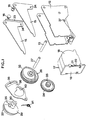
- Fig. 1 is an exploded view showing parts of an embodiment of a stapler according to the invention, in perspective;
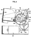
- Figs 2-5 are longitudinal sections showing the stapler in different stapling positions; and
- Fig. 6 is a view showing parts of a cam mechanism.
- The illustrated stapler is electrically operated and comprises a
fixed base 11 and astapler head 12 pivotably connected to thebase 11. Thestapler head 12 is pivotable about atransverse pin 13 between an upper starting position (shown in Fig. 2) and a lower working position (shown in Figs 3 and 4), in which it is applied against a sheaf ofpapers 14 placed in the stapler between thebase 11 and thestapler head 12. Thus, the working position of thestapler head 12 depends on the thickness of the sheaf ofpapers 14. - The
stapler head 12 is a U-shaped channel (see Fig. 1) in which there is provided a drive mechanism in the form of twoarms 15. At the rear ends, thearms 15 are each pivotably connected to a side wall of the U-shaped channel. Thearms 15 extend forwards in parallel with the side walls and project, at the front ends, a certain distance beyond thestapler head 12. Thearms 15 are each pivotable about atransverse pivot pin 16 fixed to a channel side wall. Thepivot pins 16 are located opposite to one another and are parallel to thepin 13. Thearms 15 are pivotable in relation to thestapler head 12 between an upper turning position (indicated by thin lines in Fig. 4) and a lower turning position (indicated by thick lines in Fig. 5). - A
magazine 17 containing staple blanks (not shown) is mounted in the front portion of thestapler hand 12. In this case, the magazine is a cassette of the type described in SE Patent Application 9201230-1 (SE-B-469112). Thecassette 17 has acasing 18 containing straight wire blanks which are juxtaposed and releasably interconnected to form a strip of staple blanks, which is rolled up into a roll (not shown). Thecassette 17 also has afront plate 19, in which astaple shaper 20 and astaple driver 21 are arranged in reciprocating fashion. At the front portions, thearms 15 engage thestaple shaper 20 and thestaple driver 21 so as to reciprocate these upwards and downwards during their pivotal movements. When thearms 15 are being swung downwards, thestaple shaper 20 and thestaple driver 21 are moved downwards, and thestaple shaper 20 bends a staple blank into a U-shaped staple while thestaple driver 21 releases the U-shaped staple formed by thestaple shaper 20 during the preceding stapling cycle and drives it into the sheaf ofpapers 14. Naturally, this takes place when thestapler head 12 is in its working position, i.e. applied against the sheaf ofpapers 14. - As mentioned in the foregoing, the stapler is electrically operated, and is driven by an
electric motor 22 provided in thebase 11. Via aworm gear 24, theoutput shaft 23 of themotor 22 drives adriving gear wheel 25. Thewheel 25 is rotatably mounted on thepin 13 which is connected to thebase 11 and about which the stapler head 12 pivots. Thedriving gear wheel 25 is adapted to drive acam mechanism 26 provided in thestapler head 12 and rotatably mounted on apin 27 which is parallel to thepin 13 and connected to the stapler head. To this end, thedriving gear wheel 25 meshes with agear wheel 28 forming part of thecam mechanism 26 and mounted on thepin 27. In addition to thegear wheel 28, thecam mechanism 26 includes acam wheel 29 which is non-rotatably connected to thegear wheel 28. Thegear wheel 28 and thecam wheel 29 are interconnected by ahub portion 30 which is provided on thecam wheel 29 and has a non-circular cross-section and which is inserted in a centre hole provided in thegear wheel 28 and having a corresponding cross-sectional shape. - The
gear wheel 28 and thecam wheel 29 each have a closedcam curve 32 with a cam surface facing radially outwards and a cam surface facing radially inwards. Thecam curves 32 are identical and cooperate with therespective arms 15 so as to pivot, when thecam mechanism 26 rotates, thearms 15 in synchronised fashion between the upper turning positions and the lower turning positions. The outward cam surface then cooperates with arear flange 33 on therespective arms 15, while the inward cam surface cooperates with apin 34 connected to therespective arms 15 and located slightly ahead of theflange 33. - The
hub portion 30 has a cam means 35, non-rotatably connected thereto, of pear-like cross-sectional shape. The cam means 35 has a first portion which extends throughout most of its circumference and has a constant radius with respect to thepin 27, as well as second portion which extends throughout a much smaller part of its circumference and also has a constant radius. As appears from Figs 2-5, the radius of the second portion is much larger than that of the first portion. - A
locking plate 36 parallel to the side walls of thestapler head 12 is pivotably connected to thestapler head 12. Thelocking plate 36 is pivotable about apin 37 parallel to thepins stapler head 12 at a considerable distance ahead of thepivot pin 13 of thestapler head 12. Also, thelocking plate 36 has anarcuate slot 38 in which engages alocking pin 39 parallel to thepins locking pin 39 is fixedly connected to thebase 11 at the upper rear portion thereof (behind and above the pin 13). At the centre, thelocking plate 36 has ahole 40 of a special shape. Thehub portion 30 of thecam mechanism 26 extends through thehole 40, and the cam means 35 on thehub portion 30 is located axially opposite to thelocking plate 36 so as to cooperate with the boundary wall of thehole 40, as shown in Figs 2-5. - The
locking plate 36 is pivotable between an upper first position (shown in Fig. 2) in which thelocking pin 39 is located in a lower end portion of thearcuate slot 38, and a lower second position (shown in Figs 3 and 4) which depends on the thickness of the sheaf ofpapers 14 and in which thelocking pin 39 is located in an intermediary portion of thearcuate slot 38. Thelocking plate 36 is biased towards the second position by aspring 41 mounted on thepin 37 between the bottom of thestapler head 12 and the front edge of thelocking plate 36. With respect to thepin 37, thearcuate slot 38 has a radius of curvature increasing in the direction away from the lower end portion towards the upper end portion. First, the radius of curvature increases considerably throughout a small part of the length of theslot 38, and then increases slowly throughout the remainder of the slot length. The reason for this will be explained in more detail below. - The function of the stapler will now be described in more detail with reference to Figs 2-6.
- In the starting position (Fig. 2), the
stapler head 12 is in its upper position and thecam mechanism 26 occupies such a rotational position that thecam curves 32 maintain thearms 15 in an intermediary position between the two turning positions and that the large-radius second portion of thecam means 35 is applied against aprojection 42 on the boundary wall surrounding thehole 40 in thelocking plate 36 and maintains thelocking plate 36 in its upper first position, so that thespring 41 is unable to urge thelocking plate 36 to its lower second position. - When a sheaf of
papers 14 is placed in the stapler, a microswitch (not shown) is actuated and starts themotor 22. Then, themotor 22 rotates thegear wheel 28, which meshes with thedriving gear wheel 25, and consequently theentire cam mechanism 26, one turn anticlockwise with respect to Figs 2-6. When thecam mechanism 26, and hence the cam means 35, has been turned slightly, the cam means releases thelocking plate 36, which then is moved to its lower second position (Fig. 3) by thespring 41. Since thearcuate slot 38 has a radius of curvature increasing in the direction away from the lower end portion towards the upper end portion with respect to thepin 37, the distance between thelocking pin 39 and thepin 37 has to increase while thelocking plate 36 is swung downwards. This increase in distance is achieved by thepin 37, connected to thestapler head 12, pivoting the stapler head 12 downwards to its working position (Fig. 3). Since thelocking pin 39, during the pivotal movement of thelocking plate 36 from the upper first position to the lower second position, first passes the short slot portion where the increase in radius of curvature is considerable, thestapler head 12 is initially swung downwards quite rapidly. This rapid downward movement takes place in an area where thestapler head 12 does not run the risk of hitting a sheaf ofpapers 14, i.e. in an area located above the thickest sheaf that can be placed in the stapler. - The
stapler head 12 is locked in its working position since it cannot be swung upwards about thepivot pin 13 because the increase of the radius of curvature of thearcuate slot 38 is so chosen with respect to the material (preferably hardened steel) of which thelocking plate 36 and thelocking pin 39 are made, that a locking wedge action occurs between the wall of theslot 38 and thelocking pin 39. - During the initial rotation of the
cam mechanism 26, the cam curves 32 are applied against thepins 34 of therespective arms 15 by a circumferential portion C1 of the cam surface that faces radially inwards. The circumferential portion C1 has a decreasing radius with respect to thepin 27 in order to swing thearms 15 to their upper turning positions in cooperation with the respective pins 34. The circumferential portion C1 has an extent of about 95°. When thestapler head 12 reaches the sheaf of papers 14 (Fig. 3), thearms 15 are thus being swung upwards. - When the
cam mechanism 26 is further rotated, the cam curves 32 come to be applied against theflanges 33 of therespective arms 15 by a circumferential portion C2 of the cam surface that faces radially outwards. The circumferential portion C2 has a slightly increasing radius with respect to thepin 27 and an extent of about 100°. When thecam mechanism 26 is further rotated, thearms 15 are thus swung downwards to a lower position (indicated by thick lines in Fig. 4) in which they have moved thestaple shaper 20 and thestaple driver 21 to lower positions, which means that thestaple driver 21 is located quite near the uppermost sheet of paper of thesheaf 14 after having driven a staple into it and that thestaple shaper 20 has begun bending of the following staple blank. - When the
cam mechanism 26 is further rotated, the cam curves 32 come to be applied against theflanges 33 of therespective arms 15 by a circumferential portion C3 of the cam surface that faces radially outwards. The circumferential portion C3 has a constant radius in order to retain thearms 15, and hence thestaple shaper 20 and thestaple driver 21, in their lower positions during a clinching operation (not described in detail here) for bending the legs of the inserted staple against the underside of the sheaf ofpapers 14. The circumferential portion C3 has an extent of about 20° and merges into a circumferential portion C4 of the cam surface that faces radially outwards. Also the circumferential portion C4 has a constant radius so as to retain thearms 15, and hence thestaple shaper 20 and thestaple driver 21, in their lower positions. The circumferential portion C4 has an extent of about 50°. - In the phase when the
arms 15 are retained in their lower positions by the circumferential portion C4, the large-radius second portion of the cam means 35 hits theprojection 42 and pivots the lockingplate 36 back to its upper first position against the action of thespring 41. Thestapler head 12 is thus swung to its upper position as a result of the decrease of the radius of curvature of thearcuate slot 38 in the direction away from its upper end portion towards its lower end portion. - While the
stapler head 12 is thus swung back to its upper position, the cam curves 32 come to be applied against theflanges 33 of therespective arms 15 by a circumferential portion C5 of the cam surface that faces radially outwards. The circumferential portion C5 has a slightly increasing radius with respect to thepin 27 so as to pivot thearms 15 to their lower turning positions (indicated by thick lines in Fig. 5). The circumferential portion C5 has an extent of about 20°. When thearms 15 occupy their lower turning positions, thestaple shaper 20 has completed bending of the staple blank and thestaple driver 21 occupies a position in which it projects from thestapler head 12. When thestaple driver 21 performs this prolonged stroke in the driving direction, i.e. moves from the lower position shown in Fig. 4 to the lower turning position shown in Fig. 5, it can expel a staple that for some reason has not been driven into the sheaf of papers during the driving stroke, but has been deformed and got stuck in thestapler head 12. - In the final phase of the revolution of the
cam mechanism 26, the cam curves 32 come to be applied against thepins 34 of therespective arms 15 by a circumferential portion C6 of the cam surface that faces radially inwards. The circumferential portion C6 has a decreasing radius with respect to thepin 27 so as to pivot thearms 15 towards their upper turning positions (indicated by thin lines in Fig. 4). The circumferential portion C6 has an extent of about 40° and merges into the circumferential portion C1, which pivots thearms 15 further upwards, as described above. The transition between the circumferential portion C6 and the circumferential portion C1 corresponds to the starting position illustrated in Fig. 2.
Claims (1)
- A stapler for driving staples into an object (14), such as a sheaf of papers, said stapler comprising a base (11), a stapler head (12) pivotably connected to the base via a first pin (13) and pivotable between a starting position and a working position, in which it is applied against said object when this is placed in the stapler between the stapler head and the base, the stapler head (12) being adapted to accommodate wire staple blanks which are juxtaposed and releasably interconnected to form at least one strip of staple blanks, a reciprocating staple shaper (20) arranged in the stapler head (12) to successively shape the staple blanks of the strip into substantially U-shaped staples, a reciprocating staple driver (21) arranged in the stapler head (12) to successively release the thus-formed staples from the strip and drive them into said object (14), an operating means (15) which is pivotable about a second pin (16) parallel to the first pin (13) and which is adapted to reciprocate the staple shaper (20) and the staple driver (21), and a drive means (22-26) adapted to pivot the stapler head (12) and the operating means (15) in synchronism such that the operating means (15) causes the staple driver (21), in a driving stroke, to drive a staple into said object and causes the staple shaper (20), in a shaping stroke, to shape the following staple, and such that the stapler head (12) is pivoted to its working position before the staple driver (21) performs the driving stroke, and is retained there during the driving stroke of the staple driver, characterised in that the drive means (22-26) is adapted to synchronise the pivotal movements of the stapler head (12) and the operating means (15) in such a manner that the staple driver (21) performs a prolonged stroke in the driving direction and the staple shaper (20) performs the last phase of the shaping stroke when the stapler head (12) has left its working position in order to be pivoted back to its starting position.
Applications Claiming Priority (3)
| Application Number | Priority Date | Filing Date | Title |
|---|---|---|---|
| SE9301873 | 1993-06-02 | ||
| SE9301873A SE9301873L (en) | 1993-06-02 | 1993-06-02 | Stapler for collecting staples |
| PCT/SE1994/000470 WO1994027788A1 (en) | 1993-06-02 | 1994-05-20 | Stapler |
Publications (2)
| Publication Number | Publication Date |
|---|---|
| EP0701500A1 EP0701500A1 (en) | 1996-03-20 |
| EP0701500B1 true EP0701500B1 (en) | 1997-07-16 |
Family
ID=20390128
Family Applications (1)
| Application Number | Title | Priority Date | Filing Date |
|---|---|---|---|
| EP94917852A Expired - Lifetime EP0701500B1 (en) | 1993-06-02 | 1994-05-20 | Stapler |
Country Status (8)
| Country | Link |
|---|---|
| US (1) | US5660314A (en) |
| EP (1) | EP0701500B1 (en) |
| JP (1) | JP2647265B2 (en) |
| CN (1) | CN1042507C (en) |
| AU (1) | AU6939594A (en) |
| DE (1) | DE69404309T2 (en) |
| SE (1) | SE9301873L (en) |
| WO (1) | WO1994027788A1 (en) |
Families Citing this family (16)
| Publication number | Priority date | Publication date | Assignee | Title |
|---|---|---|---|---|
| JPH10236014A (en) * | 1997-02-26 | 1998-09-08 | Max Co Ltd | Device for tying stacked body |
| US6135337A (en) * | 1999-01-15 | 2000-10-24 | Hunt Holdings, Inc. | Electric stapler |
| US6536646B1 (en) * | 2000-02-22 | 2003-03-25 | Acco Brands, Inc. | Stapler |
| JP3657174B2 (en) | 2000-06-05 | 2005-06-08 | ニスカ株式会社 | Staple device |
| JP4514286B2 (en) | 2000-06-05 | 2010-07-28 | ニスカ株式会社 | Staple needle storage cartridge |
| JP2001347472A (en) | 2000-06-05 | 2001-12-18 | Nisca Corp | Stapler device |
| JP4524868B2 (en) * | 2000-06-21 | 2010-08-18 | マックス株式会社 | Electric stapler |
| JP4784020B2 (en) * | 2001-08-23 | 2011-09-28 | マックス株式会社 | Staple detection mechanism in electric stapler |
| JP4239732B2 (en) * | 2003-07-07 | 2009-03-18 | マックス株式会社 | Electric stapler drive mechanism |
| JP4513484B2 (en) * | 2004-09-29 | 2010-07-28 | マックス株式会社 | Stapler table lock device |
| CN2815700Y (en) * | 2005-09-01 | 2006-09-13 | 煜日升电子(深圳)有限公司 | Electric book binding machine |
| JP6022578B2 (en) * | 2011-09-13 | 2016-11-09 | イサベルク・ラピッド・エービーIsaberg Rapid Ab | Mechanism for correction of bundle thickness in the stapler |
| JP5772490B2 (en) * | 2011-10-20 | 2015-09-02 | マックス株式会社 | Electric stapler |
| US9522463B2 (en) * | 2012-07-25 | 2016-12-20 | Worktools Inc. | Compact electric spring energized desktop stapler |
| US10255907B2 (en) | 2015-06-07 | 2019-04-09 | Apple Inc. | Automatic accent detection using acoustic models |
| JP7830850B2 (en) * | 2021-07-30 | 2026-03-17 | マックス株式会社 | stapler |
Family Cites Families (5)
| Publication number | Priority date | Publication date | Assignee | Title |
|---|---|---|---|---|
| US4623082A (en) * | 1985-05-14 | 1986-11-18 | Max Co. Ltd. | Electronic stapler |
| JPS62236684A (en) * | 1986-04-08 | 1987-10-16 | 丸善株式会社 | Electric stapler |
| US5230457A (en) * | 1987-11-16 | 1993-07-27 | Canon Kabushiki Kaisha | Sheet stapler |
| US5195671A (en) * | 1989-11-17 | 1993-03-23 | Matsushita Electric Industrial Co., Ltd. | Stapler |
| SE9201231L (en) * | 1992-04-16 | 1993-05-17 | Isaberg Ab | STAPLES FOR RECOVERY OF STAMPS |
-
1993
- 1993-06-02 SE SE9301873A patent/SE9301873L/en unknown
-
1994
- 1994-05-20 EP EP94917852A patent/EP0701500B1/en not_active Expired - Lifetime
- 1994-05-20 WO PCT/SE1994/000470 patent/WO1994027788A1/en not_active Ceased
- 1994-05-20 AU AU69395/94A patent/AU6939594A/en not_active Abandoned
- 1994-05-20 JP JP7500532A patent/JP2647265B2/en not_active Expired - Lifetime
- 1994-05-20 DE DE69404309T patent/DE69404309T2/en not_active Expired - Fee Related
- 1994-05-20 US US08/549,703 patent/US5660314A/en not_active Expired - Lifetime
- 1994-05-20 CN CN94192331A patent/CN1042507C/en not_active Expired - Fee Related
Also Published As
| Publication number | Publication date |
|---|---|
| CN1042507C (en) | 1999-03-17 |
| SE9301873D0 (en) | 1993-06-02 |
| US5660314A (en) | 1997-08-26 |
| JP2647265B2 (en) | 1997-08-27 |
| WO1994027788A1 (en) | 1994-12-08 |
| AU6939594A (en) | 1994-12-20 |
| CN1124938A (en) | 1996-06-19 |
| SE500252C2 (en) | 1994-05-24 |
| DE69404309D1 (en) | 1997-08-21 |
| DE69404309T2 (en) | 1997-10-30 |
| JPH08507975A (en) | 1996-08-27 |
| EP0701500A1 (en) | 1996-03-20 |
| SE9301873L (en) | 1994-05-24 |
Similar Documents
| Publication | Publication Date | Title |
|---|---|---|
| US5660314A (en) | Stapler | |
| JP3598765B2 (en) | Staple clinch mechanism in stapler | |
| EP0636059B1 (en) | Stapler | |
| US5516025A (en) | Stapler having a clinching mechanism | |
| JP4590694B2 (en) | Booster mechanism of stapler | |
| US7044349B2 (en) | Stapler for forming staples to various sizes | |
| US6981627B2 (en) | Electric stapler having an apparatus to bend staple legs and the apparatus | |
| JPH0585358B2 (en) | ||
| EP0027336B1 (en) | Passive clincher and stapler incorporating same | |
| US6702172B1 (en) | Staple driver with convex edge and pointed protrusions at the ends | |
| WO1998047669A1 (en) | Stapler with internal guidance of the legs of a staple | |
| EP1220737B1 (en) | Stapler for forming staples to various sizes | |
| US6592115B2 (en) | Stapler with single driving source | |
| JP4110854B2 (en) | Electric stapler | |
| EP0597782A1 (en) | A power stapler | |
| JP3503368B2 (en) | Electric stapler staple leg cutting mechanism | |
| WO2005014237A1 (en) | Locking mechanism for stapler paper presser table | |
| WO2005068135A1 (en) | Stapler | |
| JP4036215B2 (en) | Electric stapler | |
| JPH0335084B2 (en) | ||
| US6739492B1 (en) | Stapler for forming staples to various sizes | |
| JP4232716B2 (en) | Stapler cartridge | |
| WO2002049817A1 (en) | Stapler for forming staples to various sizes | |
| JPH0970768A (en) | Clinch mechanism in stapler | |
| JPH0653074U (en) | Stapler |
Legal Events
| Date | Code | Title | Description |
|---|---|---|---|
| PUAI | Public reference made under article 153(3) epc to a published international application that has entered the european phase |
Free format text: ORIGINAL CODE: 0009012 |
|
| 17P | Request for examination filed |
Effective date: 19951110 |
|
| AK | Designated contracting states |
Kind code of ref document: A1 Designated state(s): DE FR GB |
|
| GRAG | Despatch of communication of intention to grant |
Free format text: ORIGINAL CODE: EPIDOS AGRA |
|
| GRAH | Despatch of communication of intention to grant a patent |
Free format text: ORIGINAL CODE: EPIDOS IGRA |
|
| 17Q | First examination report despatched |
Effective date: 19961024 |
|
| GRAH | Despatch of communication of intention to grant a patent |
Free format text: ORIGINAL CODE: EPIDOS IGRA |
|
| RAP1 | Party data changed (applicant data changed or rights of an application transferred) |
Owner name: ISABERG RAPID AB |
|
| GRAA | (expected) grant |
Free format text: ORIGINAL CODE: 0009210 |
|
| AK | Designated contracting states |
Kind code of ref document: B1 Designated state(s): DE FR GB |
|
| PG25 | Lapsed in a contracting state [announced via postgrant information from national office to epo] |
Ref country code: FR Effective date: 19970716 |
|
| REF | Corresponds to: |
Ref document number: 69404309 Country of ref document: DE Date of ref document: 19970821 |
|
| EN | Fr: translation not filed | ||
| PLBE | No opposition filed within time limit |
Free format text: ORIGINAL CODE: 0009261 |
|
| STAA | Information on the status of an ep patent application or granted ep patent |
Free format text: STATUS: NO OPPOSITION FILED WITHIN TIME LIMIT |
|
| 26N | No opposition filed | ||
| REG | Reference to a national code |
Ref country code: GB Ref legal event code: IF02 |
|
| PGFP | Annual fee paid to national office [announced via postgrant information from national office to epo] |
Ref country code: DE Payment date: 20080508 Year of fee payment: 15 |
|
| PGFP | Annual fee paid to national office [announced via postgrant information from national office to epo] |
Ref country code: GB Payment date: 20080508 Year of fee payment: 15 |
|
| GBPC | Gb: european patent ceased through non-payment of renewal fee |
Effective date: 20090520 |
|
| PG25 | Lapsed in a contracting state [announced via postgrant information from national office to epo] |
Ref country code: GB Free format text: LAPSE BECAUSE OF NON-PAYMENT OF DUE FEES Effective date: 20090520 |
|
| PG25 | Lapsed in a contracting state [announced via postgrant information from national office to epo] |
Ref country code: DE Free format text: LAPSE BECAUSE OF NON-PAYMENT OF DUE FEES Effective date: 20091201 |