EP0701388A2 - Improvement in a humidity measurement arrangement and cooking oven provided therewith - Google Patents
Improvement in a humidity measurement arrangement and cooking oven provided therewith Download PDFInfo
- Publication number
- EP0701388A2 EP0701388A2 EP95111507A EP95111507A EP0701388A2 EP 0701388 A2 EP0701388 A2 EP 0701388A2 EP 95111507 A EP95111507 A EP 95111507A EP 95111507 A EP95111507 A EP 95111507A EP 0701388 A2 EP0701388 A2 EP 0701388A2
- Authority
- EP
- European Patent Office
- Prior art keywords
- cooking cavity
- cooking
- oven
- oven according
- probe
- Prior art date
- Legal status (The legal status is an assumption and is not a legal conclusion. Google has not performed a legal analysis and makes no representation as to the accuracy of the status listed.)
- Granted
Links
Images


Classifications
-
- H—ELECTRICITY
- H05—ELECTRIC TECHNIQUES NOT OTHERWISE PROVIDED FOR
- H05B—ELECTRIC HEATING; ELECTRIC LIGHT SOURCES NOT OTHERWISE PROVIDED FOR; CIRCUIT ARRANGEMENTS FOR ELECTRIC LIGHT SOURCES, IN GENERAL
- H05B6/00—Heating by electric, magnetic or electromagnetic fields
- H05B6/64—Heating using microwaves
- H05B6/6447—Method of operation or details of the microwave heating apparatus related to the use of detectors or sensors
- H05B6/6458—Method of operation or details of the microwave heating apparatus related to the use of detectors or sensors using humidity or vapor sensors
-
- A—HUMAN NECESSITIES
- A21—BAKING; EDIBLE DOUGHS
- A21B—BAKERS' OVENS; MACHINES OR EQUIPMENT FOR BAKING
- A21B3/00—Parts or accessories of ovens
- A21B3/04—Air-treatment devices for ovens, e.g. regulating humidity
-
- H—ELECTRICITY
- H05—ELECTRIC TECHNIQUES NOT OTHERWISE PROVIDED FOR
- H05B—ELECTRIC HEATING; ELECTRIC LIGHT SOURCES NOT OTHERWISE PROVIDED FOR; CIRCUIT ARRANGEMENTS FOR ELECTRIC LIGHT SOURCES, IN GENERAL
- H05B6/00—Heating by electric, magnetic or electromagnetic fields
- H05B6/64—Heating using microwaves
- H05B6/647—Aspects related to microwave heating combined with other heating techniques
- H05B6/6473—Aspects related to microwave heating combined with other heating techniques combined with convection heating
Definitions
- the present invention refers to a cooking oven, in particular such an oven for cooking food, provided with a moisture measurement arrangement so as to enable the degree of humidity in the cooking cavity to be automatically adjusted to the pre-set level during food cooking processes.
- a cooking oven in particular such an oven for cooking food
- a moisture measurement arrangement so as to enable the degree of humidity in the cooking cavity to be automatically adjusted to the pre-set level during food cooking processes.
- Food cooking ovens are already known which are substantially formed by a box-like casing defining an inner cooking cavity in which the food to be cooked is properly arranged, a forced-draft hot air circulation being generated in said cooking cavity by means of a gas-fired or electric heat generator and at least a fan.
- thermostatic control means being associated with corresponding temperature selection means which are adjusted by the user on the desired temperature setting before each cooking process is started, in accordance with the type and the amount of food to be cooked.
- thermostatic temperature control means of these ovens operate in such a manner as to keep the cooking temperature within pre-determined limits inside the cooking cavity of the oven, generally by cyclically switching on and off both the heat generator and/or the possibly provided steam generator, if the oven is designed to also cook by steam, and the fan so as to appropriately vary the flow of hot air circulating through the cooking cavity.
- humidity control and measurement devices are known in connection with a number of applications of different kind and they are generally constituted by semiconductor-type sensors, which are arranged in the humid rooms or compartments to be controlled and are connected with electric bridge-like measurement circuits that are adapted to detect the corresponding electric signals generated by said sensors so as to automatically convert them into respective levels of humidity in the room being measured.
- Still other types of moisture measurement arrangements are constituted by elements for measuring the concentration of oxygen in gaseous mixtures, such as for instance zirconium-oxide cells, operating according to well-known principles.
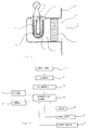
- FIG 1 this is shown to illustrate the interior of the cooking cavity of a food cooking oven for professional kitchens, comprising a motor-driven fan 1 arranged on the rear side of said cooking cavity, as well as appropriate arrangements (not shown) to generate and propagate microwaves inside said cooking cavity, for instance of the type described in the European patent application no. 90119715 filed by the same applicant.
- the food contained in said cooking cavity may be processed in a number of different ways, such as for instance by forced-draft circulation of hot air produced by suitable gas-fired or electric heat generating means (not shown) of some per sè known type, by steaming or by a combination of steaming and forced-convection hot air, or even by microwaves alone or combined with forced-convection hot air and/or steam.
- suitable gas-fired or electric heat generating means not shown
- steaming or by a combination of steaming and forced-convection hot air or even by microwaves alone or combined with forced-convection hot air and/or steam.
- the oven being considered also comprises the humidity measurement arrangement 3 according to the present invention, which is shown to be housed in the cooking cavity 2 and is arranged to operate in the way that will be described below.
- Such an arrangement is substantially constituted by probe means adapted to measure the partial pressure of oxygen inside the cooking cavity with respect to the external environment, said probe means being appropriately arranged and insulated to exclude any interference by the other gases being present in the cooking cavity, and it is common knowledge that, based on such a measurement, the value of the humidity prevailing in the cooking cavity can then be inferred.
- a zirconium-oxide based probe for detecting oxygen concentrations is generally constituted by a cell which features a pair of electrodes (usually of platinum) applied thereto, and which is kept at a constant temperature T (normally 350°C).
- a measurement of the concentration of oxygen enables the percentage of a third gas, ie. water vapour in this particular case, to be determined directly when it is added to a sample of the air being measured.
- a third gas added to a sample of air has the effect of reducing in a proportional manner the presence of oxygen and nitrogen in the sample, as this is best shown in Figure 5.
- determining the relative concentration of oxygen in such a sample, or in a particular room which was originally filled only with air ie. such as the interior of a cooking cavity at the beginning of the cooking process, allows the amount of gases, such as water vapour, introduced in and differing from the original components of the mixture to be determined as well.
- the oven may further be provided with a boiler 4 for steam generation purposes, as well as an appropriate conduit 5 for delivering said steam from the boiler 4 to the cooking cavity 2.
- the oven may be additionally provided also with a flue riser 6 for exhausting flue gases and excess vapours, as well as a venting shutter 7 for shutting said flue riser to the purpose of adjusting the internal atmosphere in the oven cavity; it may be further provided with a conduit 8 for letting in water against the blades of the fan 1 provided to ensure forced-draft circulation of the hot air, so as to produce an atomization effect when it comes into contact with the heating elements, as well as with a corresponding shut-off valve 9 associated with said conduit 8.
- a drain conduit 10 is connected to the bottom of said cooking cavity so as to enable residual liquids, such as fat, water and other cooking by-products, to be conveniently removed therefrom.
- the present invention consists in providing a cooking oven with a humidity measurement arrangement as described, and adapting both said arrangement 3 and the cooking oven to a mutually compatible operation so as to optimize the performance capabilities of the same oven.
- the humidity measurement arrangement 3 consists substantially of:
- This arrangement is accomodated in a recess 15 provided, preferably by press forming, in a wall 16 of the cooking cavity of the oven.
- the arrangement also comprises a surface of porous platinum 17 having a sealed tubular form which, like the afore cited electrode 10, acts as a catalytic-effect electrode to amplify the electromotive force that is generated owing to the difference between the partial pressure of the oxygen in the ambient air and the one in the cooking cavity.
- a protective baffle 14 with fat and soil retaining properties be removably provided at the entrance 13 of the recess 11 that houses the probe.
- the slits M1 and M2 through which said hollow spaces open towards the interior of the cooking cavity are provided to enable steam to diffuse so as to reach the probe.
- the lower slit M2 serves additionally the purpose of ensuring draining of washing or condensation liquids that seep through the other slit M1.
- said cover is arranged in such a way that said slits M1 and M2 are flush with the wall so as to avoid affecting the air flow generated by the fan arrangement; furthermore, it is oriented in such a manner that the slits are arranged orthogonally with respect to the air flow R which is generally conveying fat and other soil particles that may occlude the probe.
- said particles tend to follow the trajectory R without penetrating into the slits, whereas humidity diffuses quickly into the hollow space 32 and, from there, into the interior of the recess 15, until it reaches the probe, even without being assisted by an air circulation.
- a labyrinth-type filter which may for instance be constituted by a plurality of walls 33, 34 which would force the air flow to follow a path extending partly backwards between the entrance 13 of the recess and the probe, so as to stop it.
- such a filter is made, so as most clearly illustrated in Figure 8, so that the preferential air-circulation path S inside it is orthogonal with respect to the direction of the air flow coming from the hollow space 32 and making its way into the recess 15, thereby maximizing its stoppage effect.
- the flow-chart illustrating the operation of the various members is shown in the form of a block diagram in Figure 4, where it can be seen that the arrangement 3, which may be defined as a lambda probe in accordance with international conventions designating the lambda excess air factor as the ratio of the value being examined to the stoichiometric value of the combustion air, is connected to a voltage meter 21 supplying an analog/digital voltage converter 22 which in turn sends the converted signal to an appropriately programmed processing and control means 23 which is adapted to both supply an appropriately provided display 24 on the outside of the oven with signals indicative of the detected humidity contents in the oven cavity, and receive humidity-degree signals as set through appropriate adjusting means 25.
- the arrangement 3 which may be defined as a lambda probe in accordance with international conventions designating the lambda excess air factor as the ratio of the value being examined to the stoichiometric value of the combustion air, is connected to a voltage meter 21 supplying an analog/digital voltage converter 22 which in turn sends the converted signal to an appropriately programme
- a particularly advantageous opportunity created by such a function lies in the possibility of said processing and control means 23 to automatically adjust the humidity inside the cooking cavity of the oven to the pre-set value by constantly processing and comparing said pre-set value with the value being detected by the measurement arrangement 3, and then controlling with any of a number of well-known state-of-art techniques the operation of the boiler 4, the water inlet valve 9 and the venting shutter 7 accordingly, so as to automatically attain and maintain said pre-set value.
- the oven is of course provided with a number of further elements and arrangements which, owing to their not being an object of the present invention, are omitted.
Abstract
Description
- The present invention refers to a cooking oven, in particular such an oven for cooking food, provided with a moisture measurement arrangement so as to enable the degree of humidity in the cooking cavity to be automatically adjusted to the pre-set level during food cooking processes. In the following description of the present invention reference is made in particular to an oven for cooking food in catering or foodservice establishments. It will however be appreciated that what is described and claimed here equally applies to any other type of food cooking ovens.
- Food cooking ovens are already known which are substantially formed by a box-like casing defining an inner cooking cavity in which the food to be cooked is properly arranged, a forced-draft hot air circulation being generated in said cooking cavity by means of a gas-fired or electric heat generator and at least a fan.
- These food cooking ovens are provided with appropriate thermostatically operating arrangements for automatic adjustment of the selected food cooking temperature, these thermostatic control means being associated with corresponding temperature selection means which are adjusted by the user on the desired temperature setting before each cooking process is started, in accordance with the type and the amount of food to be cooked.
- The thermostatic temperature control means of these ovens operate in such a manner as to keep the cooking temperature within pre-determined limits inside the cooking cavity of the oven, generally by cyclically switching on and off both the heat generator and/or the possibly provided steam generator, if the oven is designed to also cook by steam, and the fan so as to appropriately vary the flow of hot air circulating through the cooking cavity.
- These cooking ovens, however, are not provided with any arrangement for adjusting the humidity of the air inside the cooking cavity, such a humidity of the air being in this case a factor that, combined with the temperature, decisively affects both the quality of the cooking process as a whole and the taste of the food being cooked, since said humidity is variable depending on a number of parameters of the cooking process such as the cooking temperature, the type and the actual amount of food to be cooked, the replacement rate of the air in the cooking cavity, and so on, so that these appliances are actually unable to ensure such optimum food cooking results as they on the other hand certainly would in a most desirable manner, under the same performance conditions, if such a humidity adjustment function could be carried out in the process.
- On the other hand, humidity control and measurement devices are known in connection with a number of applications of different kind and they are generally constituted by semiconductor-type sensors, which are arranged in the humid rooms or compartments to be controlled and are connected with electric bridge-like measurement circuits that are adapted to detect the corresponding electric signals generated by said sensors so as to automatically convert them into respective levels of humidity in the room being measured.
- Still other types of moisture measurement arrangements are constituted by elements for measuring the concentration of oxygen in gaseous mixtures, such as for instance zirconium-oxide cells, operating according to well-known principles.
- However, all such humidity measurement devices and arrangements, while ensuring accurate and correct measurement results, are generally poorly suited to applications involving the measurement of humidity in a food cooking environment, where temperatures prevail that may be situated anywhere between approx. 100°C and 250°C according to the type and the amount of food to be cooked, since the devices would in the first case become damaged, and therefore would be unable to correctly perform their duty any longer, and, in the second case, they would not be in a position to ensure a reliable operation any further, due to their sensing elements being subject to soiling under alteration of the related measurement values.
- It is therefore a purpose of the present invention to overcome the drawbacks and the limitations of the afore cited humidity measurement devices and arrangements by providing a humidity measurement arrangement referring to a food cooking oven according to the appended claims and the following description which is given by way of non-limiting example with reference to the accompanying drawing, in which:
- Figure 1 is a vertical, half-depth cross-sectional view showing schematically a food cooking oven according to the present invention;
- Figure 2 is a horizontal, cross-sectional view of the oven illustrated in Figure 1;
- Figure 3 is a view of a construction detail of the humidity measurement arrangement according to the present invention;
- Figure 4 is a block flow-chart of an operation sequence of the oven according to the present invention;
- Figure 5 is a diagram of the composition of a gas mixture, composed by air and water vapour, versus the percentage of air;
- Figure 6 is a vertical, half-depth cross-sectional view of a cooking oven according to an improved embodiment of the present invention;
- Figures 7 and 8 are an enlarged view of a front section and a horizontal section, respectively, of the improved embodiment illustrated in Figure 6.
- Referring now to Figure 1, this is shown to illustrate the interior of the cooking cavity of a food cooking oven for professional kitchens, comprising a motor-driven
fan 1 arranged on the rear side of said cooking cavity, as well as appropriate arrangements (not shown) to generate and propagate microwaves inside said cooking cavity, for instance of the type described in the European patent application no. 90119715 filed by the same applicant. - The food contained in said cooking cavity may be processed in a number of different ways, such as for instance by forced-draft circulation of hot air produced by suitable gas-fired or electric heat generating means (not shown) of some per sè known type, by steaming or by a combination of steaming and forced-convection hot air, or even by microwaves alone or combined with forced-convection hot air and/or steam.
- The oven being considered also comprises the
humidity measurement arrangement 3 according to the present invention, which is shown to be housed in thecooking cavity 2 and is arranged to operate in the way that will be described below. - Such an arrangement is substantially constituted by probe means adapted to measure the partial pressure of oxygen inside the cooking cavity with respect to the external environment, said probe means being appropriately arranged and insulated to exclude any interference by the other gases being present in the cooking cavity, and it is common knowledge that, based on such a measurement, the value of the humidity prevailing in the cooking cavity can then be inferred.
- To mere informatory purposes, the state of the art in this particular field is briefly recalled here: a zirconium-oxide based probe for detecting oxygen concentrations is generally constituted by a cell which features a pair of electrodes (usually of platinum) applied thereto, and which is kept at a constant temperature T (normally 350°C).
- "Reference air" with a known and constant oxygen concentration is delivered on one of the two sides of the cell. By measuring with a suitable millivoltmeter the electromotive force of the cell, a direct indication of the concentration of oxygen in contact with the cell, on the "measurement" side thereof, is obtained.
- The above described method has for instance found a wide application in the measurement of oxygen concentrations in flue gases.
- On the other hand, it may be also used advantageously for measuring humidity in high-temperature air-steam mixtures.
- Based on the assumption that the oxygen/nitrogen ratio in the air is constant, a measurement of the concentration of oxygen enables the percentage of a third gas, ie. water vapour in this particular case, to be determined directly when it is added to a sample of the air being measured. In fact, the presence of a third gas added to a sample of air has the effect of reducing in a proportional manner the presence of oxygen and nitrogen in the sample, as this is best shown in Figure 5. As a result, determining the relative concentration of oxygen in such a sample, or in a particular room which was originally filled only with air, ie. such as the interior of a cooking cavity at the beginning of the cooking process, allows the amount of gases, such as water vapour, introduced in and differing from the original components of the mixture to be determined as well.
- Therefore, by using a normal zirconium-oxide probe along with an appropriate converter means it is possible to measure the humidity prevailing in air/steam mixtures at temperatures of up to approx. 600°C, since it has been observed that the output signal from the probe is not affected to any significant extent by the variations in the temperature and humidity of the ambient air used as a reference.
- The oven may further be provided with a
boiler 4 for steam generation purposes, as well as an appropriate conduit 5 for delivering said steam from theboiler 4 to thecooking cavity 2. - The oven may be additionally provided also with a flue riser 6 for exhausting flue gases and excess vapours, as well as a
venting shutter 7 for shutting said flue riser to the purpose of adjusting the internal atmosphere in the oven cavity; it may be further provided with aconduit 8 for letting in water against the blades of thefan 1 provided to ensure forced-draft circulation of the hot air, so as to produce an atomization effect when it comes into contact with the heating elements, as well as with a corresponding shut-off valve 9 associated with saidconduit 8. - Finally, a
drain conduit 10 is connected to the bottom of said cooking cavity so as to enable residual liquids, such as fat, water and other cooking by-products, to be conveniently removed therefrom. - The present invention consists in providing a cooking oven with a humidity measurement arrangement as described, and adapting both said
arrangement 3 and the cooking oven to a mutually compatible operation so as to optimize the performance capabilities of the same oven. - Referring now to Figure 3, it can be noticed that the
humidity measurement arrangement 3 consists substantially of: - an zirconium oxide (ZrO₂) based
solid electrolyte 11, - a layer of
porous ceramics 12 protecting theporous platinum electrode 10 against aggessive agents, - a
resistive element 13 to heat the zirconium oxide to a temperature of approx. 350°C in view of increasing its electric conductivity, - a fat filter 14 (of the labyrinth, metal gauze or similar type), possibly removable for cleaning.
- This arrangement is accomodated in a
recess 15 provided, preferably by press forming, in awall 16 of the cooking cavity of the oven. - The arrangement also comprises a surface of
porous platinum 17 having a sealed tubular form which, like the afore citedelectrode 10, acts as a catalytic-effect electrode to amplify the electromotive force that is generated owing to the difference between the partial pressure of the oxygen in the ambient air and the one in the cooking cavity. - In view of preventing fat and other soiling particles from cooking ingredients from settling upon the internal electrode of said probe during the use of the oven, thereby sealing up the same electrode and, as a result, putting the probe out of service, it is advantageous that a
protective baffle 14 with fat and soil retaining properties be removably provided at theentrance 13 of therecess 11 that houses the probe. - However, in order to be removable such a protective baffle needs some constructional complications to be implemented for its assembly and disassembly, so that, in view of doing away with such practical drawbacks, an improved embodiment of the present invention is further proposed. This is illustrated in the Figures 6 to 8 which show that the
probe 3 is housed in arecess 15 provided in awall 16 of thecooking cavity 2, whereas saidrecess 15 is however provided in are-entering portion 35 of thewall 16 and said re-entering portion is partially covered by acover 31 so that hollow spaces or double-wall configurations 32 are obtained between saidcover 31 and saidre-entering portion 35. - The slits M1 and M2 through which said hollow spaces open towards the interior of the cooking cavity are provided to enable steam to diffuse so as to reach the probe. The lower slit M2 serves additionally the purpose of ensuring draining of washing or condensation liquids that seep through the other slit M1.
- In a most advantageous manner, said cover is arranged in such a way that said slits M1 and M2 are flush with the wall so as to avoid affecting the air flow generated by the fan arrangement; furthermore, it is oriented in such a manner that the slits are arranged orthogonally with respect to the air flow R which is generally conveying fat and other soil particles that may occlude the probe.
- For obvious reasons, said particles tend to follow the trajectory R without penetrating into the slits, whereas humidity diffuses quickly into the
hollow space 32 and, from there, into the interior of therecess 15, until it reaches the probe, even without being assisted by an air circulation. - It is possible that, during operation transients or during phases provided to wash the cooking cavity, soiling particles seep through the
hollow space 32 and, from there, enter therecess 15. In order to prevent such particles from depositing onto the probe, it is advantageous to provide a labyrinth-type filter, which may for instance be constituted by a plurality ofwalls entrance 13 of the recess and the probe, so as to stop it. - In a preferred manner, such a filter is made, so as most clearly illustrated in Figure 8, so that the preferential air-circulation path S inside it is orthogonal with respect to the direction of the air flow coming from the
hollow space 32 and making its way into therecess 15, thereby maximizing its stoppage effect. - It will be readily appreciated that the possibility of relying on a timely and reliable measure in the form of an analog electric signal which is representative of the humidity prevailing in the cooking cavity of the oven creates in turn the possibility of using said signal to generate indications for display outside the oven and also to automatically control some actuating members, such as for instance for switching the
boiler 4 on and off, adjusting theventing shutter 7 of the flue riser 6 and controlling the shut-off valve 9 of thewater conduit 8, so as to generate and maintain pre-selectable temperature and humidity conditions inside the cooking cavity. - The flow-chart illustrating the operation of the various members is shown in the form of a block diagram in Figure 4, where it can be seen that the
arrangement 3, which may be defined as a lambda probe in accordance with international conventions designating the lambda excess air factor as the ratio of the value being examined to the stoichiometric value of the combustion air, is connected to avoltage meter 21 supplying an analog/digital voltage converter 22 which in turn sends the converted signal to an appropriately programmed processing andcontrol means 23 which is adapted to both supply an appropriately provideddisplay 24 on the outside of the oven with signals indicative of the detected humidity contents in the oven cavity, and receive humidity-degree signals as set through appropriate adjusting means 25. - A particularly advantageous opportunity created by such a function lies in the possibility of said processing and control means 23 to automatically adjust the humidity inside the cooking cavity of the oven to the pre-set value by constantly processing and comparing said pre-set value with the value being detected by the
measurement arrangement 3, and then controlling with any of a number of well-known state-of-art techniques the operation of theboiler 4, the water inlet valve 9 and theventing shutter 7 accordingly, so as to automatically attain and maintain said pre-set value. - The oven is of course provided with a number of further elements and arrangements which, owing to their not being an object of the present invention, are omitted.
- It will be appreciated that, although the present invention has been described on the example of a preferred embodiment thereof and using a generally known terminology, it nevertheless cannot be considered as being limited thereby, since anyone skilled in the art will be able to make a number of variations and modifications pertaining to both the construction and the shape of the arrangement according to the present invention.
Claims (11)
- Food cooking oven, in particular for use in commercial or collective foodservice applications, comprising a cooking cavity (2), heat generating means, which are possibly associated with a fan (1) for fan-assisted cooking and are adapted to transfer heat to the inside of said cooking cavity, characterized in that a probe (3) capable of measuring the relative concentration of oxygen within said cavity is arranged in correspondence of a wall (16) of said oven.
- Oven according to claim 1, characterized in that said probe is a zirconium-oxide cell having one of its sides open towards the outside atmosphere and the other one of its sides open towards the inside of said cooking cavity.
- Oven according to claim 2, characterized in that it is provided with indicating means (24) adapted to display the degree of humidity prevailing inside said cooking cavity, and processing and control means (23), which preferably comprise at least an electronic microprocessor, and that said probe is connected also indirectly to said control means, the latter being adapted to supply the information concerning the level of humidity prevailing inside said cooking cavity for display on said indicating means (24).
- Oven according to claim 2 or 3, and comprising at least one of following means: a steam generator means (4), a shut-off valve means (9) in a conduit (8) for letting water into said cooking cavity, an adjustment means (7) for adjusting gas and vapour outlet from the interior to the exterior of said cooking cavity, characterized in that it is provided with setting means (25) adapted to select a pre-definable level of humidity, said setting means (25) being connected to said processing and control means (23).
- Oven according to claim 4, characterized in that said processing and control means (23) are adapted to automatically determine and maintain inside said cooking cavity the degree of humidity as pre-defined by said setting means (25), by acting on at least one of said steam generator means (4) or water inlet shut-off valve means (9) or steam and vapour outlet adjustment means (7).
- Oven according to any of the preceding claims, characterized in that said probe is arranged inside an outwardly protruding recess (15) formed in said wall (16) of said cooking cavity.
- Oven according to claim 6, characterized in that the entrance (13) of said recess (15) is protected by an oxygen-permeable, fat retaining and removable baffle (14).
- Oven according to claim 6, characterized in that said recess (15) is formed in a re-entering portion (35) of the wall of the cooking cavity, said re-entering portion being partly protected by a cover (31) which combines with said re-entering portion to form at least a double-wall configuration (32) connecting said recess with said cooking cavity (2).
- Oven according to claim 8, characterized in that said cover (31) is arranged so as to be flush with the respective wall (16).
- Oven according to claim 8 or 9, characterized in that said at least one double-wall configuration (32) defines at least a slit (M1, M2) between said cover and said re-entering portion, the longitudinal axis of said at least a slit extending parallelly to the air flow (R) reaching said slit.
- Oven according to any of the preceding claims 8 to 10, characterized in that a labyrinth-type filter (33, 34) is arranged between the entrance (13) of said recess and said probe, said filter being oriented so that the preferential path (S) followed by the air through it is orthogonal to the direction of the air in said double-wall configuration (32).
Applications Claiming Priority (2)
| Application Number | Priority Date | Filing Date | Title |
|---|---|---|---|
| ITPN940051 | 1994-09-09 | ||
| IT94PN000051A IT1267582B1 (en) | 1994-09-09 | 1994-09-09 | OVEN EQUIPPED WITH AN IMPROVED HUMIDITY MEASUREMENT DEVICE |
Publications (3)
| Publication Number | Publication Date |
|---|---|
| EP0701388A2 true EP0701388A2 (en) | 1996-03-13 |
| EP0701388A3 EP0701388A3 (en) | 1996-11-13 |
| EP0701388B1 EP0701388B1 (en) | 2000-09-20 |
Family
ID=11394943
Family Applications (1)
| Application Number | Title | Priority Date | Filing Date |
|---|---|---|---|
| EP95111507A Expired - Lifetime EP0701388B1 (en) | 1994-09-09 | 1995-07-21 | Cooking oven provided with an improved humidity measurement arrangemet |
Country Status (5)
| Country | Link |
|---|---|
| US (1) | US5694835A (en) |
| EP (1) | EP0701388B1 (en) |
| DE (1) | DE69522519T2 (en) |
| ES (1) | ES2152349T3 (en) |
| IT (1) | IT1267582B1 (en) |
Cited By (10)
| Publication number | Priority date | Publication date | Assignee | Title |
|---|---|---|---|---|
| FR2797682A1 (en) * | 1999-08-20 | 2001-02-23 | Aeg Hausgeraete Gmbh | Steam and vapor evacuation system for domestic cooking oven has fan blowing vapor into pipe leading to exit, and external blower provides air stream moving air past oven inlet and vapor outlet |
| DE10114080C1 (en) * | 2001-03-22 | 2002-06-06 | Rational Ag | Process for determining a fermentation parameter from an organic liquid substance released during a fermentation process controls and/or regulates the fermentation process and/or purification process depending on the acquired parameter |
| EP1239229A1 (en) * | 2001-02-28 | 2002-09-11 | ANGELO PO GRANDI CUCINE S.p.A. | Cooking chamber having a device for de-humidifying in an apparatus for food-cooking. |
| EP1371291A1 (en) * | 2002-05-21 | 2003-12-17 | Olis S.p.A. | Humidity sensing and adjusting device, particularly in a food oven |
| NL1027446C2 (en) * | 2004-11-08 | 2006-05-09 | Stork Titan Bv | Treatment device and method for treating food products with conditioned air. |
| WO2006112692A1 (en) * | 2005-04-22 | 2006-10-26 | Koninklijke Fabriek Inventum B.V. | Oven having a uniform hot air flow in the preparation space |
| EP2615375A1 (en) * | 2012-01-11 | 2013-07-17 | BSH Bosch und Siemens Hausgeräte GmbH | Cooking device with sensor for the cooking chamber |
| WO2014001097A1 (en) * | 2012-06-25 | 2014-01-03 | BSH Bosch und Siemens Hausgeräte GmbH | Cooking device with sensor for cooking chamber |
| WO2017067671A1 (en) | 2015-10-22 | 2017-04-27 | Electrolux Appliances Aktiebolag | Method and household appliance for controlling humidity |
| US11940332B2 (en) | 2019-09-23 | 2024-03-26 | Anova Applied Electronics, Inc. | Wet bulb temperature sensor system and method for direct measurement of wet bulb temperature in an oven |
Families Citing this family (41)
| Publication number | Priority date | Publication date | Assignee | Title |
|---|---|---|---|---|
| EP0926449B2 (en) * | 1997-12-23 | 2003-05-21 | eloma GmbH Grossküchentechnik | Method for dehumidifying a cooking room of a steam cooking apparatus and apparatus therefor |
| DE19824172A1 (en) * | 1998-05-29 | 1999-12-09 | Rational Gmbh | Cooking appliance with energy storage and energy extraction system |
| AU1855600A (en) * | 1998-10-22 | 2000-05-08 | Rational Ag | Cooking device with a catalyst |
| JP2001304555A (en) * | 2000-04-20 | 2001-10-31 | Fujimak Corp | Vapor generating mechanism in cooking oven |
| DE10060155A1 (en) * | 2000-12-04 | 2002-06-20 | Bsh Bosch Siemens Hausgeraete | Cooking appliance |
| EP1423013A2 (en) * | 2001-09-07 | 2004-06-02 | Alto-Shaam, Inc. | Humidity control system for combination oven |
| ATE365456T1 (en) | 2001-10-06 | 2007-07-15 | Neubauer Kurt Mkn Maschf | COOKING APPARATUS WITH MOISTURE MEASURING DEVICE AND METHOD FOR MEASURING MOISTURE IN A COOKING APPARATUS |
| US7296510B2 (en) * | 2001-10-19 | 2007-11-20 | Sharp Kabushiki Kaisha | Cooking device |
| DE10222407A1 (en) * | 2002-05-21 | 2003-12-11 | Bsh Bosch Siemens Hausgeraete | Extractor hood with extended functions |
| DE10245464A1 (en) * | 2002-09-28 | 2004-04-08 | Werner & Pfleiderer Lebensmitteltechnik Gmbh | oven |
| DE10342657A1 (en) * | 2003-09-16 | 2005-04-07 | Werner & Pfleiderer Lebensmitteltechnik Gmbh | oven |
| JP3732200B2 (en) * | 2004-01-07 | 2006-01-05 | シャープ株式会社 | Cooker |
| US7279659B2 (en) * | 2004-09-01 | 2007-10-09 | Western Industries, Inc. | Non-food warmer appliance |
| ES2287836T3 (en) * | 2005-04-29 | 2007-12-16 | MKN MASCHINENFABRIK KURT NEUBAUER GMBH & CO. | COOKING DEVICE WITH AN EXIT OF THE COOKING ROOM AND A SIPHON. |
| US20060251784A1 (en) * | 2005-05-03 | 2006-11-09 | Sells Joel M | Method for cooking meat using steam |
| US20060251785A1 (en) | 2005-05-06 | 2006-11-09 | Stefania Fraccon | Method for cooking food using steam |
| US7745763B2 (en) * | 2005-07-11 | 2010-06-29 | Whirlpool Corporation | Method for baking bread using steam |
| US20070062927A1 (en) * | 2005-09-06 | 2007-03-22 | Sells Joel M | Steam generator system for a household oven |
| CA2520333A1 (en) * | 2005-09-20 | 2007-03-20 | Reza Mecklai | Process and apparatus for making improved pastry and bakery products |
| US7867534B2 (en) | 2006-10-18 | 2011-01-11 | Whirlpool Corporation | Cooking appliance with steam generator |
| US20090136640A1 (en) * | 2007-11-26 | 2009-05-28 | Whirlpool Corporation | Method for Baking a Casserole Using Steam |
| US8207477B2 (en) * | 2007-11-26 | 2012-06-26 | Whirlpool Corporation | Method for cooking vegetables using steam |
| US20090181138A1 (en) | 2008-01-11 | 2009-07-16 | David Howard | Process for producing precooked bacon slices |
| AU2009209178B2 (en) | 2008-01-28 | 2014-05-15 | Duke Manufacturing Co. | Convection oven |
| EP2116516B1 (en) * | 2008-05-09 | 2014-03-12 | ELECTROLUX PROFESSIONAL S.p.A. | Machine with water heating means and anti-scale device |
| US8646383B1 (en) | 2009-09-15 | 2014-02-11 | David Howard | Spiral oven apparatus and method of cooking |
| IT1397778B1 (en) * | 2010-01-13 | 2013-01-24 | Premark Feg Llc | HUMIDITY ANALYZER IN A PROCESSING DEVICE FOR FOOD AND ASSOCIATED METHOD |
| DE102010001483A1 (en) * | 2010-02-02 | 2011-08-04 | BSH Bosch und Siemens Hausgeräte GmbH, 81739 | Food product preparing method, involves bringing food product between two array elements of cooking appliance, where gaseous atmosphere present between food product and one array element is changed into physical parameter in defined manner |
| US9791201B1 (en) | 2010-03-22 | 2017-10-17 | Unitherm Food Systems, Llc | Spiral chiller apparatus and method of chilling |
| IT1402113B1 (en) * | 2010-10-08 | 2013-08-28 | Giorik Spa | STEAMING OVEN FOR FOOD |
| CA2821839A1 (en) | 2010-12-28 | 2012-07-05 | Bostik Sa | Cross-linking method and associated device |
| US8637792B2 (en) * | 2011-05-18 | 2014-01-28 | Prince Castle, LLC | Conveyor oven with adjustable air vents |
| CN103782106B (en) * | 2011-07-25 | 2016-10-12 | 康威瑟姆家电公司 | Cooking equipment |
| MY183264A (en) * | 2013-01-25 | 2021-02-18 | Buhler Barth Gmbh | Method and device for drying and/or roasting a food |
| US10281156B2 (en) * | 2013-04-23 | 2019-05-07 | Alto-Shaam, Inc. | Zero clearance combination oven |
| EP2840318B1 (en) | 2013-08-19 | 2018-10-10 | Electrolux Appliances Aktiebolag | Method of estimating a humidity level in a steam cooking chamber of a steam cooking appliance, method or operating the steam cooking appliance and steam cooking appliance |
| CN106455583B (en) | 2014-04-22 | 2019-03-29 | 伊利诺斯工具制品有限公司 | Oven with steam water-flow director |
| EP3134683B1 (en) * | 2014-04-22 | 2019-01-09 | Illinois Tool Works Inc. | Oven with steam-water separation and method of using said oven |
| WO2015164236A2 (en) | 2014-04-22 | 2015-10-29 | Illinois Tool Works Inc. | Oven with cleaning system and grease and water flow separation |
| CN105081463B (en) * | 2014-05-09 | 2017-09-22 | 苏州宝时得电动工具有限公司 | Saw blade |
| GB201915605D0 (en) | 2019-10-28 | 2019-12-11 | Cambridge Sensor Innovation Ltd | Humidity measurement |
Family Cites Families (8)
| Publication number | Priority date | Publication date | Assignee | Title |
|---|---|---|---|---|
| US4173215A (en) * | 1977-12-05 | 1979-11-06 | Mscan Metal Canada Limitee | Apparatus for steaming foods |
| JPH0660884B2 (en) * | 1983-09-19 | 1994-08-10 | トヨタ自動車株式会社 | Humidity measuring device |
| ATE56853T1 (en) * | 1984-08-04 | 1990-10-15 | Lechmetall Landsberg Gmbh | DEVICE FOR THE HEAT TREATMENT OF FOOD OR. FEEDING WITH PROBE TUBE. |
| JPS6342459A (en) * | 1986-08-08 | 1988-02-23 | Fujikura Ltd | Method for measuring concentration of gas |
| FR2609532B1 (en) * | 1987-01-08 | 1990-12-14 | Bourgeois Sc | GAS STEAM OVEN |
| US4939987A (en) * | 1989-08-14 | 1990-07-10 | Anetsberger Brothers, Inc. | Humidity control system |
| US5120214A (en) * | 1989-11-13 | 1992-06-09 | Control Techtronics, Inc. | Acoustical burner control system and method |
| IT1258073B (en) * | 1992-04-29 | 1996-02-20 | Zanussi Elettromecc | HUMIDITY MEASURING DEVICE FOR OVENS, IN PARTICULAR FOOD COOKING OVENS |
-
1994
- 1994-09-09 IT IT94PN000051A patent/IT1267582B1/en active IP Right Grant
-
1995
- 1995-07-21 ES ES95111507T patent/ES2152349T3/en not_active Expired - Lifetime
- 1995-07-21 DE DE69522519T patent/DE69522519T2/en not_active Expired - Lifetime
- 1995-07-21 EP EP95111507A patent/EP0701388B1/en not_active Expired - Lifetime
- 1995-08-10 US US08/521,390 patent/US5694835A/en not_active Expired - Lifetime
Cited By (14)
| Publication number | Priority date | Publication date | Assignee | Title |
|---|---|---|---|---|
| FR2797682A1 (en) * | 1999-08-20 | 2001-02-23 | Aeg Hausgeraete Gmbh | Steam and vapor evacuation system for domestic cooking oven has fan blowing vapor into pipe leading to exit, and external blower provides air stream moving air past oven inlet and vapor outlet |
| EP1239229A1 (en) * | 2001-02-28 | 2002-09-11 | ANGELO PO GRANDI CUCINE S.p.A. | Cooking chamber having a device for de-humidifying in an apparatus for food-cooking. |
| DE10114080C1 (en) * | 2001-03-22 | 2002-06-06 | Rational Ag | Process for determining a fermentation parameter from an organic liquid substance released during a fermentation process controls and/or regulates the fermentation process and/or purification process depending on the acquired parameter |
| FR2822529A1 (en) | 2001-03-22 | 2002-09-27 | Rational Ag | METHOD FOR DETERMINING A PARAMETER OF COOKING FROM A SUBSTANCE RELEASED BY A COOKING MATERIAL AND COOKING APPARATUS EXECUTING THIS METHOD |
| EP1371291A1 (en) * | 2002-05-21 | 2003-12-17 | Olis S.p.A. | Humidity sensing and adjusting device, particularly in a food oven |
| WO2006049492A1 (en) * | 2004-11-08 | 2006-05-11 | Stork Titan B.V. | Treatment device and method for treating food products with conditioned air |
| NL1027446C2 (en) * | 2004-11-08 | 2006-05-09 | Stork Titan Bv | Treatment device and method for treating food products with conditioned air. |
| US9700059B2 (en) | 2004-11-08 | 2017-07-11 | Stork Titan B V | Treatment device and method for treating food products with conditioned air |
| WO2006112692A1 (en) * | 2005-04-22 | 2006-10-26 | Koninklijke Fabriek Inventum B.V. | Oven having a uniform hot air flow in the preparation space |
| US8635995B2 (en) | 2005-04-22 | 2014-01-28 | Koninklijke Fabriek Inventum B.V. | Oven having a uniform hot air flow in the preparation space |
| EP2615375A1 (en) * | 2012-01-11 | 2013-07-17 | BSH Bosch und Siemens Hausgeräte GmbH | Cooking device with sensor for the cooking chamber |
| WO2014001097A1 (en) * | 2012-06-25 | 2014-01-03 | BSH Bosch und Siemens Hausgeräte GmbH | Cooking device with sensor for cooking chamber |
| WO2017067671A1 (en) | 2015-10-22 | 2017-04-27 | Electrolux Appliances Aktiebolag | Method and household appliance for controlling humidity |
| US11940332B2 (en) | 2019-09-23 | 2024-03-26 | Anova Applied Electronics, Inc. | Wet bulb temperature sensor system and method for direct measurement of wet bulb temperature in an oven |
Also Published As
| Publication number | Publication date |
|---|---|
| US5694835A (en) | 1997-12-09 |
| EP0701388A3 (en) | 1996-11-13 |
| ITPN940051A0 (en) | 1994-09-09 |
| DE69522519T2 (en) | 2002-04-25 |
| ITPN940051A1 (en) | 1996-03-09 |
| IT1267582B1 (en) | 1997-02-07 |
| EP0701388B1 (en) | 2000-09-20 |
| DE69522519D1 (en) | 2001-10-11 |
| ES2152349T3 (en) | 2001-02-01 |
Similar Documents
| Publication | Publication Date | Title |
|---|---|---|
| EP0701388B1 (en) | Cooking oven provided with an improved humidity measurement arrangemet | |
| US10599168B2 (en) | Food service oven with multipoint temperature monitoring | |
| US4924072A (en) | Humidity control for oven chamber | |
| AU2016343134B2 (en) | Method and household appliance for controlling humidity | |
| US7075041B2 (en) | Method for controlling a cooking process in a cooking appliance and cooking appliance | |
| US4851644A (en) | Electric combination oven | |
| US4492336A (en) | Cooker with heating control system | |
| US11168894B2 (en) | Combination cooking oven with operator friendly humidity control | |
| US7875834B2 (en) | Oven for cooking food | |
| US6663009B1 (en) | Gas cooker | |
| EP3453977B1 (en) | Cooking apparatus with humidity sensor and method for calculating a humidity level in such an oven | |
| CA1138940A (en) | Combination of gas sensor controlled cooking utensil and gas leak alarm | |
| JPH0519408B2 (en) | ||
| WO2018096369A2 (en) | Oven, method of controlling oven, and sensors | |
| AU2020354487A1 (en) | Wet bulb temperature sensor system and method for direct measurement of wet bulb temperature in an oven | |
| US6392204B2 (en) | System for controlling the duration of a self-clean cycle in an oven | |
| JP3920155B2 (en) | Flyer | |
| JP6909211B2 (en) | Cooker | |
| JP6446291B2 (en) | Cooker | |
| CN113069013B (en) | Control method of cooking apparatus, and readable storage medium | |
| JPH0228062B2 (en) | KANETSUCHORIKI | |
| KR980006229U (en) | Bread Maker Dehumidifier | |
| CA2352648A1 (en) | Oven exhaust gas oxygen sensing arrangement and related control circuit and method | |
| JPS6151214B2 (en) | ||
| KR20010073545A (en) | Apparatus for protecting temperature sensor of electric rice-cooker |
Legal Events
| Date | Code | Title | Description |
|---|---|---|---|
| PUAI | Public reference made under article 153(3) epc to a published international application that has entered the european phase |
Free format text: ORIGINAL CODE: 0009012 |
|
| AK | Designated contracting states |
Kind code of ref document: A2 Designated state(s): CH DE ES FR GB IT LI SE |
|
| PUAL | Search report despatched |
Free format text: ORIGINAL CODE: 0009013 |
|
| AK | Designated contracting states |
Kind code of ref document: A3 Designated state(s): CH DE ES FR GB IT LI SE |
|
| 17P | Request for examination filed |
Effective date: 19970314 |
|
| RAP1 | Party data changed (applicant data changed or rights of an application transferred) |
Owner name: ELECTROLUX ZANUSSI GRANDI IMPIANTI S.P.A. |
|
| RTI1 | Title (correction) |
Free format text: COOKING OVEN PROVIDED WITH AN IMPROVED HUMIDITY MEASUREMENT ARRANGEMET |
|
| GRAG | Despatch of communication of intention to grant |
Free format text: ORIGINAL CODE: EPIDOS AGRA |
|
| ITF | It: translation for a ep patent filed |
Owner name: PROPRIA S.R.L. |
|
| 17Q | First examination report despatched |
Effective date: 20000208 |
|
| GRAG | Despatch of communication of intention to grant |
Free format text: ORIGINAL CODE: EPIDOS AGRA |
|
| GRAH | Despatch of communication of intention to grant a patent |
Free format text: ORIGINAL CODE: EPIDOS IGRA |
|
| GRAH | Despatch of communication of intention to grant a patent |
Free format text: ORIGINAL CODE: EPIDOS IGRA |
|
| GRAA | (expected) grant |
Free format text: ORIGINAL CODE: 0009210 |
|
| AK | Designated contracting states |
Kind code of ref document: B1 Designated state(s): CH DE ES FR GB IT LI SE |
|
| REG | Reference to a national code |
Ref country code: CH Ref legal event code: NV Representative=s name: PATENTANWAELTE SCHAAD, BALASS, MENZL & PARTNER AG Ref country code: CH Ref legal event code: EP |
|
| ET | Fr: translation filed | ||
| REG | Reference to a national code |
Ref country code: ES Ref legal event code: FG2A Ref document number: 2152349 Country of ref document: ES Kind code of ref document: T3 |
|
| PLBE | No opposition filed within time limit |
Free format text: ORIGINAL CODE: 0009261 |
|
| STAA | Information on the status of an ep patent application or granted ep patent |
Free format text: STATUS: NO OPPOSITION FILED WITHIN TIME LIMIT |
|
| 26N | No opposition filed | ||
| REF | Corresponds to: |
Ref document number: 69522519 Country of ref document: DE Date of ref document: 20011011 |
|
| REG | Reference to a national code |
Ref country code: GB Ref legal event code: IF02 |
|
| PGFP | Annual fee paid to national office [announced via postgrant information from national office to epo] |
Ref country code: CH Payment date: 20140721 Year of fee payment: 20 Ref country code: DE Payment date: 20140721 Year of fee payment: 20 |
|
| PGFP | Annual fee paid to national office [announced via postgrant information from national office to epo] |
Ref country code: GB Payment date: 20140721 Year of fee payment: 20 Ref country code: ES Payment date: 20140728 Year of fee payment: 20 Ref country code: FR Payment date: 20140721 Year of fee payment: 20 Ref country code: SE Payment date: 20140721 Year of fee payment: 20 |
|
| PGFP | Annual fee paid to national office [announced via postgrant information from national office to epo] |
Ref country code: IT Payment date: 20140725 Year of fee payment: 20 |
|
| REG | Reference to a national code |
Ref country code: DE Ref legal event code: R071 Ref document number: 69522519 Country of ref document: DE |
|
| REG | Reference to a national code |
Ref country code: CH Ref legal event code: PL |
|
| REG | Reference to a national code |
Ref country code: GB Ref legal event code: PE20 Expiry date: 20150720 |
|
| REG | Reference to a national code |
Ref country code: SE Ref legal event code: EUG |
|
| REG | Reference to a national code |
Ref country code: ES Ref legal event code: FD2A Effective date: 20151028 |
|
| PG25 | Lapsed in a contracting state [announced via postgrant information from national office to epo] |
Ref country code: GB Free format text: LAPSE BECAUSE OF EXPIRATION OF PROTECTION Effective date: 20150720 |
|
| PG25 | Lapsed in a contracting state [announced via postgrant information from national office to epo] |
Ref country code: ES Free format text: LAPSE BECAUSE OF EXPIRATION OF PROTECTION Effective date: 20150722 |