EP0701263B1 - Condensateur électrique - Google Patents
Condensateur électrique Download PDFInfo
- Publication number
- EP0701263B1 EP0701263B1 EP95109284A EP95109284A EP0701263B1 EP 0701263 B1 EP0701263 B1 EP 0701263B1 EP 95109284 A EP95109284 A EP 95109284A EP 95109284 A EP95109284 A EP 95109284A EP 0701263 B1 EP0701263 B1 EP 0701263B1
- Authority
- EP
- European Patent Office
- Prior art keywords
- capacitor
- spring element
- elements
- electric
- spring
- Prior art date
- Legal status (The legal status is an assumption and is not a legal conclusion. Google has not performed a legal analysis and makes no representation as to the accuracy of the status listed.)
- Expired - Lifetime
Links
- 239000003990 capacitor Substances 0.000 title claims description 93
- 239000000463 material Substances 0.000 claims description 9
- 239000002184 metal Substances 0.000 claims description 7
- 229910052751 metal Inorganic materials 0.000 claims description 7
- 239000012530 fluid Substances 0.000 claims description 5
- 239000011888 foil Substances 0.000 claims description 5
- 230000005855 radiation Effects 0.000 claims description 4
- 239000003989 dielectric material Substances 0.000 claims description 3
- 239000004033 plastic Substances 0.000 claims description 2
- 238000009413 insulation Methods 0.000 claims 1
- 230000001681 protective effect Effects 0.000 claims 1
- 239000010410 layer Substances 0.000 description 9
- 238000010586 diagram Methods 0.000 description 4
- 238000013016 damping Methods 0.000 description 3
- 238000013461 design Methods 0.000 description 3
- 230000010355 oscillation Effects 0.000 description 3
- 238000012216 screening Methods 0.000 description 3
- 230000000694 effects Effects 0.000 description 2
- 239000013013 elastic material Substances 0.000 description 2
- 239000004411 aluminium Substances 0.000 description 1
- 229910052782 aluminium Inorganic materials 0.000 description 1
- XAGFODPZIPBFFR-UHFFFAOYSA-N aluminium Chemical compound [Al] XAGFODPZIPBFFR-UHFFFAOYSA-N 0.000 description 1
- 239000005030 aluminium foil Substances 0.000 description 1
- 239000002131 composite material Substances 0.000 description 1
- 238000010276 construction Methods 0.000 description 1
- 238000011161 development Methods 0.000 description 1
- 230000018109 developmental process Effects 0.000 description 1
- 238000007599 discharging Methods 0.000 description 1
- 230000005686 electrostatic field Effects 0.000 description 1
- -1 for example Substances 0.000 description 1
- 238000013178 mathematical model Methods 0.000 description 1
- 239000011159 matrix material Substances 0.000 description 1
- 238000005259 measurement Methods 0.000 description 1
- 238000000034 method Methods 0.000 description 1
- 238000012986 modification Methods 0.000 description 1
- 230000004048 modification Effects 0.000 description 1
- 239000002985 plastic film Substances 0.000 description 1
- 229920006255 plastic film Polymers 0.000 description 1
- 239000007787 solid Substances 0.000 description 1
- 239000002344 surface layer Substances 0.000 description 1
- 238000010408 sweeping Methods 0.000 description 1
Images

Classifications
-
- H—ELECTRICITY
- H01—ELECTRIC ELEMENTS
- H01G—CAPACITORS; CAPACITORS, RECTIFIERS, DETECTORS, SWITCHING DEVICES, LIGHT-SENSITIVE OR TEMPERATURE-SENSITIVE DEVICES OF THE ELECTROLYTIC TYPE
- H01G4/00—Fixed capacitors; Processes of their manufacture
- H01G4/002—Details
- H01G4/224—Housing; Encapsulation
Definitions
- the invention relates to an electric capacitor according to the precharacterising part of claim 1.
- Such a capacitor is especially used as a power capacitor for high voltages.
- the capacitor elements are wound from electrically conducting and intermediate electrically insulating foils.
- Such power capacitors are used, inter alia, in filters where, together with reactors and resistors, they form a resonance circuit to filter away harmonics from the electric distribution network.
- a large number of power capacitors are stacked in high stands with different planes, insulated towards ground, where each plane represents a certain potential.
- a power capacitor of the above-mentioned kind is built up of a number of sub-capacitors, so-called capacitor elements.
- Each element comprises a plurality of very thin layers of electrodes of thin aluminium foils separated by films of a dielectric material and wound into a roll, which is flattened to be able to be optimally stacked into a package.
- Packages are placed in a capacitor tank filled with an electrically insulating fluid.
- the elements are connected together into a matrix and connected to two insulated bushings, the number of series-connected and parallel-connected elements, respectively, being determined by the desired capacitance of the capacitor.
- a fuse is also connected in series with each element.
- the capacitor also includes special resistors for discharging residual charges.
- a common measure for reducing noise from capacitors of the above-mentioned kind, comprising a plurality of elements which when periodically charged generate vibrations which are transported to the outside of the capacitor tank from where they cause sound radiation, is to screen the capacitors or enclosing them completely or partially.
- a problem which arises when screening the capacitors is that, since the capacitors often have a considerable potential difference in relation to ground, the screening must be placed at a certain safety distance. A larger distance between the screen and the sound source results in inferior screening effect and, in the case of enclosed capacitors, large casings. This increases both weight and consumption of material. Therefore, these measures are costly.
- a capacitor is known from patent JP 60-16 739 (1985), which comprises a capacitor element wound from electrodes and plastic films and which is placed in a casing with an inner and an outer layer.
- the inner layer may be either of elastic or non-elastic material.
- the outer layer may also either be of elastic or non-elastic material but must be of a kind opposite to that of the inner layer.
- the invention aims to provide a capacitor of the kind described above, wherein the internal oscillations of the capacitor, when periodically charged, are suppressed, the capacitor thus generating less sound.
- the invention suggests a capacitor according to the introductory part of claim 1, which is characterized by the features of the characterizing part of claim 1.
- one or more weak spring elements are arranged between capacitor elements or bundles of capacitor elements inside a capacitor tank, thus changing the natural frequencies of the capacitor body.
- a spring element comprises mass and spring.
- a spring element may also be fixed to the end of a bundle of capacitor elements.
- the oscillation resistance of the capacitor body can thus be increased at the frequency ranges within which the driving force is acting, whereby the capacitor generates less sound.
- Such a spring element may be formed as an evacuated, tight container, preferably of metal.
- the spring element may comprise a passive or an active resilient (or spring) device.
- an active spring device a vibration-absorbing element is meant, the stiffness of which may be adjusted by externally controllable energy supply.
- Such an active spring device can also be put into a vibrating state by externally controllable supply of energy, for example from a magnetic field into magnetostrictive material in the spring device, whereby the frequency of the magnetic field and thereby the frequency of the spring device may be changed.
- Figure 1 shows a power capacitor comprising a capacitor tank 4 which is provided with bushings 1 and which encloses a plurality of capacitor elements 2, impregnated and surrounded by electrically insulating fluid, the capacitor elements 2 being maintained insulated from the capacitor tank 4 by an insulating enclosure 3.
- Figure 2 shows how a capacitor element 2 is wound from two electrically conducting metal foils 5, preferably of aluminium, separated by three electrically insulating films 6 of dielectric material.
- the capacitor elements 2 comprise very long foils and films, respectively, which are wound into a roll. To save space in the tank 4, the rolls are compressed and stacked in a row on one another to form a package 10.
- Figure 3 shows how the elements 2 have been electrically interconnected by means of fuses 7 and discharge resistors 8 and have been connected to the bushings 1.
- FIG. 4a schematically shows a package or row of capacitor elements and its corresponding mechanical equivalent.
- the capacitor package 10 consisting of a number of capacitor elements 2 can be viewed mechanically as two large masses 12 interconnected by a spring 13.
- Figure 4b shows the same capacitor package 10, which according to the invention is divided into two parts 10a, 10b, separated by a weak spring element 11.
- Figure 4b also shows the mechanical equivalent circuit diagram of this divided capacitor package. Since the original capacitor package is divided by a weak spring element 11, it can, from a mechanical point of view, be regarded as two smaller capacitor packages according to the above, connected together by a weak spring. The smaller capacitor packages are thereby given smaller masses 14 and, because of the shorter package, a stiffer spring 16.
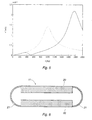
- the diagram in Figure 5 shows vibration velocity as a function of frequency.
- the two curves in the diagram constitute the calculated result of the vibration velocity at the outer ends of the capacitor package at an applied driving force, sweeping by frequency.
- the dash-dotted curve represents the homogeneous capacitor package 10 which has a resonance at 1000 Hz.
- the unbroken curve represents the capacitor package 10a, 10b, divided by a weak spring element 11. It has two resonances, one at 350 Hz and one at 1750 Hz.
- the result also shows that in the latter case an anti-resonance occurs at 500 Hz, which is a result of the mechanical system, divided by spring elements, receiving more degrees of freedom.
- the oscillation resistance is infinitely great at the end surfaces of the capacitor package and hence the movement is, in principle, zero whereas the spring elements take up the whole movement.
- Figure 6 shows an embodiment of a spring element 11. It consists of an evacuated plane-parallel, tight container of metal, the upper side and underside of which in Figure 6 are made of thick, stiff plates 20, and the edges 21 of which on all sides are made of thin sheet strips of semicircular cross section fixed to each plate 20.
- the completed spring element has a shape like a parallelepiped formed with rounded edges and with the same plane dimensions as the capacitor packages.
- the mechanical construction of a capacitor can be chosen in an optimum way, by the introduction of one or more weak springs, such that the natural frequencies are located far away from the frequencies of the critical force components.
- An optimum mechanical embodiment is then obtained when the introduced spring elements are dimensioned such that anti-resonances occur at the same frequencies as the dominating driving forces.
- Passive spring elements are such devices where the resilient properties are determined by the shape and material of the spring and cannot be changed by external influence.
- An active spring element may be built up in the same way as a passive element but of a material whose properties, such as volume or shape, may be changed by external energy supply, for example magnetostrictive or piezoelectric materials.
- the spring element may be constructed as a hollow parallelepiped, the walls of which are tight (impermeable for gas), of some material corrodibly resistant to the insulating fluid, such as, for example, metal or plastic.
- the spring element instead of consisting of a hollow body, may also consist of a solid body the material of which exhibits elastic properties and is resistant to the surrounding medium.
- the spring element comprises the desired vibration-absorbing properties and may either itself constitute the resilient device, or a device with the desired properties may be enclosed in a container which constitutes the spring element.
Landscapes
- Engineering & Computer Science (AREA)
- Power Engineering (AREA)
- Manufacturing & Machinery (AREA)
- Microelectronics & Electronic Packaging (AREA)
- Fixed Capacitors And Capacitor Manufacturing Machines (AREA)
- Soundproofing, Sound Blocking, And Sound Damping (AREA)
Claims (7)
- Condensateur électrique comprenant au moins deux éléments (2) de condensateur qui sont constitués par des électrodes (5) séparées par un ou plusieurs diélectriques (6), ces éléments de condensateur étant disposés en une rangée pour former un module (10) de condensateur, caractérisé en ce qu'au moins un élément (11) à ressort est disposé entre une paire d'éléments de condensateur adjacents dans la rangée, ou est fixé à l'extérieur de l'élément de condensateur à une extrémité de la rangée, et en ce que la raideur de l'élément à ressort est adaptée ou est adaptable de façon que les vibrations externes du condensateur, qui sont occasionnées par les forces d'entraínement oscillatoires dans les éléments de condensateur, soient réduites, ce qui conduit à une émission sonore réduite à partir du condensateur.
- Condensateur électrique selon la revendication 1, caractérisé en ce que chaque élément (2) de condensateur comprend un rouleau bobiné à partir de feuilles (5) de métal et de pellicules (6) diélectriques placées entre les feuilles de métal.
- Condensateur électrique selon la revendication 1 ou 2, caractérisé en ce que les éléments (2) de condensateur et l'élément ou les éléments à ressort sont entourés par un fluide électriquement isolant qui est contenu dans une cuve (4) de condensateur.
- Condensateur électrique selon la revendication 3, caractérisé en ce que la cuve de condensateur comprend des traversées (1) et une isolation (3) de protection.
- Condensateur électrique selon l'une quelconque des revendications précédentes, caractérisé en ce que le ou les eléments (11) à ressort comprennent une enceinte étanche en métal ou en matière plastique, dans laquelle on a fait le vide.
- Condensateur électrique selon l'une quelconque des revendications précédentes, caractérisé en ce que l'élément (11) à ressort comprend un dispositif à ressort passif dont les caractéristiques sont déterminées par le matériau et la forme.
- Condensateur électrique selon l'une quelconque des revendications 1 à 6, caractérisé en ce que l'élément (11) à ressort comprend un dispositif à ressort actif pouvant être actionné de façon active par une application d'énergie externe.
Applications Claiming Priority (2)
| Application Number | Priority Date | Filing Date | Title |
|---|---|---|---|
| SE9402178A SE503305C2 (sv) | 1994-06-21 | 1994-06-21 | Kondensator |
| SE9402178 | 1994-06-21 |
Publications (2)
| Publication Number | Publication Date |
|---|---|
| EP0701263A1 EP0701263A1 (fr) | 1996-03-13 |
| EP0701263B1 true EP0701263B1 (fr) | 1998-08-26 |
Family
ID=20394464
Family Applications (1)
| Application Number | Title | Priority Date | Filing Date |
|---|---|---|---|
| EP95109284A Expired - Lifetime EP0701263B1 (fr) | 1994-06-21 | 1995-06-15 | Condensateur électrique |
Country Status (6)
| Country | Link |
|---|---|
| US (1) | US5563763A (fr) |
| EP (1) | EP0701263B1 (fr) |
| JP (1) | JP3851670B2 (fr) |
| DE (1) | DE69504260T2 (fr) |
| FI (1) | FI114754B (fr) |
| SE (1) | SE503305C2 (fr) |
Cited By (1)
| Publication number | Priority date | Publication date | Assignee | Title |
|---|---|---|---|---|
| US10658119B1 (en) | 2017-04-26 | 2020-05-19 | Abb Schweiz Ag | Multielectrode power capacitor with reduce noise vibration |
Families Citing this family (6)
| Publication number | Priority date | Publication date | Assignee | Title |
|---|---|---|---|---|
| JP4217925B2 (ja) * | 1997-10-24 | 2009-02-04 | ソニー株式会社 | 平面型レンズの製造方法 |
| SE0003565D0 (sv) * | 2000-10-04 | 2000-10-04 | Abb Ab | Kondensatorelement för en kraftkondensator samt kraftkondensator innefattande ett dylikt kondensatorelement |
| US6644617B2 (en) * | 2000-12-06 | 2003-11-11 | Nelson Douglas Pitlor | Remotely attachable and separable coupling |
| DE102013211699A1 (de) * | 2013-06-20 | 2014-12-24 | Siemens Aktiengesellschaft | Kondensatoreinrichtung |
| CN110571050B (zh) * | 2019-10-15 | 2024-10-29 | 西安交通大学 | 电容器和质量谐振板的质量确定方法 |
| CN110581020B (zh) * | 2019-10-15 | 2024-10-29 | 西安交通大学 | 电容器和刚度谐振元件的刚度确定方法 |
Family Cites Families (3)
| Publication number | Priority date | Publication date | Assignee | Title |
|---|---|---|---|---|
| US3484664A (en) * | 1968-11-21 | 1969-12-16 | Hercules Inc | Electrical capacitors |
| DE2937983C2 (de) * | 1979-09-20 | 1984-09-20 | Felten & Guilleaume Energietechnik GmbH, 5000 Köln | Freiluftkondensator |
| JPS58189915A (ja) * | 1982-04-30 | 1983-11-05 | ブラザー工業株式会社 | 可変容量型キ−スイツチ及びその製造方法 |
-
1994
- 1994-06-21 SE SE9402178A patent/SE503305C2/sv not_active IP Right Cessation
-
1995
- 1995-06-13 US US08/490,008 patent/US5563763A/en not_active Expired - Lifetime
- 1995-06-15 EP EP95109284A patent/EP0701263B1/fr not_active Expired - Lifetime
- 1995-06-15 DE DE69504260T patent/DE69504260T2/de not_active Expired - Lifetime
- 1995-06-20 FI FI953037A patent/FI114754B/fi not_active IP Right Cessation
- 1995-06-21 JP JP15493095A patent/JP3851670B2/ja not_active Expired - Fee Related
Cited By (1)
| Publication number | Priority date | Publication date | Assignee | Title |
|---|---|---|---|---|
| US10658119B1 (en) | 2017-04-26 | 2020-05-19 | Abb Schweiz Ag | Multielectrode power capacitor with reduce noise vibration |
Also Published As
| Publication number | Publication date |
|---|---|
| FI953037A0 (fi) | 1995-06-20 |
| JPH0855751A (ja) | 1996-02-27 |
| DE69504260T2 (de) | 1999-05-06 |
| FI114754B (fi) | 2004-12-15 |
| SE503305C2 (sv) | 1996-05-13 |
| FI953037L (fi) | 1995-12-22 |
| EP0701263A1 (fr) | 1996-03-13 |
| DE69504260D1 (de) | 1998-10-01 |
| US5563763A (en) | 1996-10-08 |
| SE9402178D0 (sv) | 1994-06-21 |
| SE9402178L (sv) | 1995-12-22 |
| JP3851670B2 (ja) | 2006-11-29 |
Similar Documents
| Publication | Publication Date | Title |
|---|---|---|
| Lefeuvre et al. | Semi-passive piezoelectric structural damping by synchronized switching on voltage sources | |
| US4104920A (en) | Piezoelectric damping mechanism | |
| Silva et al. | Design of piezoelectric transducers using topology optimization | |
| Roundy | On the effectiveness of vibration-based energy harvesting | |
| Law et al. | Characterization of mechanical vibration damping by piezoelectric materials | |
| CN110566619B (zh) | 一种粒子阻尼声子晶体结构及其等效理论模型构建方法 | |
| Kim et al. | New shunting parameter tuning method for piezoelectric damping based on measured electrical impedance | |
| Petit et al. | A broadband semi passive piezoelectric technique for structural damping | |
| EP0701263B1 (fr) | Condensateur électrique | |
| Iula et al. | A model for the theoretical characterization of thin piezoceramic rings | |
| Hollkamp et al. | An experimental comparison of piezoelectric and constrained layer damping | |
| Li et al. | Finite element analysis on piezoelectric ring transformer | |
| Chebanenko et al. | Numerical optimization of the piezoelectric generators | |
| CN114483869A (zh) | 一种基于压电非线性能量阱的柔性板减振装置和方法 | |
| Yang et al. | A vibrating piezoelectric ceramic shell as a rotation sensor | |
| US5541467A (en) | Vibrating unit | |
| Xiong et al. | On the use of piezoelectric nonlinear energy sink for vibration isolation and energy harvesting | |
| Park et al. | Enhanced piezoelectric shunt design | |
| Margielewicz et al. | Energy harvesting efficiency of a quasi-zero stiffness system | |
| Shan et al. | Design and experiment of multiple piezoelectric bimorphs for scavenging vibration energy | |
| Dai et al. | Two kinds equal frequency circuits to achieve locally resonant band gap of a circular plate attached alternately by Piezoelectric Unimorphs | |
| Moura et al. | Vibration and wave propagation control in a smart metamaterial beam with periodic arrays of shunted piezoelectric patches | |
| Pak et al. | An approach to designing a dual frequency piezoelectric ultrasonic transducer | |
| Mir et al. | Performance of a Multifunctional Spiral Shaped Acoustic Metamaterial With Synchronized Low-Frequency Noise Filtering and Energy Harvesting Capability | |
| Gardonio et al. | Smart panel with multiple decentralised units for the control of sound transmission. Part II: Design of the decentralised control units |
Legal Events
| Date | Code | Title | Description |
|---|---|---|---|
| PUAI | Public reference made under article 153(3) epc to a published international application that has entered the european phase |
Free format text: ORIGINAL CODE: 0009012 |
|
| AK | Designated contracting states |
Kind code of ref document: A1 Designated state(s): CH DE FR GB IT LI |
|
| 16A | New documents despatched to applicant after publication of the search report | ||
| 17P | Request for examination filed |
Effective date: 19960508 |
|
| GRAG | Despatch of communication of intention to grant |
Free format text: ORIGINAL CODE: EPIDOS AGRA |
|
| 17Q | First examination report despatched |
Effective date: 19970925 |
|
| GRAG | Despatch of communication of intention to grant |
Free format text: ORIGINAL CODE: EPIDOS AGRA |
|
| GRAH | Despatch of communication of intention to grant a patent |
Free format text: ORIGINAL CODE: EPIDOS IGRA |
|
| GRAH | Despatch of communication of intention to grant a patent |
Free format text: ORIGINAL CODE: EPIDOS IGRA |
|
| GRAA | (expected) grant |
Free format text: ORIGINAL CODE: 0009210 |
|
| AK | Designated contracting states |
Kind code of ref document: B1 Designated state(s): CH DE FR GB IT LI |
|
| REG | Reference to a national code |
Ref country code: CH Ref legal event code: EP |
|
| REF | Corresponds to: |
Ref document number: 69504260 Country of ref document: DE Date of ref document: 19981001 |
|
| ET | Fr: translation filed | ||
| REG | Reference to a national code |
Ref country code: CH Ref legal event code: NV Representative=s name: PATENTANWAELTE SCHAAD, BALASS, MENZL & PARTNER AG |
|
| PLBE | No opposition filed within time limit |
Free format text: ORIGINAL CODE: 0009261 |
|
| STAA | Information on the status of an ep patent application or granted ep patent |
Free format text: STATUS: NO OPPOSITION FILED WITHIN TIME LIMIT |
|
| 26N | No opposition filed | ||
| REG | Reference to a national code |
Ref country code: GB Ref legal event code: IF02 |
|
| PGFP | Annual fee paid to national office [announced via postgrant information from national office to epo] |
Ref country code: CH Payment date: 20080611 Year of fee payment: 14 |
|
| PGFP | Annual fee paid to national office [announced via postgrant information from national office to epo] |
Ref country code: GB Payment date: 20080618 Year of fee payment: 14 |
|
| REG | Reference to a national code |
Ref country code: CH Ref legal event code: PL |
|
| GBPC | Gb: european patent ceased through non-payment of renewal fee |
Effective date: 20090615 |
|
| PG25 | Lapsed in a contracting state [announced via postgrant information from national office to epo] |
Ref country code: LI Free format text: LAPSE BECAUSE OF NON-PAYMENT OF DUE FEES Effective date: 20090630 Ref country code: CH Free format text: LAPSE BECAUSE OF NON-PAYMENT OF DUE FEES Effective date: 20090630 |
|
| PG25 | Lapsed in a contracting state [announced via postgrant information from national office to epo] |
Ref country code: GB Free format text: LAPSE BECAUSE OF NON-PAYMENT OF DUE FEES Effective date: 20090615 |
|
| PGFP | Annual fee paid to national office [announced via postgrant information from national office to epo] |
Ref country code: DE Payment date: 20130612 Year of fee payment: 19 |
|
| PGFP | Annual fee paid to national office [announced via postgrant information from national office to epo] |
Ref country code: IT Payment date: 20130620 Year of fee payment: 19 Ref country code: FR Payment date: 20130624 Year of fee payment: 19 |
|
| REG | Reference to a national code |
Ref country code: DE Ref legal event code: R082 Ref document number: 69504260 Country of ref document: DE Representative=s name: WEICKMANN & WEICKMANN, DE Ref country code: DE Ref legal event code: R082 Ref document number: 69504260 Country of ref document: DE Representative=s name: HANSMANN & VOGESER, DE |
|
| REG | Reference to a national code |
Ref country code: DE Ref legal event code: R119 Ref document number: 69504260 Country of ref document: DE |
|
| REG | Reference to a national code |
Ref country code: FR Ref legal event code: ST Effective date: 20150227 |
|
| REG | Reference to a national code |
Ref country code: DE Ref legal event code: R119 Ref document number: 69504260 Country of ref document: DE Effective date: 20150101 |
|
| PG25 | Lapsed in a contracting state [announced via postgrant information from national office to epo] |
Ref country code: IT Free format text: LAPSE BECAUSE OF NON-PAYMENT OF DUE FEES Effective date: 20140615 Ref country code: DE Free format text: LAPSE BECAUSE OF NON-PAYMENT OF DUE FEES Effective date: 20150101 |
|
| PG25 | Lapsed in a contracting state [announced via postgrant information from national office to epo] |
Ref country code: FR Free format text: LAPSE BECAUSE OF NON-PAYMENT OF DUE FEES Effective date: 20140630 |