EP0701181A2 - Toner bottle and manufacturing method therefor - Google Patents
Toner bottle and manufacturing method therefor Download PDFInfo
- Publication number
- EP0701181A2 EP0701181A2 EP95306333A EP95306333A EP0701181A2 EP 0701181 A2 EP0701181 A2 EP 0701181A2 EP 95306333 A EP95306333 A EP 95306333A EP 95306333 A EP95306333 A EP 95306333A EP 0701181 A2 EP0701181 A2 EP 0701181A2
- Authority
- EP
- European Patent Office
- Prior art keywords
- bottle
- toner
- less
- recesses
- projections
- Prior art date
- Legal status (The legal status is an assumption and is not a legal conclusion. Google has not performed a legal analysis and makes no representation as to the accuracy of the status listed.)
- Granted
Links
Images


Classifications
-
- G—PHYSICS
- G03—PHOTOGRAPHY; CINEMATOGRAPHY; ANALOGOUS TECHNIQUES USING WAVES OTHER THAN OPTICAL WAVES; ELECTROGRAPHY; HOLOGRAPHY
- G03G—ELECTROGRAPHY; ELECTROPHOTOGRAPHY; MAGNETOGRAPHY
- G03G15/00—Apparatus for electrographic processes using a charge pattern
- G03G15/06—Apparatus for electrographic processes using a charge pattern for developing
- G03G15/10—Apparatus for electrographic processes using a charge pattern for developing using a liquid developer
-
- B—PERFORMING OPERATIONS; TRANSPORTING
- B65—CONVEYING; PACKING; STORING; HANDLING THIN OR FILAMENTARY MATERIAL
- B65D—CONTAINERS FOR STORAGE OR TRANSPORT OF ARTICLES OR MATERIALS, e.g. BAGS, BARRELS, BOTTLES, BOXES, CANS, CARTONS, CRATES, DRUMS, JARS, TANKS, HOPPERS, FORWARDING CONTAINERS; ACCESSORIES, CLOSURES, OR FITTINGS THEREFOR; PACKAGING ELEMENTS; PACKAGES
- B65D1/00—Containers having bodies formed in one piece, e.g. by casting metallic material, by moulding plastics, by blowing vitreous material, by throwing ceramic material, by moulding pulped fibrous material, by deep-drawing operations performed on sheet material
- B65D1/02—Bottles or similar containers with necks or like restricted apertures, designed for pouring contents
- B65D1/0223—Bottles or similar containers with necks or like restricted apertures, designed for pouring contents characterised by shape
-
- G—PHYSICS
- G03—PHOTOGRAPHY; CINEMATOGRAPHY; ANALOGOUS TECHNIQUES USING WAVES OTHER THAN OPTICAL WAVES; ELECTROGRAPHY; HOLOGRAPHY
- G03G—ELECTROGRAPHY; ELECTROPHOTOGRAPHY; MAGNETOGRAPHY
- G03G15/00—Apparatus for electrographic processes using a charge pattern
- G03G15/06—Apparatus for electrographic processes using a charge pattern for developing
- G03G15/08—Apparatus for electrographic processes using a charge pattern for developing using a solid developer, e.g. powder developer
- G03G15/0822—Arrangements for preparing, mixing, supplying or dispensing developer
- G03G15/0865—Arrangements for supplying new developer
- G03G15/0867—Arrangements for supplying new developer cylindrical developer cartridges, e.g. toner bottles for the developer replenishing opening
- G03G15/087—Developer cartridges having a longitudinal rotational axis, around which at least one part is rotated when mounting or using the cartridge
-
- G—PHYSICS
- G03—PHOTOGRAPHY; CINEMATOGRAPHY; ANALOGOUS TECHNIQUES USING WAVES OTHER THAN OPTICAL WAVES; ELECTROGRAPHY; HOLOGRAPHY
- G03G—ELECTROGRAPHY; ELECTROPHOTOGRAPHY; MAGNETOGRAPHY
- G03G15/00—Apparatus for electrographic processes using a charge pattern
- G03G15/06—Apparatus for electrographic processes using a charge pattern for developing
- G03G15/08—Apparatus for electrographic processes using a charge pattern for developing using a solid developer, e.g. powder developer
- G03G15/0822—Arrangements for preparing, mixing, supplying or dispensing developer
- G03G15/0865—Arrangements for supplying new developer
- G03G15/0875—Arrangements for supplying new developer cartridges having a box like shape
-
- G—PHYSICS
- G03—PHOTOGRAPHY; CINEMATOGRAPHY; ANALOGOUS TECHNIQUES USING WAVES OTHER THAN OPTICAL WAVES; ELECTROGRAPHY; HOLOGRAPHY
- G03G—ELECTROGRAPHY; ELECTROPHOTOGRAPHY; MAGNETOGRAPHY
- G03G15/00—Apparatus for electrographic processes using a charge pattern
- G03G15/06—Apparatus for electrographic processes using a charge pattern for developing
- G03G15/08—Apparatus for electrographic processes using a charge pattern for developing using a solid developer, e.g. powder developer
- G03G15/0822—Arrangements for preparing, mixing, supplying or dispensing developer
- G03G15/0877—Arrangements for metering and dispensing developer from a developer cartridge into the development unit
- G03G15/0881—Sealing of developer cartridges
- G03G15/0886—Sealing of developer cartridges by mechanical means, e.g. shutter, plug
-
- B—PERFORMING OPERATIONS; TRANSPORTING
- B65—CONVEYING; PACKING; STORING; HANDLING THIN OR FILAMENTARY MATERIAL
- B65D—CONTAINERS FOR STORAGE OR TRANSPORT OF ARTICLES OR MATERIALS, e.g. BAGS, BARRELS, BOTTLES, BOXES, CANS, CARTONS, CRATES, DRUMS, JARS, TANKS, HOPPERS, FORWARDING CONTAINERS; ACCESSORIES, CLOSURES, OR FITTINGS THEREFOR; PACKAGING ELEMENTS; PACKAGES
- B65D2501/00—Containers having bodies formed in one piece
- B65D2501/0009—Bottles or similar containers with necks or like restricted apertures designed for pouring contents
- B65D2501/0018—Ribs
-
- B—PERFORMING OPERATIONS; TRANSPORTING
- B65—CONVEYING; PACKING; STORING; HANDLING THIN OR FILAMENTARY MATERIAL
- B65D—CONTAINERS FOR STORAGE OR TRANSPORT OF ARTICLES OR MATERIALS, e.g. BAGS, BARRELS, BOTTLES, BOXES, CANS, CARTONS, CRATES, DRUMS, JARS, TANKS, HOPPERS, FORWARDING CONTAINERS; ACCESSORIES, CLOSURES, OR FITTINGS THEREFOR; PACKAGING ELEMENTS; PACKAGES
- B65D2501/00—Containers having bodies formed in one piece
- B65D2501/0009—Bottles or similar containers with necks or like restricted apertures designed for pouring contents
- B65D2501/0081—Bottles of non-circular cross-section
-
- G—PHYSICS
- G03—PHOTOGRAPHY; CINEMATOGRAPHY; ANALOGOUS TECHNIQUES USING WAVES OTHER THAN OPTICAL WAVES; ELECTROGRAPHY; HOLOGRAPHY
- G03G—ELECTROGRAPHY; ELECTROPHOTOGRAPHY; MAGNETOGRAPHY
- G03G2215/00—Apparatus for electrophotographic processes
- G03G2215/06—Developing structures, details
- G03G2215/066—Toner cartridge or other attachable and detachable container for supplying developer material to replace the used material
- G03G2215/0663—Toner cartridge or other attachable and detachable container for supplying developer material to replace the used material having a longitudinal rotational axis, around which at least one part is rotated when mounting or using the cartridge
- G03G2215/0673—Generally vertically mounting of said toner cartridge parallel to its longitudinal rotational axis
-
- G—PHYSICS
- G03—PHOTOGRAPHY; CINEMATOGRAPHY; ANALOGOUS TECHNIQUES USING WAVES OTHER THAN OPTICAL WAVES; ELECTROGRAPHY; HOLOGRAPHY
- G03G—ELECTROGRAPHY; ELECTROPHOTOGRAPHY; MAGNETOGRAPHY
- G03G2215/00—Apparatus for electrophotographic processes
- G03G2215/06—Developing structures, details
- G03G2215/066—Toner cartridge or other attachable and detachable container for supplying developer material to replace the used material
- G03G2215/0663—Toner cartridge or other attachable and detachable container for supplying developer material to replace the used material having a longitudinal rotational axis, around which at least one part is rotated when mounting or using the cartridge
- G03G2215/0678—Bottle shaped container having a bottle neck for toner discharge
-
- G—PHYSICS
- G03—PHOTOGRAPHY; CINEMATOGRAPHY; ANALOGOUS TECHNIQUES USING WAVES OTHER THAN OPTICAL WAVES; ELECTROGRAPHY; HOLOGRAPHY
- G03G—ELECTROGRAPHY; ELECTROPHOTOGRAPHY; MAGNETOGRAPHY
- G03G2215/00—Apparatus for electrophotographic processes
- G03G2215/06—Developing structures, details
- G03G2215/066—Toner cartridge or other attachable and detachable container for supplying developer material to replace the used material
- G03G2215/0692—Toner cartridge or other attachable and detachable container for supplying developer material to replace the used material using a slidable sealing member, e.g. shutter
Definitions
- the present invention relates to a toner bottle and a toner bottle manufacturing method for supplying powdery developer to an image forming apparatus such as a dry type electrophotographic copying machine or printer.
- a photosensitive drum uniformly charged is selectively exposed to light to form a latent image, which is visualized by toner, and the toner image is transferred onto a recording material such as paper.
- the toner has to be replenished.
- a toner bottle having an opening at a longitudinal end thereof is used, particularly, a toner bottle having a relatively large capacity not less than 1000 cm3 is preferably used.
- the toner bottle contains a predetermined amount of toner, and is sealed by capping, and is sent to a user.
- the cap When the cap is mounted to the bottle, the bottle has a male screw, and the cap has a female.
- the toner is generally powdery containing particles having a volume average particle size of 20 ⁇ m or smaller.
- a gasket of rubber or elastomer is frequently used.
- the user supplies the toner from the toner bottle in the copying machine, printer or another image forming apparatus main assembly.
- the cap is provided with a rotary shutter, slide shutter or another opening mechanism.
- the toner bottle is mounted to the main assembly of the image forming apparatus with the cap downward, and them, the opening mechanism is released to permit the toner fall into the main assembly.
- the cap of the toner bottle and the toner receptor opening of the image forming apparatus are coupled with sealed state to prevent leakage or scattering of the toner during the toner replenishment.
- the toner has a tendency of bridging, particularly, the toner tends to plug a throat adjacent the shutter mechanism or adjacent inclined portions of the bottle.
- the user may strongly presses the toner bottle to forcedly discharge the toner with the result of a large amount of air and a large amount of toner are abruptly fed with the possible result of blowing of the toner between the cap and the toner receptor opening. Therefore, the toner bottle is required to have such a rigidity that it does not deform even if pressed by the operator's hands.
- the toner bottle has been produced by direct blowing method, usually. Because of the limitation from the manufacturing method and the requirement for the rigidity of the toner bottle, the thickness of the bottle is relatively large, and the minimum thickness is usually 1.0 - 3.0 mm approx.
- the product is taken out of the metal mold, and the parison at the opening and the bottom is removed. Then, usually the finishing process has been carried out to improve the surface property of the surface to which the gasket is contacted to assure the sealing property.
- the cap When the cap is provided with a rotary shutter, the cap and the bottle have to be rotated to close or open the shutter when the toner bottle is mounted on the image forming apparatus.
- the cap may be provided with a lever or handle.
- the angular position of the cap has to be within a predetermined range to permit contact packaging of the toner bottle.
- the dimensional accuracy is required in the screw at the end of the bottle and the longitudinal dimension thereof. In this case, the finishing process for the end surface of the opening is particularly important.
- a stopper mechanism is provided to prevent rotation, thus preventing loosening of the cap.
- stopper projections are provided adjacent the opening of the toner bottle and adjacent the toner bottle side end of the cap thus the rotation is prevented by the abutment therebetween.
- the increase of the plastic material waste is one of social problems, so that the demand for the reduction of the amount of the used material (source reduction) becomes strong.
- source reduction the toner blowing or break during transportation may occur, if the thickness is simply reduced.
- the parison removal or the end finishing is required with the result of increase of the manufacturing cost. Additionally, the positional accuracies such as the distance from the end of the opening to the screw and the surface property of the end surface of the opening, tend to vary, with the result of toner leakage or improper angular position of the cap.
- the thickness is smaller at the corner or the like of the projection, which may lead to pin hole. This is particularly remarkable when polypropylene resin is used, because it does not exhibit self curing property.
- the inside surface corresponding to the projection or screw is concave ( Figure 11) with the result of easy stagnation of the toner upon the toner replenishing operation.
- the recess may initiate the toner bridging with the result of tendency of plugging with the toner. Additionally, the stagnation of the toner in the recess may increase the remaining amount of the toner, which may scatter.
- the minimum thickness is 1.5 mm, but the transparency of the material is still low even if the use is made with random copolymer resin material of polypropylene and polyethylene exhibiting high anti-impact property even at the low temperature.
- the low temperature anti-shock strength increases with increase of the ethylene content, but the rigidity and the transparency become poor.
- the ethylene content is at least 3.0 % to provide sufficient low temperature falling test. With this content, the copolymer resin exhibits low rigidity, and therefore, the thickness cannot be decreased, and therefore, the transparency improvement is difficult.
- a toner bottle for containing powder toner comprising: a toner supply opening at one longitudinal end; lateral recesses or projections extending in a direction crossing with a longitudinal direction of the bottle; and a plurality of longitudinal recesses or projections extending substantially in the longitudinal direction in both sides of the lateral recesses or projections.
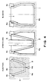
- Figure 1 is a perspective view of a toner bottle according to an embodiment of the present invention.
- Figure 2 is a detailed sectional view of a screw portion of a toner bottle according to an embodiment of the present invention.
- Figure 3 is a sectional view showing details of a rib on the surface of the toner bottle.
- Figure 4 is a schematic view illustrating manufacturing steps of toner bottle according to an embodiment of the present invention.
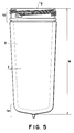
- Figure 5 is front view of preforming produced by injection step in a toner bottle manufacturing method according to an embodiment of the present invention.
- Figure 6 is an exploded perspective view of a cap according to an embodiment of the present invention.
- Figure 7 is a detailed sectional view of a toner bottle on which a cap is mounted.
- Figure 8 is a top plan view of a toner bottle to which a cap is mounted.
- Figure 9 is a perspective view of a toner bottle which is going to be mounted on a toner receptor of an image forming apparatus.
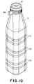
- Figure 10 is a perspective view of a toner bottle according to a comparison example.
- Figure 11 is a detailed sectional view of a screw of a toner bottle according to a Comparison Example.
- Figure 12 is a schematic view illustrating a manufacturing step of a toner bottle according to a comparison example.
- Figure 1 is a perspective view of a toner bottle according to an embodiment of the present invention.
- Figure 2 is a detailed sectional view of a threaded opening of the toner bottle.
- reference numeral 1 designates a bottle portion of the toner bottle
- 1a and 1b are groove or rib extending along the length of the bottle
- 1c is a groove or rib extending in a direction crossing with (perpendicular to, in this embodiment) the length of the bottle
- 1g is an opening of the toner bottle
- 1e is a bottom of the bottle at the opposite side of the opening 1d
- 1f is a substantially middle portion of the bottle in the longitudinal direction
- 2 is a cap
- 2a is a grip or handle in the form of a lever of the cap.
- a groove (recess) la extends toward the central portion 1f of the bottle adjacent to the opening 1d, and a plurality of them are formed at regular intervals.
- Grooves (recesses) 1b extend toward the central portion of the bottle 1f adjacent to the bottom 1e, and are formed at regular intervals.
- the grooves (recesses) 1c are circumferentially formed substantially at the central portion 1b of the bottle.
- the grooves are uniformly distributed all over the surface of the bottle.
- the grooves 1a and 1b are close to the opening 1d and bottom la having high rigidity.
- the circular grooves 1c substantially perpendicularly extended to the longitudinal direction, are disposed adjacent the central portion 1f of the bottle to efficiently increase the rigidity.
- the size and the number of the ribs are preferably such that they occupy not less than 10 % and not more than 50 % of the entire surface area of the bottle. More preferably, it is not less than 20 % and not more than 40 %, further preferably not less than 25 % and not more than 35 %. If it is less than 10 %, the rigidity increasing effect and the toner loosening effect are not sufficient.
- the surface area of the hole bottle is approx. 1841 cm, and the area of the grooves is approx. 501 cm, and therefore, they occupy approx. 27 %.
- the balance between the grooves 1a and 1b extending in the longitudinal direction and perpendicular circular grooves 1c, is preferably such that the former is not less than 50 % and not more than 90 % of the entire area of the grooves, more particularly, it is not less than 60 % and not more than 80 %, further preferably not less than 65 % and not more than 75 %. If the longitudinal grooves exceed 90 %, that is, the perpendicular grooves are less than 10 %, the toner loosening effect is hardly provided. In addition, the rigidity adjacent the central portion 1f is insufficient. This is close to grooves only in one direction, and the resistance against the bottle collapse is hardly provided.
- the percentage of the longitudinal grooves is less than 50 %, the strength of the opening and the bottom are not enjoyed by the central portion of the bottle with the result of easily deformation in the bottle yielding direction.
- the above-described percentages are preferable.
- the area of the ribs 1a and 1b extending in the longitudinal direction is approx. 336 cm, and the area of the circular ribs 1c is approx. 165 cm (approx. 67 %).
- Figure 3 is a detailed sectional view of grooves or ribs 1a, 1b and 1c.
- the width of the rib is preferably not less than 3 mm and not more than 20 mm, further preferably not less than 5 mm and not more than 15 mm, most preferably not less than 7 mm and not more than 12 mm.
- the depth of the rib is preferably not less than 0.5 % and not more than 20 % of the distance between inner wall of the container, more preferably not less than 2 % and not more than 10 %. If the width of the rib exceeds 20 mm, the rigidity is not transmitted from the bottom end to the bottle central portion, and if it is less than 3 mm, the transfer to the metal mold during the molding operation is difficult. If the depth of the groove exceeds 20 % of the distance between the inner wall, the toner discharge is obstructed.
- the distance between inner wall (inner diameter) is approx. 107 mm and the depth of the groove is approx. 3.3 %.
- the thickness of the toner bottle 1 of this embodiment is determined as follows. First, adjacent the opening 1d not extended by the injection step, it is 2.0 mm, and it is 2.5 mm adjacent the bottom which is not expanded either. In the expanded portion having the grooves 1a, 1b and 1c, it is 0.8 - 1.1 mm in the average over the circumference at a longitudinal portion, and the minimum is not less than 0.6 mm. The weight of the bottle is 196 g.
- the thickness of the bottle As to the relationship between the thickness of the bottle and the rigidity, it is preferable to control the average thickness over the circumference. Even if there is a thin portion, the rigidity may be sufficient if the portion adjacent thereto is thick. There is a high interrelation between the average thickness and the rigidity. The reason is as follows. Injection/stretch/blow method is used to mold it, substantially uniform thickness is provided in the circumferential direction in the preform of the injection molding. The bottle provided by blowing it has only local thickness variation, if any. Therefore, no wide thin portion does not result. The thickness of the bottle on the average is not less than 0.6 mm and not more than 3.0 mm, and the minimum thickness is not less than 0.4 mm and not more than 2.5 mm.
- the average thickness is not less than 0.7 mm and not more than 2.0 mm, and the minimum thickness is not less than 0.5 mm and not more than 1.5 mm. Most preferably, the average thickness is not less than 0.8 mm and not more than 1.2 mm, and the minimum thickness is not less than 0.6 mm and not more than 1.0 mm.
- This embodiment is particularly usable when the inner volume of toner is not less than 1000 cm3 and not more than 6000 cm3. Even if the bottle having such a small volume as less than 1000 cm3, does not result in the blowing of the toner even if the bottle is strongly pressed during the supplying operation, because the amount of the air pushed out is not large. Additionally, the rigidity is sufficient in such a small bottle. If the inner volume exceeds 6000 cm3, the operativity is remarkably poor when it is reversely erected to mount to the image forming apparatus. Additionally, the formation using the injection-stretch blowing method. The volume of the bottle in this embodiment is 3630 cm3. The inner volume of the bottle is measured by filling the bottle with water, and the weight of the water is divided by the specific gravity.
- the inner diameter of the toner bottle is preferably not less than 40 mm and not more than 110 mm. If it is less than 40 mm, the discharge of the fine powdery toner will be difficult. If it exceeds 110 mm, the formation by the injection/stretch-blowing method will be difficult. In this embodiment, it is 74.5 mm.
- the barrel diameter of the toner bottle is preferably not less than 80 mm and not more than 160 mm. If it is less than 80 mm, the expansion during the blowing step in the radial direction is not sufficient with the result of insufficient anti-impact property with the above-described thickness. If it exceeds 160 mm, the formation by the blowing step becomes difficult. Additionally, the operativity of the bottle is poor, and therefore, it is not practical.
- the barrel diameter is 108.5 mm.
- the height of the toner bottle is preferably not less than 200 mm and not more than 450 mm. If it is less than 200 mm, the longitudinal expansion in the stretch step is not sufficient, and therefore, no sufficient anti-impact property is provided with the above-described thickness. If the height exceeds 450 mm, the formation by the injection/stretch-blowing method is difficult. Additionally, the operativity is remarkably poor when the bottle is mounted to the image forming apparatus, and therefore, it is not practical. In this embodiment, the height is 420 mm. As to the material of the toner bottle, random copolymer resin of the polypropylene and polyethylene is preferable from the standpoint of the rigidity, transparency, anti-impact property at low temperature and the cost.
- the ethylene content is not less than 1.0 % and not more than 3.0 %. More preferably, it is not less than 1.3 % and not more than 2.5 %. Most preferably, it is not less than 1.8 % and not more than 2.0 %. If it exceeds 3 %, the rigidity and the transparency are not sufficient even with the above-described groove structure and the thickness. On the other hand, if it is less than 1.0 %, the solidification speed is low with the result of the difficulty in the stretching and blowing step. Additionally, anti-impact property is insufficient so that the bottle is broken in the falling test.
- Figure 4 schematically shows the toner bottle manufacturing steps, including injection step, stretching step and blowing step.
- Figure 5 is a front view of a preform produced by the injection step.
- reference numeral 3 designates the preform
- 4 is a metal mold
- 4a is an injection mold
- 4b is a blowing mold
- 4c is a neck metal mold common to all steps
- 4d is a gate
- 5 is a stretching rod.
- the injection step resin material is injected into the metal mold through a gate 4b from an unshown dispenser in the known injection molding manner.
- the preform 3 is transferred to a blowing metal mold 4b, and the preform is expanded in the longitudinal direction by a stretching rod 5.
- compressed air is injected into the preform 3 to provide a bottle of a predetermined shape by the blowing mold 4b the blowing mold 4b is provided with projections extending in the circumferential direction, and a projection extended in the longitudinal direction at the opposite sides of the circumferential projections.
- the inner shape of the mold 4b is transferred onto the bottle, thus providing the bottle of Figure 1.
- the mold 4b is divided into two parts, and are removed in the direction perpendicular to the blowing direction.
- the preform 3 has a height h which is lower than the final height H of the bottle. By doing so, the stretch is increased by the expansion.
- the height ratio H/h is not less than 1.2 and not more than 2.5, preferably. If it is less than 1.2, a sufficient anti-impact property is not provided with the above-described thickness. With the increase of the ratio, the anti-impact property is increased, but in the case of the polypropylene resin, it is difficult to expand it to 2.5 times or larger.
- the thickness t of the preform is properly determined depending on the ratio H/h and the final thickness of the bottle. However, as contrasted to the usual bottle as in the bottle for drink, it has a relatively large thickness, and therefore, t is not less than 5 mm and not more than 10 mm, preferably. In this embodiment, the thickness of the preform is 6.5 mm.
- the portion 1d adjacent the opening and the portion 1e adjacent the bottom are neither expanded nor blown, and therefore, the thicknesses thereof is relatively large. Most of the part of the bottle other than those portions are expanded and blown into a small thickness.
- the weight of the toner bottle of this embodiment is 195 g.
- the conventional toner bottle having the same volume, as will be described hereinafter, with Figure 10, is 225 mm, and the reduction of the amount of the material decreases by as large as 13 %.
- Figure 6 is an exploded perspective view of a cap of the toner bottle used in this embodiment.
- reference 2a is a lever
- 2b is an outer frame of the cap
- 2c is a rotary shutter
- 2d is a fixed shutter
- 2e is a sector opening of a rotary shutter
- 2f is a sector opening of the fixed shutter
- 2g is a claw
- 2h is a sealing member
- 2i is a gasket.
- the fixed shutter 2d is fixed to the outer frame 2b of the cap by two claws 2g.
- the rotary shutter 2c is rotatable relative to the outer frame 2b of the cap. They are engaged into the outer frame 2b such that the sector openings 2e and 2f thereof are not aligned.
- the sealing member 2h is required to have the function of maintaining the hermetical sealing and functions to permit smooth closing and opening of the rotary shutter.
- the material thereof is foamed polyethylene material, foamed polypropylene material, foamed polystyrene, or various rubber sponge, preferably. Most preferably, it is of high density polyurethane foam material. In this embodiment, polyethylene foam having a thickness of 3.0 mm is used.
- the toner can be smoothly discharged. More particularly, the advantage of this embodiment is particularly remarkable when the ratio (W/a) of the area (a) cm of the discharging opening and the inside volume (W) of the bottle.
- the ratio (W/a) of the area (a) cm of the discharging opening and the inside volume (W) of the bottle In the case of such a small opening, if the bottle is transported or kept without use, that is, with the filled toner, the toner may be caked. If this occurs, it is difficult to smoothly discharge the toner.
- the area (a) of the sector openings 2e and 2f is 10.8 cm
- the inside volume of the bottom is 3630 cm3 as described hereinbefore, and therefore, ratio (W/a) is 336.
- Figure 7 is a detailed sectional view in which cap 2 is tightly closed on the bottle 1
- Figure 8 is a top plan view.
- a female screw is provided inside the outer frame 2b, and is threaded on the male screw of the toner bottle. It is preferable to interpose a gasket 2i between the opening end surface 1g of the bottle and the cap.
- gasket 2i there is various rubber materials or elastomers of proper hardness. In this embodiment, it is of olefin elastomer having a rubber hardness of 60 degrees and having a thickness of 2.0 mm and has been molded together with the fixed shutter. The rubber hardness is determined by a hardness tester of spring A type as stipulated in JIS-K-6130.
- the surface flatness has to be at a proper level.
- the surface roughness of the end surface is 0.25 mm and proper sealing properties have been exhibited in various tests.
- Cap 2 is provided with a grip or handle 2a. By manipulating it, the rotary shutter 2c is opened and closed.
- the cross-sectional shape of the bottle is substantially square with the corner rounded, as shown in Figure 8. Therefore, in order to package one bottle with the cap 2 securedly threaded, it is convenient that the handle 2a is aligned with a diagonal line of the square. More particularly, the angle of the handle lever 2a relative to the bottle 1 ( ⁇ is 45 ⁇ 7 degrees in this embodiment).
- the screws of the bottle and the cap are 3-lead screw with the lead of 12 mm, and therefore, the distance L from the bottle end surface to the starting end of the screw is formed within the tolerance of ⁇ 0.23 mm. In this embodiment of the toner bottle, the distance L can be within ⁇ 0.20 mm. Therefore, the lever 2a is within 45 ⁇ 6 degrees.
- the torque for threading the cap on the bottle is 200 kg.cm.
- a rotary shutter is built in the cap, and the shutter is opened or closed by rotating the cap with the lever 2a. It is therefore preferable that a rotation stepper mechanism is provided to prevent loosening of the cap.
- a stopper lh is provided adjacent the opening of the toner bottle
- a stopper 2j is provided adjacent the end of the toner bottle inside the outer frame 2b of the cap 2. The angular position of the mounting of the stopper projection is such that when the cap is completely threaded on the toner bottle, that is, when the end surface 1g of the toner bottle is closedly contacted to the gasket 2i, they are engaged.
- Figure 9 is a perspective view in which the toner bottle is going to be mounted to the toner receptor opening of the image forming apparatus, wherein reference numeral 5 designates the main assembly of the image forming apparatus, 5a is a toner supply opening, 5b is a lattice for preventing foreign matter or operator's fingers from entering the apparatus, and 5c is a projection.
- the toner bottle When the toner bottle is transported or simply kept, the toner may be caked due to escape of air by vibration or the like. In consideration of this fact, the toner bottle is vibrated for 10 minutes, and then it is subjected to the test.
- the toner bottle is shaked to cause the toner contain the air. This is done in order to loosen the agglomerated toner to decrease the apparent density of the toner, thus increasing the flowability.
- the ribs 1a, 1b and 1c projected from the inside surface of the toner bottle are effective to mix the air with the toner particles, thus promoting the loosening or uncaking. From the standpoint of the toner loosing, ribs substantially perpendicular to the longitudinal direction of the bottle are more contributable than the ribs 1a and 1b extending longitudinally.
- the toner bottle is turned around to orient the cap side downward, and it is mounted on the toner supply opening of the image forming apparatus 5.
- the recess 2k of the rotary shutter is engaged with a projection 5c of the image forming apparatus.
- the operator rotates the cap by the handle.
- the rotary shutter 2c is fixed on the image forming apparatus, and the fixed shutter 2d is fixed on the outer frame 2b of the cap by the flow 2g.
- the above-described rotation rotates it by a predetermined angle.
- the sector opening 2e of the rotary shutter and the sector opening 2e of the fixed shutter are aligned to permit the toner in the toner bottle fall into the image forming apparatus.
- the thickness of the toner bottle is relatively small, and therefore, the motion of the toner particles in the toner bottle during the toner supply can be sufficiently observed, so that the completion of the toner supply can be observed.
- the toner contains sufficient air to exhibit high flowability, and therefore, all of the toner in the bottle could be discharged in approx. 20 sec.
- the inside surface adjacent the opening of the toner bottle is smooth despite the provision of the projection and the male screw on the outer side.
- the fact is also contributable to the smooth discharging of the toner.
- the toner remaining in the bottle after the completion is only 1 - 5 g. No toner bridging (plugging) at the opening of the bottle does not occur.
- the bottle is pressed by hand with strong force, but the bottle has sufficient rigidity with no substantial deformation, and therefore, the toner did not blow out.
- the lever After the completion of the toner discharge, the lever is rotated in the opposite direction to close the shutter. Then, the toner bottle is removed from the image forming apparatus. This is the end of the toner replenishing process.
- the test have been carried out to check whether the toner bottle is durable against falling impact during the transportation or against the variation of the ambient conditions.
- the falling test a predetermined amount of the toner is filled into the toner bottle, and the toner bottle is packed in a package.
- An outer package is used to case 8 of such toner bottle packages (all together falling).
- the samples are left under the condition of -5 °C not less than 12 hours, and then the falling test was carried out.
- the process of the test was in accordance with JIS-Z-0202.
- the height was 60 cm.
- the orientations of the falling was one corner, three edges and 6 surfaces.
- the sample was let fall 10 times in this order. As a result, in conveniences such as toner bottle break, toner leakage, cap loosening or the like did not occur at all.
- the tests were carried out in which the toner bottle was left under a reduced pressure ambience.
- the toner bottle is filled with a predetermined amount of toner, and the cap is closed. It was left two times under 460 mmHg for 30 min. As a result, the inconveniences such as toner bottle breaking, toner leakage, cap loosening did not occur.
- the test were carried out in which the toner bottle is left under a high temperature and high humidity ambience.
- the toner bottle is filled with a predetermined amount of toner, and the cap is closed. It is left for 12 hours under 45 °C/85 %RH.
- the inconveniences such as toner bottle breaking, toner leakage, cap loosening or the like did not occur at all.
- Figure 10 is a perspective view of a toner bottle according to a comparison example.
- Figure 11 is a detailed sectional view of the screw portion of the toner bottle of the comparison example.
- the ribs or grooves are extended only in a direction substantially perpendicular to the length of the bottle.
- the thickness is 1.0 mm or larger.
- the cross-sectional area of the groove is as shown in Figure 3, (a).
- Figure 12 schematically shows a toner bottle manufacturing process in the comparison example.
- the process is a so-called direct blowing method including parison step and blowing step.
- a substantially cylindrical parison is pushed out, it is sandwiched by metal molds while the parison is still soft.
- a compression air is injected into the parison to expand it, thus transferring it to the metal mold, thus manufacturing the bottle.
- the bottle and mouth portion has projected parison, which has to be removed. Particularly in the mouth portion, the accuracy is required to satisfy the angular position of the lever. Therefore, it was necessary to effect finishing process after cutting of the parison.
- the thickness is not controllable at the projection and screw adjacent the opening with the result of recesses and projections in the inside as shown in Figure 11. Therefore, after the toner is discharged, the toner stagnates in the recess, and therefore, the remaining amount of the toner increases. The bridging tends to occur because of the recess.
- the thicknesses is large, the observation is not easy, and therefore, it is difficult to observe the motion of the toner in the bottle during the toner discharging.
- the toner loosening effect is better in the comparison example since it has only perpendicular ribs. Because of this, the toner powder contains sufficient amount of air, and therefore, the flowability is good so that all of the toner can be discharged in approx. 20 sec.
- the inside surface adjacent the opening of the toner bottle is not smooth as shown in Figure 11, and therefore, the amount of the remaining toner after the completion of the discharging was 5 - 10 g.
- the toner bridging plugging sometimes occurred, the bridging being started from the recess or projection in the inside surface adjacent the opening of the bottle.
- the rigidity is not sufficiently only by the perpendicular ribs, and it deformed significantly when the bottle is pressed strongly by hands, with the result that the toner blew out.
- the toner bottle of the comparison example was subjected to the same falling test, reducing pressure test, high temperature and high humidity test.
- the inconveniences such as toner bottle breaking, toner leakage, cap loosening or the like did not occur.
- Figures 3, (b), (c), show cross-sectional configuration of the rib according to another embodiment.
- the cap is not limited to a rotary shutter, and may be a sliding type shutter in which the entirety of the opening is opened.
- the material of the bottle was polypropylene resin, but another plastic materials are usable. Among them, polyester resin is particularly preferable.
- the height of the bottle is not less than 2.0 times and not more than 3.0 times the height of the preform, this is because the polyester resin material exhibits high self curing property, and can be expanded more than the polypropylene material. On the contrary, sufficient anti-impact property is not provided if the expansion is less than two times.
Landscapes
- Physics & Mathematics (AREA)
- General Physics & Mathematics (AREA)
- Engineering & Computer Science (AREA)
- Ceramic Engineering (AREA)
- Mechanical Engineering (AREA)
- Dry Development In Electrophotography (AREA)
- Containers Having Bodies Formed In One Piece (AREA)
Abstract
Description
- The present invention relates to a toner bottle and a toner bottle manufacturing method for supplying powdery developer to an image forming apparatus such as a dry type electrophotographic copying machine or printer.
- In an image forming apparatus such as an electrophotographic copying machine or laser beam printer, a photosensitive drum uniformly charged is selectively exposed to light to form a latent image, which is visualized by toner, and the toner image is transferred onto a recording material such as paper. In such an apparatus, the toner has to be replenished. To accomplish this, a toner bottle having an opening at a longitudinal end thereof is used, particularly, a toner bottle having a relatively large capacity not less than 1000 cm³ is preferably used. The toner bottle contains a predetermined amount of toner, and is sealed by capping, and is sent to a user. When the cap is mounted to the bottle, the bottle has a male screw, and the cap has a female. The toner is generally powdery containing particles having a volume average particle size of 20 µm or smaller. In order to avoid leakage of the toner between the bottle and the cap due to the vibration, falling impact, temperature variation, humidity variation, pressure variation or the like during transportation, a gasket of rubber or elastomer is frequently used. The user supplies the toner from the toner bottle in the copying machine, printer or another image forming apparatus main assembly. However, since the toner is powdery, the contamination tends to occur. To avoid this, the cap is provided with a rotary shutter, slide shutter or another opening mechanism. The toner bottle is mounted to the main assembly of the image forming apparatus with the cap downward, and them, the opening mechanism is released to permit the toner fall into the main assembly. At this time, the cap of the toner bottle and the toner receptor opening of the image forming apparatus are coupled with sealed state to prevent leakage or scattering of the toner during the toner replenishment. On the other hand, the toner has a tendency of bridging, particularly, the toner tends to plug a throat adjacent the shutter mechanism or adjacent inclined portions of the bottle. In such a case, the user may strongly presses the toner bottle to forcedly discharge the toner with the result of a large amount of air and a large amount of toner are abruptly fed with the possible result of blowing of the toner between the cap and the toner receptor opening. Therefore, the toner bottle is required to have such a rigidity that it does not deform even if pressed by the operator's hands.
- In order to prevent the toner plugging, it has been proposed in Japanese Laid-Open Utility Model Publication 52763/1992 that a plurality of projections are extended on the inside of the bottle in a direction crossing with the longitudinal direction to loosen the toner. The projection functions also to increase the rigidity of the bottle.
- The toner bottle has been produced by direct blowing method, usually. Because of the limitation from the manufacturing method and the requirement for the rigidity of the toner bottle, the thickness of the bottle is relatively large, and the minimum thickness is usually 1.0 - 3.0 mm approx.
- In the case of direct blowing method, the product is taken out of the metal mold, and the parison at the opening and the bottom is removed. Then, usually the finishing process has been carried out to improve the surface property of the surface to which the gasket is contacted to assure the sealing property.
- When the cap is provided with a rotary shutter, the cap and the bottle have to be rotated to close or open the shutter when the toner bottle is mounted on the image forming apparatus. To facilitate this operation, the cap may be provided with a lever or handle. When the cap is provided with such a projection, the angular position of the cap has to be within a predetermined range to permit contact packaging of the toner bottle. To accomplish this, the dimensional accuracy is required in the screw at the end of the bottle and the longitudinal dimension thereof. In this case, the finishing process for the end surface of the opening is particularly important.
- In the case that the cap is provided with the rotary shutter, and the shutter is opened and closed by rotating the cap, it is preferable that a stopper mechanism is provided to prevent rotation, thus preventing loosening of the cap. To accomplish this, stopper projections are provided adjacent the opening of the toner bottle and adjacent the toner bottle side end of the cap thus the rotation is prevented by the abutment therebetween.
- However, the prior art toner bottles have the following problems.
- The increase of the plastic material waste is one of social problems, so that the demand for the reduction of the amount of the used material (source reduction) becomes strong. However, as contrasted to the bottles for drink, the toner blowing or break during transportation may occur, if the thickness is simply reduced.
- In the case of direct blowing method, the parison removal or the end finishing is required with the result of increase of the manufacturing cost. Additionally, the positional accuracies such as the distance from the end of the opening to the screw and the surface property of the end surface of the opening, tend to vary, with the result of toner leakage or improper angular position of the cap.
- When a projection is provided to prevent the rotation of the cap adjacent the bottom screw, the thickness is smaller at the corner or the like of the projection, which may lead to pin hole. This is particularly remarkable when polypropylene resin is used, because it does not exhibit self curing property.
- When the above-described projections or male screw is provided adjacent the opening of the bottle, and this is produced by direct blowing method, the inside surface corresponding to the projection or screw is concave (Figure 11) with the result of easy stagnation of the toner upon the toner replenishing operation. The recess may initiate the toner bridging with the result of tendency of plugging with the toner. Additionally, the stagnation of the toner in the recess may increase the remaining amount of the toner, which may scatter.
- In order to increase the rigidity, the minimum thickness is 1.5 mm, but the transparency of the material is still low even if the use is made with random copolymer resin material of polypropylene and polyethylene exhibiting high anti-impact property even at the low temperature.
- With the random copolymer, the low temperature anti-shock strength increases with increase of the ethylene content, but the rigidity and the transparency become poor. In the case of the toner bottle produced by direct below method, the ethylene content is at least 3.0 % to provide sufficient low temperature falling test. With this content, the copolymer resin exhibits low rigidity, and therefore, the thickness cannot be decreased, and therefore, the transparency improvement is difficult.
- Accordingly, it is a principal object of the present invention to provide a toner bottle and a toner bottle manufacturing method.
- It is another object of the present invention to provide a toner bottle having a high rigidity and a method manufacturing the same.
- It is a further object of the present invention to provide a toner bottle having a high mounting accuracy of a cap, and a manufacturing method therefor.
- According to an aspect of the present invention, there is provided a toner bottle for containing powder toner, comprising: a toner supply opening at one longitudinal end; lateral recesses or projections extending in a direction crossing with a longitudinal direction of the bottle; and a plurality of longitudinal recesses or projections extending substantially in the longitudinal direction in both sides of the lateral recesses or projections.
- It is a further object of the present invention to provide a manufacturing method for a toner bottle, comprising the steps of: injection molding a preform; expanding the preform; blowing the expanded preform to form a bottle; supplying powdery toner into the bottle; mounting a cap to close an opening of the bottle.
- These and other objects, features and advantages of the present invention will become more apparent upon a consideration of the following description of the preferred embodiments of the present invention taken in conjunction with the accompanying drawings.
- Figure 1 is a perspective view of a toner bottle according to an embodiment of the present invention.
- Figure 2 is a detailed sectional view of a screw portion of a toner bottle according to an embodiment of the present invention.
- Figure 3 is a sectional view showing details of a rib on the surface of the toner bottle.
- Figure 4 is a schematic view illustrating manufacturing steps of toner bottle according to an embodiment of the present invention.
- Figure 5 is front view of preforming produced by injection step in a toner bottle manufacturing method according to an embodiment of the present invention.
- Figure 6 is an exploded perspective view of a cap according to an embodiment of the present invention.
- Figure 7 is a detailed sectional view of a toner bottle on which a cap is mounted.
- Figure 8 is a top plan view of a toner bottle to which a cap is mounted.
- Figure 9 is a perspective view of a toner bottle which is going to be mounted on a toner receptor of an image forming apparatus.
- Figure 10 is a perspective view of a toner bottle according to a comparison example.
- Figure 11 is a detailed sectional view of a screw of a toner bottle according to a Comparison Example.
- Figure 12 is a schematic view illustrating a manufacturing step of a toner bottle according to a comparison example.
- Referring to the accompanying drawings, the embodiment of the present invention will be described in detail.
- Figure 1 is a perspective view of a toner bottle according to an embodiment of the present invention.
- Figure 2 is a detailed sectional view of a threaded opening of the toner bottle.
- In Figure 1,
reference numeral 1 designates a bottle portion of the toner bottle, 1a and 1b are groove or rib extending along the length of the bottle, 1c is a groove or rib extending in a direction crossing with (perpendicular to, in this embodiment) the length of the bottle, 1g is an opening of the toner bottle, 1e is a bottom of the bottle at the opposite side of theopening 1d, 1f is a substantially middle portion of the bottle in the longitudinal direction, 2 is a cap, and 2a is a grip or handle in the form of a lever of the cap. - A groove (recess) la extends toward the central portion 1f of the bottle adjacent to the
opening 1d, and a plurality of them are formed at regular intervals. Grooves (recesses) 1b extend toward the central portion of the bottle 1f adjacent to the bottom 1e, and are formed at regular intervals. The grooves (recesses) 1c are circumferentially formed substantially at thecentral portion 1b of the bottle. - Preferably, the grooves are uniformly distributed all over the surface of the bottle. Particularly, the
grooves opening 1d and bottom la having high rigidity. Thecircular grooves 1c substantially perpendicularly extended to the longitudinal direction, are disposed adjacent the central portion 1f of the bottle to efficiently increase the rigidity. The size and the number of the ribs are preferably such that they occupy not less than 10 % and not more than 50 % of the entire surface area of the bottle. More preferably, it is not less than 20 % and not more than 40 %, further preferably not less than 25 % and not more than 35 %. If it is less than 10 %, the rigidity increasing effect and the toner loosening effect are not sufficient. If it is more than 50 %, it corresponds to reversed groove less than 50 %, and therefore, it is not possible to increase the rigidity furthermore. From the standpoint of the balance between the rigidity increase and the toner loosening effect, the above-described range is preferable. In this embodiment, the surface area of the hole bottle is approx. 1841 cm, and the area of the grooves is approx. 501 cm, and therefore, they occupy approx. 27 %. - The balance between the
grooves circular grooves 1c, is preferably such that the former is not less than 50 % and not more than 90 % of the entire area of the grooves, more particularly, it is not less than 60 % and not more than 80 %, further preferably not less than 65 % and not more than 75 %. If the longitudinal grooves exceed 90 %, that is, the perpendicular grooves are less than 10 %, the toner loosening effect is hardly provided. In addition, the rigidity adjacent the central portion 1f is insufficient. This is close to grooves only in one direction, and the resistance against the bottle collapse is hardly provided. If the percentage of the longitudinal grooves is less than 50 %, the strength of the opening and the bottom are not enjoyed by the central portion of the bottle with the result of easily deformation in the bottle yielding direction. In order to prevent toner blowing even upon the strong pressing of the bottle by hands during the toner supplying operation which will be described hereinafter, the above-described percentages are preferable. In this embodiment, the area of theribs circular ribs 1c is approx. 165 cm (approx. 67 %). - Figure 3 is a detailed sectional view of grooves or
ribs ribs - The width of the rib is preferably not less than 3 mm and not more than 20 mm, further preferably not less than 5 mm and not more than 15 mm, most preferably not less than 7 mm and not more than 12 mm. The depth of the rib is preferably not less than 0.5 % and not more than 20 % of the distance between inner wall of the container, more preferably not less than 2 % and not more than 10 %. If the width of the rib exceeds 20 mm, the rigidity is not transmitted from the bottom end to the bottle central portion, and if it is less than 3 mm, the transfer to the metal mold during the molding operation is difficult. If the depth of the groove exceeds 20 % of the distance between the inner wall, the toner discharge is obstructed. If it is less than 0.5 %, the rigidity increase and the toner loosening effect are hardly provided. In this embodiment, the distance between inner wall (inner diameter) is approx. 107 mm and the depth of the groove is approx. 3.3 %.
- The thickness of the
toner bottle 1 of this embodiment is determined as follows. First, adjacent theopening 1d not extended by the injection step, it is 2.0 mm, and it is 2.5 mm adjacent the bottom which is not expanded either. In the expanded portion having thegrooves - As to the relationship between the thickness of the bottle and the rigidity, it is preferable to control the average thickness over the circumference. Even if there is a thin portion, the rigidity may be sufficient if the portion adjacent thereto is thick. There is a high interrelation between the average thickness and the rigidity. The reason is as follows. Injection/stretch/blow method is used to mold it, substantially uniform thickness is provided in the circumferential direction in the preform of the injection molding. The bottle provided by blowing it has only local thickness variation, if any. Therefore, no wide thin portion does not result. The thickness of the bottle on the average is not less than 0.6 mm and not more than 3.0 mm, and the minimum thickness is not less than 0.4 mm and not more than 2.5 mm. More preferably, the average thickness is not less than 0.7 mm and not more than 2.0 mm, and the minimum thickness is not less than 0.5 mm and not more than 1.5 mm. Most preferably, the average thickness is not less than 0.8 mm and not more than 1.2 mm, and the minimum thickness is not less than 0.6 mm and not more than 1.0 mm.
- This embodiment is particularly usable when the inner volume of toner is not less than 1000 cm3 and not more than 6000 cm³. Even if the bottle having such a small volume as less than 1000 cm³, does not result in the blowing of the toner even if the bottle is strongly pressed during the supplying operation, because the amount of the air pushed out is not large. Additionally, the rigidity is sufficient in such a small bottle. If the inner volume exceeds 6000 cm³, the operativity is remarkably poor when it is reversely erected to mount to the image forming apparatus. Additionally, the formation using the injection-stretch blowing method. The volume of the bottle in this embodiment is 3630 cm³. The inner volume of the bottle is measured by filling the bottle with water, and the weight of the water is divided by the specific gravity.
- The inner diameter of the toner bottle is preferably not less than 40 mm and not more than 110 mm. If it is less than 40 mm, the discharge of the fine powdery toner will be difficult. If it exceeds 110 mm, the formation by the injection/stretch-blowing method will be difficult. In this embodiment, it is 74.5 mm.
- The barrel diameter of the toner bottle is preferably not less than 80 mm and not more than 160 mm. If it is less than 80 mm, the expansion during the blowing step in the radial direction is not sufficient with the result of insufficient anti-impact property with the above-described thickness. If it exceeds 160 mm, the formation by the blowing step becomes difficult. Additionally, the operativity of the bottle is poor, and therefore, it is not practical. In this embodiment, the barrel diameter is 108.5 mm.
- The height of the toner bottle is preferably not less than 200 mm and not more than 450 mm. If it is less than 200 mm, the longitudinal expansion in the stretch step is not sufficient, and therefore, no sufficient anti-impact property is provided with the above-described thickness. If the height exceeds 450 mm, the formation by the injection/stretch-blowing method is difficult. Additionally, the operativity is remarkably poor when the bottle is mounted to the image forming apparatus, and therefore, it is not practical. In this embodiment, the height is 420 mm. As to the material of the toner bottle, random copolymer resin of the polypropylene and polyethylene is preferable from the standpoint of the rigidity, transparency, anti-impact property at low temperature and the cost. With the increase of the ethylene content, the anti-impact property increases, but the rigidity and the transparency become poor. In the case of the bottle of this embodiment, the ethylene content is not less than 1.0 % and not more than 3.0 %. More preferably, it is not less than 1.3 % and not more than 2.5 %. Most preferably, it is not less than 1.8 % and not more than 2.0 %. If it exceeds 3 %, the rigidity and the transparency are not sufficient even with the above-described groove structure and the thickness. On the other hand, if it is less than 1.0 %, the solidification speed is low with the result of the difficulty in the stretching and blowing step. Additionally, anti-impact property is insufficient so that the bottle is broken in the falling test.
- The description will be made as to the manufacturing of the toner bottle.
- Figure 4 schematically shows the toner bottle manufacturing steps, including injection step, stretching step and blowing step. Figure 5 is a front view of a preform produced by the injection step. Here,
reference numeral 3 designates the preform, 4 is a metal mold, 4a is an injection mold, 4b is a blowing mold, and 4c is a neck metal mold common to all steps, 4d is a gate, and 5 is a stretching rod. - In the injection step, resin material is injected into the metal mold through a
gate 4b from an unshown dispenser in the known injection molding manner. In the next stretching step, thepreform 3 is transferred to a blowingmetal mold 4b, and the preform is expanded in the longitudinal direction by a stretchingrod 5. In the blowing step, compressed air is injected into thepreform 3 to provide a bottle of a predetermined shape by the blowingmold 4b the blowingmold 4b is provided with projections extending in the circumferential direction, and a projection extended in the longitudinal direction at the opposite sides of the circumferential projections. - The inner shape of the
mold 4b is transferred onto the bottle, thus providing the bottle of Figure 1. - The
mold 4b is divided into two parts, and are removed in the direction perpendicular to the blowing direction. - The
preform 3 has a height h which is lower than the final height H of the bottle. By doing so, the stretch is increased by the expansion. When the material of the bottle is polypropylene resin, the height ratio H/h is not less than 1.2 and not more than 2.5, preferably. If it is less than 1.2, a sufficient anti-impact property is not provided with the above-described thickness. With the increase of the ratio, the anti-impact property is increased, but in the case of the polypropylene resin, it is difficult to expand it to 2.5 times or larger. In this embodiment, the height of the preform is h is 183 mm and a height of the bottle H is 420 mm, and the ratio H/h = 2.3. - The thickness t of the preform is properly determined depending on the ratio H/h and the final thickness of the bottle. However, as contrasted to the usual bottle as in the bottle for drink, it has a relatively large thickness, and therefore, t is not less than 5 mm and not more than 10 mm, preferably. In this embodiment, the thickness of the preform is 6.5 mm.
- The
portion 1d adjacent the opening and theportion 1e adjacent the bottom are neither expanded nor blown, and therefore, the thicknesses thereof is relatively large. Most of the part of the bottle other than those portions are expanded and blown into a small thickness. The weight of the toner bottle of this embodiment is 195 g. The conventional toner bottle having the same volume, as will be described hereinafter, with Figure 10, is 225 mm, and the reduction of the amount of the material decreases by as large as 13 %. - The structure of the cap of the toner bottle will be described.
- Figure 6 is an exploded perspective view of a cap of the toner bottle used in this embodiment. In this Figure,
reference 2a is a lever, 2b is an outer frame of the cap, 2c is a rotary shutter, 2d is a fixed shutter, 2e is a sector opening of a rotary shutter, 2f is a sector opening of the fixed shutter, 2g is a claw, 2h is a sealing member, 2i is a gasket. - The fixed
shutter 2d is fixed to theouter frame 2b of the cap by twoclaws 2g. Therotary shutter 2c is rotatable relative to theouter frame 2b of the cap. They are engaged into theouter frame 2b such that thesector openings - Between the
rotary shutter 2c and the fixedshutter 2d, a sealingmember 2h is sandwiched to maintain the sealing. The sealingmember 2h is required to have the function of maintaining the hermetical sealing and functions to permit smooth closing and opening of the rotary shutter. For this purpose, the material thereof is foamed polyethylene material, foamed polypropylene material, foamed polystyrene, or various rubber sponge, preferably. Most preferably, it is of high density polyurethane foam material. In this embodiment, polyethylene foam having a thickness of 3.0 mm is used. - According to the present invention, even if the area of the toner discharging opening is relatively small as compared with the inside volume of the bottle, the toner can be smoothly discharged. More particularly, the advantage of this embodiment is particularly remarkable when the ratio (W/a) of the area (a) cm of the discharging opening and the inside volume (W) of the bottle. In the case of such a small opening, if the bottle is transported or kept without use, that is, with the filled toner, the toner may be caked. If this occurs, it is difficult to smoothly discharge the toner. In this embodiment, the area (a) of the
sector openings - Figure 7 is a detailed sectional view in which cap 2 is tightly closed on the
bottle 1, and Figure 8 is a top plan view. - A female screw is provided inside the
outer frame 2b, and is threaded on the male screw of the toner bottle. It is preferable to interpose agasket 2i between the openingend surface 1g of the bottle and the cap. As a proper material ofgasket 2i, there is various rubber materials or elastomers of proper hardness. In this embodiment, it is of olefin elastomer having a rubber hardness of 60 degrees and having a thickness of 2.0 mm and has been molded together with the fixed shutter. The rubber hardness is determined by a hardness tester of spring A type as stipulated in JIS-K-6130. Into the toner bottle 1500 g of toner having a volume average particle size of 12 µm is filled, and the cap is threaded to the toner bottle with agasket 2i therebetween. - In order to maintain a sealing property between the
cap 2 and thebottle 1, the surface flatness has to be at a proper level. In this embodiment, the surface roughness of the end surface is 0.25 mm and proper sealing properties have been exhibited in various tests. -
Cap 2 is provided with a grip or handle 2a. By manipulating it, therotary shutter 2c is opened and closed. On the other hand, the cross-sectional shape of the bottle is substantially square with the corner rounded, as shown in Figure 8. Therefore, in order to package one bottle with thecap 2 securedly threaded, it is convenient that thehandle 2a is aligned with a diagonal line of the square. More particularly, the angle of thehandle lever 2a relative to the bottle 1 (θ is 45 ± 7 degrees in this embodiment). The screws of the bottle and the cap are 3-lead screw with the lead of 12 mm, and therefore, the distance L from the bottle end surface to the starting end of the screw is formed within the tolerance of ± 0.23 mm. In this embodiment of the toner bottle, the distance L can be within ±0.20 mm. Therefore, thelever 2a is within 45 ± 6 degrees. Here, the torque for threading the cap on the bottle is 200 kg.cm. - In this embodiment, a rotary shutter is built in the cap, and the shutter is opened or closed by rotating the cap with the
lever 2a. It is therefore preferable that a rotation stepper mechanism is provided to prevent loosening of the cap. As shown in Figure 6, a stopper lh is provided adjacent the opening of the toner bottle, and astopper 2j is provided adjacent the end of the toner bottle inside theouter frame 2b of thecap 2. The angular position of the mounting of the stopper projection is such that when the cap is completely threaded on the toner bottle, that is, when theend surface 1g of the toner bottle is closedly contacted to thegasket 2i, they are engaged. - As shown in Figure 2, even if the large projection such as the stopper projection is provided, but the backside, that is, the inside of the bottle is smooth. The description will be made as to the process of supplying the toner into the main assembly of the image forming apparatus using the toner bottle described above.
- Figure 9 is a perspective view in which the toner bottle is going to be mounted to the toner receptor opening of the image forming apparatus, wherein
reference numeral 5 designates the main assembly of the image forming apparatus, 5a is a toner supply opening, 5b is a lattice for preventing foreign matter or operator's fingers from entering the apparatus, and 5c is a projection. - When the toner bottle is transported or simply kept, the toner may be caked due to escape of air by vibration or the like. In consideration of this fact, the toner bottle is vibrated for 10 minutes, and then it is subjected to the test.
- Before the supply of the toner, the toner bottle is shaked to cause the toner contain the air. This is done in order to loosen the agglomerated toner to decrease the apparent density of the toner, thus increasing the flowability. When the toner is shaped, the
ribs ribs - Subsequently, the toner bottle is turned around to orient the cap side downward, and it is mounted on the toner supply opening of the
image forming apparatus 5. By doing so, therecess 2k of the rotary shutter is engaged with aprojection 5c of the image forming apparatus. Subsequently, the operator rotates the cap by the handle. Therotary shutter 2c is fixed on the image forming apparatus, and the fixedshutter 2d is fixed on theouter frame 2b of the cap by theflow 2g. The above-described rotation rotates it by a predetermined angle. As a result, thesector opening 2e of the rotary shutter and thesector opening 2e of the fixed shutter are aligned to permit the toner in the toner bottle fall into the image forming apparatus. - As described in the foregoing, the thickness of the toner bottle is relatively small, and therefore, the motion of the toner particles in the toner bottle during the toner supply can be sufficiently observed, so that the completion of the toner supply can be observed.
- By the shaking of the bottle before the supply operation and the auxiliary toner loosening effect of the ribs, the toner contains sufficient air to exhibit high flowability, and therefore, all of the toner in the bottle could be discharged in approx. 20 sec. The inside surface adjacent the opening of the toner bottle is smooth despite the provision of the projection and the male screw on the outer side. The fact is also contributable to the smooth discharging of the toner. The toner remaining in the bottle after the completion is only 1 - 5 g. No toner bridging (plugging) at the opening of the bottle does not occur.
- During the toner supply, that is, when the shutter is opened, the bottle is pressed by hand with strong force, but the bottle has sufficient rigidity with no substantial deformation, and therefore, the toner did not blow out.
- After the completion of the toner discharge, the lever is rotated in the opposite direction to close the shutter. Then, the toner bottle is removed from the image forming apparatus. This is the end of the toner replenishing process.
- The description will be made as to results of experiments.
- The test have been carried out to check whether the toner bottle is durable against falling impact during the transportation or against the variation of the ambient conditions.
- For the falling test, a predetermined amount of the toner is filled into the toner bottle, and the toner bottle is packed in a package. An outer package is used to case 8 of such toner bottle packages (all together falling). The samples are left under the condition of -5 °C not less than 12 hours, and then the falling test was carried out. The process of the test was in accordance with JIS-Z-0202. The height was 60 cm. The orientations of the falling was one corner, three edges and 6 surfaces. The sample was let fall 10 times in this order. As a result, in conveniences such as toner bottle break, toner leakage, cap loosening or the like did not occur at all.
- The tests were carried out in which the toner bottle was left under a reduced pressure ambience. The toner bottle is filled with a predetermined amount of toner, and the cap is closed. It was left two times under 460 mmHg for 30 min. As a result, the inconveniences such as toner bottle breaking, toner leakage, cap loosening did not occur.
- Also, the test were carried out in which the toner bottle is left under a high temperature and high humidity ambience. The toner bottle is filled with a predetermined amount of toner, and the cap is closed. It is left for 12 hours under 45 °C/85 %RH. As a result, the inconveniences such as toner bottle breaking, toner leakage, cap loosening or the like did not occur at all.
- Figure 10 is a perspective view of a toner bottle according to a comparison example. Figure 11 is a detailed sectional view of the screw portion of the toner bottle of the comparison example.
- In this example, the ribs or grooves are extended only in a direction substantially perpendicular to the length of the bottle. The thickness is 1.0 mm or larger. The cross-sectional area of the groove is as shown in Figure 3, (a).
- Figure 12 schematically shows a toner bottle manufacturing process in the comparison example. The process is a so-called direct blowing method including parison step and blowing step. A substantially cylindrical parison is pushed out, it is sandwiched by metal molds while the parison is still soft. A compression air is injected into the parison to expand it, thus transferring it to the metal mold, thus manufacturing the bottle. In this case, the bottle and mouth portion has projected parison, which has to be removed. Particularly in the mouth portion, the accuracy is required to satisfy the angular position of the lever. Therefore, it was necessary to effect finishing process after cutting of the parison.
- With this manufacturing method, the thickness is not controllable at the projection and screw adjacent the opening with the result of recesses and projections in the inside as shown in Figure 11. Therefore, after the toner is discharged, the toner stagnates in the recess, and therefore, the remaining amount of the toner increases. The bridging tends to occur because of the recess.
- The evaluations of the comparison example will be described.
- Since the thicknesses is large, the observation is not easy, and therefore, it is difficult to observe the motion of the toner in the bottle during the toner discharging. The toner loosening effect is better in the comparison example since it has only perpendicular ribs. Because of this, the toner powder contains sufficient amount of air, and therefore, the flowability is good so that all of the toner can be discharged in approx. 20 sec.
- The inside surface adjacent the opening of the toner bottle is not smooth as shown in Figure 11, and therefore, the amount of the remaining toner after the completion of the discharging was 5 - 10 g. When the toner bottle is not sufficiently shaked before the start of the discharge, the toner bridging (plugging) sometimes occurred, the bridging being started from the recess or projection in the inside surface adjacent the opening of the bottle.
- During the toner supply, when the shutter is open, the bottle was strongly pressed by hands. The thickness of the bottle is large in the comparison example, and therefore, it exhibited sufficient rigidity, and therefore, no large deformation occurs. The toner did not blow out.
- When the thickness of the bottle was the same as that of the embodiment, the rigidity is not sufficiently only by the perpendicular ribs, and it deformed significantly when the bottle is pressed strongly by hands, with the result that the toner blew out.
- The toner bottle of the comparison example was subjected to the same falling test, reducing pressure test, high temperature and high humidity test. The inconveniences such as toner bottle breaking, toner leakage, cap loosening or the like did not occur.
- In the case of the bottle having smaller diameter with all the other structure the same as in the comparison example, there was no problem in the reduced pressure test and the high temperature and high humidity test. However, in the falling test, the toner bottle is broken in the falling test, and the toner leaked out by the breaking.
- Figures 3, (b), (c), show cross-sectional configuration of the rib according to another embodiment. The configuration of the rib is not limited to Figure 3, (a) configuration. It may be a combination of a straight line and an arcuated line, as shown in Figure 3, (b), or V-shaped, as shown in Figure 3, (c). More particularly, in Figure 3, (b), when the width w is 8.2 mm, and the depth d = 3.5 mm, the depth d' of the straight line portion is preferably approx. 1.0 mm. In the case of Figure 3, (c), the same advantageous effects as in Figure 3, (a) can be provided if the width w is 8.2 mm approx. and the depth d is 3.5 mm approx.
- The cap is not limited to a rotary shutter, and may be a sliding type shutter in which the entirety of the opening is opened.
- In the foregoing example, the material of the bottle was polypropylene resin, but another plastic materials are usable. Among them, polyester resin is particularly preferable.
- When the polyester resin is used, it is preferable that the height of the bottle is not less than 2.0 times and not more than 3.0 times the height of the preform, this is because the polyester resin material exhibits high self curing property, and can be expanded more than the polypropylene material. On the contrary, sufficient anti-impact property is not provided if the expansion is less than two times.
- The embodiments of the present invention provides the following advantageous effects:
- (1) The thickness of the toner bottle can be relatively small, and therefore, the amount of the plastic material used can be saved (source reduction).
- (2) The cost can be reduced because of the advantage (1), and the manufacturing cost of the toner bottle can be further reduced because parison trimming opening end surface finishing operation is not required according to injection/stretching/blowing method.
- (3) The rigidity of the toner bottle can be increased, and therefore, the toner blowing can be prevented even if the toner bottle is pressed strongly during the toner supplying operation.
- (4) The transparency of the toner bottle can be increased by the advantage (1), and therefore, the toner in the bottle can be observed during the toner supplying operation.
- (5) The accuracy of the screws in the toner bottle opening can be improved, thus preventing the toner leakage from between the cap and the bottom body.
- (6) The accuracy of the screw at the toner bottle opening is improved, and the positional accuracy of the angular position of the cap is improved.
- While the invention has been described with reference to the structures disclosed herein, it is not confined to the details set forth and this application is intended to cover such modifications or changes as may come within the purposes of the improvements or the scope of the following claims.
Claims (21)
- A toner bottle for containing powder toner, comprising:
a toner supply opening at one longitudinal end;
lateral recesses or projections extending in a direction crossing with a longitudinal direction of said bottle; and
a plurality of longitudinal recesses or projections extending substantially in the longitudinal direction in both sides of said lateral recesses or projections. - A bottle according to Claim 1, wherein said recesses or projections have an average, in a circumferential direction, thickness of not less than 0.6 mm and not more than 3.0 mm, and a minimum thickness is not less than 0.4 mm and not more than 2.5 mm.
- A bottle according to Claim 1, wherein an area of said supply opening a cm and a volume W cm³ of said bottle satisfies W/a ≧ 50.
- A bottle according to Claim 1, wherein a surface area ratio of said recesses and projections is not less than 10 % and not more than 50 %.
- A bottle according to Claim 1, wherein said longitudinal recesses and projections occupy not less than 50 % and not more than 90 % of all of said recesses or projections.
- A bottle according to Claim 1, wherein said recesses or projections are in the form of recesses having a width of not less than 3 mm and not more than 20 mm and having a depth of not less than 0.5 % and not more than 20 % of a distance between inner walls of said bottle.
- A bottle according to Claim 1, wherein said recesses or projections have cross-sectional shapes of U or V.
- A bottle according to Claim 1, wherein said toner bottle has a volume of not less than 1000 cm³ and not more than 6000 cm³.
- A bottle according to Claim 1, wherein a diameter of said supply opening is not less than 40 mm and not more than 110 mm.
- A bottle according to Claim 1, wherein said toner bottle as a barrel diameter of not less than 80 mm and not more than 160 mm.
- A bottle according to Claim 1, wherein said toner bottle has a height of not less than 200 mm and not more than 450 mm.
- A bottle according to Claim 1, wherein a bottle portion of said toner bottle is of polypropylene resin material.
- A bottle according to Claim 12, wherein the polypropylene resin material is a random copolymer with ethylene resin material, wherein a content of ethylene material is not less than 1.0 % and not more than 3.0 %.
- A bottle according to Claim 1, wherein a bottle portion of said toner bottle is of polyethylene resin material.
- A manufacturing method for a toner bottle, comprising the steps of:
injection molding a preform;
expanding the preform;
blowing the expanded preform to form a bottle;
supplying powdery toner into said bottle;
mounting a cap to close an opening of the bottle. - A method according to Claim 15, wherein said bottle is of polypropylene resin material, and a height of said bottle is not less than 1.2 times and not more than 2.5 times the height of the preform.
- A method according to Claim 16, wherein said bottle is of polyester resin material, and a height of said bottle is not less than 2.0 times and not more than 3.0 times the height of the preform.
- A method according to Claim 15, wherein said bottle has a projection adjacent the opening, and a bottle inner surface corresponding to a screw portion is smooth.
- A method according to Claim 15, wherein said projection is in the form of a screw for mounting the cap.
- A method according to Claim 15, wherein a mold for determining a shape of the bottle is used in the blowing step.
- A method according to Claim 20, wherein a rib is formed on the bottle during the blowing step by the mold.
Applications Claiming Priority (3)
| Application Number | Priority Date | Filing Date | Title |
|---|---|---|---|
| JP21728494A JP3155892B2 (en) | 1994-09-12 | 1994-09-12 | Toner bottle |
| JP217284/94 | 1994-09-12 | ||
| JP21728494 | 1994-09-12 |
Publications (3)
| Publication Number | Publication Date |
|---|---|
| EP0701181A2 true EP0701181A2 (en) | 1996-03-13 |
| EP0701181A3 EP0701181A3 (en) | 1997-07-23 |
| EP0701181B1 EP0701181B1 (en) | 2004-03-10 |
Family
ID=16701730
Family Applications (1)
| Application Number | Title | Priority Date | Filing Date |
|---|---|---|---|
| EP95306333A Expired - Lifetime EP0701181B1 (en) | 1994-09-12 | 1995-09-11 | Toner bottle manufacturing method |
Country Status (6)
| Country | Link |
|---|---|
| US (1) | US5848516A (en) |
| EP (1) | EP0701181B1 (en) |
| JP (1) | JP3155892B2 (en) |
| KR (1) | KR100300693B1 (en) |
| CN (1) | CN1066268C (en) |
| DE (1) | DE69532663T2 (en) |
Cited By (11)
| Publication number | Priority date | Publication date | Assignee | Title |
|---|---|---|---|---|
| DE29806387U1 (en) * | 1998-04-07 | 1998-06-18 | Pelikan Produktions Ag | Device for supplying toner to a copying machine |
| EP0854394A2 (en) * | 1997-01-17 | 1998-07-22 | Mita Industrial Co. Ltd. | Toner replenishing device and toner cartridge for use therein |
| EP0854395A1 (en) * | 1997-01-17 | 1998-07-22 | Mita Industrial Co. Ltd. | Toner cartridge |
| EP1207435A2 (en) * | 2000-11-18 | 2002-05-22 | Dietrich-Troeltsch GmbH & Co. | Closure for a toner bottle |
| EP1209537A2 (en) * | 2000-11-28 | 2002-05-29 | Xerox Corporation | Toner loading system |
| EP1225485A2 (en) * | 2000-11-24 | 2002-07-24 | Ricoh Company, Ltd. | Toner bottle and electrophotographic apparatus using the same |
| EP1232064A1 (en) * | 1999-11-22 | 2002-08-21 | Mitsubishi Chemical America Inc. | Ink reservoir, ink reservoir refill container, and ink refill process |
| EP1950624A1 (en) | 2007-01-24 | 2008-07-30 | Kyocera Mita Corporation | Toner container, developer replenishing device, and image forming apparatus |
| EP2450752A1 (en) * | 2010-11-09 | 2012-05-09 | Oki Data Corporation | Developer storage body, image forming unit and image forming apparatus |
| WO2013057006A1 (en) * | 2011-10-19 | 2013-04-25 | Oce-Technologies B.V. | Toner refill device |
| US20220413414A1 (en) | 2020-12-07 | 2022-12-29 | Canon Kabushiki Kaisha | Toner container and image forming system |
Families Citing this family (25)
| Publication number | Priority date | Publication date | Assignee | Title |
|---|---|---|---|---|
| KR100276929B1 (en) * | 1998-01-20 | 2001-01-15 | 정문술 | device for loading and unloading module IC from module IC handler to socket |
| KR100289417B1 (en) * | 1998-08-25 | 2001-05-02 | 김윤 | Finely divided composite fiber and its radiation detaining device |
| US6666001B2 (en) * | 1999-08-05 | 2003-12-23 | Pepsico Inc. | Plastic container having an outwardly bulged portion |
| JP4054521B2 (en) * | 1999-11-29 | 2008-02-27 | キヤノン株式会社 | Developer supply cartridge and developer supply system |
| JP4687855B2 (en) * | 2001-06-29 | 2011-05-25 | 株式会社青木固研究所 | Preform for small flat container and small flat container |
| EP1357441B1 (en) * | 2002-04-24 | 2007-03-14 | Canon Kabushiki Kaisha | Developer supply container |
| US9896233B2 (en) * | 2002-12-05 | 2018-02-20 | Graham Packaging Company, L.P. | Rectangular container having a vertically extending groove |
| JP4323852B2 (en) * | 2003-04-11 | 2009-09-02 | キヤノン株式会社 | Manufacturing method of toner supply container |
| US7228981B2 (en) * | 2004-11-22 | 2007-06-12 | Graham Packaging Company, Lp | Blow-molded hourglass container with helical rib and method of manufacture |
| CA2540427C (en) * | 2005-03-21 | 2014-12-30 | Ocean Spray Cranberries, Inc. | Bottle with reinforced top portion |
| WO2007100141A1 (en) * | 2006-02-28 | 2007-09-07 | Canon Kabushiki Kaisha | Powder-filling device, powder-filling method, and process cartridge |
| JP4566147B2 (en) * | 2006-03-06 | 2010-10-20 | シャープ株式会社 | Toner container and toner filling method |
| JP4378374B2 (en) * | 2006-03-10 | 2009-12-02 | キヤノン株式会社 | Process cartridge, developer supply cartridge, and electrophotographic image forming apparatus |
| JP2009271279A (en) * | 2008-05-07 | 2009-11-19 | Konica Minolta Business Technologies Inc | Toner container and toner supply method |
| JP2010260638A (en) * | 2009-04-08 | 2010-11-18 | Konica Minolta Business Technologies Inc | Toner container and manufacturing method thereof |
| US8567624B2 (en) | 2009-06-30 | 2013-10-29 | Ocean Spray Cranberries, Inc. | Lightweight, high strength bottle |
| USD647406S1 (en) | 2009-06-30 | 2011-10-25 | Ocean Spray Cranberries, Inc. | Bottle |
| USD648219S1 (en) | 2009-06-30 | 2011-11-08 | Ocean Spray Cranberries, Inc. | Bottle |
| CN102092592B (en) * | 2010-12-08 | 2012-09-05 | 北京莱盛高新技术有限公司 | Multifunctional ink powder filling device for regenerated powder cartridge box |
| USD727736S1 (en) | 2013-03-15 | 2015-04-28 | Ocean Spray Cranberries, Inc. | Bottle |
| JP6186849B2 (en) * | 2013-04-26 | 2017-08-30 | 株式会社リコー | Developer supply tool |
| US20140370218A1 (en) * | 2013-06-14 | 2014-12-18 | Eastman Chemical Company | Foamed articles with deep undercuts |
| JP6732410B2 (en) * | 2015-04-30 | 2020-07-29 | 株式会社吉野工業所 | Synthetic resin container |
| KR102390146B1 (en) * | 2018-08-30 | 2022-04-25 | 휴렛-팩커드 디벨롭먼트 컴퍼니, 엘.피. | Structure to refill toner to development cartridge mounted in main body |
| WO2021029335A1 (en) * | 2019-08-09 | 2021-02-18 | キヤノン株式会社 | Toner container |
Citations (1)
| Publication number | Priority date | Publication date | Assignee | Title |
|---|---|---|---|---|
| JPH0452763U (en) | 1990-09-10 | 1992-05-06 |
Family Cites Families (15)
| Publication number | Priority date | Publication date | Assignee | Title |
|---|---|---|---|---|
| GB1051806A (en) * | 1963-04-24 | |||
| US3325860A (en) * | 1963-10-30 | 1967-06-20 | Hansen Gerhard | Moulding and sealing machines |
| FR1397037A (en) * | 1964-05-26 | 1965-04-23 | Unipol S A Soc | Capacity constituting a packaging for fluid products |
| US4040233A (en) * | 1970-09-14 | 1977-08-09 | Valyi Emery I | Method of obtaining a filled, fluid barrier resistant plastic container |
| US3785116A (en) * | 1971-08-31 | 1974-01-15 | Netstal Ag Maschf Giesserei | Device for the production of filled and closed plastic containers |
| US4584823A (en) * | 1983-06-06 | 1986-04-29 | Heinz Plastic Mold Co. | Improved method and apparatus for blow molding in a single blow molding operation a controlled drop bottle |
| JPH01183677A (en) * | 1988-01-18 | 1989-07-21 | Canon Inc | Developer replenishing device for image forming device |
| JP2541650B2 (en) * | 1989-01-27 | 1996-10-09 | キヤノン株式会社 | Developer supply container |
| JPH03245172A (en) * | 1990-02-19 | 1991-10-31 | Nippon Kentek Kaisha Ltd | Toner supply vessel and device for fixing toner supply vessel |
| US5268722A (en) * | 1990-04-13 | 1993-12-07 | Canon Kabushiki Kaisha | Detachable developer supply container having means for selectively prohibiting detachment |
| JPH0452763A (en) * | 1990-06-14 | 1992-02-20 | Ricoh Co Ltd | Mechane translation device |
| JPH0688315B2 (en) * | 1990-10-25 | 1994-11-09 | 日精エー・エス・ビー機械株式会社 | Primary blow-molded products for heat-resistant hollow containers |
| JP2907625B2 (en) * | 1992-02-03 | 1999-06-21 | キヤノン株式会社 | Developer supply container |
| US5178289A (en) * | 1992-02-26 | 1993-01-12 | Continental Pet Technologies, Inc. | Panel design for a hot-fillable container |
| JPH05341647A (en) * | 1992-06-08 | 1993-12-24 | Sharp Corp | Heat insulating toner container |
-
1994
- 1994-09-12 JP JP21728494A patent/JP3155892B2/en not_active Expired - Fee Related
-
1995
- 1995-09-11 DE DE69532663T patent/DE69532663T2/en not_active Expired - Lifetime
- 1995-09-11 EP EP95306333A patent/EP0701181B1/en not_active Expired - Lifetime
- 1995-09-11 US US08/526,313 patent/US5848516A/en not_active Expired - Lifetime
- 1995-09-12 KR KR1019950029612A patent/KR100300693B1/en not_active IP Right Cessation
- 1995-09-12 CN CN95116881A patent/CN1066268C/en not_active Expired - Fee Related
Patent Citations (1)
| Publication number | Priority date | Publication date | Assignee | Title |
|---|---|---|---|---|
| JPH0452763U (en) | 1990-09-10 | 1992-05-06 |
Cited By (26)
| Publication number | Priority date | Publication date | Assignee | Title |
|---|---|---|---|---|
| EP0854394A2 (en) * | 1997-01-17 | 1998-07-22 | Mita Industrial Co. Ltd. | Toner replenishing device and toner cartridge for use therein |
| EP0854395A1 (en) * | 1997-01-17 | 1998-07-22 | Mita Industrial Co. Ltd. | Toner cartridge |
| EP0854394A3 (en) * | 1997-01-17 | 1999-12-22 | Mita Industrial Co. Ltd. | Toner replenishing device and toner cartridge for use therein |
| US6058283A (en) * | 1997-01-17 | 2000-05-02 | Mita Industrial Co. Ltd. | Toner cartridge with flow through discharge opening |
| US6085056A (en) * | 1997-01-17 | 2000-07-04 | Mita Industrial Co., Ltd. | Toner cartridge with partition wall |
| DE29806387U1 (en) * | 1998-04-07 | 1998-06-18 | Pelikan Produktions Ag | Device for supplying toner to a copying machine |
| EP1232064A4 (en) * | 1999-11-22 | 2003-07-23 | Mitsubishi Chem America Inc | Ink reservoir, ink reservoir refill container, and ink refill process |
| EP1232064A1 (en) * | 1999-11-22 | 2002-08-21 | Mitsubishi Chemical America Inc. | Ink reservoir, ink reservoir refill container, and ink refill process |
| EP1207435A2 (en) * | 2000-11-18 | 2002-05-22 | Dietrich-Troeltsch GmbH & Co. | Closure for a toner bottle |
| EP1207435A3 (en) * | 2000-11-18 | 2004-05-19 | Dietrich-Troeltsch GmbH & Co. | Closure for a toner bottle |
| US6701112B2 (en) | 2000-11-24 | 2004-03-02 | Ricoh Company, Ltd. | Toner bottle and electrophotographic apparatus using the same |
| EP1225485A3 (en) * | 2000-11-24 | 2004-01-02 | Ricoh Company, Ltd. | Toner bottle and electrophotographic apparatus using the same |
| EP1225485A2 (en) * | 2000-11-24 | 2002-07-24 | Ricoh Company, Ltd. | Toner bottle and electrophotographic apparatus using the same |
| US6907214B2 (en) | 2000-11-24 | 2005-06-14 | Ricoh Company, Ltd. | Toner bottle and electrophotographic apparatus using the same |
| EP1209537A2 (en) * | 2000-11-28 | 2002-05-29 | Xerox Corporation | Toner loading system |
| EP1209537A3 (en) * | 2000-11-28 | 2005-11-16 | Xerox Corporation | Toner loading system |
| US7734231B2 (en) | 2007-01-24 | 2010-06-08 | Kyocera Mita Corporation | Toner container, developer replenishing device, and image forming apparatus |
| EP1950624A1 (en) | 2007-01-24 | 2008-07-30 | Kyocera Mita Corporation | Toner container, developer replenishing device, and image forming apparatus |
| EP2450752A1 (en) * | 2010-11-09 | 2012-05-09 | Oki Data Corporation | Developer storage body, image forming unit and image forming apparatus |
| US8655236B2 (en) | 2010-11-09 | 2014-02-18 | Oki Data Corporation | Developer storage body, image forming unit and image forming apparatus |
| WO2013057006A1 (en) * | 2011-10-19 | 2013-04-25 | Oce-Technologies B.V. | Toner refill device |
| US9207580B2 (en) | 2011-10-19 | 2015-12-08 | Oce-Technologies B.V. | Toner refill device |
| US20220413414A1 (en) | 2020-12-07 | 2022-12-29 | Canon Kabushiki Kaisha | Toner container and image forming system |
| EP4105728A4 (en) * | 2020-12-07 | 2023-03-15 | Canon Kabushiki Kaisha | Toner container and image forming system |
| US11662673B2 (en) | 2020-12-07 | 2023-05-30 | Canon Kabushiki Kaisha | Toner container having nozzle and projection at bottom of container and image forming system using container |
| US11822265B2 (en) | 2020-12-07 | 2023-11-21 | Canon Kabushiki Kaisha | Toner container and image forming system |
Also Published As
| Publication number | Publication date |
|---|---|
| JP3155892B2 (en) | 2001-04-16 |
| CN1128872A (en) | 1996-08-14 |
| EP0701181B1 (en) | 2004-03-10 |
| EP0701181A3 (en) | 1997-07-23 |
| DE69532663D1 (en) | 2004-04-15 |
| JPH0882992A (en) | 1996-03-26 |
| US5848516A (en) | 1998-12-15 |
| KR960011591A (en) | 1996-04-20 |
| CN1066268C (en) | 2001-05-23 |
| KR100300693B1 (en) | 2001-10-22 |
| DE69532663T2 (en) | 2004-08-19 |
Similar Documents
| Publication | Publication Date | Title |
|---|---|---|
| US5848516A (en) | Method of manufacturing a toner bottle | |
| US6907214B2 (en) | Toner bottle and electrophotographic apparatus using the same | |
| WO2002022467A1 (en) | Multi-compartment container and dispensing device | |
| JP4719192B2 (en) | Toner bottle, electrophotographic apparatus to which the toner bottle is attached, and toner bottle molding method | |
| JP2003241496A (en) | Toner bottle | |
| JP2001042626A (en) | Toner bottle, electrophotographic device fitting the same, and manufacture of the toner bottle | |
| JP2000062788A (en) | Double liquid mixing container | |
| US6295426B1 (en) | Toner cartridge | |
| JP4014786B2 (en) | Toner container | |
| JPH10171230A (en) | Toner cartridge | |
| JP2950804B2 (en) | Storage container for granular materials | |
| JP3816233B2 (en) | Inner cap of toner container | |
| JP2003316137A (en) | Developer supply container and image forming device | |
| KR200441711Y1 (en) | Toner Container Having Function for Regulating Mouth Size | |
| JPH11184227A (en) | Toner replenishing container and method for replenishing toner | |
| JPH01120587A (en) | Toner container | |
| JPH09240704A (en) | Container with lid-loosening preventive function | |
| JP4555585B2 (en) | Pouring tap with cap | |
| JP2023147431A (en) | Spout for pouring out | |
| JPH09272553A (en) | Container with positionable and loosening-proof cap | |
| JPH03279983A (en) | Developer container | |
| JP4942023B2 (en) | Easy break opening container | |
| JPH11100051A (en) | Container | |
| JPH09174668A (en) | Plastic container and manufacture thereof | |
| JPH10120007A (en) | Pouring nozzle, and bag body using it |
Legal Events
| Date | Code | Title | Description |
|---|---|---|---|
| PUAI | Public reference made under article 153(3) epc to a published international application that has entered the european phase |
Free format text: ORIGINAL CODE: 0009012 |
|
| AK | Designated contracting states |
Kind code of ref document: A2 Designated state(s): CH DE FR GB IT LI |
|
| PUAL | Search report despatched |
Free format text: ORIGINAL CODE: 0009013 |
|
| AK | Designated contracting states |
Kind code of ref document: A3 Designated state(s): CH DE FR GB IT LI |
|
| 17P | Request for examination filed |
Effective date: 19971203 |
|
| 17Q | First examination report despatched |
Effective date: 19971223 |
|
| REG | Reference to a national code |
Ref country code: GB Ref legal event code: FG4D |
|
| RTI1 | Title (correction) |
Free format text: TONER BOTTLE MANUFACTURING METHOD |
|
| GRAP | Despatch of communication of intention to grant a patent |
Free format text: ORIGINAL CODE: EPIDOSNIGR1 |
|
| GRAS | Grant fee paid |
Free format text: ORIGINAL CODE: EPIDOSNIGR3 |
|
| GRAA | (expected) grant |
Free format text: ORIGINAL CODE: 0009210 |
|
| AK | Designated contracting states |
Kind code of ref document: B1 Designated state(s): CH DE FR GB IT LI |
|
| PG25 | Lapsed in a contracting state [announced via postgrant information from national office to epo] |
Ref country code: LI Free format text: LAPSE BECAUSE OF FAILURE TO SUBMIT A TRANSLATION OF THE DESCRIPTION OR TO PAY THE FEE WITHIN THE PRESCRIBED TIME-LIMIT Effective date: 20040310 Ref country code: IT Free format text: LAPSE BECAUSE OF FAILURE TO SUBMIT A TRANSLATION OF THE DESCRIPTION OR TO PAY THE FEE WITHIN THE PRESCRIBED TIME-LIMIT;WARNING: LAPSES OF ITALIAN PATENTS WITH EFFECTIVE DATE BEFORE 2007 MAY HAVE OCCURRED AT ANY TIME BEFORE 2007. THE CORRECT EFFECTIVE DATE MAY BE DIFFERENT FROM THE ONE RECORDED. Effective date: 20040310 Ref country code: CH Free format text: LAPSE BECAUSE OF FAILURE TO SUBMIT A TRANSLATION OF THE DESCRIPTION OR TO PAY THE FEE WITHIN THE PRESCRIBED TIME-LIMIT Effective date: 20040310 |
|
| REG | Reference to a national code |
Ref country code: CH Ref legal event code: EP |
|
| REF | Corresponds to: |
Ref document number: 69532663 Country of ref document: DE Date of ref document: 20040415 Kind code of ref document: P |
|
| PG25 | Lapsed in a contracting state [announced via postgrant information from national office to epo] |
Ref country code: GB Free format text: LAPSE BECAUSE OF NON-PAYMENT OF DUE FEES Effective date: 20040911 |
|
| REG | Reference to a national code |
Ref country code: CH Ref legal event code: PL |
|
| ET | Fr: translation filed | ||
| PLBE | No opposition filed within time limit |
Free format text: ORIGINAL CODE: 0009261 |
|
| STAA | Information on the status of an ep patent application or granted ep patent |
Free format text: STATUS: NO OPPOSITION FILED WITHIN TIME LIMIT |
|
| 26N | No opposition filed |
Effective date: 20041213 |
|
| GBPC | Gb: european patent ceased through non-payment of renewal fee |
Effective date: 20040911 |
|
| PGFP | Annual fee paid to national office [announced via postgrant information from national office to epo] |
Ref country code: FR Payment date: 20070921 Year of fee payment: 13 |
|
| REG | Reference to a national code |
Ref country code: FR Ref legal event code: ST Effective date: 20090529 |
|
| PG25 | Lapsed in a contracting state [announced via postgrant information from national office to epo] |
Ref country code: FR Free format text: LAPSE BECAUSE OF NON-PAYMENT OF DUE FEES Effective date: 20080930 |
|
| PGFP | Annual fee paid to national office [announced via postgrant information from national office to epo] |
Ref country code: DE Payment date: 20130930 Year of fee payment: 19 |
|
| REG | Reference to a national code |
Ref country code: DE Ref legal event code: R119 Ref document number: 69532663 Country of ref document: DE |
|
| PG25 | Lapsed in a contracting state [announced via postgrant information from national office to epo] |
Ref country code: DE Free format text: LAPSE BECAUSE OF NON-PAYMENT OF DUE FEES Effective date: 20150401 |