EP0701147A2 - Procédé et dispositif pour déterminer des propriétés mécaniques du sol au moyen des signatures acoustiques décalé par l'effet Doppler - Google Patents
Procédé et dispositif pour déterminer des propriétés mécaniques du sol au moyen des signatures acoustiques décalé par l'effet Doppler Download PDFInfo
- Publication number
- EP0701147A2 EP0701147A2 EP95305841A EP95305841A EP0701147A2 EP 0701147 A2 EP0701147 A2 EP 0701147A2 EP 95305841 A EP95305841 A EP 95305841A EP 95305841 A EP95305841 A EP 95305841A EP 0701147 A2 EP0701147 A2 EP 0701147A2
- Authority
- EP
- European Patent Office
- Prior art keywords
- penetrometer
- velocity
- time
- penetration
- penetration event
- Prior art date
- Legal status (The legal status is an assumption and is not a legal conclusion. Google has not performed a legal analysis and makes no representation as to the accuracy of the status listed.)
- Withdrawn
Links
- 238000000034 method Methods 0.000 title claims description 23
- 239000002689 soil Substances 0.000 title claims description 9
- 230000035515 penetration Effects 0.000 claims abstract description 141
- 230000000977 initiatory effect Effects 0.000 claims abstract description 34
- 230000009466 transformation Effects 0.000 claims abstract description 12
- 230000001133 acceleration Effects 0.000 claims description 15
- 230000000694 effects Effects 0.000 claims description 10
- 238000009499 grossing Methods 0.000 claims description 9
- 230000008569 process Effects 0.000 claims description 7
- 230000005534 acoustic noise Effects 0.000 claims description 3
- 238000005056 compaction Methods 0.000 claims 4
- 238000001914 filtration Methods 0.000 claims 1
- 238000007670 refining Methods 0.000 claims 1
- 238000012545 processing Methods 0.000 abstract description 22
- 238000000844 transformation Methods 0.000 abstract description 8
- 230000010354 integration Effects 0.000 abstract description 7
- 239000000523 sample Substances 0.000 description 13
- 238000006243 chemical reaction Methods 0.000 description 5
- 238000002955 isolation Methods 0.000 description 5
- 238000010586 diagram Methods 0.000 description 4
- 238000004458 analytical method Methods 0.000 description 2
- 238000012512 characterization method Methods 0.000 description 2
- 230000003247 decreasing effect Effects 0.000 description 2
- 238000013461 design Methods 0.000 description 2
- 239000013535 sea water Substances 0.000 description 2
- XLYOFNOQVPJJNP-UHFFFAOYSA-N water Substances O XLYOFNOQVPJJNP-UHFFFAOYSA-N 0.000 description 2
- 230000003044 adaptive effect Effects 0.000 description 1
- 238000013459 approach Methods 0.000 description 1
- 230000002238 attenuated effect Effects 0.000 description 1
- 238000004364 calculation method Methods 0.000 description 1
- 230000008859 change Effects 0.000 description 1
- 230000001143 conditioned effect Effects 0.000 description 1
- 238000010276 construction Methods 0.000 description 1
- 238000000605 extraction Methods 0.000 description 1
- 238000004519 manufacturing process Methods 0.000 description 1
- 239000000463 material Substances 0.000 description 1
- 238000004181 pedogenesis Methods 0.000 description 1
- 238000011084 recovery Methods 0.000 description 1
- 230000009467 reduction Effects 0.000 description 1
- 230000004044 response Effects 0.000 description 1
- 238000005070 sampling Methods 0.000 description 1
- 238000012360 testing method Methods 0.000 description 1
- 238000004148 unit process Methods 0.000 description 1
Images


Classifications
-
- G—PHYSICS
- G01—MEASURING; TESTING
- G01V—GEOPHYSICS; GRAVITATIONAL MEASUREMENTS; DETECTING MASSES OR OBJECTS; TAGS
- G01V1/00—Seismology; Seismic or acoustic prospecting or detecting
- G01V1/38—Seismology; Seismic or acoustic prospecting or detecting specially adapted for water-covered areas
-
- G—PHYSICS
- G01—MEASURING; TESTING
- G01N—INVESTIGATING OR ANALYSING MATERIALS BY DETERMINING THEIR CHEMICAL OR PHYSICAL PROPERTIES
- G01N29/00—Investigating or analysing materials by the use of ultrasonic, sonic or infrasonic waves; Visualisation of the interior of objects by transmitting ultrasonic or sonic waves through the object
- G01N29/34—Generating the ultrasonic, sonic or infrasonic waves, e.g. electronic circuits specially adapted therefor
- G01N29/348—Generating the ultrasonic, sonic or infrasonic waves, e.g. electronic circuits specially adapted therefor with frequency characteristics, e.g. single frequency signals, chirp signals
-
- G—PHYSICS
- G01—MEASURING; TESTING
- G01N—INVESTIGATING OR ANALYSING MATERIALS BY DETERMINING THEIR CHEMICAL OR PHYSICAL PROPERTIES
- G01N2203/00—Investigating strength properties of solid materials by application of mechanical stress
- G01N2203/02—Details not specific for a particular testing method
- G01N2203/06—Indicating or recording means; Sensing means
- G01N2203/0658—Indicating or recording means; Sensing means using acoustic or ultrasonic detectors
-
- G—PHYSICS
- G01—MEASURING; TESTING
- G01N—INVESTIGATING OR ANALYSING MATERIALS BY DETERMINING THEIR CHEMICAL OR PHYSICAL PROPERTIES
- G01N2291/00—Indexing codes associated with group G01N29/00
- G01N2291/02—Indexing codes associated with the analysed material
- G01N2291/024—Mixtures
- G01N2291/02416—Solids in liquids
-
- G—PHYSICS
- G01—MEASURING; TESTING
- G01N—INVESTIGATING OR ANALYSING MATERIALS BY DETERMINING THEIR CHEMICAL OR PHYSICAL PROPERTIES
- G01N2291/00—Indexing codes associated with group G01N29/00
- G01N2291/02—Indexing codes associated with the analysed material
- G01N2291/024—Mixtures
- G01N2291/02441—Liquids in porous solids
-
- G—PHYSICS
- G01—MEASURING; TESTING
- G01N—INVESTIGATING OR ANALYSING MATERIALS BY DETERMINING THEIR CHEMICAL OR PHYSICAL PROPERTIES
- G01N2291/00—Indexing codes associated with group G01N29/00
- G01N2291/02—Indexing codes associated with the analysed material
- G01N2291/028—Material parameters
- G01N2291/02827—Elastic parameters, strength or force
-
- G—PHYSICS
- G01—MEASURING; TESTING
- G01N—INVESTIGATING OR ANALYSING MATERIALS BY DETERMINING THEIR CHEMICAL OR PHYSICAL PROPERTIES
- G01N33/00—Investigating or analysing materials by specific methods not covered by groups G01N1/00 - G01N31/00
- G01N33/24—Earth materials
Definitions
- the present invention pertains to testing devices which determine the physical characteristics and near surface conditions of ocean floor soil formations. More particularly, the present invention pertains to signal processing systems which determine the physical characteristics of the sea floor by analyzing the Doppler effect, i.e. frequency shift, generated by an acoustic penetrometer as the penetrometer impacts and penetrates into the sea floor.
- the present invention is particularly, but not exclusively, useful as a means to isolate and analyze the frequency shift associated with the deceleration of a constant frequency acoustic sound source during penetration of the sea floor.
- Knowledge of the composition and structure of the sea floor in a particular area, or along particular paths on the sea floor, can be extremely valuable information. For instance, knowledge of the soil composition of the sea floor, to include the surface of the sea floor and the upper layer of the sea floor to a depth of approximately three or four feet, can be extremely helpful in selecting sites for underwater structures and determining workable routes for cable and pipe line locations.
- penetrometers have long been used to determine the physical characteristics of the sea floor. Early penetrometers were projectile-shaped physical sampling devices which impacted the sea floor, then took a soil sample back to the surface for analysis. More recently, penetrometers have been equipped with instrumentation that measures their velocity and acceleration as they impact the sea floor.
- the penetrometer In operation, the penetrometer is dropped into the water from a surface vessel or aircraft, and allowed to impact and penetrate the sea floor. As the penetrometer impacts and penetrates the sea floor, data describing its deceleration is recorded. This data is then analyzed to determine the depth of penetration achieved by the penetrometer. In turn, the depth of penetration may be used to generate an accurate characterization of the sea floor at the point of impact.
- penetrometers A number of different penetrometer types have been employed. For example, one type of penetrometer has been adapted to carry an accelerometer and associated recording device. Penetrometers of this type require retrieval prior to analysis of the impact data and retrieval generally necessitates the penetrometer be harnessed during descent. This requirement can effectively limit the accuracy of the information obtained. Furthermore, recovery of this type of penetrometer also involves a significant delay at each drop site.
- a second type of penetrometer uses fine wires to link an on-board accelerometer to a remote shipboard recorder. For this type penetrometer, retrieval is not required but wire failures have generally limited effectiveness of the design.
- a third type of penetrometer relies on the Doppler shift associated with a moving acoustic sound source rather than the response of an accelerometer as described previously.
- Penetrometers of this third type are generally referred to as acoustic penetrometers.
- an acoustic penetrometer carries a fixed frequency acoustic sound source and is dropped into the water from a surface vessel or aircraft.
- a remote receiver then records the acoustic waveform generated by the acoustic penetrometer as it descends and penetrates the sea floor.
- the acoustic penetrometer undergoes a period of acceleration during which the penetrometer may reach its terminal velocity.
- the penetrometer's downward velocity is ended with an abrupt deceleration as the penetrometer impacts and penetrates the sea floor.
- the acoustic waveform recorded at the remote receiver exhibits a corresponding change in frequency. Specifically, during downward acceleration, the recorded waveform exhibits a gradually decreasing frequency.
- the recorded waveform exhibits an abrupt increase in frequency. This effect, caused by the relative motion of the penetrometer with respect to the remote receiver, is known as the Doppler Effect.
- the relationship between the frequency ( f o ) perceived by the remote receiver and the downward velocity of the penetrometer allows the frequency waveform recorded by the remote receiver to be translated into an equivalent velocity waveform. More importantly, the resulting velocity waveform may be further analyzed to determine the distance travelled by the penetrometer during its period of rapid deceleration as it impacts and penetrates the sea floor. In turn, the distance travelled by the penetrometer during the penetration event may be used to generate an accurate characterization of the sea floor at the point of impact.
- the calculation of penetration depth requires that the times associated with the initiation and termination of the penetration event be isolated. Unfortunately, the brief duration and relatively slight frequency shift associated with the penetration event make identification of these two critical times difficult. Identification of the initiation and termination times of the penetration event is further complicated by the inevitable presence of noise in the ocean environment.
- the present invention recognizes the need for an inexpensive signal processing system which is capable of being used in combination with disposable acoustic penetrometers.
- Still another object of the present invention is to provide a signal processing system that is relatively immune to acoustic noise.
- Yet another object of the present invention is to provide a signal processing system that can be used in combination with disposable acoustic penetrometers.
- Still another object of the present invention is to provide a signal processing system that can be used in combination an acoustic penetrometer which is simple to use, relatively easy to manufacture, and comparatively cost effective.
- the method and apparatus for determining sea floor consistency includes a hydrophone for receiving acoustic signals from a penetrometer which is fitted with a fixed frequency acoustic sound source.
- the hydrophone will typically be deployed from a surface ship or helicopter but other applications are equally practical.
- the hydrophone receives a characteristic waveform from the acoustic generation on the penetrometer.
- the waveform received by the hydrophone is marked by a rapid increase in frequency.
- Electronic signals from the hydrophone which correspond to the acoustic signals received by the hydrophone, are initially processed by an amplifier unit.
- the amplifier unit processes the raw electronic signals from the hydrophone to selectively amplify the frequency region of the signals that corresponds to the waveform generated by the descending acoustic penetrometer.
- the amplified and filtered waveform is processed by an analog-to-digital converter and then passed to a general purpose computer.
- the digital waveform describing the penetrometer's descent is subject to a series of transformations. As a result of these transformations, the waveform region associated with the penetration event is isolated and data not associated with the penetration event is discarded. Once the data which is not associated with the penetration event has been eliminated, the remaining waveform is digitally filtered to further eliminate noise not associated with the descending acoustic penetrometer.
- the filtered waveform is converted to a complex-valued signal by Hilbert transformation, and the instantaneous phase of the signal is obtained from the complex-valued signal. The instantaneous phase is differentiated in time to obtain the instantaneous received frequency.
- the difference between the instantaneous received frequency and the probe frequency is used to estimate the velocity of the probe for each time sample.
- This velocity estimate has an error term caused by acoustic noise in the receiver. Therefore, the velocity record is smoothed by an adaptive algorithm to provide a velocity estimate with smaller variance.
- each remaining data sample represents the downward velocity of the acoustic penetrometer at a given point in time.
- the penetrometer velocity waveform generated by this process may be used to calculate the distance travelled by the penetrometer between two points in time. More importantly, if the point where the penetration event begins and the point where the penetration event ends are known, the velocity waveform may be used to calculate the depth of penetration.
- the initiation and termination points of the penetration event are determined by application of an algorithmic curve fitting process.
- the curve fitting process of the present invention assumes that, at the point of penetration, the upward forces acting on the penetrometer increase proportionally to (time) ⁇ where ⁇ is an empirical constant. Based on that assumption, a generalized set of equations are assumed to describe the velocity of the penetrometer before, during and after the penetration event. The actual times where penetration begins and ends are chosen as the times where the actual waveform most accurately fits the generalized equations.
- the depth of penetration is calculated by numerically integrating the velocity waveform starting at the point where penetration begins and terminating where the penetration event ends. Once the penetration depth is calculated, information describing the physical characteristics of the penetrometer such as weight and size may be combined with the calculated depth of penetration to determine the soil strength of the sea floor at the point of impact.
- the signal processing system of the present invention is shown and generally designated 12.
- the signal processing system 12 is designed to work in combination with an acoustic penetrometer 14 which emits a fixed frequency acoustic waveform 16.
- the signal processing system 12 further includes a hydrophone 18, an amplifier/filter 20, an analog-to-digital converter 22 and a general purpose computer 24 which are interconnected generally as shown in Figure 1.
- the flow of data through the signal processing system 12 is represented in general form in Figure 2.
- operation of the signal processing system 12 begins with a data acquisition phase 26.
- the data acquisition phase 26 is initiated as the penetrometer 14 is released and continues until some time after the penetrometer 14 has impacted the sea floor.
- the fixed frequency acoustic waveform 16 emitted by the penetrometer 14 is received by the hydrophone 18.
- the output of the hydrophone 18 is passed to the amplifier/filter 20 where it is conditioned, amplified and filtered prior to being passed to an analog-to-digital converter 22.
- the waveform now in digital form, is passed to the general purpose computer 24.
- a digital record 38 of input to the hydrophone 18 has been passed to the general purpose computer 24. It may also be appreciated that the digital waveform 38 consists of numerous data samples where each sample corresponds to the voltage produced by the hydrophone 18 at a particular point in time.
- the waveform of the digital record 38 is not a straight line as would be associated with a hydrophone receiving a fixed frequency signal. Instead, the digital record 38 corresponds to the fixed frequency acoustic waveform 16 emitted by the penetrometer 14 as modified by the Doppler shift associated with the velocity of the descending penetrometer 14. Specifically, Figure 3 shows that the digital record 38 starts at the point designated 40 which corresponds in time to the release of the penetrometer 14. At the point of release, the downward velocity of the penetrometer 14 is relatively small. As a result, the digital record 38 at point 40 substantially matches the fixed frequency acoustic waveform 16 emitted by the penetrometer 14.
- Point 42 of the digital record 38 exhibits a decreased voltage level corresponding in comparison with point 40.
- the penetrometer 14 rapidly approaches a terminal velocity, so that the velocity of the penetrometer 14 relative to the hydrophone 18 is substantially constant after about 2 seconds.
- the digital record 38 is substantially constant prior to the impact of the penetrometer 14 with the sea floor.
- the impact of the penetrometer 14, known as the penetration event 44 is characterized by an abrupt increase in the frequency received by the hydrophone 18.
- the abrupt increase in frequency associated with the penetration event 44 results in an upward shift in the digital record 38 that begins at the point 46.
- the upward shift in the digital record 38 that begins at point 46 ends at point 48. It may be appreciated that point 48 represents the end of the penetration event 44 and indicates that the penetrometer 14 has come to rest.
- the data acquisition phase 26 is followed by an isolation phase 28.
- the isolation phase 28 seeks to isolate and extract the region of digital record 38, known at the penetration event window 50, associated with the penetration event 44.
- the extraction of the penetration event window 50 is accomplished by performing a binary search of the digital record 38. To perform the binary search, the digital record 38 is divided into two distinct regions. One of the two regions is then tested to determine whether it contains the penetration event 44. The binary search process continues with the region that is determined to contain the penetration event 44. The binary search terminates when the digital record 38 can no longer be subdivided without subdividing the penetration event 44.
- the penetration event window 50 associated with the region of the digital record 38 corresponding to the penetration event 44 is shown in Figure 3 and designated 50.
- the effect of the isolation phase 28 may also be seen by comparing Figure 3 where the penetration event window 50 occupies a small portion of the total graph to Figures 4 through 8 where the penetration event window 50 has been magnified to occupy the entire graph.
- the conversion phase 30 generally applies a series of signal processing transformations designed to enhance the portion of the digital record 38 actually associated with the fixed frequency acoustic waveform 16 emitted by the penetrometer 14. Concurrently, extraneous noise present in the digital record 38 is attenuated.
- each voltage sample in the digital record 38 is converted into a complex-valued signal through Hilbert transformation. The instantaneous phase of the complex valued signal is then calculated and differentiated to obtain an instantaneous frequency value which corresponds to the original voltage sample.
- Figure 4 shows the penetration event window 50 before processing by the conversion phase 30.
- Figure 5 shows the penetration event window 50 after the conversion phase 30 has translated the voltage samples in the digital record 38 to equivalent velocity samples.
- the smoothing phase 32 is entered.
- the digital record 38 within the penetration event window 50 contains a relatively large amount of noise caused by ambient sea noise and interference resulting from the fixed frequency acoustic waveform 16 emitted by the penetrometer 14 echoing in the marine environment.
- Noise of this type is shown in Figures 4 and 5 and designated 52.
- the noise 52 effectively obscures the point 46 of the digital record 38 that corresponds to the beginning of the Doppler shift associated with the penetration event 50. Therefore, the smoothing phase 32 applies a series of transformations which attenuate the noise in the penetration event window 50. The effects of these transformations are seen in Figure 6 where it can be seen that point 46 is no longer effectively obscured by noise.
- each data sample within the penetration event window 50 describes the velocity of the penetrometer 14 at some point in time.
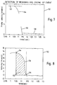
- the curve-fitting phase 34 locates in the penetration event window 50, the initiation of the penetration event 54 and the termination of the penetration event 56.
- the curve-fitting phase 34 first selects two regions within the penetration event window 50.
- the first region 58 is limited the portion of the penetration event window 50 where the velocity samples exceed eighty percent of the maximum velocity attained by the penetrometer 14 during descent.
- the second region 60 is limited to the portion of the penetration event window 50 where the velocity samples are less than twenty percent of the maximum velocity attained by the penetrometer 14 during descent. Selection of the first region 58 and the second region 60 is illustrated in Figure 6.
- the two regions of the penetration event window 50 are analyzed in terms of an empirical model.
- the model assumes that during the beginning of the penetration event 44, the upward forces acting on the penetrometer 14 increase proportionally to (time) ⁇ where ⁇ is an empirical constant. Based on that assumption, a generalized set of equations are assumed to describe the velocity of the penetrometer 14 before, during and after the penetration event 44.
- the actual initiation of the penetration event 54 is chosen as the time where the digital record 38 within the first region 58 of the penetration event window 50 most accurately fits the generalized equations.
- each possible t o in the first region 58 is examined and optimal vo , a o and b o values are selected.
- the t o that best fits the two equations is selected as the actual t o or the initiation of the penetration event 54.
- Use of the curve-fitting process may be best appreciated by reference to Figures 7 and 8.
- Figure 7 it can be seen that a line representing the first equation is shown and designated 62.
- Figure 7 also shows a curve corresponding to the second equation designated 64. It may be appreciated that the combination of the line defined by the first equation 62 and the curve defined by the second equation 64 may be used to approximate the region of the digital record 38 that contains the initiation of the penetration event 54.
- the value of t o that results in the best curve fit defines the initiation of the penetration event 54 as shown in Figure 8.
- time t1 the termination of the penetration event 56, is extracted from the second region 60 of the penetration event window 50.
- each possible t1 in the second region 60 of the penetration event window 50 is examined and optimal v1 , v2 , a1 and a2 values are selected.
- the t1 that best fits the two equations is selected as the actual t1 or the termination of the penetration event 56.
- the third equation 66 as well as the forth equation 68 may be represented by lines designated 66 and 68 respectively. More specifically, it can be seen that the termination of the penetration event 56 may be approximated by the intersection of the lines defined by equation 66 and equation 68. The approximation that results in the best curve fit defines the termination of the penetration event 56 as shown in Figure 8.
- the final phase in the data flow diagram is the integration phase 36.
- the integration phase 36 At the beginning of the integration phase 36, the initiation of the penetration event 54 and the termination of the penetration event 56 are known.
- the digital record 38 within the penetration event window 50 describes the speed of the penetrometer 14 between the initiation of the penetration event 54 and the termination of the penetration event 56.
- the depth of penetration is calculated by numerically integrating the digital record 38 starting at the initiation of the penetration event 54 and ending at termination of the penetration event 56.
- the numerical integration calculates the area under the curve represented by the digital record 38 and corresponds to the depth of penetration achieved by the penetrometer 14.
- the process of numerical integration is shown in greater detail in Figure 8 where it can be seen that the initiation of the penetration event 54 and the termination of the penetration event 56 define a bounded region of the digital record 38. It may also be seen that the result of the numerical integration calculates the area 62 under the curve defined by the digital record 38 and bounded by the initiation of the penetration event 54 and ending at termination of the penetration event 56.
- information describing the physical characteristics of the penetrometer 14 such as weight and size may be combined with the calculated depth of penetration to determine the composition of the sea floor at the point of impact.
Landscapes
- Life Sciences & Earth Sciences (AREA)
- Physics & Mathematics (AREA)
- General Physics & Mathematics (AREA)
- General Life Sciences & Earth Sciences (AREA)
- Geophysics (AREA)
- Environmental & Geological Engineering (AREA)
- Geology (AREA)
- Remote Sensing (AREA)
- Engineering & Computer Science (AREA)
- Oceanography (AREA)
- Acoustics & Sound (AREA)
- Health & Medical Sciences (AREA)
- Chemical & Material Sciences (AREA)
- Analytical Chemistry (AREA)
- Biochemistry (AREA)
- General Health & Medical Sciences (AREA)
- Immunology (AREA)
- Pathology (AREA)
- Measurement Of Mechanical Vibrations Or Ultrasonic Waves (AREA)
Applications Claiming Priority (2)
| Application Number | Priority Date | Filing Date | Title |
|---|---|---|---|
| US08/303,051 US5444670A (en) | 1994-09-08 | 1994-09-08 | Method and apparatus for determining soil strength from Doppler-shifted acoustic signatures |
| US303051 | 1994-09-08 |
Publications (2)
| Publication Number | Publication Date |
|---|---|
| EP0701147A2 true EP0701147A2 (fr) | 1996-03-13 |
| EP0701147A3 EP0701147A3 (fr) | 1997-02-05 |
Family
ID=23170335
Family Applications (1)
| Application Number | Title | Priority Date | Filing Date |
|---|---|---|---|
| EP95305841A Withdrawn EP0701147A3 (fr) | 1994-09-08 | 1995-08-22 | Procédé et dispositif pour déterminer des propriétés mécaniques du sol au moyen des signatures acoustiques décalé par l'effet Doppler |
Country Status (3)
| Country | Link |
|---|---|
| US (1) | US5444670A (fr) |
| EP (1) | EP0701147A3 (fr) |
| AU (1) | AU3051195A (fr) |
Cited By (1)
| Publication number | Priority date | Publication date | Assignee | Title |
|---|---|---|---|---|
| CN110320276A (zh) * | 2019-07-23 | 2019-10-11 | 北京领示科技有限公司 | 一种基于超声波的复合材料板冲击损伤和冲击力定量方法 |
Families Citing this family (12)
| Publication number | Priority date | Publication date | Assignee | Title |
|---|---|---|---|---|
| US5504685A (en) * | 1994-09-09 | 1996-04-02 | Sonatech, Inc. | Method and apparatus for routing an underwater cable system |
| US5805525A (en) * | 1996-12-11 | 1998-09-08 | The United States Of America As Represented By The Secretary Of The Army | Method and apparatus for hydroacoustic detection and characterization of submersed aquatic vegetation |
| US5996414A (en) * | 1997-09-09 | 1999-12-07 | North American Geotechnical Company | Method of determining the length of a pile |
| US6621860B1 (en) * | 1999-02-08 | 2003-09-16 | Advantest Corp | Apparatus for and method of measuring a jitter |
| EP1955177B1 (fr) * | 2005-11-04 | 2020-09-23 | Tektronix, Inc. | Procédés, systèmes et dispositif pour marqueurs multidomaines |
| US7637161B2 (en) * | 2006-04-19 | 2009-12-29 | Raytheon Utd Inc. | Substrate penetrating acoustic sensor |
| US7581452B2 (en) * | 2008-01-03 | 2009-09-01 | Physical Optics Corporation | System and method for soil strength measurement |
| US8994527B2 (en) * | 2009-03-19 | 2015-03-31 | Galen G. Verhulst | Sea floor sampling device and method |
| RU2673506C1 (ru) * | 2018-02-14 | 2018-11-27 | Акционерное общество "Центральное конструкторское бюро морской техники "Рубин" | Виброщуп контроля плотности грунта морского дна |
| CN110409399B (zh) * | 2019-07-01 | 2021-02-19 | 大连理工大学 | 一种软土场地土体参数横向连续测量方法 |
| CN113188936B (zh) * | 2021-03-25 | 2022-05-31 | 江苏长欣车辆装备有限公司 | 一种汽车玻璃检测用抗压强度检测装置、系统及方法 |
| CN115930852B (zh) * | 2023-01-03 | 2025-07-25 | 中国科学院西北生态环境资源研究院 | 活动层厚度估算方法、装置、存储介质及电子设备 |
Citations (1)
| Publication number | Priority date | Publication date | Assignee | Title |
|---|---|---|---|---|
| US4007633A (en) | 1975-10-14 | 1977-02-15 | The United States Of America As Represented By The Secretary Of The Navy | Method of determining the physical characteristics of a sea floor |
Family Cites Families (4)
| Publication number | Priority date | Publication date | Assignee | Title |
|---|---|---|---|---|
| US4186373A (en) * | 1978-05-22 | 1980-01-29 | The United States Of America As Represented By The Secretary Of The Navy | System for measuring in situ acoustic energy properties of ocean floor soils |
| US4382384A (en) * | 1981-06-15 | 1983-05-10 | The Regents Of The University Of California | Acoustic penetrometer for subsoil investigation |
| US4608993A (en) * | 1984-07-31 | 1986-09-02 | Quinton Instrument Company | Blood flow measurement device and method |
| SU1437284A1 (ru) * | 1986-12-26 | 1988-11-15 | Московский Институт Инженеров Железнодорожного Транспорта | Устройство дл измерени ускорени движени отцепов на сортировочной горке |
-
1994
- 1994-09-08 US US08/303,051 patent/US5444670A/en not_active Expired - Fee Related
-
1995
- 1995-08-22 EP EP95305841A patent/EP0701147A3/fr not_active Withdrawn
- 1995-09-07 AU AU30511/95A patent/AU3051195A/en not_active Abandoned
Patent Citations (1)
| Publication number | Priority date | Publication date | Assignee | Title |
|---|---|---|---|---|
| US4007633A (en) | 1975-10-14 | 1977-02-15 | The United States Of America As Represented By The Secretary Of The Navy | Method of determining the physical characteristics of a sea floor |
Cited By (1)
| Publication number | Priority date | Publication date | Assignee | Title |
|---|---|---|---|---|
| CN110320276A (zh) * | 2019-07-23 | 2019-10-11 | 北京领示科技有限公司 | 一种基于超声波的复合材料板冲击损伤和冲击力定量方法 |
Also Published As
| Publication number | Publication date |
|---|---|
| AU3051195A (en) | 1996-03-21 |
| US5444670A (en) | 1995-08-22 |
| EP0701147A3 (fr) | 1997-02-05 |
Similar Documents
| Publication | Publication Date | Title |
|---|---|---|
| US5444670A (en) | Method and apparatus for determining soil strength from Doppler-shifted acoustic signatures | |
| US6581014B2 (en) | Apparatus and method for analysis of guided ultrasonic waves | |
| EP0288578A1 (fr) | Procede et appareil de detection d'objets | |
| CN102736081A (zh) | 水中探测装置、鱼群探测机、水中探测方法以及程序 | |
| EP0156636B1 (fr) | Traitement de signaux écho | |
| US5635632A (en) | Settling process analysis device and method | |
| Beard | A penetrometer for deep ocean seafloor exploration | |
| EP1780539A1 (fr) | Procédé et appareil pour l'essai non-destructif ultrasonore de structures en béton | |
| US20070095139A1 (en) | Method and apparatus for non-destructive testing of concrete structures | |
| ATE169742T1 (de) | Verfahren und vorrichtung zur zerstörungsfreien prüfung von gegenständen mit ultraschall | |
| CA1153815A (fr) | Appareil et methode de determination de la vitesse des ondes acoustiques dans les formations geologiques | |
| US5789676A (en) | Settling process analysis device and method | |
| US4367541A (en) | Apparatus and method for determining velocity of acoustic waves in earth formations | |
| Kraft et al. | Calculation of in situ acoustic wave properties in marine sediments | |
| JP3881078B2 (ja) | 周波数推定方法、周波数推定装置、ドップラソナーおよび潮流計 | |
| JP2000180561A (ja) | 地盤調査方法 | |
| Hong et al. | An effective method for measuring the thickness of Cobalt-rich Manganese Crust based on the neighborhood information and dual-channel information | |
| Martin et al. | Signal processing of leaky Lamb wave data for defect imaging in composite laminates | |
| Elsley et al. | Dependence of the accuracy of the Born inversion on noise and bandwidth | |
| Douglas et al. | Test results of the doppler penetrometer seafloor sediment profiling system | |
| CA2077387C (fr) | Methode permettant de determiner la vitesse et le niveau de fiabilite d'ondes acoustiques en sol penetrables | |
| SU900236A1 (ru) | Аппаратура дл структурно-литологического картировани донных отложений | |
| Bhagat et al. | Effects of deconvolution procedures on size estimates in the Born inversion algorithm | |
| Ingram | Expendable penetrometer for seafloor classification | |
| CN119805547A (zh) | 一种基于水上地震探测的双气泡震源监控方法 |
Legal Events
| Date | Code | Title | Description |
|---|---|---|---|
| PUAI | Public reference made under article 153(3) epc to a published international application that has entered the european phase |
Free format text: ORIGINAL CODE: 0009012 |
|
| AK | Designated contracting states |
Kind code of ref document: A2 Designated state(s): DE FR GB NL |
|
| PUAL | Search report despatched |
Free format text: ORIGINAL CODE: 0009013 |
|
| AK | Designated contracting states |
Kind code of ref document: A3 Designated state(s): DE FR GB NL |
|
| STAA | Information on the status of an ep patent application or granted ep patent |
Free format text: STATUS: THE APPLICATION IS DEEMED TO BE WITHDRAWN |
|
| 18D | Application deemed to be withdrawn |
Effective date: 19970806 |