EP0700815A2 - Electronically controlled brake booster with cable lead-through - Google Patents
Electronically controlled brake booster with cable lead-through Download PDFInfo
- Publication number
- EP0700815A2 EP0700815A2 EP95112940A EP95112940A EP0700815A2 EP 0700815 A2 EP0700815 A2 EP 0700815A2 EP 95112940 A EP95112940 A EP 95112940A EP 95112940 A EP95112940 A EP 95112940A EP 0700815 A2 EP0700815 A2 EP 0700815A2
- Authority
- EP
- European Patent Office
- Prior art keywords
- brake booster
- movable wall
- booster according
- seal
- section
- Prior art date
- Legal status (The legal status is an assumption and is not a legal conclusion. Google has not performed a legal analysis and makes no representation as to the accuracy of the status listed.)
- Granted
Links
- 230000000149 penetrating effect Effects 0.000 claims abstract 2
- 239000012528 membrane Substances 0.000 claims description 14
- 239000011324 bead Substances 0.000 claims description 8
- 238000005096 rolling process Methods 0.000 claims description 8
- 239000000463 material Substances 0.000 claims description 7
- 238000007789 sealing Methods 0.000 claims description 5
- 238000002788 crimping Methods 0.000 claims description 4
- 238000005192 partition Methods 0.000 claims description 4
- 238000005476 soldering Methods 0.000 claims description 3
- 238000009434 installation Methods 0.000 abstract description 2
- 230000008878 coupling Effects 0.000 description 1
- 238000010168 coupling process Methods 0.000 description 1
- 238000005859 coupling reaction Methods 0.000 description 1
- 230000000694 effects Effects 0.000 description 1
- 239000003365 glass fiber Substances 0.000 description 1
- 238000004519 manufacturing process Methods 0.000 description 1
- 239000002184 metal Substances 0.000 description 1
- 239000013307 optical fiber Substances 0.000 description 1
- 230000008054 signal transmission Effects 0.000 description 1
- 229920003002 synthetic resin Polymers 0.000 description 1
- 239000000057 synthetic resin Substances 0.000 description 1
Images

Classifications
-
- H—ELECTRICITY
- H01—ELECTRIC ELEMENTS
- H01R—ELECTRICALLY-CONDUCTIVE CONNECTIONS; STRUCTURAL ASSOCIATIONS OF A PLURALITY OF MUTUALLY-INSULATED ELECTRICAL CONNECTING ELEMENTS; COUPLING DEVICES; CURRENT COLLECTORS
- H01R13/00—Details of coupling devices of the kinds covered by groups H01R12/70 or H01R24/00 - H01R33/00
- H01R13/73—Means for mounting coupling parts to apparatus or structures, e.g. to a wall
- H01R13/74—Means for mounting coupling parts in openings of a panel
-
- B—PERFORMING OPERATIONS; TRANSPORTING
- B60—VEHICLES IN GENERAL
- B60T—VEHICLE BRAKE CONTROL SYSTEMS OR PARTS THEREOF; BRAKE CONTROL SYSTEMS OR PARTS THEREOF, IN GENERAL; ARRANGEMENT OF BRAKING ELEMENTS ON VEHICLES IN GENERAL; PORTABLE DEVICES FOR PREVENTING UNWANTED MOVEMENT OF VEHICLES; VEHICLE MODIFICATIONS TO FACILITATE COOLING OF BRAKES
- B60T13/00—Transmitting braking action from initiating means to ultimate brake actuator with power assistance or drive; Brake systems incorporating such transmitting means, e.g. air-pressure brake systems
- B60T13/10—Transmitting braking action from initiating means to ultimate brake actuator with power assistance or drive; Brake systems incorporating such transmitting means, e.g. air-pressure brake systems with fluid assistance, drive, or release
- B60T13/24—Transmitting braking action from initiating means to ultimate brake actuator with power assistance or drive; Brake systems incorporating such transmitting means, e.g. air-pressure brake systems with fluid assistance, drive, or release the fluid being gaseous
- B60T13/46—Vacuum systems
- B60T13/52—Vacuum systems indirect, i.e. vacuum booster units
- B60T13/569—Vacuum systems indirect, i.e. vacuum booster units characterised by piston details, e.g. construction, mounting of diaphragm
-
- B—PERFORMING OPERATIONS; TRANSPORTING
- B60—VEHICLES IN GENERAL
- B60T—VEHICLE BRAKE CONTROL SYSTEMS OR PARTS THEREOF; BRAKE CONTROL SYSTEMS OR PARTS THEREOF, IN GENERAL; ARRANGEMENT OF BRAKING ELEMENTS ON VEHICLES IN GENERAL; PORTABLE DEVICES FOR PREVENTING UNWANTED MOVEMENT OF VEHICLES; VEHICLE MODIFICATIONS TO FACILITATE COOLING OF BRAKES
- B60T13/00—Transmitting braking action from initiating means to ultimate brake actuator with power assistance or drive; Brake systems incorporating such transmitting means, e.g. air-pressure brake systems
- B60T13/10—Transmitting braking action from initiating means to ultimate brake actuator with power assistance or drive; Brake systems incorporating such transmitting means, e.g. air-pressure brake systems with fluid assistance, drive, or release
- B60T13/66—Electrical control in fluid-pressure brake systems
- B60T13/72—Electrical control in fluid-pressure brake systems in vacuum systems or vacuum booster units
Definitions
- the present invention relates to an electronically controllable brake booster with a line bushing with the features of the preamble of claim 1, as is known from US 4,944,214.
- the actuating devices present in the electronically controllable brake booster are supplied with current or control signals via an electronic control unit arranged in the engine compartment of the vehicle, and sensors arranged in the brake booster deliver signals which are sent to the electronic control unit for further processing.
- the present invention is therefore based on the problem of passing an electrical line through the movable wall between the two pneumatic working chambers of the brake booster, with the aim of ensuring simple assembly and high reliability of the arrangement during operation.
- This arrangement has the unexpected effect that, despite the axial movement of the wall between the two working chambers, hermetic passage of the line from one working chamber to the next is possible, with no (time) losses when building up the pressure difference between the two pneumatic working chambers occur through air flowing through the duct.
- An electrical line in the sense of the present invention is understood to mean both a metallic cable and a glass fiber cable for the transmission of signals.
- the seal is formed in one piece with a roller membrane connected to a part of the movable wall.
- the seal preferably has a web with a material thickness that is greater than the rest of the rolling membrane in order to keep the section of the line leadthrough projecting through the movable wall in a defined position, so that even when the movable wall is moved by cables leading out of the line leadthrough, no significant lateral movement Tensile forces can be caused, which could cause the line bushing to slip in the seal and thereby cause the overall arrangement to leak.
- the seal preferably has a bead which at least partially surrounds the holder in order to further improve the stable reception of the line bushing.
- the bead forms a step with the web, in which the holder is at least partially received.
- the cable routing is preferably accommodated in the seal so that it cannot rotate.
- This can be achieved, for example, in that the bead and / or the web have a recess into which a correspondingly shaped part of the line bushing engages.
- the seal surrounds the line leadthrough in the sliding seat with its area surrounding the section projecting through the movable wall, the line leadthrough can be installed in the seal relatively easily.
- the area of the seal surrounding the section projecting through the movable wall has at least one sealing lip. This can securely enclose the cable duct and thus hermetically separate the two working chambers.
- a fastening element can be brought into engagement with the section protruding through the movable wall, so that the line bushing is captively connected to the seal.
- the fastening element and the section projecting through the movable wall preferably each have at least one recess or at least one projection which engages in the respective recess.
- the recess and the projection can then be designed so that they can be locked together.
- the fastening element presses the seal in its assembled position - the recess or the projection are locked together - against the holder.
- the section protruding through the movable wall and / or the holder are preferably of sleeve-shaped, in particular essentially cylindrical. A particularly dense arrangement is thus achieved.
- the cable bushing has at least one connecting pin, the two ends of which protrude beyond a partition arranged in the cable bushing.
- at least one end of the connecting pins is set back relative to an end face of the section or the holder protruding through the movable wall.
- the ends of the connector pin are electrically connected with a connecting cable. If the line is designed as an optical fiber line, a corresponding line coupling can also be provided here.
- the connecting pin (possibly together with the connecting cable electrically connected to it) is preferably surrounded by a hermetically hardening metal.
- the electrical connection from the first working chamber to the second working chamber between one end of the connector pin and the connecting cable can be produced by soldering, crimping, squeezing or by a plug connection.
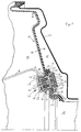
- FIG. 1 shows part of an electronically controllable brake booster which has a first pneumatic working chamber 11 and a second pneumatic working chamber 12, which are separated from one another by a movable wall 13.
- the movable wall has a rigid part 14 in the form of a circular force-transmitting membrane plate, which is connected to a rolling membrane 16 made of a rubber-like material.
- the roller membrane 16 projects beyond the membrane plate along its circumference in the radial direction and is hermetically connected to a housing shell 17 which is only partially illustrated.
- the two parts are connected to a control housing 18 of a control valve arrangement (not illustrated further).
- the diaphragm plate 14 In the radial direction close to the control housing 18, the diaphragm plate 14 has a circular opening 19 which is aligned with an opening 21 with essentially the same diameter.
- the rolling membrane 16 In the area surrounding the opening 21, the rolling membrane 16 is provided with a web 22 which has a material thickness which is approximately doubled compared to the remaining rolling membrane 16, as a result of which a seal 22 is formed.
- the seal On the side of the seal facing away from the diaphragm plate 14, the seal has a bead 23 which has an inner diameter that is larger than that of the opening 21 has, so that the web 22 forms a step 24 together with the bead 23.
- a line bushing, generally designated 26, has an essentially cylindrical cross-sectional shape and has a section 27 projecting through the movable wall 14 in the region of the opening 19 and through the web 22 of the seal in the region of the opening 21, the free end 28 of which extends into the second pneumatic one Working chamber 12 protrudes.
- the line bushing 26 has a holder 29 which is integrally formed on the section 28 and has an enlarged diameter relative to the latter, which is dimensioned such that the holder 29 is received in the step 24.
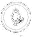
- the bead 23 has a radial recess into which a radial extension 31 integrally formed on the holder engages in a form-fitting manner (see FIG. 2).
- the line bushing 26 is received with its section 27 projecting through the movable wall 14 in the region of the opening 21, which surrounds the section 27, in a sliding fit.
- the seal 22 has a circumferential sealing lip 32 in the region of the opening 21 which faces the section 27 (see FIG. 3).
- the line bushing 26 has a fastening element in the form of a cap 33 with a profile which is essentially U-shaped in longitudinal section.
- a circumferential projection 34 which acts as a detent and which engages in a recess 35 formed on the outside of the cylindrical section 27.
- the projection 34 is provided with an inclined ramp 36 and an edge 37 extending at right angles to the inner wall.
- the free end 28 of the section 27 of the line bushing 26 is chamfered on its outside, so that the cap 35 over the section 27 against the membrane plate 14 can be pushed so that the recess 35 and the projection 34 can latch together.
- the dimensions of the recess 35 and the projection 34 and the cap 33 and the longitudinal extent of the section 27 relative to the holder 29 and the material thickness of the web 22 are dimensioned such that, in one embodiment, the line bushing 26 with little axial play - through the cap 33 and the holder 29 limited - is received in the opening 19 or 21, while in a second embodiment of the fastening element 33, the seal 22 presses against the holder 29.
- the line bushing 26 has three connecting pins 40a, 40b, 40c, the respective two ends 42, 43 of which project beyond a partition 45 arranged in the cable bushing.
- the connection pins 40a, 40b, 40c are hermetically arranged in the partition and at the end 42 of the connection pins 40a, 40b, 40c located in the holder 29, these are set back relative to the end face of the holder 29.
- the ends 43 of the connecting pins 40a, 40b, 40c practically extend to the end face of the end 28 of the section 27.
- each connecting pin 40a, 40b, 40c is connected to a wire of a cable A, B by soldering, crimping, crimping or a plug connection, so that an electrical connection from the first working chamber to the second working chamber is made by the Cable bushing is made.
- the respective electrical connection from the wires of the connecting cables A, B to the ends of the connecting pins 40a, 40b, 40c is surrounded by a hermetically hardening (synthetic resin) material, whereby the sealing is further improved.
- a major advantage of the invention is that the seal can be part of the movable wall, in particular part of the rolling membrane. This means that due to the special design of the rolling membrane in the area of the cable duct, several functions are integrated with one another. This allows a particularly simple and inexpensive installation.
Abstract
Um bei einem elektronisch regelbaren Bremskraftverstärker, der eine erste pneumatische Arbeitskammer (11) und eine zweite pneumatische Arbeitskammer (12) aufweist, die voneinander durch eine bewegliche Wand (13) getrennt sind, eine elektrische Leitung durch die bewegliche Wand zwischen den beiden pneumatischen Arbeitskammern hindurchzuführen, wobei eine einfache Montage und eine hohe Zuverlässigkeit der Gesamtanordnung im Betrieb gewährleistet sein soll, ist eine die bewegliche Wand durchdringende Leitungsdurchführung (26) für wenigstens eine elektrische Leitung, mit einem durch die bewegliche Wand hindurchragenden Abschnitt (27) der Leitungsdurchführung, und einer Halterung (29), die die Beweglichkeit der Leitungsdurchführung zumindest in deren Längsrichtung begrenzt, und eine die Leitungsdurchführung im Bereich der beweglichen Wand umgebende Dichtung (22) vorgesehen.In the case of an electronically controllable brake booster which has a first pneumatic working chamber (11) and a second pneumatic working chamber (12), which are separated from one another by a movable wall (13), an electrical line is passed through the movable wall between the two pneumatic working chambers A simple installation and high reliability of the overall arrangement during operation is to be ensured, is a cable bushing (26) penetrating the movable wall for at least one electrical cable, with a section (27) of the cable bushing projecting through the movable wall, and a holder (29), which limits the mobility of the cable duct at least in its longitudinal direction, and a seal (22) surrounding the cable duct in the region of the movable wall.
Description
Die vorliegende Erfindung betrifft einen elektronisch regelbaren Bremskraftverstärker mit einer Leitungsdurchführung mit den Merkmalen des Oberbegriffs des Anspruchs 1, wie er aus der US 4,944,214 bekannt ist.The present invention relates to an electronically controllable brake booster with a line bushing with the features of the preamble of claim 1, as is known from US 4,944,214.
Die in dem elektronisch regelbaren Bremskraftverstärker vorhandenen Betätigungseinrichtungen werden über ein im Motorraum des Fahrzeugs angeordnetes elektronisches Steuergerät mit Strom- bzw. Ansteuersignalen versorgt und in dem Bremskraftverstärker angeordnete Sensoren liefern Signale, die an das elektronische Steuergerät zur weiteren Verarbeitung geleitet werden.The actuating devices present in the electronically controllable brake booster are supplied with current or control signals via an electronic control unit arranged in the engine compartment of the vehicle, and sensors arranged in the brake booster deliver signals which are sent to the electronic control unit for further processing.
Dies erfordert eine aufwendige Verkabelung zwischen dem elektronischen Steuergerät und den einzelnen Verbrauchern bzw. Signalquellen in dem Bremskraftverstärker. Eine Anordnung der Leitungen außerhalb des Bremskraftverstärkers ist unter anderem deshalb nachteilig, weil die Leitungen dabei relativ stabil und widerstandsfähig ausgestaltet sein müssen.This requires complex wiring between the electronic control unit and the individual consumers or signal sources in the brake booster. An arrangement of the lines outside the brake booster is disadvantageous, among other things, because the lines must be made relatively stable and resistant.
Andererseits ist die Leitungsdurchführung zu einzelnen Verbrauchern oder Quellen durch die verschiedenen Arbeitskammern des Bremskraftverstärkers hindurch schon deshalb nicht realisiert worden, weil die einzelnen Durchtrittsstellen durch die Wände der Arbeitskammern sowohl pneumatisch dicht sein müssen, als auch der Durchtritt durch die bewegliche Wand zwischen den beiden Arbeitskammern relativ problematisch ist, da die Druckverhältnisse zwischen den beiden Arbeitskammern schwanken und die Wand zwischen den beiden Arbeitskammern sich im Betrieb der Fahrzeugbremsanlage bewegt.On the other hand, the line routing to individual consumers or sources through the various working chambers of the brake booster has not been implemented because the individual passage points through the walls of the working chambers must be both pneumatically tight and the passage through the movable wall between the two working chambers is relative is problematic because the pressure conditions between the two working chambers fluctuate and the Wall between the two working chambers moves during operation of the vehicle brake system.
Der vorliegenden Erfindung liegt daher das Problem zugrunde, eine elektrische Leitung durch die bewegliche Wand zwischen den beiden pneumatischen Arbeitskammern des Bremskraftverstärkers hindurchzuführen, wobei eine einfache Montage und eine hohe Zuverlässigkeit der Anordnung im Betrieb gewährleistet werden soll.The present invention is therefore based on the problem of passing an electrical line through the movable wall between the two pneumatic working chambers of the brake booster, with the aim of ensuring simple assembly and high reliability of the arrangement during operation.
Zur Lösung dieses Problems ist der eingangs beschriebene Bremskraftverstärker durch die Merkmale des Anspruchs 1 weitergebildet.To solve this problem, the brake booster described at the outset is developed by the features of claim 1.
Durch diese Anordnung wird der unerwartete Effekt erzielt, daß trotz der axialen Bewegung der Wand zwischen den beiden Arbeitskammern ein hermetischer Durchgriff der Leitung von einer Arbeitskammer in die nächste möglich ist, wobei beim Aufbau der Druckdifferenz zwischen den beiden pneumatischen Arbeitskammern keine (Zeit-)Verluste durch neben der Leitungsdurchführung hindurchströmende Luft auftreten.This arrangement has the unexpected effect that, despite the axial movement of the wall between the two working chambers, hermetic passage of the line from one working chamber to the next is possible, with no (time) losses when building up the pressure difference between the two pneumatic working chambers occur through air flowing through the duct.
Unter einer elektrischen Leitung im Sinne der vorliegenden Erfindung ist sowohl ein metallisches Kabel als auch ein Glasfaserkabel zur Übertragung von Signalen zu verstehen.An electrical line in the sense of the present invention is understood to mean both a metallic cable and a glass fiber cable for the transmission of signals.
Da zwischen den beiden pneumatischen Arbeitskammern zumindest im Betrieb eine Druckdifferenz vorhanden ist, bewirkt eine Anordnung der Leitungsdurchführung in der Weise, daß die Halterung sich in der pneumatischen Arbeitskammer mit dem höheren Druckniveau befindet, daß eine besonders betriebssichere Anordnung bereitgestellt wird.Since there is a pressure difference between the two pneumatic working chambers, at least during operation, arranging the line leadthrough in such a way that the holder is located in the pneumatic working chamber with the higher pressure level, so that a particularly reliable arrangement is provided.
Gemäß einer besonders einfach herstellbaren Ausführungsform ist die Dichtung mit einer mit einem Teil der beweglichen Wand verbundenen Rollmembran einstückig ausgebildet.According to a particularly simple to manufacture embodiment, the seal is formed in one piece with a roller membrane connected to a part of the movable wall.
Dabei hat vorzugsweise die Dichtung einen Steg mit einer gegenüber der übrigen Rollmembran größeren Materialdicke, um den durch die bewegliche Wand hindurchragenden Abschnitt der Leitungsdurchführung in einer definierten Position zu halten, so daß auch bei Bewegungen der beweglichen Wand durch an der Leitungsdurchführung abgehende Kabel keine nennenswerten seitlichen Zugkräfte hervorgerufen werden können, die zu einem Verrutschen der Leitungsdurchführung in der Dichtung führen und dadurch eine Undichtigkeit der Gesamtanordnung hervorrufen könnten.The seal preferably has a web with a material thickness that is greater than the rest of the rolling membrane in order to keep the section of the line leadthrough projecting through the movable wall in a defined position, so that even when the movable wall is moved by cables leading out of the line leadthrough, no significant lateral movement Tensile forces can be caused, which could cause the line bushing to slip in the seal and thereby cause the overall arrangement to leak.
Vorzugsweise hat die Dichtung einen die Halterung zumindest teilweise umgebenden Wulst, um die stabile Aufnahme der Leitungsdurchführung noch weiter zu verbessern. Bei einer bevorzugten Ausführungsform bildet der Wulst mit dem Steg eine Stufe, in der die Halterung zumindest teilweise aufgenommen ist.The seal preferably has a bead which at least partially surrounds the holder in order to further improve the stable reception of the line bushing. In a preferred embodiment, the bead forms a step with the web, in which the holder is at least partially received.
Um eine möglichst definierte Leitungsführung im Inneren des Bremskraftverstärkers zu erreichen, und um eine möglichst einfache Montage zu ermöglichen, ist die Leitungsdurchführung in der Dichtung vorzugsweise verdrehsicher aufgenommen. Dies kann beispielsweise dadurch erreicht werden, daß der Wulst und/oder der Steg eine Ausnehmung aufweisen, in die ein entsprechend geformter Teil der Leitungsdurchführung eingreift.In order to achieve the most possible defined cable routing inside the brake booster and to enable the simplest possible assembly, the cable routing is preferably accommodated in the seal so that it cannot rotate. This can be achieved, for example, in that the bead and / or the web have a recess into which a correspondingly shaped part of the line bushing engages.
Wenn die Dichtung mit ihrem den durch die bewegliche Wand hindurchragenden Abschnitt umgebenden Bereich die Leitungsdurchführung im Schiebesitz umgreift, kann die Leitungsdurchführung in der Dichtung relativ einfach montiert werden. Um besonders definierte Dichtverhältnisse zu haben, ist es vorteilhaft, wenn der den durch die bewegliche Wand hindurchragende Abschnitt umgebende Bereich der Dichtung wenigstens eine Dichtlippe aufweist. Diese kann die Leitungsdurchführung sicher umschließen und so die beiden Arbeitskammern hermetisch voneinander trennen.If the seal surrounds the line leadthrough in the sliding seat with its area surrounding the section projecting through the movable wall, the line leadthrough can be installed in the seal relatively easily. In order to have particularly defined sealing conditions, it is advantageous if the area of the seal surrounding the section projecting through the movable wall has at least one sealing lip. This can securely enclose the cable duct and thus hermetically separate the two working chambers.
Zur Erhöhung der Betriebssicherheit ist es darüber hinaus vorteilhaft, wenn ein Befestigungselement mit dem durch die bewegliche Wand hindurchragenden Abschnitt in Eingriff bringbar ist, so daß die Leitungsdurchführung mit der Dichtung unverlierbar verbunden ist.To increase operational safety, it is also advantageous if a fastening element can be brought into engagement with the section protruding through the movable wall, so that the line bushing is captively connected to the seal.
Vorzugsweise hat das Befestigungselement und der durch die bewegliche Wand hindurchragende Abschnitt jeweils wenigstens eine Ausnehmung bzw. wenigstens einen in die jeweilige Ausnehmung eingreifenden Vorsprung. Die Ausnehmung und der Vorsprung können dann miteinander verrastbar ausgestaltet sein. Es ist jedoch auch möglich, eine Verschraubung oder eine Bajonett-Verriegelung zwischen den die bewegliche Wand durchragenden Abschnitt und dem Befestigungselment zu versehen. Bei einer bevorzugten Ausführungsform preßt das Befestigungselement die Dichtung in seiner montierten Stellung - die Ausnehmung bzw. der Vorsprung sind miteinander verrastet - gegen die Halterung.The fastening element and the section projecting through the movable wall preferably each have at least one recess or at least one projection which engages in the respective recess. The recess and the projection can then be designed so that they can be locked together. However, it is also possible to provide a screw connection or a bayonet lock between the section protruding through the movable wall and the fastening element. In a preferred embodiment, the fastening element presses the seal in its assembled position - the recess or the projection are locked together - against the holder.
Vorzugsweise sind der durch die bewegliche Wand hindurchragende Abschnitt und/oder die Halterung hülsenförmig, insbesondere im wesentlichen zylindrisch gestaltet. Damit wird eine besonders dichte Anordnung erreicht.The section protruding through the movable wall and / or the holder are preferably of sleeve-shaped, in particular essentially cylindrical. A particularly dense arrangement is thus achieved.
Die Leitungsdurchführung weist wenigstens einen Anschlußstift auf, dessen beide Enden eine in der Leitungsdurchführung angeordnete Trennwand überragen. Vorzugsweise ist wenigstens ein Ende des Anschlußstifte gegenüber einer Stirnseite des durch die bewegliche Wand hindurchragenden Abschnitts bzw. der Halterung zurückversetzt. Die Enden des Anschlußstiftes sind mit einem Anschlußkabel elektrisch verbunden. Falls die Leitung als Glasfaserleitung ausgestaltet ist, kann hier auch eine entsprechende Leitungskupplung vorgesehen sein.The cable bushing has at least one connecting pin, the two ends of which protrude beyond a partition arranged in the cable bushing. Preferably, at least one end of the connecting pins is set back relative to an end face of the section or the holder protruding through the movable wall. The ends of the connector pin are electrically connected with a connecting cable. If the line is designed as an optical fiber line, a corresponding line coupling can also be provided here.
Der Anschlußstift (ggf. zusammen mit dem damit elektrisch verbundenen Anschlußkabel) ist vorzugsweise mit einem hermetisch aushärtenden Metall umgeben.The connecting pin (possibly together with the connecting cable electrically connected to it) is preferably surrounded by a hermetically hardening metal.
Die elektrische Verbindung von der ersten Arbeitskammer zu der zweiten Arbeitskammer zwischen einem Ende des Anschlußstifts und dem Anschlußkabel kann durch Löten, Crimpen, Quetschen oder durch eine Steckverbindung hergestellt sein.The electrical connection from the first working chamber to the second working chamber between one end of the connector pin and the connecting cable can be produced by soldering, crimping, squeezing or by a plug connection.
Weitere Vorteile und Ausgestaltungen werden anhand der nachstehenden Figurenbeschreibung unter Bezugnahme auf die beigefügten Zeichnungen erläutert, in denen:
- Fig. 1
- einen Längsschnitt eines Bremskraftverstärkers in einer Teilansicht zeigt;
- Fig. 2
- eine Draufsicht auf eine in Fig. 1 dargestellte bewegliche Wand in einem kleineren Maßstab zeigt; und
- Fig. 3
- eine in einer mit der beweglichen Wand verbundenen Rollmembran ausgebildete Dichtung in einer vergrößerten Schnittdarstellung zeigt.
- Fig. 1
- shows a longitudinal section of a brake booster in a partial view;
- Fig. 2
- a plan view of a movable wall shown in Figure 1 shows on a smaller scale; and
- Fig. 3
- shows a seal formed in a roller membrane connected to the movable wall in an enlarged sectional view.
In Fig. 1 ist ein Teil eines elektronisch regelbaren Bremskraftverstärkers gezeigt, der eine erste pneumatische Arbeitskammer 11 und eine zweite pneumatische Arbeitskammer 12 aufweist, die voneinander durch eine bewegliche Wand 13 getrennt sind. Die bewegliche Wand weist ein starres Teil 14 in Gestalt eines kreisrunden kraftübertragenden Membrantellers auf, der mit einer aus einem gummiähnlichen Material bestehenden Rollmembran 16 verbunden ist. Die Rollmembran 16 überragt den Membranteller entlang dessen Umfangs in radialer Richtung und ist mit einer nur teilweise veranschaulichten Gehäuseschale 17 hermetisch verbunden. In der Mitte des Membrantellers 14 und der Rollmembran 16 sind die beiden Teile mit einem Steuergehäuse 18 einer - nicht weiter veranschaulichten - Steuerventilanordnung verbunden.1 shows part of an electronically controllable brake booster which has a first
In radialer Richtung nahe bei dem Steuergehäuse 18 weist der Membranteller 14 eine kreisrunde Öffnung 19 auf, die mit einer Öffnung 21 mit im wesentlichen gleichen Durchmessern fluchtet. In dem die Öffnung 21 umgebenden Bereich ist die Rollmembran 16 mit einem Steg 22 versehen, der eine gegenüber der übrigen Rollmembran 16 etwa verdoppelte Materialdicke aufweist, wodurch eine Dichtung 22 gebildet ist. Auf der dem Membranteller 14 abgewandten Seite der Dichtung weist diese einen Wulst 23 auf, der einen gegenüber der Öffnung 21 vergrößerten Innendurchmesser hat, so daß der Steg 22 zusammen mit dem Wulst 23 eine Stufe 24 bildet.In the radial direction close to the
Eine allgemein mit 26 bezeichnete Leitungsdurchführung hat eine im wesentlichen zylindrische Querschnittsgestalt und weist einen durch die bewegliche Wand 14 im Bereich der Öffnung 19 sowie durch den Steg 22 der Dichtung im Bereich der Öffnung 21 hindurchragenden Abschnitt 27 auf, dessen freies Ende 28 in die zweite pneumatische Arbeitskammer 12 ragt. Am gegenüberliegenden Ende des Abschnitts 27 weist die Leitungsdurchführung 26 eine Halterung 29 auf, die einstückig an den Abschnitt 28 angeformt ist, und gegenüber diesem einen vergrößerten Durchmesser aufweist, der so bemessen ist, daß die Halterung 29 in der Stufe 24 aufgenommen ist.A line bushing, generally designated 26, has an essentially cylindrical cross-sectional shape and has a
Damit die Leitungsdurchführung 26 in der Dichtung 22 verdrehsicher aufgenommen ist, weist der Wulst 23 eine radiale Ausnehmung auf, in die ein an der Halterung angeformter radialer Fortsatz 31 formschlüssig eingreift (siehe dazu Fig. 2).In order for the line bushing 26 to be received in the
Die Leitungsdurchführung 26 ist mit ihrem durch die bewegliche Wand 14 hindurchragenden Abschnitt 27 im Bereich der Öffnung 21, die den Abschnitt 27 umgibt, in Schiebesitz aufgenommen. Dazu hat die Dichtung 22 im Bereich der Öffnung 21, der dem Abschnitt 27 zugewandt ist, eine umlaufende Dichtlippe 32 (siehe Fig. 3).The line bushing 26 is received with its
Die Leitungsdurchführung 26 weist an ihrem in die zweite pneumatische Arbeitskammer 12 ragenden Ende 28 ein Befestigungselement in Form einer Kappe 33 mit einem im Längsschnitt im wesentlichen U-förmigen Profil auf. An der Innenseite der zylindrischen Kappe 33 befindet sich ein umlaufender als Rast wirkender Vorsprung 34, der in eine an der Außenseite des zylinderförmigen Abschnitts 27 ausgeformte Ausnehmung 35 eingreift. Dabei ist der Vorsprung 34 mit einer schrägverlaufenden Auflauframpe 36 versehen und einer rechtwinklig zur Innenwand verlaufenden Kante 37. Das freie Ende 28 des Abschnitts 27 der Leitungsdurchführung 26 ist an seiner Außenseite angeschrägt, so daß die Kappe 35 über den Abschnitt 27 gegen den Membranteller 14 geschoben werden kann, so daß die Ausnehmung 35 und der Vorsprung 34 miteinander verrasten können. Dabei sind die Abmessungen der Ausnehmung 35 und des Vorsprungs 34 sowie der Kappe 33 und der Längserstreckung des Abschnitts 27 gegenüber der Halterung 29 und die Materialdicke des Steges 22 so bemessen, daß bei einer Ausführungsform die Leitungsdurchführung 26 mit geringem axialen Spiel - durch die Kappe 33 und die Halterung 29 begrenzt - in der Öffnung 19 bzw. 21 aufgenommen ist, während bei einer zweiten Ausführungsform des Befestigungselements 33 die Dichtung 22 gegen die Halterung 29 preßt.At its
Die Leitungsdurchführung 26 weist im gezeigten Ausführungsbeispiel (siehe Fig. 2) drei Anschlußstifte 40a, 40b, 40c auf, deren jeweilige beide Enden 42, 43 eine in der Leitungsdurchführung angeordnete Trennwand 45 überragen. Die Anschlußstifte 40a, 40b, 40c sind in der Trennwand hermetisch angeordnet und an dem in der Halterung 29 befindlichen Ende 42 der Anschlußstifte 40a, 40b, 40c sind diese gegenüber der Stirnseite der Halterung 29 zurückversetzt. An dem gegenüberliegenden Ende reichen die Enden 43 der Anschlußstifte 40a, 40b, 40c praktisch bis zu der Stirnseite des Endes 28 des Abschnitts 27.In the exemplary embodiment shown (see FIG. 2), the line bushing 26 has three connecting pins 40a, 40b, 40c, the respective two
An den jeweiligen beiden Enden 42, 43 ist jeder Anschlußstift 40a, 40b, 40c mit einer Ader eines Kabels A, B durch Löten, Crimpen, Quetschen oder eine Steckverbindung verbunden, so daß eine elektrische Verbindung von der ersten Arbeitskammer zu der zweiten Arbeitskammer durch die Leitungsdurchführung hergestellt ist.At the respective two ends 42, 43, each connecting pin 40a, 40b, 40c is connected to a wire of a cable A, B by soldering, crimping, crimping or a plug connection, so that an electrical connection from the first working chamber to the second working chamber is made by the Cable bushing is made.
Die jeweilige elektrische Verbindung von den Adern der Anschlußkabel A, B mit den Enden der Anschlußstifte 40a, 40b, 40c ist mit einem hermetisch aushärtenden (Kunstharz-)Material umgeben, wodurch die Abdichtung noch weiter verbessert ist.The respective electrical connection from the wires of the connecting cables A, B to the ends of the connecting pins 40a, 40b, 40c is surrounded by a hermetically hardening (synthetic resin) material, whereby the sealing is further improved.
Ein wesentlicher Vorteil der Erfindung besteht darin, daß die Dichtung ein Teil der beweglichen Wand, insbesondere ein Teil der Rollmembran sein kann. Das heißt, daß durch die besondere Gestaltung der Rollmembran im Bereich der Leitungsdurchführung mehrere Funktionen miteinander integriert sind. Dies erlaubt eine besonders einfache und kostengünstige Montage.A major advantage of the invention is that the seal can be part of the movable wall, in particular part of the rolling membrane. This means that due to the special design of the rolling membrane in the area of the cable duct, several functions are integrated with one another. This allows a particularly simple and inexpensive installation.
Claims (19)
Applications Claiming Priority (2)
| Application Number | Priority Date | Filing Date | Title |
|---|---|---|---|
| DE4431882 | 1994-09-07 | ||
| DE4431882A DE4431882C1 (en) | 1994-09-07 | 1994-09-07 | Electronically-regulated braking servo |
Publications (3)
| Publication Number | Publication Date |
|---|---|
| EP0700815A2 true EP0700815A2 (en) | 1996-03-13 |
| EP0700815A3 EP0700815A3 (en) | 1996-12-11 |
| EP0700815B1 EP0700815B1 (en) | 2000-11-15 |
Family
ID=6527650
Family Applications (1)
| Application Number | Title | Priority Date | Filing Date |
|---|---|---|---|
| EP95112940A Expired - Lifetime EP0700815B1 (en) | 1994-09-07 | 1995-08-17 | Electronically controlled brake booster with cable lead-through |
Country Status (7)
| Country | Link |
|---|---|
| US (1) | US5697283A (en) |
| EP (1) | EP0700815B1 (en) |
| JP (1) | JPH0885444A (en) |
| KR (1) | KR100367101B1 (en) |
| BR (1) | BR9503939A (en) |
| DE (2) | DE4431882C1 (en) |
| ES (1) | ES2153002T3 (en) |
Cited By (1)
| Publication number | Priority date | Publication date | Assignee | Title |
|---|---|---|---|---|
| FR2827348A1 (en) * | 2001-07-13 | 2003-01-17 | Bosch Gmbh Robert | Braking unit with simplified servomotor and master cylinder bayonet type fixing for road vehicle, uses inserts which retain opening diameter in cylindrical part of housing for servomotors |
Families Citing this family (6)
| Publication number | Priority date | Publication date | Assignee | Title |
|---|---|---|---|---|
| DE19619954A1 (en) * | 1996-05-17 | 1997-11-20 | Teves Gmbh Alfred | Pneumatic brake booster |
| DE19621321A1 (en) * | 1996-05-28 | 1997-12-04 | Teves Gmbh Alfred | Pneumatic brake booster |
| WO1999028175A1 (en) * | 1997-12-02 | 1999-06-10 | Continental Teves Ag & Co. Ohg | Wiring arrangement in a vacuum servo brake |
| DE19902034A1 (en) * | 1999-01-20 | 2000-07-27 | Continental Teves Ag & Co Ohg | Hydraulic unit, especially for hydraulic, slip-regulated motor vehicle braking system, has electrical plug connector containing plug in form of coaxial conductor and corresponding socket |
| US7055867B2 (en) * | 2001-03-21 | 2006-06-06 | Continental Teves Ag & Co. Ohg | Brake servo comprising a connecting element with a defined angular position |
| FR2864503B1 (en) * | 2003-12-24 | 2006-03-17 | Bosch Gmbh Robert | PNEUMATIC BRAKE ASSIST SERVO MOTOR OF A VEHICLE WITH PRESSURE DELTA VALVE |
Citations (1)
| Publication number | Priority date | Publication date | Assignee | Title |
|---|---|---|---|---|
| US4944214A (en) | 1987-11-14 | 1990-07-31 | Lucas Industries Public Limited Company | Brake servo booster |
Family Cites Families (10)
| Publication number | Priority date | Publication date | Assignee | Title |
|---|---|---|---|---|
| JPS5945539B2 (en) * | 1980-09-18 | 1984-11-07 | 日信工業株式会社 | Negative pressure booster |
| JPS5758548A (en) * | 1980-09-26 | 1982-04-08 | Nissin Kogyo Kk | Pneumatic pressure type doubler device |
| JPS584661A (en) * | 1981-07-01 | 1983-01-11 | Nissin Kogyo Kk | Negative pressure type multiplier |
| US4800799A (en) * | 1985-03-05 | 1989-01-31 | Aisin Seiki Kabushiki Kaisha | Vacuum type brake booster |
| JP2545900B2 (en) * | 1987-12-25 | 1996-10-23 | 自動車機器株式会社 | Brake booster stop and hold device |
| IT214162Z2 (en) * | 1988-03-04 | 1990-04-02 | Fiat Auto Spa | PASS-THROUGH ELECTRIC CONNECTOR TO ALLOW THE FLUID-PROOF PASSAGE OF ELECTRIC SIGNALS THROUGH A WALL, IN PARTICULAR OF A VEHICLE CHANGE BOX |
| JPH01145876U (en) * | 1988-03-31 | 1989-10-06 | ||
| IN176847B (en) * | 1989-01-18 | 1996-09-21 | Lucas Ind Plc | |
| JPH0424870U (en) * | 1990-06-25 | 1992-02-27 | ||
| FR2684630B1 (en) * | 1991-12-06 | 1996-08-09 | Bendix Europ Services Tech | BRAKE ASSIST MOTOR. |
-
1994
- 1994-09-07 DE DE4431882A patent/DE4431882C1/en not_active Expired - Fee Related
-
1995
- 1995-08-17 DE DE59508857T patent/DE59508857D1/en not_active Expired - Lifetime
- 1995-08-17 EP EP95112940A patent/EP0700815B1/en not_active Expired - Lifetime
- 1995-08-17 ES ES95112940T patent/ES2153002T3/en not_active Expired - Lifetime
- 1995-09-05 BR BR9503939A patent/BR9503939A/en not_active IP Right Cessation
- 1995-09-05 KR KR1019950028997A patent/KR100367101B1/en not_active IP Right Cessation
- 1995-09-06 US US08/524,332 patent/US5697283A/en not_active Expired - Fee Related
- 1995-09-06 JP JP7254703A patent/JPH0885444A/en not_active Ceased
Patent Citations (1)
| Publication number | Priority date | Publication date | Assignee | Title |
|---|---|---|---|---|
| US4944214A (en) | 1987-11-14 | 1990-07-31 | Lucas Industries Public Limited Company | Brake servo booster |
Cited By (2)
| Publication number | Priority date | Publication date | Assignee | Title |
|---|---|---|---|---|
| FR2827348A1 (en) * | 2001-07-13 | 2003-01-17 | Bosch Gmbh Robert | Braking unit with simplified servomotor and master cylinder bayonet type fixing for road vehicle, uses inserts which retain opening diameter in cylindrical part of housing for servomotors |
| WO2003006295A1 (en) * | 2001-07-13 | 2003-01-23 | Robert Bosch Gmbh | Braking system comprising a servomotor and a master cylinder with simplified assembly |
Also Published As
| Publication number | Publication date |
|---|---|
| JPH0885444A (en) | 1996-04-02 |
| EP0700815B1 (en) | 2000-11-15 |
| EP0700815A3 (en) | 1996-12-11 |
| DE59508857D1 (en) | 2000-12-21 |
| ES2153002T3 (en) | 2001-02-16 |
| DE4431882C1 (en) | 1995-11-02 |
| KR960010429A (en) | 1996-04-20 |
| KR100367101B1 (en) | 2003-01-29 |
| BR9503939A (en) | 1996-09-24 |
| US5697283A (en) | 1997-12-16 |
Similar Documents
| Publication | Publication Date | Title |
|---|---|---|
| DE3625999C2 (en) | ||
| DE102004032572B4 (en) | Connecting arrangement with contact pin | |
| DE19926278C1 (en) | Device for transmitting energy | |
| EP2416991B1 (en) | Fastening device for a cable | |
| DE102020132246A1 (en) | Floating connector and harness carrier | |
| EP0700815B1 (en) | Electronically controlled brake booster with cable lead-through | |
| EP0015497A1 (en) | Electrical switch, the actuating side of which can assume several positions | |
| EP0733810A2 (en) | Modular valve arrangement | |
| DE4301504C2 (en) | Electrical connector | |
| DE3626403A1 (en) | Connection fitting | |
| EP2614565A2 (en) | Cable bushing | |
| DE4101316C1 (en) | ||
| EP0346587A2 (en) | Cable feedthrough | |
| DE4115063A1 (en) | ARRANGEMENT CONSISTING OF A MASTER CYLINDER AND A CONTAINER | |
| DE4224155C2 (en) | Electrical connector assembly | |
| DE102017201033A1 (en) | Sealing device and drive unit with 2-component sealing device | |
| DE2516280A1 (en) | Electric plug and socket connection with contact-fitted casings - one with recess, the other with fitting lug-section and sealing element | |
| EP0037896A2 (en) | Switchboard built-in apparatus for mounting through a switchboard aperture | |
| WO1990010323A1 (en) | Cable bushing with an electrical plug-type connector | |
| EP1318928A1 (en) | Cable bushing on a vehicle door | |
| DE3532988C2 (en) | Electro-hydraulic switching device | |
| EP0757409A1 (en) | Electrical connector | |
| DE102018107893A1 (en) | Electrical connector part and electrical connector system with lock | |
| DE3637350C2 (en) | ||
| DE102016215363A1 (en) | Device for strain relief of at least one cable, dosing module |
Legal Events
| Date | Code | Title | Description |
|---|---|---|---|
| PUAI | Public reference made under article 153(3) epc to a published international application that has entered the european phase |
Free format text: ORIGINAL CODE: 0009012 |
|
| AK | Designated contracting states |
Kind code of ref document: A2 Designated state(s): DE ES FR GB IT |
|
| PUAL | Search report despatched |
Free format text: ORIGINAL CODE: 0009013 |
|
| AK | Designated contracting states |
Kind code of ref document: A3 Designated state(s): DE ES FR GB IT |
|
| 17P | Request for examination filed |
Effective date: 19970514 |
|
| 17Q | First examination report despatched |
Effective date: 19990816 |
|
| RAP1 | Party data changed (applicant data changed or rights of an application transferred) |
Owner name: LUCAS INDUSTRIES LIMITED |
|
| GRAG | Despatch of communication of intention to grant |
Free format text: ORIGINAL CODE: EPIDOS AGRA |
|
| GRAG | Despatch of communication of intention to grant |
Free format text: ORIGINAL CODE: EPIDOS AGRA |
|
| GRAH | Despatch of communication of intention to grant a patent |
Free format text: ORIGINAL CODE: EPIDOS IGRA |
|
| GRAH | Despatch of communication of intention to grant a patent |
Free format text: ORIGINAL CODE: EPIDOS IGRA |
|
| GRAA | (expected) grant |
Free format text: ORIGINAL CODE: 0009210 |
|
| AK | Designated contracting states |
Kind code of ref document: B1 Designated state(s): DE ES FR GB IT |
|
| GBT | Gb: translation of ep patent filed (gb section 77(6)(a)/1977) |
Effective date: 20001121 |
|
| REF | Corresponds to: |
Ref document number: 59508857 Country of ref document: DE Date of ref document: 20001221 |
|
| ITF | It: translation for a ep patent filed |
Owner name: MODIANO & ASSOCIATI S.R.L. |
|
| REG | Reference to a national code |
Ref country code: ES Ref legal event code: FG2A Ref document number: 2153002 Country of ref document: ES Kind code of ref document: T3 |
|
| ET | Fr: translation filed | ||
| PLBE | No opposition filed within time limit |
Free format text: ORIGINAL CODE: 0009261 |
|
| STAA | Information on the status of an ep patent application or granted ep patent |
Free format text: STATUS: NO OPPOSITION FILED WITHIN TIME LIMIT |
|
| 26N | No opposition filed | ||
| REG | Reference to a national code |
Ref country code: GB Ref legal event code: IF02 |
|
| REG | Reference to a national code |
Ref country code: GB Ref legal event code: 732E |
|
| REG | Reference to a national code |
Ref country code: GB Ref legal event code: 732E |
|
| PGFP | Annual fee paid to national office [announced via postgrant information from national office to epo] |
Ref country code: GB Payment date: 20060706 Year of fee payment: 12 |
|
| PGFP | Annual fee paid to national office [announced via postgrant information from national office to epo] |
Ref country code: FR Payment date: 20060803 Year of fee payment: 12 |
|
| REG | Reference to a national code |
Ref country code: GB Ref legal event code: 732E |
|
| PGFP | Annual fee paid to national office [announced via postgrant information from national office to epo] |
Ref country code: IT Payment date: 20070814 Year of fee payment: 13 |
|
| GBPC | Gb: european patent ceased through non-payment of renewal fee |
Effective date: 20070817 |
|
| REG | Reference to a national code |
Ref country code: FR Ref legal event code: ST Effective date: 20080430 |
|
| PG25 | Lapsed in a contracting state [announced via postgrant information from national office to epo] |
Ref country code: FR Free format text: LAPSE BECAUSE OF NON-PAYMENT OF DUE FEES Effective date: 20070831 |
|
| PGFP | Annual fee paid to national office [announced via postgrant information from national office to epo] |
Ref country code: ES Payment date: 20080808 Year of fee payment: 14 |
|
| PG25 | Lapsed in a contracting state [announced via postgrant information from national office to epo] |
Ref country code: GB Free format text: LAPSE BECAUSE OF NON-PAYMENT OF DUE FEES Effective date: 20070817 |
|
| PG25 | Lapsed in a contracting state [announced via postgrant information from national office to epo] |
Ref country code: IT Free format text: LAPSE BECAUSE OF NON-PAYMENT OF DUE FEES Effective date: 20080817 |
|
| REG | Reference to a national code |
Ref country code: ES Ref legal event code: FD2A Effective date: 20090818 |
|
| PG25 | Lapsed in a contracting state [announced via postgrant information from national office to epo] |
Ref country code: ES Free format text: LAPSE BECAUSE OF NON-PAYMENT OF DUE FEES Effective date: 20090818 |
|
| PGFP | Annual fee paid to national office [announced via postgrant information from national office to epo] |
Ref country code: DE Payment date: 20140827 Year of fee payment: 20 |
|
| REG | Reference to a national code |
Ref country code: DE Ref legal event code: R071 Ref document number: 59508857 Country of ref document: DE |